EP3958424A2 - Temperaturbasierte selbstregulierte kühlverbesserung - Google Patents
Temperaturbasierte selbstregulierte kühlverbesserung Download PDFInfo
- Publication number
- EP3958424A2 EP3958424A2 EP21218487.3A EP21218487A EP3958424A2 EP 3958424 A2 EP3958424 A2 EP 3958424A2 EP 21218487 A EP21218487 A EP 21218487A EP 3958424 A2 EP3958424 A2 EP 3958424A2
- Authority
- EP
- European Patent Office
- Prior art keywords
- power
- cooling
- converter
- switch
- controller
- Prior art date
- Legal status (The legal status is an assumption and is not a legal conclusion. Google has not performed a legal analysis and makes no representation as to the accuracy of the status listed.)
- Pending
Links
- 238000001816 cooling Methods 0.000 title claims abstract description 105
- 230000001105 regulatory effect Effects 0.000 title claims abstract description 9
- 238000000034 method Methods 0.000 claims description 22
- 230000003213 activating effect Effects 0.000 claims description 9
- 238000009529 body temperature measurement Methods 0.000 claims description 8
- 238000012544 monitoring process Methods 0.000 claims description 5
- 239000000110 cooling liquid Substances 0.000 claims description 4
- 238000005516 engineering process Methods 0.000 claims description 3
- 230000008878 coupling Effects 0.000 claims 2
- 238000010168 coupling process Methods 0.000 claims 2
- 238000005859 coupling reaction Methods 0.000 claims 2
- 239000007788 liquid Substances 0.000 abstract description 4
- 238000013461 design Methods 0.000 description 16
- 230000008569 process Effects 0.000 description 10
- 230000001276 controlling effect Effects 0.000 description 6
- 230000007423 decrease Effects 0.000 description 5
- 238000012546 transfer Methods 0.000 description 5
- 230000008901 benefit Effects 0.000 description 4
- 238000001514 detection method Methods 0.000 description 3
- 238000013459 approach Methods 0.000 description 2
- 230000009286 beneficial effect Effects 0.000 description 2
- 125000004122 cyclic group Chemical group 0.000 description 2
- 238000010586 diagram Methods 0.000 description 2
- 238000000605 extraction Methods 0.000 description 2
- 239000012530 fluid Substances 0.000 description 2
- 238000007726 management method Methods 0.000 description 2
- 208000015778 Undifferentiated pleomorphic sarcoma Diseases 0.000 description 1
- 239000002253 acid Substances 0.000 description 1
- 238000004458 analytical method Methods 0.000 description 1
- 230000008859 change Effects 0.000 description 1
- 230000003750 conditioning effect Effects 0.000 description 1
- 238000011217 control strategy Methods 0.000 description 1
- 239000012809 cooling fluid Substances 0.000 description 1
- 239000000498 cooling water Substances 0.000 description 1
- 230000002596 correlated effect Effects 0.000 description 1
- 230000000875 corresponding effect Effects 0.000 description 1
- 230000003247 decreasing effect Effects 0.000 description 1
- 230000001419 dependent effect Effects 0.000 description 1
- 230000007613 environmental effect Effects 0.000 description 1
- 239000000284 extract Substances 0.000 description 1
- 230000003760 hair shine Effects 0.000 description 1
- 238000012423 maintenance Methods 0.000 description 1
- 238000005259 measurement Methods 0.000 description 1
- 230000007246 mechanism Effects 0.000 description 1
- 238000012986 modification Methods 0.000 description 1
- 230000004048 modification Effects 0.000 description 1
- 238000005457 optimization Methods 0.000 description 1
- 230000000737 periodic effect Effects 0.000 description 1
- 238000010248 power generation Methods 0.000 description 1
- 238000005086 pumping Methods 0.000 description 1
- 230000005855 radiation Effects 0.000 description 1
- 230000000630 rising effect Effects 0.000 description 1
- 238000004402 ultra-violet photoelectron spectroscopy Methods 0.000 description 1
- XLYOFNOQVPJJNP-UHFFFAOYSA-N water Substances O XLYOFNOQVPJJNP-UHFFFAOYSA-N 0.000 description 1
Images


Classifications
-
- H—ELECTRICITY
- H02—GENERATION; CONVERSION OR DISTRIBUTION OF ELECTRIC POWER
- H02J—CIRCUIT ARRANGEMENTS OR SYSTEMS FOR SUPPLYING OR DISTRIBUTING ELECTRIC POWER; SYSTEMS FOR STORING ELECTRIC ENERGY
- H02J7/00—Circuit arrangements for charging or depolarising batteries or for supplying loads from batteries
- H02J7/34—Parallel operation in networks using both storage and other dc sources, e.g. providing buffering
- H02J7/35—Parallel operation in networks using both storage and other dc sources, e.g. providing buffering with light sensitive cells
-
- H—ELECTRICITY
- H02—GENERATION; CONVERSION OR DISTRIBUTION OF ELECTRIC POWER
- H02S—GENERATION OF ELECTRIC POWER BY CONVERSION OF INFRARED RADIATION, VISIBLE LIGHT OR ULTRAVIOLET LIGHT, e.g. USING PHOTOVOLTAIC [PV] MODULES
- H02S40/00—Components or accessories in combination with PV modules, not provided for in groups H02S10/00 - H02S30/00
- H02S40/40—Thermal components
- H02S40/42—Cooling means
-
- H—ELECTRICITY
- H02—GENERATION; CONVERSION OR DISTRIBUTION OF ELECTRIC POWER
- H02J—CIRCUIT ARRANGEMENTS OR SYSTEMS FOR SUPPLYING OR DISTRIBUTING ELECTRIC POWER; SYSTEMS FOR STORING ELECTRIC ENERGY
- H02J3/00—Circuit arrangements for ac mains or ac distribution networks
- H02J3/38—Arrangements for parallely feeding a single network by two or more generators, converters or transformers
- H02J3/46—Controlling of the sharing of output between the generators, converters, or transformers
-
- G—PHYSICS
- G06—COMPUTING; CALCULATING OR COUNTING
- G06F—ELECTRIC DIGITAL DATA PROCESSING
- G06F1/00—Details not covered by groups G06F3/00 - G06F13/00 and G06F21/00
- G06F1/16—Constructional details or arrangements
- G06F1/20—Cooling means
-
- G—PHYSICS
- G06—COMPUTING; CALCULATING OR COUNTING
- G06F—ELECTRIC DIGITAL DATA PROCESSING
- G06F1/00—Details not covered by groups G06F3/00 - G06F13/00 and G06F21/00
- G06F1/16—Constructional details or arrangements
- G06F1/20—Cooling means
- G06F1/206—Cooling means comprising thermal management
-
- G—PHYSICS
- G06—COMPUTING; CALCULATING OR COUNTING
- G06F—ELECTRIC DIGITAL DATA PROCESSING
- G06F1/00—Details not covered by groups G06F3/00 - G06F13/00 and G06F21/00
- G06F1/26—Power supply means, e.g. regulation thereof
- G06F1/263—Arrangements for using multiple switchable power supplies, e.g. battery and AC
-
- G—PHYSICS
- G06—COMPUTING; CALCULATING OR COUNTING
- G06F—ELECTRIC DIGITAL DATA PROCESSING
- G06F1/00—Details not covered by groups G06F3/00 - G06F13/00 and G06F21/00
- G06F1/26—Power supply means, e.g. regulation thereof
- G06F1/266—Arrangements to supply power to external peripherals either directly from the computer or under computer control, e.g. supply of power through the communication port, computer controlled power-strips
-
- H—ELECTRICITY
- H02—GENERATION; CONVERSION OR DISTRIBUTION OF ELECTRIC POWER
- H02J—CIRCUIT ARRANGEMENTS OR SYSTEMS FOR SUPPLYING OR DISTRIBUTING ELECTRIC POWER; SYSTEMS FOR STORING ELECTRIC ENERGY
- H02J3/00—Circuit arrangements for ac mains or ac distribution networks
- H02J3/12—Circuit arrangements for ac mains or ac distribution networks for adjusting voltage in ac networks by changing a characteristic of the network load
- H02J3/14—Circuit arrangements for ac mains or ac distribution networks for adjusting voltage in ac networks by changing a characteristic of the network load by switching loads on to, or off from, network, e.g. progressively balanced loading
-
- H—ELECTRICITY
- H02—GENERATION; CONVERSION OR DISTRIBUTION OF ELECTRIC POWER
- H02J—CIRCUIT ARRANGEMENTS OR SYSTEMS FOR SUPPLYING OR DISTRIBUTING ELECTRIC POWER; SYSTEMS FOR STORING ELECTRIC ENERGY
- H02J7/00—Circuit arrangements for charging or depolarising batteries or for supplying loads from batteries
- H02J7/0063—Circuit arrangements for charging or depolarising batteries or for supplying loads from batteries with circuits adapted for supplying loads from the battery
-
- H—ELECTRICITY
- H02—GENERATION; CONVERSION OR DISTRIBUTION OF ELECTRIC POWER
- H02S—GENERATION OF ELECTRIC POWER BY CONVERSION OF INFRARED RADIATION, VISIBLE LIGHT OR ULTRAVIOLET LIGHT, e.g. USING PHOTOVOLTAIC [PV] MODULES
- H02S40/00—Components or accessories in combination with PV modules, not provided for in groups H02S10/00 - H02S30/00
- H02S40/30—Electrical components
-
- H—ELECTRICITY
- H05—ELECTRIC TECHNIQUES NOT OTHERWISE PROVIDED FOR
- H05K—PRINTED CIRCUITS; CASINGS OR CONSTRUCTIONAL DETAILS OF ELECTRIC APPARATUS; MANUFACTURE OF ASSEMBLAGES OF ELECTRICAL COMPONENTS
- H05K7/00—Constructional details common to different types of electric apparatus
- H05K7/20—Modifications to facilitate cooling, ventilating, or heating
- H05K7/20218—Modifications to facilitate cooling, ventilating, or heating using a liquid coolant without phase change in electronic enclosures
- H05K7/20272—Accessories for moving fluid, for expanding fluid, for connecting fluid conduits, for distributing fluid, for removing gas or for preventing leakage, e.g. pumps, tanks or manifolds
-
- H—ELECTRICITY
- H05—ELECTRIC TECHNIQUES NOT OTHERWISE PROVIDED FOR
- H05K—PRINTED CIRCUITS; CASINGS OR CONSTRUCTIONAL DETAILS OF ELECTRIC APPARATUS; MANUFACTURE OF ASSEMBLAGES OF ELECTRICAL COMPONENTS
- H05K7/00—Constructional details common to different types of electric apparatus
- H05K7/20—Modifications to facilitate cooling, ventilating, or heating
- H05K7/20218—Modifications to facilitate cooling, ventilating, or heating using a liquid coolant without phase change in electronic enclosures
- H05K7/20281—Thermal management, e.g. liquid flow control
-
- H—ELECTRICITY
- H10—SEMICONDUCTOR DEVICES; ELECTRIC SOLID-STATE DEVICES NOT OTHERWISE PROVIDED FOR
- H10N—ELECTRIC SOLID-STATE DEVICES NOT OTHERWISE PROVIDED FOR
- H10N10/00—Thermoelectric devices comprising a junction of dissimilar materials, i.e. devices exhibiting Seebeck or Peltier effects
- H10N10/10—Thermoelectric devices comprising a junction of dissimilar materials, i.e. devices exhibiting Seebeck or Peltier effects operating with only the Peltier or Seebeck effects
-
- G—PHYSICS
- G06—COMPUTING; CALCULATING OR COUNTING
- G06F—ELECTRIC DIGITAL DATA PROCESSING
- G06F2200/00—Indexing scheme relating to G06F1/04 - G06F1/32
- G06F2200/20—Indexing scheme relating to G06F1/20
- G06F2200/201—Cooling arrangements using cooling fluid
-
- Y—GENERAL TAGGING OF NEW TECHNOLOGICAL DEVELOPMENTS; GENERAL TAGGING OF CROSS-SECTIONAL TECHNOLOGIES SPANNING OVER SEVERAL SECTIONS OF THE IPC; TECHNICAL SUBJECTS COVERED BY FORMER USPC CROSS-REFERENCE ART COLLECTIONS [XRACs] AND DIGESTS
- Y02—TECHNOLOGIES OR APPLICATIONS FOR MITIGATION OR ADAPTATION AGAINST CLIMATE CHANGE
- Y02B—CLIMATE CHANGE MITIGATION TECHNOLOGIES RELATED TO BUILDINGS, e.g. HOUSING, HOUSE APPLIANCES OR RELATED END-USER APPLICATIONS
- Y02B70/00—Technologies for an efficient end-user side electric power management and consumption
- Y02B70/30—Systems integrating technologies related to power network operation and communication or information technologies for improving the carbon footprint of the management of residential or tertiary loads, i.e. smart grids as climate change mitigation technology in the buildings sector, including also the last stages of power distribution and the control, monitoring or operating management systems at local level
- Y02B70/3225—Demand response systems, e.g. load shedding, peak shaving
-
- Y—GENERAL TAGGING OF NEW TECHNOLOGICAL DEVELOPMENTS; GENERAL TAGGING OF CROSS-SECTIONAL TECHNOLOGIES SPANNING OVER SEVERAL SECTIONS OF THE IPC; TECHNICAL SUBJECTS COVERED BY FORMER USPC CROSS-REFERENCE ART COLLECTIONS [XRACs] AND DIGESTS
- Y04—INFORMATION OR COMMUNICATION TECHNOLOGIES HAVING AN IMPACT ON OTHER TECHNOLOGY AREAS
- Y04S—SYSTEMS INTEGRATING TECHNOLOGIES RELATED TO POWER NETWORK OPERATION, COMMUNICATION OR INFORMATION TECHNOLOGIES FOR IMPROVING THE ELECTRICAL POWER GENERATION, TRANSMISSION, DISTRIBUTION, MANAGEMENT OR USAGE, i.e. SMART GRIDS
- Y04S20/00—Management or operation of end-user stationary applications or the last stages of power distribution; Controlling, monitoring or operating thereof
- Y04S20/20—End-user application control systems
- Y04S20/222—Demand response systems, e.g. load shedding, peak shaving
Definitions
- UPS Uninterruptible Power Supplies
- the UPSs also provide backup power through lead-acid batteries for a short-duration utility power interruption; however, if a longer period interruption occurs, the diesel generators provide the backup power.
- Embodiments of the present disclosure provide a self-regulated power system for supplying electrical power to an information technology (IT) system, a power supply system for data center having a plurality of servers and a plurality of thermoelectric coolers (TECs) configured to extract heat from the servers, and a method for energizing a data center having a plurality of servers and a plurality of thermoelectric coolers (TECs) configured to extract heat from the servers.
- IT information technology
- TECs thermoelectric coolers
- TECs thermoelectric coolers
- some embodiments of the present disclosure provide a self-regulated power system for supplying electrical power to an information technology (IT) system
- the system includes: a photovoltaic (PV) system; a power converter; a main switch interposed between the PV system and the power converter; a temperature sensor; a cooling system for cooling IT equipment; and a controller receiving temperature readings from the temperature sensor and activating the main switch to connect the PV system to the power converter to deliver solar power to the cooling system when the temperature reading is above a preset threshold.
- PV photovoltaic
- some embodiments of the present disclosure provide a power supply system for data center having a plurality of servers and a plurality of thermoelectric coolers (TECs) configured to extract heat from the servers, the power supply includes: a utility power system coupled to the plurality of servers; an AC/DC converter; a utility power switch interposed between the utility power system and the AC/DC converter; a utility supply switch interposed between the AC/DC converter and the plurality of TECs; a photovoltaic (PV) system; a DC/DC converter; a PV switch interposed between the PV system and the DC/DC converter; a PV supply switch interposed between the DC/DC converter and the plurality of TECs; a temperature sensor; and a controller receiving temperature readings from the temperature sensor and activating the PV switch and the PV supply switch to connect the PV system to the DC/DC converter and the DC/DC converter to the plurality of TECs to deliver solar power to the TECs when the temperature reading is above a preset threshold.
- PV photovoltaic
- some embodiments of the present disclosure provide a method for energizing a data center having a plurality of servers and a plurality of thermoelectric coolers (TECs) configured to extract heat from the servers, the method includes: measuring ambient temperature exterior to the data center; monitoring the ambient temperature to determine when the ambient temperature is above a preset threshold and at that time activating a first switch to connect a photovoltaic (PV) system to a DC/DC converter, and activating a second switch to connect the DC/DC converter to the plurality of TECs.
- PV photovoltaic
- the current disclosure introduces a modular design and architecture that enables self-regulated power supply for data centers.
- Disclosed embodiments provide "green” or sustainable solutions that reduce capital and operational costs, and maximize utilization and efficiency of the power distribution network.
- Disclosed embodiments provide architectures for supplying power to data center in efficient manner using simplified control. Disclosed embodiments take advantage of the observation that the same environmental conditions that lead to increased power generation also lead to high power demand by specific elements of the data center, namely, the cooling elements.
- Disclosed embodiments provide a module for supplying electrical power during periods when the cooling system requires increased power, while avoiding increase consumption of utility power.
- the need for the cooling system to require power increase can be understood as the cooling system may not satisfy the thermal management under the existing operating condition, which is governed by utility power efficiency requirement. Consequently, the disclosed embodiments reduce operational cost of the data center.
- the disclosed embodiments provide efficient methods for implementing PV systems into the IT cluster, especially given that the PV system may not fully function as a full reliable power source.
- the disclosed architecture improves the data center power system cost efficiency and at the same time, improve the system robustness without sacrificing the reliability.
- disclosed embodiments introduce method of using the PV system with multi-level control approach. Detecting and controlling the PV power is critical and challenging since the PV power is highly dependent on multiple factors.
- the disclosed design implements a novel detection mechanism which efficiently relegates the utilization of the PV output to proper use cases.
- Disclosed embodiments simplify the control strategy of the solar power.
- the control is self-governing and correlates well with increased cooling requirement and increased solar power availability. That is, at the time the temperature measurement is high, it means that the cooling requirement is increased and also the solar power availability is increased.
- Disclosed aspects further provide power supply system for data center which is self-regulated.
- the outside ambient temperature is measured and used for controlling the entire system.
- the outside temperature is used as a proxy for the PV system output, which is employed to control switches for connecting the PV system to complete a close circuit for powering the load.
- the PV power is connected to the TEC (thermoelectric cooling) and other cooling enhancement hardware or systems for cooling the IT equipment.
- a rack level power distribution is used for multiple TEC and/or other cooling units.
- the power distribution design is used for distributing and controlling the power flow from the PV system to different types of loads, either computing load or cooling load.
- a controller is used to collect the temperature measurements and control the switches' status, as well as the load analysis.
- the control design can be integrated in a single controller or in a hierarchy manner.
- rack 125 includes a plurality of TEC, indicated as TECl-TECn.
- TECl-TECn extracts heat from a corresponding IT device and transfers the heat to the cooling system 130, which then transfers it to the ambient using, e.g., chillers 135.
- the chiller 135 can be understood as an air-cooled chiller; however, element 135 can be also used for representing different cooling units, such as cooling tower, dry cooler, etc.
- the cooling system 130 and 135 can be understood as any type of cooling system for a data center.
- the term ambient is used herein to indicate the atmospheric environment existing outside of the data center.
- Each of the TECs requires electrical power to perform its heat pumping and transfer function.
- the subject inventor has recognized that the load imposed by the TECs correlates with the ambient temperature, i.e., the required cooling load increases during times that the ambient temperature increases. That is, the ambient temperature increase causes the cooling capacity of the main cooling system to decrease, thus necessitating energizing the TECs to provide enhanced heat transfer.
- the subject inventor has recognized that such cooling load increase actually also correlates with solar power output increase. That is, the increase in ambient temperature generally correlates with increase in sun radiation, thus increase in solar power output. Therefore, in this embodiment a temperature sensor 122 sends to controller 120 a signal indicating the ambient temperature. Based on the signal, the controller operates switches S 1 -S n+1 to direct the power generated by the solar system 110 to energize the TECs.
- the temperature sensor 122 can be existing temperature sensor used by data center or data center cooling unit, since the majority of the data center cooling units are equipped with ambient temperature sensors. Also, the temperature sensor can be temperature sensors which are used in the standard cooling system, such as fluid temperature sensors installed on the cooling water loop, the chiller water loop, etc. Such temperature may directly or indirectly be impacted by the ambient temperature and therefore reflect the increasing or decreasing ambient temperature. In other words, the temperature signal received by the controller may be any temperature reading that serves as a proxy to the ambient temperature.
- the controller manages and enable the system to provide the power generated by the PV system 110 to the TEC, while when it decreases the controller manages to disconnect the power.
- the TEC When the power is connected and delivered to the TEC units, the TEC will function as thermal pump to pump the heat from the hot side (which contacts the electronic devices) to the cold side (which may contact liquid cooling plate). In this manner, the flow of the electrical current in the PV system enables the thermal transportation of heat from the electronic devices to the cooling system. Consequently, the electronic devices' temperature (such as T case ) may temporarily decrease or be maintained at the designated value when the cooling conditions are operable.
- the switch S 1 is provided in between the PV system and the DC/DC converter 115.
- the DC/DC converter 115 conditions and regulates the power delivered by the PV system. However, when no energy is required for the TEC, the PV system is disconnected from the DC/DC converter 115.
- the ambient temperature is used for the system control.
- the cooling system of the IT cluster and data center relies on the outside ambient temperature since the heat is eventually extracted to the atmosphere. Therefore, when the ambient temperature is higher, such as during hot hours of summer days, the cooling capacity may be decrease if no additional mechanical cooling is added. However, when the outside temperature is high, which mostly happens during noon and early afternoon, the sun shines so that solar energy is in high availability. Therefore, the disclosed embodiment utilizes the outside temperature as a proxy for the solar power output from the PV system and uses this indicator to control the solar power circuit through the switches to enhance the cooling capacity of the system.
- the system is self-regulated according to the outside ambient temperature.
- the outside temperature increases, it triggers the PV system and connects the PV to the TECs to provide enhanced heat extraction and transfer from the IT devices.
- the normal cooling recovers and there is no need for enhanced heat extraction, the PV system may then disconnect from the load.
- FIG. 2 illustrates a somewhat more versatile embodiment wherein the power from the PV system may be used for powering other IT equipment in addition to the cooling elements.
- the system 200 includes the PV system 210 coupled to switch S 1 , which, when engaged, delivers the power to DC/DC converter 215 to condition and regulate the delivered power.
- the power from the converter 215 may be supplied to the TEC 226 as in the embodiment of Figure 1 and, in addition or alternatively, to server 240 and/or storage system 250.
- each of the TEC 226, server 240 and storage system 250 may stand for a plurality of such elements, i.e., TEC 226 may be a plurality of TECs, server 240 may be a plurality of servers, and storage 250 may be a plurality of storage systems.
- the embodiment of Figure 2 enables more diversified utilization of the PV power, since at times the TEC may not be needed even during the high ambient temperature period. This may be, for example, when IT computing power or demand is not high, this means that the IT equipment does not generate large amount of power. The TEC may not need to pump too much heat even though the ambient temperature is high. Under such a scenario, the PV power may still be utilized for multiple types of loads by properly activating either or both of switches S 2 and S 4 .
- the controller 320 receives the temperature reading from temperature sensor 322 and determines whether to engage the PV system 310 by closing switch S 1 .
- the controller determines whether to apply the power from the PV system 310 to the TECs 326 by closing switch S 2 , to the cooling pump 323 by closing switch S 3 , or both.
- the controller 320 may apply the PV power to power both the TEC 326 and Cooling pump 323 for enhanced cooling.
- the use of the pump 323 increases the flow rate of the cooling fluid, such that the heat removal, e.g., cold plates, can be improved.
- the controller may change the operational mode such that only one of the TEC 326 or pump 323 is powered by the PV system 310.
- the cooling pump can be other types of cooling units such as fans or valves.
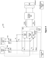
- FIG. 4 provides a more comprehensive illustration of the system architecture, in which both the main utility power source as well as the PV power source are employed.
- either power source can used for powering the TEC 426 and cooling pump 423. This arrangement enables enhanced cooling even when the solar panels do not receive sunlight, such as under cloudy conditions.
- FIG. 5 illustrates another embodiment of utilizing solar power.
- the solar power may be used to power the IT cooling components as well as the facility side or cluster side cooling enhancement design.
- the cooling system shown in Figure 5 represent both a facility level unit, a cluster level unit or rack level unit.
- the cooling system is used to process and deliver cooling liquid to the IT racks, and receives hot return fluid.
- temperature sensor 522 delivers temperature measurements to the controller 520, which controls the delivery of power from the PV system 510 to the TECs 526 by closing switches S 1 and S 3 .
- the controller 520 also closes switch S 2 to deliver PV power to the cooling enhancement system.
- FIG. 6 is a flow chart illustrating a process according to an embodiment. This embodiment corresponds to an arrangement wherein the PV power output is dedicated to powering the TEC system.
- the flow chart shows the fundamental method for controlling the switches using ambient temperature. The temperature can be obtained using sensors that are part of the control system or obtaining reading from existing sensor that form part of the existing data center infrastructure.
- step 615 the controller closes the switches to the TEC to provide power from the converter to the TEC. Thereafter the controller continues to monitor the temperature, so that so long as the temperature remains high, the connection to the TEC is maintained. Conversely, when in step 620 it is determined that the temperature T dropped below a preset threshold Th, which may be different from the onset threshold of step 605, the controller reverts to the initial state of step 600, wherein all the switches are opened.
- a preset threshold Th which may be different from the onset threshold of step 605
- Figure 7 is a flow chart illustrating control process according to an embodiment.
- the control operation corresponds to an embodiment wherein the PV system is connected to multiple types of IT loads, as exemplified in several embodiments disclosed herein.
- the process of Figure 7 There are two design goals implemented by the process of Figure 7 .
- the current operation design can be integrated into existing infrastructure and control architecture.
- the process can enable further optimization of the cooling operations.
- the PV power may also be used for battery based energy system, while using the temperature measurements to connect the PV system to the batteries.
- the temperature set point for connecting the PV system to the batteries may be lower than the set point for running/powering the TEC.
- an optimized solution may be configured for performance enhancement, including both cooling performance as well as computing performance.
- step 705 it is determined whether usable solar power is available, based on the temperature measurement. As indicated in Figure 7 , optionally, as a backup, voltage measurement may also be used to determine the availability of usable solar power. As shown in Figure 2 , the readings of the temperature sensor 222 and the voltage sensor 217, as well as the switches, are correlated. So long as no usable solar power is available, the process reverts to the initial state of step 700.
- step 710 When in step 705 it is determined that usable power is available, in step 710 the main switch is closed so as to connect the PV system to the converter. Then in step 715 it is determined whether the available power is higher than the heat load threshold. If not, the process proceeds to step 730, wherein the converter is connected to charge the batteries. Conversely, if the available power is higher than the heat load threshold, the process proceeds to step 720 to determine whether additional computing power is needed. If not, the process proceeds to step 735 wherein the solar power is applied to the TEC. Conversely, in step 725 the controller applies the PV power to both the TEC and the server while optimizing the power distribution among the TEC and server.
- a power supply system for a computing system having a cooling system comprising a solar power system and a controller, the controller connected to an ambient temperature sensor measuring the ambient temperature outside the facility housing the computing system, wherein when the temperature sensor provides a temperature reading that is above a present threshold the controller is programmed to connect the solar power system to a power converter and connect the power converter to the cooling system.
- the cooling system may include thermoelectric cooling TEC and cooling pumps.
- the solar power may be applied to the servers within the computing system and/or to batteries.
- the controller may alternate the supplied power between utility power and solar power according to the temperature reading of the temperature sensor.
- a voltage sensor may be positioned to read the voltage provided by the solar system as a backup to the temperature sensor.
Landscapes
- Engineering & Computer Science (AREA)
- Theoretical Computer Science (AREA)
- Physics & Mathematics (AREA)
- General Engineering & Computer Science (AREA)
- Microelectronics & Electronic Packaging (AREA)
- Power Engineering (AREA)
- General Physics & Mathematics (AREA)
- Human Computer Interaction (AREA)
- Thermal Sciences (AREA)
- Computer Hardware Design (AREA)
- Cooling Or The Like Of Electrical Apparatus (AREA)
- Power Sources (AREA)
Applications Claiming Priority (1)
| Application Number | Priority Date | Filing Date | Title |
|---|---|---|---|
| US17/147,656 US11848641B2 (en) | 2021-01-13 | 2021-01-13 | Temperature based self-regulated cooling enhancement |
Publications (2)
| Publication Number | Publication Date |
|---|---|
| EP3958424A2 true EP3958424A2 (de) | 2022-02-23 |
| EP3958424A3 EP3958424A3 (de) | 2022-12-21 |
Family
ID=79230557
Family Applications (1)
| Application Number | Title | Priority Date | Filing Date |
|---|---|---|---|
| EP21218487.3A Pending EP3958424A3 (de) | 2021-01-13 | 2021-12-31 | Verbesserung von temperaturbasierter selbstregulierender kühlung |
Country Status (4)
| Country | Link |
|---|---|
| US (1) | US11848641B2 (de) |
| EP (1) | EP3958424A3 (de) |
| JP (1) | JP7274001B2 (de) |
| CN (1) | CN114765383A (de) |
Families Citing this family (2)
| Publication number | Priority date | Publication date | Assignee | Title |
|---|---|---|---|---|
| US11930625B2 (en) * | 2021-03-26 | 2024-03-12 | Baidu Usa Llc | Thermal management system and method for power optimization for cooling an electronic rack |
| US20220338374A1 (en) * | 2021-04-20 | 2022-10-20 | Nvidia Corporation | Quick disconnect blind-mate manifold |
Family Cites Families (15)
| Publication number | Priority date | Publication date | Assignee | Title |
|---|---|---|---|---|
| JPH0854901A (ja) | 1994-08-09 | 1996-02-27 | Yoshio Ito | 負荷選別制御方法及び装置 |
| JPH1134647A (ja) * | 1997-07-15 | 1999-02-09 | Daido Hoxan Inc | 自動車用冷暖房システム |
| JP3990266B2 (ja) | 2002-04-08 | 2007-10-10 | Hoya株式会社 | 保持ホルダーおよび眼鏡枠形状測定装置 |
| JP2009271643A (ja) | 2008-05-01 | 2009-11-19 | Fujitsu Ltd | 電子機器用筐体及び電子装置 |
| US20140343745A1 (en) | 2009-11-25 | 2014-11-20 | Io Data Centers, Llc | Modular data center |
| JP2011200097A (ja) * | 2010-02-26 | 2011-10-06 | Sanyo Electric Co Ltd | 空調システム |
| CN102520744A (zh) * | 2011-12-12 | 2012-06-27 | 合肥聚能新能源科技有限公司 | 一种光伏恒温变流器的恒温控制系统 |
| US9891679B2 (en) * | 2011-12-22 | 2018-02-13 | Astec International Limited | Single phase redundant power supply systems for reducing phase current imbalances |
| US8925333B2 (en) | 2012-09-13 | 2015-01-06 | International Business Machines Corporation | Thermoelectric-enhanced air and liquid cooling of an electronic system |
| US9297559B2 (en) * | 2013-09-25 | 2016-03-29 | Intel Corporation | Adaptive thermoelectric cooling in a processor |
| US9857809B2 (en) * | 2013-12-30 | 2018-01-02 | Intel Corporation | Fuzzy logic control of thermoelectric cooling in a processor |
| JP6466716B2 (ja) | 2015-01-08 | 2019-02-06 | 株式会社Nttファシリティーズ | 空調装置 |
| US20170299237A1 (en) * | 2016-04-17 | 2017-10-19 | Andrew Xianyi Huang | Solar-powered system |
| US11455021B2 (en) * | 2016-08-18 | 2022-09-27 | Cato | Datacenter power management using AC and DC power sources |
| KR101991416B1 (ko) * | 2017-10-01 | 2019-06-20 | 김건민 | 서버용 쿨링랙 장치 |
-
2021
- 2021-01-13 US US17/147,656 patent/US11848641B2/en active Active
- 2021-11-10 CN CN202111324211.7A patent/CN114765383A/zh active Pending
- 2021-12-31 EP EP21218487.3A patent/EP3958424A3/de active Pending
-
2022
- 2022-01-05 JP JP2022000362A patent/JP7274001B2/ja active Active
Also Published As
| Publication number | Publication date |
|---|---|
| EP3958424A3 (de) | 2022-12-21 |
| US11848641B2 (en) | 2023-12-19 |
| CN114765383A (zh) | 2022-07-19 |
| US20220224286A1 (en) | 2022-07-14 |
| JP7274001B2 (ja) | 2023-05-15 |
| JP2022046739A (ja) | 2022-03-23 |
Similar Documents
| Publication | Publication Date | Title |
|---|---|---|
| EP3958424A2 (de) | Temperaturbasierte selbstregulierte kühlverbesserung | |
| US9035617B2 (en) | Control system for a flow cell battery | |
| US9099893B2 (en) | Power control device for a power grid, comprising a control unit for controlling an energy flow between the power generation unit, the energy storage unit, the consumer unit and/or the power grid | |
| US10476297B2 (en) | Device and method for wiring a battery management system | |
| US11670812B1 (en) | Thermal management device for energy storage system, method for controlling the thermal management device for energy storage system, and energy storage system | |
| CN104092236A (zh) | 混合型再生能源与储能系统供电系统及其控制方法 | |
| CN111682569A (zh) | 一种智能控制的储能系统 | |
| CN111433996A (zh) | 分级电力控制系统 | |
| KR20210083985A (ko) | 태양에너지를 이용한 마을단위 마이크로그리드 시스템 | |
| US20210249896A1 (en) | Power supply management system and method for use with one or multiple different utility proxies | |
| CN218771422U (zh) | 一种模块式绿电制氢储用控制系统 | |
| JP2012151977A (ja) | 負荷平準化システム | |
| KR102298838B1 (ko) | 태양광 에너지를 이용한 하이브리드 최적 운전방식의 저온 저장고 시스템 | |
| KR20200005070A (ko) | 무정전 전력 공급 관리 시스템 | |
| KR102222843B1 (ko) | 계층형 전력 제어 시스템 | |
| KR102222847B1 (ko) | 계층형 전력 제어 시스템 | |
| KR20200019915A (ko) | 무정전 전력 공급 관리 시스템 | |
| US20230074678A1 (en) | Power supply system | |
| KR20240032473A (ko) | 에너지 저장장치 | |
| US11614783B2 (en) | Method and system for providing power from a utility power source or a photovoltaic (PV) system to information technology | |
| CN220674155U (zh) | 服务器系统及服务器一体机柜 | |
| KR20240011295A (ko) | 에너지 저장장치 | |
| KR20240011294A (ko) | 에너지 저장장치 | |
| KR20240053785A (ko) | 에너지 저장장치 | |
| KR20240009566A (ko) | 에너지 저장장치 |
Legal Events
| Date | Code | Title | Description |
|---|---|---|---|
| PUAI | Public reference made under article 153(3) epc to a published international application that has entered the european phase |
Free format text: ORIGINAL CODE: 0009012 |
|
| STAA | Information on the status of an ep patent application or granted ep patent |
Free format text: STATUS: REQUEST FOR EXAMINATION WAS MADE |
|
| 17P | Request for examination filed |
Effective date: 20211231 |
|
| AK | Designated contracting states |
Kind code of ref document: A2 Designated state(s): AL AT BE BG CH CY CZ DE DK EE ES FI FR GB GR HR HU IE IS IT LI LT LU LV MC MK MT NL NO PL PT RO RS SE SI SK SM TR |
|
| PUAL | Search report despatched |
Free format text: ORIGINAL CODE: 0009013 |
|
| AK | Designated contracting states |
Kind code of ref document: A3 Designated state(s): AL AT BE BG CH CY CZ DE DK EE ES FI FR GB GR HR HU IE IS IT LI LT LU LV MC MK MT NL NO PL PT RO RS SE SI SK SM TR |
|
| RIC1 | Information provided on ipc code assigned before grant |
Ipc: G06F 1/20 20060101ALI20221111BHEP Ipc: H02J 3/46 20060101ALI20221111BHEP Ipc: G06F 1/26 20060101ALI20221111BHEP Ipc: H02J 3/14 20060101AFI20221111BHEP |
|
| STAA | Information on the status of an ep patent application or granted ep patent |
Free format text: STATUS: EXAMINATION IS IN PROGRESS |
|
| 17Q | First examination report despatched |
Effective date: 20230908 |