EP3957970A1 - Method of detecting a bearing fault - Google Patents
Method of detecting a bearing fault Download PDFInfo
- Publication number
- EP3957970A1 EP3957970A1 EP20191306.8A EP20191306A EP3957970A1 EP 3957970 A1 EP3957970 A1 EP 3957970A1 EP 20191306 A EP20191306 A EP 20191306A EP 3957970 A1 EP3957970 A1 EP 3957970A1
- Authority
- EP
- European Patent Office
- Prior art keywords
- bearing fault
- bearing
- shaft
- shaft displacement
- residual vector
- Prior art date
- Legal status (The legal status is an assumption and is not a legal conclusion. Google has not performed a legal analysis and makes no representation as to the accuracy of the status listed.)
- Pending
Links
Images

Classifications
-
- G—PHYSICS
- G01—MEASURING; TESTING
- G01M—TESTING STATIC OR DYNAMIC BALANCE OF MACHINES OR STRUCTURES; TESTING OF STRUCTURES OR APPARATUS, NOT OTHERWISE PROVIDED FOR
- G01M13/00—Testing of machine parts
- G01M13/04—Bearings
- G01M13/045—Acoustic or vibration analysis
-
- G—PHYSICS
- G01—MEASURING; TESTING
- G01M—TESTING STATIC OR DYNAMIC BALANCE OF MACHINES OR STRUCTURES; TESTING OF STRUCTURES OR APPARATUS, NOT OTHERWISE PROVIDED FOR
- G01M13/00—Testing of machine parts
- G01M13/04—Bearings
-
- G—PHYSICS
- G06—COMPUTING OR CALCULATING; COUNTING
- G06F—ELECTRIC DIGITAL DATA PROCESSING
- G06F30/00—Computer-aided design [CAD]
- G06F30/10—Geometric CAD
- G06F30/17—Mechanical parametric or variational design
Definitions
- the present disclosure generally relates to bearing fault detection.
- Electric motors are a key component that enables modern, efficient production. For a company to globally stay competitive its motors should be running 24/7.
- acceleration measurement-based vibration analysis is the dominant technique used for condition monitoring of rotating electrical machines.
- the sensitivity of capacitive displacement sensors is better in the low frequency area. That is why it may be assumed that faults appearing in the low frequency area of the vibration spectrum such as unbalance, misalignment, and eccentricity, can be detected and assessed more reliably and accurately by using displacement sensors instead of accelerometers.
- a decisive factor when considering replacing an accelerometer in condition monitoring is the ability of the displacement sensor to detect faults in the rolling element bearings, since more than half of the breakdowns of electrical motors are due to failures of the bearings.
- EP2918964 A1 discloses a sensor comprising a capacitive sensor for sensing the position or motion of a shaft comprising an electrically conducting part.
- the sensor utilises the sensor PCB that comprises a mounting hole through which the conducting part of the shaft can be mounted, at least one capacitor electrode formed to the printed circuit board, wherein an electrode surface of the electrode extends parallel to a centre axis of the mounting hole and faces the centre axis.
- a general object of the present disclosure is to provide a method that solves or at least mitigates the problems of the prior art.
- a method of detecting a bearing fault of a rolling element bearing mounted around a shaft using a shaft displacement sensor providing a shaft displacement signal to detect shaft displacement, the method comprising: a) subtracting a modelled shaft displacement reference signal from the shaft displacement signal to obtain a residual vector, b) estimating for at least one bearing fault type a respective bearing fault frequency, and estimating, for each bearing fault type, an amplitude of the residual vector in a frequency range containing a bearing fault frequency of the associated bearing fault type, and d) determining whether a bearing fault is present based on the at least one estimated amplitude.
- One embodiment comprises c) determining a bearing fault indicator for each bearing fault frequency by comparing the corresponding estimated amplitude to a noise floor of a signal defined by the residual vector, wherein step d) involves determining whether a bearing fault is present based on the magnitude of at least one bearing fault indicator.
- a very accurate bearing fault detection can thereby be obtained.
- a bearing fault can therefore be detected at an early stage before further progression. It furthermore reduces the risk of incorrect conclusions about bearing faults. This may be achieved because it can be determined more precisely whether the estimated amplitudes in the frequency ranges associated with the respective residual vector frequencies are random noise and thus not indicative of a bearing fault or that they are in fact generated because of a bearing fault.
- the frequency ranges may be selected so that they exclude frequencies with known disturbances.
- Step d) may involve determining that a bearing fault is present in case at least one of the magnitudes is greater than a threshold value.
- Each bearing fault indicator may provide an indication of an associated bearing fault type, in case its magnitude is greater than a threshold value.
- the method may involve determining that a bearing fault is present, without identifying its type, by determining that one of the bearing fault indicators has a magnitude greater than a threshold value. In the latter case, the method may not analyse which one or ones of the bearing fault indicators has a magnitude greater than a threshold value.
- the shaft displacement signal from the shaft displacement sensor is preferably measured during steady-state operating conditions of the shaft.
- step c) involves determining the noise floor based on the median of an amplitude spectrum of the signal defined by the residual vector.
- the amplitude spectrum may be scaled.
- the amplitude spectrum may be scaled so that its scale is comparable to the scale of the estimated amplitudes.
- the amplitude spectrum may be determined using a weight function, such as a Hanning window, multiplied with each term of a sum defining the amplitude spectrum.
- the amplitude spectrum may be normalised using a normalising factor.
- the normalising factor may utilise a Hanning window. Because of the scaling, the magnitude of the peaks in the amplitude spectrum will correspond in size to those of the shaft displacement signal. This facilitates comparison between the estimated amplitudes, which may be calculated by the maximum likelihood method, and the noise floor, which may be obtained using the Discrete Fourier Transform (DFT) method, to obtain proper bearing fault indicators.
- DFT Discrete Fourier Transform
- the comparison in step c) involves dividing the respective estimated amplitude with the noise floor.
- step d) involves using at least one bearing fault indicator in a sequential probability ratio method or a cumulative sum method to determine whether a bearing fault is present.
- More robust decision-making may thereby be provided, which is based on a learning process involving historical values of the bearing fault indicators and their deviations from the historical values.
- the modelled shaft displacement reference signal is modelled by a Fourier series comprising shaft rotation speed harmonics.
- the shaft rotation speed may for example be determined by measurement or estimation.
- step d) involves maximising the likelihood of a sinusoidal model of the residual vector in the frequency ranges containing the corresponding bearing fault frequency to estimate the residual vector frequencies and the amplitudes.
- the bearing fault types are at least two of the group of outer race fault, inner race fault, ball or roller fault, and gage fault.
- Each bearing fault type is associated with a respective reference fault frequency.
- the reference fault frequencies may for example be determined empirically.
- Each frequency range is based on and contains the corresponding reference fault frequency.
- a computer program comprising computer code which when executed by processing circuitry of a bearing fault detector causes the bearing fault detector to perform the method of the first aspect.
- a bearing fault detector for detecting a bearing fault of a rolling element bearing mounted around a shaft, using a shaft displacement sensor configured to provide a shaft displacement sensor to detect shaft displacement
- the bearing fault detector comprising: a storage medium comprising computer code, and processing circuitry, wherein when the processing circuitry executes the computer code, the bearing fault detector is configured to: subtract a modelled shaft displacement reference signal from the shaft displacement signal to obtain a residual vector, estimate for at least one bearing fault type a respective bearing fault frequency and estimating, for each bearing fault type, an amplitude of the residual vector in a frequency range containing a bearing fault frequency of the associated bearing fault type, and determine whether a bearing fault is present based on the at least one estimated amplitude.
- the processing circuitry is configured to determine the noise floor based on the median of an amplitude spectrum of the signal defined by the residual vector.
- the processing circuitry is configured to determine the bearing fault indicators by dividing the respective estimated amplitude with the noise floor.
- the modelled shaft displacement reference signal is modelled by a Fourier series comprising shaft rotation speed harmonics.
- the processing circuitry is configured to estimate the residual vector frequencies and the amplitudes by maximising the likelihood of a sinusoidal model of the residual vector in the frequency ranges containing the corresponding bearing fault frequency.
- a fourth aspect of the present disclosure provided a system comprising: an electrical machine comprising a rotatable shaft, a shaft displacement sensor configured to be arranged around the shaft, and a bearing fault detector according to the third aspect configured to receive a shaft displacement signal from the shaft displacement sensor.
- the electrical machine may be a motor or a generator.
- the shaft displacement sensor may be a capacitive sensor.
- the shaft may comprise an electrically conducting part and the shaft displacement sensor may be arranged around the electrically conducting part.
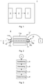
- Fig. 1 depicts a block diagram of an example of a bearing fault detector 1.
- the bearing fault detector 1 is configured to detect a bearing fault of a rolling element bearing mounted around a shaft.
- the shaft may for example be a rotor shaft of an electrical machine such as a motor or generator.
- the bearing fault detector 1 comprises an input unit 3 configured to receive a shaft displacement signal from a shaft displacement sensor.
- the bearing fault detector 1 comprises processing circuitry 5 and may comprise a storage medium 7.
- the storage medium 7 may comprise a computer program which when executed by the processing circuitry 7 causes the bearing fault detector 1 to perform the method as disclosed herein.
- the processing circuitry 5 may for example use any combination of one or more of a suitable central processing unit (CPU), multiprocessor, microcontroller, digital signal processor (DSP), application specific integrated circuit (ASIC), field programmable gate arrays (FPGA) etc., capable of executing any herein disclosed operations concerning bearing fault detection.
- CPU central processing unit
- DSP digital signal processor
- ASIC application specific integrated circuit
- FPGA field programmable gate arrays
- the storage medium 7 may for example be embodied as a memory, such as a random access memory (RAM), a read-only memory (ROM), an erasable programmable read-only memory (EPROM), or an electrically erasable programmable read-only memory (EEPROM) and more particularly as a non-volatile storage medium of a device in an external memory such as a USB (Universal Serial Bus) memory or a Flash memory, such as a compact Flash memory.
- RAM random access memory
- ROM read-only memory
- EPROM erasable programmable read-only memory
- EEPROM electrically erasable programmable read-only memory
- Fig. 2 shows an example of a system 9.
- the system 9 comprises an electrical machine 11.
- the electrical machine 11 is a rotating electrical machine.
- the electrical machine 11 may be a motor or a generator.
- the electrical machine 11 is shown in a longitudinal section in Fig. 2 .
- the electrical machine 11 comprises a stator 11a and a rotor 11b.
- the stator 11a and the rotor 11b are configured to electromagnetically interact with each other.
- the rotor 11b comprises a shaft 11c.
- the shaft 11c is rotatable about a longitudinal shaft axis A.
- the shaft axis A coincides with the Z-axis of the electrical machine 11.
- the electrical machine 11 also has an X-axis and a Y-axis.
- the X-axis and the Y-axis are radial axes with respect to the shaft 11c and the longitudinal shaft axis A.
- the electrical machine 11 comprises rolling element bearings 13 and 15 attached to the shaft 11c.
- the rolling element bearings 13 and 15 enable rotation of the shaft 11c.
- the rolling element bearing 15 has an inner bearing race 15a attached to the shaft 11c.
- the bearing 15 has an outer bearing race 15b attached to a support structure (not shown) which supports the rotor 11b.
- the rolling element bearing 13 is similar or identical to the rolling element bearing 15.
- the system 9 comprises at least one shaft displacement sensor 17.
- the shaft displacement sensor 17 is arranged around the shaft 11c.
- the shaft displacement sensor 17 may for example be installed adjacent to the rolling element bearing 15.
- the shaft displacement sensor 17 may have a through-opening and the shaft 11c may extend through the through-opening.
- the shaft displacement sensor 17 may be a capacitive sensor.
- the shaft displacement sensor 17 may for example be of the type disclosed in EP2918964 A1 .
- the shaft displacement sensor 17 may be configured to detect shaft displacement along the X-axis and the Y-axis.
- the shaft displacement signal may comprise both X-axis displacement measurements and Y-axis displacement measurements of the shaft 11c.
- the system 9 comprises the bearing fault detector 1.
- the bearing fault detector 1 is configured to receive the shaft displacement signal, which is a measurement signal made by the shaft displacement sensor 17.
- the bearing fault detector 1 may be configured to receive the shaft displacement signal by wireless communication, by wired communication or by a combination of both.
- the shaft displacement signal may be modelled using a Fourier series.
- the sine or cosine functions in the Fourier series include rotation speed harmonics of the fundamental frequency, which is the rotation speed of the shaft 11c.
- n is the discrete time index
- M is the number of harmonics in the model
- Frequencies f m and f s are the analog signal frequency and sampling frequency, respectively
- ⁇ [ n ] is a noise term.
- the rotation speed ⁇ 1 of the fundamental may for example be determined by measurement or estimation.
- a step a) the modelled shaft displacement reference signal s y [n] is subtracted from the shaft displacement signal y[n] obtained from the shaft displacement sensor 17.
- y[n] is the discretised shaft displacement signal.
- Step a) also involves obtaining the residual vector x r [n] for the shaft displacement signal x[n] in the x-direction by subtraction with the modelled shaft displacement reference signal s x [n] in the x-direction.
- FIG. 4a An example of a shaft displacement signal y[n] is shown in Fig. 4a .
- the rolling element bearing 15 has an outer bearing race fault indicated by the periodic pulses in the shaft displacement signal y[n].
- An example of a modelled shaft displacement reference signal s y [n] is also shown in Fig. 4a .
- Fig. 4b shows the residual vector y r obtained when the modelled shaft displacement reference signal s y [n] has been subtracted from the shaft displacement signal y[n].
- the presence of a fault may not be known at this time because there may exist small pulses in the shaft displacement signal for many reasons although the bearing is healthy.
- the characteristic that separates these pulses from pulses due to a bearing fault is the repetition frequency.
- the question is whether these periodic disturbances significantly differ from the amplitude of random noise. If the shaft 11c is rotating at constant speed, the displacement due to a fault will occur periodically at one of the bearing fault frequencies.
- a value of the residual vector at each sample n is obtained by the subtraction of the modelled shaft displacement reference signal s y [n] from the shaft displacement signal y[n].
- a sinusoidal model that mathematically describes the residual vector, for both x-direction and y-direction displacement, can be determined by a sum of sinusoidal functions.
- B k i are the corresponding amplitudes, i.e. the amplitudes at the fundamental/first harmonic defined by the corresponding bearing fault frequency f ff i and at corresponding upper harmonics.
- ⁇ k i are the corresponding phases.
- a step b) the bearing fault frequencies f ff i and corresponding amplitudes B k i of the frequency spectrum of the residual vector y r [n] are estimated.
- the frequency spectrum is thus that of the sinusoidal model of the residual vector y r [n].
- Each bearing fault frequency f ff i may be estimated by maximising the likelihood of the sinusoidal model of the residual vector y r [n] in a respective frequency range f min i f max i each containing a known bearing fault frequency.
- the bearing fault frequency and corresponding amplitudes can thus be estimated for a plurality of different bearing fault types.
- bearing fault indicators FI i are determined for each bearing fault frequency.
- the bearing fault indicators FI i are determined by comparing the corresponding first estimated amplitude, i.e. at the corresponding fundamental frequency, to a noise floor of a signal defined by the residual vector, i.e. the sinusoidal model of the residual vector.
- the estimated amplitudes may be divided with the median of the amplitude spectrum of the signal defined by the residual vector y r [n].
- the estimated amplitudes may be divided with the median of a scaled and normalised amplitude spectrum P BT i f .
- the amplitude spectrum is the absolute value of the discrete Fourier transform of the sinusoidal model of the residual vector, or the absolute value of a scaled discrete Fourier transform that is normalised.
- the bearing fault indicators FI i provide a measure of the significance of the size of the estimated amplitudes compared to random noise.
- a bearing fault it is determined whether a bearing fault is present based on the estimated amplitude.
- the presence of a fault may for example be determined directly from the size or magnitude of the estimated amplitude.
- the first estimated amplitude i.e. the largest estimated amplitude may be used for determining the presence of a bearing fault.
- the estimated amplitude has a magnitude greater than a predetermined value, it can be concluded that a bearing fault is present.
- the presence of a bearing fault may be determined based on the magnitudes of the bearing fault indicators FI i .
- Step d) may involve using binary decision theory for decision-making to choose between two hypotheses, namely Ho: the condition of the bearing is normal and Hi: there is a bearing fault. For example, if one of the bearing fault indicators FI i has a magnitude greater than a threshold value it may be concluded that a bearing fault is present.
- step d) may involve using the bearing fault indicators FI i in a sequential probability ratio method or a cumulative sum method to determine whether a bearing fault is present.
Landscapes
- Physics & Mathematics (AREA)
- General Physics & Mathematics (AREA)
- Geometry (AREA)
- Engineering & Computer Science (AREA)
- Theoretical Computer Science (AREA)
- Pure & Applied Mathematics (AREA)
- Mathematical Optimization (AREA)
- Mathematical Analysis (AREA)
- Computer Hardware Design (AREA)
- Evolutionary Computation (AREA)
- General Engineering & Computer Science (AREA)
- Computational Mathematics (AREA)
- Acoustics & Sound (AREA)
- Testing Of Devices, Machine Parts, Or Other Structures Thereof (AREA)
- Measurement Of Mechanical Vibrations Or Ultrasonic Waves (AREA)
Abstract
Description
- The present disclosure generally relates to bearing fault detection.
- Electric motors are a key component that enables modern, efficient production. For a company to globally stay competitive its motors should be running 24/7.
- Today, acceleration measurement-based vibration analysis is the dominant technique used for condition monitoring of rotating electrical machines. In contrast to accelerometers, the sensitivity of capacitive displacement sensors is better in the low frequency area. That is why it may be assumed that faults appearing in the low frequency area of the vibration spectrum such as unbalance, misalignment, and eccentricity, can be detected and assessed more reliably and accurately by using displacement sensors instead of accelerometers. However, a decisive factor when considering replacing an accelerometer in condition monitoring is the ability of the displacement sensor to detect faults in the rolling element bearings, since more than half of the breakdowns of electrical motors are due to failures of the bearings.
-
EP2918964 A1 discloses a sensor comprising a capacitive sensor for sensing the position or motion of a shaft comprising an electrically conducting part. The sensor utilises the sensor PCB that comprises a mounting hole through which the conducting part of the shaft can be mounted, at least one capacitor electrode formed to the printed circuit board, wherein an electrode surface of the electrode extends parallel to a centre axis of the mounting hole and faces the centre axis. - In the early stage of the usual bearing fault progression a macroscopic and self-propagating crack appears on the defective surface. Even in the early fault stages the depth of the local fault is several micrometres, thus detectable by an accurate shaft displacement sensor. This fault produces a series of weak impacts and displacements at a rate dependent on the bearing geometry.
- If the shaft is rotating at constant speed, displacements due to a fault will occur periodically with a certain frequency, which can be calculated by the location of the fault, the bearing geometry and the shaft speed. These frequencies are known as the bearing fault frequencies and can be determined for a fault on:
- the outer race,
- the inner race,
- the ball or roller, and
- the gage.
- A general object of the present disclosure is to provide a method that solves or at least mitigates the problems of the prior art.
- There is hence according to a first aspect of the present disclosure provided a method of detecting a bearing fault of a rolling element bearing mounted around a shaft, using a shaft displacement sensor providing a shaft displacement signal to detect shaft displacement, the method comprising: a) subtracting a modelled shaft displacement reference signal from the shaft displacement signal to obtain a residual vector, b) estimating for at least one bearing fault type a respective bearing fault frequency, and estimating, for each bearing fault type, an amplitude of the residual vector in a frequency range containing a bearing fault frequency of the associated bearing fault type, and d) determining whether a bearing fault is present based on the at least one estimated amplitude.
- Fault detection of the rolling element bearing may thereby be obtained.
- One embodiment comprises c) determining a bearing fault indicator for each bearing fault frequency by comparing the corresponding estimated amplitude to a noise floor of a signal defined by the residual vector, wherein step d) involves determining whether a bearing fault is present based on the magnitude of at least one bearing fault indicator.
- A very accurate bearing fault detection can thereby be obtained. A bearing fault can therefore be detected at an early stage before further progression. It furthermore reduces the risk of incorrect conclusions about bearing faults. This may be achieved because it can be determined more precisely whether the estimated amplitudes in the frequency ranges associated with the respective residual vector frequencies are random noise and thus not indicative of a bearing fault or that they are in fact generated because of a bearing fault.
- The frequency ranges may be selected so that they exclude frequencies with known disturbances.
- Step d) may involve determining that a bearing fault is present in case at least one of the magnitudes is greater than a threshold value.
- Each bearing fault indicator may provide an indication of an associated bearing fault type, in case its magnitude is greater than a threshold value. Alternatively, the method may involve determining that a bearing fault is present, without identifying its type, by determining that one of the bearing fault indicators has a magnitude greater than a threshold value. In the latter case, the method may not analyse which one or ones of the bearing fault indicators has a magnitude greater than a threshold value.
- The shaft displacement signal from the shaft displacement sensor is preferably measured during steady-state operating conditions of the shaft.
- According to one embodiment step c) involves determining the noise floor based on the median of an amplitude spectrum of the signal defined by the residual vector.
- The amplitude spectrum may be scaled. The amplitude spectrum may be scaled so that its scale is comparable to the scale of the estimated amplitudes.
- The amplitude spectrum may be determined using a weight function, such as a Hanning window, multiplied with each term of a sum defining the amplitude spectrum. The amplitude spectrum may be normalised using a normalising factor. The normalising factor may utilise a Hanning window. Because of the scaling, the magnitude of the peaks in the amplitude spectrum will correspond in size to those of the shaft displacement signal. This facilitates comparison between the estimated amplitudes, which may be calculated by the maximum likelihood method, and the noise floor, which may be obtained using the Discrete Fourier Transform (DFT) method, to obtain proper bearing fault indicators.
- According to one embodiment the comparison in step c) involves dividing the respective estimated amplitude with the noise floor.
- According to one embodiment step d) involves using at least one bearing fault indicator in a sequential probability ratio method or a cumulative sum method to determine whether a bearing fault is present.
- More robust decision-making may thereby be provided, which is based on a learning process involving historical values of the bearing fault indicators and their deviations from the historical values.
- According to one embodiment the modelled shaft displacement reference signal is modelled by a Fourier series comprising shaft rotation speed harmonics.
- The shaft rotation speed may for example be determined by measurement or estimation.
- According to one embodiment step d) involves maximising the likelihood of a sinusoidal model of the residual vector in the frequency ranges containing the corresponding bearing fault frequency to estimate the residual vector frequencies and the amplitudes.
- According to one embodiment the bearing fault types are at least two of the group of outer race fault, inner race fault, ball or roller fault, and gage fault.
- Each bearing fault type is associated with a respective reference fault frequency. The reference fault frequencies may for example be determined empirically. Each frequency range is based on and contains the corresponding reference fault frequency.
- There is according to a second aspect of the present disclosure provided a computer program comprising computer code which when executed by processing circuitry of a bearing fault detector causes the bearing fault detector to perform the method of the first aspect.
- There is according to a third aspect of the present disclosure provided a bearing fault detector for detecting a bearing fault of a rolling element bearing mounted around a shaft, using a shaft displacement sensor configured to provide a shaft displacement sensor to detect shaft displacement, the bearing fault detector comprising: a storage medium comprising computer code, and processing circuitry, wherein when the processing circuitry executes the computer code, the bearing fault detector is configured to: subtract a modelled shaft displacement reference signal from the shaft displacement signal to obtain a residual vector, estimate for at least one bearing fault type a respective bearing fault frequency and estimating, for each bearing fault type, an amplitude of the residual vector in a frequency range containing a bearing fault frequency of the associated bearing fault type, and determine whether a bearing fault is present based on the at least one estimated amplitude.
- According to one embodiment the processing circuitry is configured to determine the noise floor based on the median of an amplitude spectrum of the signal defined by the residual vector.
- According to one embodiment the processing circuitry is configured to determine the bearing fault indicators by dividing the respective estimated amplitude with the noise floor.
- According to one embodiment the processing circuitry is configured to determine whether a bearing fault is present using at least one bearing fault indicator in a sequential probability ratio method or a cumulative sum method
- According to one embodiment the modelled shaft displacement reference signal is modelled by a Fourier series comprising shaft rotation speed harmonics.
- According to one embodiment the processing circuitry is configured to estimate the residual vector frequencies and the amplitudes by maximising the likelihood of a sinusoidal model of the residual vector in the frequency ranges containing the corresponding bearing fault frequency.
- There is according to a fourth aspect of the present disclosure provided a system comprising: an electrical machine comprising a rotatable shaft, a shaft displacement sensor configured to be arranged around the shaft, and a bearing fault detector according to the third aspect configured to receive a shaft displacement signal from the shaft displacement sensor.
- The electrical machine may be a motor or a generator.
- The shaft displacement sensor may be a capacitive sensor.
- The shaft may comprise an electrically conducting part and the shaft displacement sensor may be arranged around the electrically conducting part.
- Generally, all terms used in the claims are to be interpreted according to their ordinary meaning in the technical field, unless explicitly defined otherwise herein. All references to "a/an/the element, apparatus, component, means, etc. are to be interpreted openly as referring to at least one instance of the element, apparatus, component, means, etc., unless explicitly stated otherwise.
- The specific embodiments of the inventive concept will now be described, by way of example, with reference to the accompanying drawings, in which:
-
Fig. 1 schematically shows a block diagram of a bearing fault detector; -
Fig. 2 schematically shows a block diagram of a system comprising the bearing fault detector inFig. 1 and an electrical machine; -
Fig. 3 is a flowchart of a method of detecting a bearing fault by means of a bearing fault detector; -
Fig. 4a is a graph showing a modelled shaft displacement reference signal and a shaft displacement signal in the presence of an outer race fault; and -
Fig. 4b is a graph showing the signal defined by the residual vector obtained from the signals shown inFig. 4a . - The inventive concept will now be described more fully hereinafter with reference to the accompanying drawings, in which exemplifying embodiments are shown. The inventive concept may, however, be embodied in many different forms and should not be construed as limited to the embodiments set forth herein; rather, these embodiments are provided by way of example so that this disclosure will be thorough and complete, and will fully convey the scope of the inventive concept to those skilled in the art. Like numbers refer to like elements throughout the description.
-
Fig. 1 depicts a block diagram of an example of abearing fault detector 1. Thebearing fault detector 1 is configured to detect a bearing fault of a rolling element bearing mounted around a shaft. The shaft may for example be a rotor shaft of an electrical machine such as a motor or generator. - The
bearing fault detector 1 comprises aninput unit 3 configured to receive a shaft displacement signal from a shaft displacement sensor. Thebearing fault detector 1 comprisesprocessing circuitry 5 and may comprise a storage medium 7. - The storage medium 7 may comprise a computer program which when executed by the processing circuitry 7 causes the
bearing fault detector 1 to perform the method as disclosed herein. - The
processing circuitry 5 may for example use any combination of one or more of a suitable central processing unit (CPU), multiprocessor, microcontroller, digital signal processor (DSP), application specific integrated circuit (ASIC), field programmable gate arrays (FPGA) etc., capable of executing any herein disclosed operations concerning bearing fault detection. - The storage medium 7 may for example be embodied as a memory, such as a random access memory (RAM), a read-only memory (ROM), an erasable programmable read-only memory (EPROM), or an electrically erasable programmable read-only memory (EEPROM) and more particularly as a non-volatile storage medium of a device in an external memory such as a USB (Universal Serial Bus) memory or a Flash memory, such as a compact Flash memory.
-
Fig. 2 shows an example of a system 9. The system 9 comprises anelectrical machine 11. Theelectrical machine 11 is a rotating electrical machine. Theelectrical machine 11 may be a motor or a generator. Theelectrical machine 11 is shown in a longitudinal section inFig. 2 . - The
electrical machine 11 comprises astator 11a and arotor 11b. Thestator 11a and therotor 11b are configured to electromagnetically interact with each other. Therotor 11b comprises ashaft 11c. Theshaft 11c is rotatable about a longitudinal shaft axis A. The shaft axis A coincides with the Z-axis of theelectrical machine 11. Theelectrical machine 11 also has an X-axis and a Y-axis. The X-axis and the Y-axis are radial axes with respect to theshaft 11c and the longitudinal shaft axis A. - The
electrical machine 11 comprises rollingelement bearings shaft 11c. The rollingelement bearings shaft 11c. - The rolling element bearing 15 has an
inner bearing race 15a attached to theshaft 11c. Thebearing 15 has anouter bearing race 15b attached to a support structure (not shown) which supports therotor 11b. The rolling element bearing 13 is similar or identical to the rolling element bearing 15. - The system 9 comprises at least one
shaft displacement sensor 17. Theshaft displacement sensor 17 is arranged around theshaft 11c. Theshaft displacement sensor 17 may for example be installed adjacent to the rolling element bearing 15. Theshaft displacement sensor 17 may have a through-opening and theshaft 11c may extend through the through-opening. Theshaft displacement sensor 17 may be a capacitive sensor. Theshaft displacement sensor 17 may for example be of the type disclosed inEP2918964 A1 . - The
shaft displacement sensor 17 may be configured to detect shaft displacement along the X-axis and the Y-axis. The shaft displacement signal may comprise both X-axis displacement measurements and Y-axis displacement measurements of theshaft 11c. - The system 9 comprises the
bearing fault detector 1. Thebearing fault detector 1 is configured to receive the shaft displacement signal, which is a measurement signal made by theshaft displacement sensor 17. Thebearing fault detector 1 may be configured to receive the shaft displacement signal by wireless communication, by wired communication or by a combination of both. - A method of detecting a bearing fault of the rolling element bearing 15 by means of the
bearing fault detector 1 will now be described with reference toFig. 3 . - In steady-state or stable operation of the
electrical machine 11 the shaft displacement signal may be modelled using a Fourier series. The sine or cosine functions in the Fourier series include rotation speed harmonics of the fundamental frequency, which is the rotation speed of theshaft 11c. The modelled shaft displacement reference signal in the Y-direction may be expressed as follows:
- The same expression applies also for the X-direction modelled shaft displacement reference signal. n is the discrete time index, M is the number of harmonics in the model, ωm = 2πνm is the m:th harmonic, νm = fm / fs is the digital frequency. Frequencies fm and fs are the analog signal frequency and sampling frequency, respectively, and ε[n] is a noise term.
- The rotation speed ω 1 of the fundamental may for example be determined by measurement or estimation.
- In a step a) the modelled shaft displacement reference signal sy[n] is subtracted from the shaft displacement signal y[n] obtained from the
shaft displacement sensor 17. A residual vector yr[n] is thus obtained, i.e. yr[n]= y[n]-sy[n]. y[n] is the discretised shaft displacement signal. - Step a) also involves obtaining the residual vector xr[n] for the shaft displacement signal x[n] in the x-direction by subtraction with the modelled shaft displacement reference signal sx[n] in the x-direction.
- In the following reference will generally only be made to the y-direction components, but the same also applies to the x-direction components.
- An example of a shaft displacement signal y[n] is shown in
Fig. 4a . In the example, the rolling element bearing 15 has an outer bearing race fault indicated by the periodic pulses in the shaft displacement signal y[n]. An example of a modelled shaft displacement reference signal sy[n] is also shown inFig. 4a . -
Fig. 4b shows the residual vector yr obtained when the modelled shaft displacement reference signal sy[n] has been subtracted from the shaft displacement signal y[n]. The presence of a fault may not be known at this time because there may exist small pulses in the shaft displacement signal for many reasons although the bearing is healthy. The characteristic that separates these pulses from pulses due to a bearing fault is the repetition frequency. Thus, the question is whether these periodic disturbances significantly differ from the amplitude of random noise. If theshaft 11c is rotating at constant speed, the displacement due to a fault will occur periodically at one of the bearing fault frequencies. - A value of the residual vector at each sample n is obtained by the subtraction of the modelled shaft displacement reference signal sy[n] from the shaft displacement signal y[n]. A sinusoidal model that mathematically describes the residual vector, for both x-direction and y-direction displacement, can be determined by a sum of sinusoidal functions. The sinusoidal model may be defined by a Fourier series as follows:


- In a step b) the bearing fault frequencies


- In an optional step step c) bearing fault indicators FIi are determined for each bearing fault frequency. The bearing fault indicators FIi are determined by comparing the corresponding first estimated amplitude, i.e. at the corresponding fundamental frequency, to a noise floor of a signal defined by the residual vector, i.e. the sinusoidal model of the residual vector. The estimated amplitudes may be divided with the median of the amplitude spectrum of the signal defined by the residual vector yr[n]. The estimated amplitudes may be divided with the median of a scaled and normalised amplitude spectrum


- Each bearing fault indicator FIi is the ratio between the first estimated amplitude


- The bearing fault indicators FIi provide a measure of the significance of the size of the estimated amplitudes compared to random noise.
- In a step d) it is determined whether a bearing fault is present based on the estimated amplitude. In step d) the presence of a fault may for example be determined directly from the size or magnitude of the estimated amplitude. For example, the first estimated amplitude, i.e. the largest estimated amplitude may be used for determining the presence of a bearing fault. For example, in case the estimated amplitude has a magnitude greater than a predetermined value, it can be concluded that a bearing fault is present.
- Alternatively, the presence of a bearing fault may be determined based on the magnitudes of the bearing fault indicators FIi.
- Step d) may involve using binary decision theory for decision-making to choose between two hypotheses, namely Ho: the condition of the bearing is normal and Hi: there is a bearing fault. For example, if one of the bearing fault indicators FIi has a magnitude greater than a threshold value it may be concluded that a bearing fault is present.
- According to one variation, step d) may involve using the bearing fault indicators FIi in a sequential probability ratio method or a cumulative sum method to determine whether a bearing fault is present.
- The inventive concept has mainly been described above with reference to a few examples. However, as is readily appreciated by a person skilled in the art, other embodiments than the ones disclosed above are equally possible within the scope of the inventive concept, as defined by the appended claims.
Claims (17)
- A method of detecting a bearing fault of a rolling element bearing (15) mounted around a shaft (11c), using a shaft displacement sensor (17) providing a shaft displacement signal (y[n]) to detect shaft displacement, the method comprising:a) subtracting a modelled shaft displacement reference signal (sy[n]) from the shaft displacement signal (y[n]) to obtain a residual vector (yr[n]),b) estimating for at least one bearing fault type a respective bearing fault frequency, and estimating, for each bearing fault type, an amplitude of the residual vector (yr[n]) in a frequency range containing a bearing fault frequency of the associated bearing fault type, andd) determining whether a bearing fault is present based on the at least one estimated amplitude.
- The method as claimed in claim 1, comprising c) determining a bearing fault indicator for each bearing fault frequency by comparing the corresponding estimated amplitude to a noise floor of a signal defined by the residual vector (yr[n]), wherein step d) involves determining whether a bearing fault is present based on the magnitude of at least one bearing fault indicator.
- The method as claimed in claim 2, wherein step c) involves determining the noise floor based on the median of an amplitude spectrum of the signal defined by the residual vector (yr[n]).
- The method as claimed in claim 2 or 3, wherein the comparison in step c) involves dividing the respective estimated amplitude with the noise floor.
- The method as claimed in any of claims 2-4, wherein step d) involves using at least one bearing fault indicator in a sequential probability ratio method or a cumulative sum method to determine whether a bearing fault is present.
- The method as claimed in any of the preceding claims, wherein the modelled shaft displacement reference signal (sy[n]) is modelled by a Fourier series comprising shaft rotation speed harmonics.
- The method as claimed in any of the preceding claims, wherein step d) involves maximising the likelihood of a sinusoidal model of the residual vector (yr[n]) in the frequency ranges containing the corresponding bearing fault frequency to estimate the residual vector frequencies and the amplitudes.
- The method as claimed in any of the preceding claims, wherein the bearing fault types are at least two of the group of outer race fault, inner race fault, ball or roller fault, and gage fault.
- A computer program comprising computer code which when executed by processing circuitry (5) of a bearing fault detector (1) causes the bearing fault detector (1) to perform the method as claimed in any of claims 1-8.
- A bearing fault detector (1) for detecting a bearing fault of a rolling element bearing (15) mounted around a shaft (11c), using a shaft displacement sensor (17) configured to provide a shaft displacement sensor (y[n]) to detect shaft displacement, the bearing fault detector (1) comprising:a storage medium (7) comprising computer code, andprocessing circuitry (5),wherein when the processing circuitry (5) executes the computer code, the bearing fault detector (1) is configured to:subtract a modelled shaft displacement reference signal (sy[n]) from the shaft displacement signal (y[n])to obtain a residual vector (yr[n]),estimate for at least one bearing fault type a respective bearing fault frequency and estimating, for each bearing fault type, an amplitude of the residual vector (yr[n]) in a frequency range containing a bearing fault frequency of the associated bearing fault type, anddetermine whether a bearing fault is present based on the at least one estimated amplitude.
- The bearing fault detector (1) as claimed in claim 10, wherein the processing circuitry (5) is configured to determine a bearing fault indicator for each bearing fault frequency by comparing the corresponding estimated amplitude to a noise floor of a signal defined by the residual vector, and to determine whether a bearing fault is present based on the magnitude of at least one bearing fault indicator.
- The bearing fault detector (1) as claimed in claim 11, wherein the processing circuitry (5) is configured to determine the noise floor based on the median of an amplitude spectrum of the signal defined by the residual vector (yr[n]).
- The bearing fault detector (1) as claimed in claim 11 or 12, wherein the processing circuitry (5) is configured to determine the bearing fault indicators by dividing the respective estimated amplitude with the noise floor.
- The bearing fault detector (1) as claimed in any of claims 11-13, wherein the processing circuitry (5) is configured to determine whether a bearing fault is present using at least one bearing fault indicator in a sequential probability ratio method or a cumulative sum method.
- The bearing fault detector (1) as claimed in any of claims 10-14, wherein the modelled shaft displacement reference signal (sy[n]) is modelled by a Fourier series comprising shaft rotation speed harmonics.
- The bearing fault detector (1) as claimed in any of claims 10-15, wherein the processing circuitry (5) is configured to estimate the residual vector frequencies and the amplitudes by maximising the likelihood of a sinusoidal model of the residual vector (yr[n]) in the frequency ranges containing the corresponding bearing fault frequency.
- A system (9) comprising:an electrical machine (11) comprising a rotatable shaft (11c),a shaft displacement sensor (17) configured to be arranged around the shaft (11c), anda bearing fault detector (1) as claimed in any of claims 10-16 configured to receive a shaft displacement signal (y[n]) from the shaft displacement sensor (17).
Priority Applications (3)
| Application Number | Priority Date | Filing Date | Title |
|---|---|---|---|
| EP20191306.8A EP3957970A1 (en) | 2020-08-17 | 2020-08-17 | Method of detecting a bearing fault |
| US17/397,123 US12535383B2 (en) | 2020-08-17 | 2021-08-09 | Method of detecting a bearing fault |
| CN202110937231.5A CN114152437A (en) | 2020-08-17 | 2021-08-16 | Method for detecting bearing failure |
Applications Claiming Priority (1)
| Application Number | Priority Date | Filing Date | Title |
|---|---|---|---|
| EP20191306.8A EP3957970A1 (en) | 2020-08-17 | 2020-08-17 | Method of detecting a bearing fault |
Publications (1)
| Publication Number | Publication Date |
|---|---|
| EP3957970A1 true EP3957970A1 (en) | 2022-02-23 |
Family
ID=72139487
Family Applications (1)
| Application Number | Title | Priority Date | Filing Date |
|---|---|---|---|
| EP20191306.8A Pending EP3957970A1 (en) | 2020-08-17 | 2020-08-17 | Method of detecting a bearing fault |
Country Status (3)
| Country | Link |
|---|---|
| US (1) | US12535383B2 (en) |
| EP (1) | EP3957970A1 (en) |
| CN (1) | CN114152437A (en) |
Families Citing this family (5)
| Publication number | Priority date | Publication date | Assignee | Title |
|---|---|---|---|---|
| EP3588049A1 (en) * | 2018-06-27 | 2020-01-01 | ABB Schweiz AG | Decision of faulty bearing |
| KR102572378B1 (en) * | 2021-05-20 | 2023-08-31 | 주식회사 원프레딕트 | Diagnosis method for bearing defect using 3 phase motor current signal and apparatus for performing the same |
| DE102021211493A1 (en) * | 2021-10-12 | 2023-04-13 | Aktiebolaget Skf | Device and method for estimating a load in a bearing |
| CN116358469B (en) * | 2023-03-10 | 2026-01-23 | 潍柴动力股份有限公司 | Engine crankshaft axial displacement testing method and device and electronic equipment |
| CN116465629B (en) * | 2023-03-24 | 2026-04-07 | 华能核能技术研究院有限公司 | Fault diagnosis methods and devices for electromagnetic bearings |
Citations (1)
| Publication number | Priority date | Publication date | Assignee | Title |
|---|---|---|---|---|
| US20160327452A1 (en) * | 2015-05-04 | 2016-11-10 | Deere & Company | Fault detection for bearings |
Family Cites Families (19)
| Publication number | Priority date | Publication date | Assignee | Title |
|---|---|---|---|---|
| JP2818172B2 (en) | 1988-11-30 | 1998-10-30 | 株式会社東芝 | Bearing abnormality diagnosis device |
| US5511422A (en) * | 1993-04-09 | 1996-04-30 | Monitoring Technology Corporation | Method and apparatus for analyzing and detecting faults in bearings and other rotating components that slip |
| US6321602B1 (en) * | 1999-09-28 | 2001-11-27 | Rockwell Science Center, Llc | Condition based monitoring by vibrational analysis |
| JP2005345277A (en) | 2004-06-03 | 2005-12-15 | Nsk Ltd | Monitoring device and monitoring method |
| DE102004027800B4 (en) * | 2004-06-08 | 2006-04-06 | Fag Kugelfischer Ag & Co. Ohg | Method and computer program for determining operating parameters in a rolling bearing and evaluable rolling bearing hereby |
| KR100758152B1 (en) * | 2006-03-23 | 2007-09-12 | 성균관대학교산학협력단 | Fault Diagnosis Using Behavior Response by Vibration Signal Quantization |
| US7421349B1 (en) * | 2006-05-15 | 2008-09-02 | United States Of America As Represented By The Secretary Of The Navy | Bearing fault signature detection |
| US7930111B2 (en) * | 2008-09-22 | 2011-04-19 | General Electric Company | Synthesized synchronous sampling and acceleration enveloping for differential bearing damage signature |
| JP5509720B2 (en) | 2009-08-07 | 2014-06-04 | 株式会社ジェイテクト | Rolling bearing device |
| MX351680B (en) * | 2012-05-31 | 2017-10-25 | Univ Connecticut | Methods apparatuses for defect diagnosis in a mechanical system. |
| EP2918964B1 (en) | 2014-03-14 | 2020-05-13 | ABB Schweiz AG | Method, sensor, and printed circuit board for sensing position or motion of a shaft |
| US10168248B1 (en) * | 2015-03-27 | 2019-01-01 | Tensor Systems Pty Ltd | Vibration measurement and analysis |
| EP3309530A1 (en) | 2016-10-11 | 2018-04-18 | ABB Schweiz AG | Detection of bearing fault |
| JP6751542B2 (en) | 2017-08-30 | 2020-09-09 | 公益財団法人鉄道総合技術研究所 | Bearing inspection equipment and bearing inspection program |
| CN109061474A (en) * | 2018-10-15 | 2018-12-21 | 株洲中车时代电气股份有限公司 | A kind of motor bearings trouble-shooter |
| CN109238698A (en) | 2018-10-15 | 2019-01-18 | 株洲中车时代电气股份有限公司 | A kind of motor bearings method for diagnosing faults based on current signal |
| KR102103331B1 (en) * | 2018-11-26 | 2020-04-23 | 주식회사 원프레딕트 | Apparatus and method for predicting breakdown of the bearing |
| US11099101B2 (en) * | 2019-05-03 | 2021-08-24 | Mitsubishi Electric Research Laboratories, Inc. | Method for estimating bearing fault severity for induction motors |
| CN110146292B (en) | 2019-06-04 | 2021-08-31 | 昆明理工大学 | A Rolling Bearing Fault Detection Method Based on Integrated Noise Reconstruction and Global Local Mean Decomposition |
-
2020
- 2020-08-17 EP EP20191306.8A patent/EP3957970A1/en active Pending
-
2021
- 2021-08-09 US US17/397,123 patent/US12535383B2/en active Active
- 2021-08-16 CN CN202110937231.5A patent/CN114152437A/en active Pending
Patent Citations (1)
| Publication number | Priority date | Publication date | Assignee | Title |
|---|---|---|---|---|
| US20160327452A1 (en) * | 2015-05-04 | 2016-11-10 | Deere & Company | Fault detection for bearings |
Non-Patent Citations (1)
| Title |
|---|
| IAN HOWARD: "A Review of Rolling Element Bearing Vibration "Detection, Diagnosis and Prognosis"", NO. DSTO-RR-0013, 1 October 1994 (1994-10-01), Melbourne, Australia, XP055356203, Retrieved from the Internet <URL:http://www.dtic.mil/get-tr-doc/pdf?Location=U2&doc=GetTRDoc.pdf&AD=ADA291123> [retrieved on 20170320] * |
Also Published As
| Publication number | Publication date |
|---|---|
| US20220050017A1 (en) | 2022-02-17 |
| US12535383B2 (en) | 2026-01-27 |
| CN114152437A (en) | 2022-03-08 |
Similar Documents
| Publication | Publication Date | Title |
|---|---|---|
| US12535383B2 (en) | Method of detecting a bearing fault | |
| US11099101B2 (en) | Method for estimating bearing fault severity for induction motors | |
| US8994359B2 (en) | Fault detection based on current signature analysis for a generator | |
| Pandarakone et al. | Distinct fault analysis of induction motor bearing using frequency spectrum determination and support vector machine | |
| Ocak et al. | Estimation of the running speed and bearing defect frequencies of an induction motor from vibration data | |
| CN109883703B (en) | A fan bearing health monitoring and diagnosis method based on coherent cepstrum analysis of vibration signals | |
| US9689777B2 (en) | Fault detection for bearings | |
| Alwodai et al. | A study of motor bearing fault diagnosis using modulation signal bispectrum analysis of motor current signals | |
| US8315826B2 (en) | Diagnostic method for a ball bearing, in particular for an angular-contact ball bearing, a corresponding diagnostic system, and use of the diagnostic system | |
| KR102040179B1 (en) | Method for sensing and diagnosing abnormality of manufacture equipment | |
| KR101381822B1 (en) | Vibration signal analysis method in motors | |
| Corne et al. | Comparing MCSA with vibration analysis in order to detect bearing faults—A case study | |
| JP4424515B2 (en) | Method for detecting solid conduction sound in rolling bearings | |
| CN108871438A (en) | A kind of motor monitoring, diagnosing method based on three shaft vibrations | |
| CN112664379A (en) | Method and device for prejudging faults of water turbine set | |
| JP7696851B2 (en) | Rolling bearing abnormality detection device and abnormality detection method | |
| JP2022098982A (en) | Rotary apparatus diagnosing device | |
| US20110004420A1 (en) | Method for Identification of an Electric Drive System to be Modeled as a Multimass Oscillator and/or for Detection of Damage in Bearings and/or on Elements Susceptible to Wear and a Corresponding Device and Electric Drive System | |
| CN117642617A (en) | Rolling bearing anomaly detection device and rolling bearing anomaly detection method | |
| Lim et al. | Motor fault detection method for vibration signal using FFT residuals | |
| Roque et al. | An approach to fault diagnosis of rolling bearings | |
| Sree et al. | High Resolution based Bearing Damage Identification in Poly Phase Asynchronous Motor using Gabor Transforms of Stator Current | |
| EP3748154A1 (en) | A method for computer-implemented monitoring of a compo-nent of a wind turbine | |
| RU2823095C1 (en) | Method of detecting increased eccentricity of asynchronous electric motor | |
| CN112268688B (en) | Error data identification method and device |
Legal Events
| Date | Code | Title | Description |
|---|---|---|---|
| PUAI | Public reference made under article 153(3) epc to a published international application that has entered the european phase |
Free format text: ORIGINAL CODE: 0009012 |
|
| STAA | Information on the status of an ep patent application or granted ep patent |
Free format text: STATUS: THE APPLICATION HAS BEEN PUBLISHED |
|
| AK | Designated contracting states |
Kind code of ref document: A1 Designated state(s): AL AT BE BG CH CY CZ DE DK EE ES FI FR GB GR HR HU IE IS IT LI LT LU LV MC MK MT NL NO PL PT RO RS SE SI SK SM TR |
|
| STAA | Information on the status of an ep patent application or granted ep patent |
Free format text: STATUS: REQUEST FOR EXAMINATION WAS MADE |
|
| 17P | Request for examination filed |
Effective date: 20220823 |
|
| RBV | Designated contracting states (corrected) |
Designated state(s): AL AT BE BG CH CY CZ DE DK EE ES FI FR GB GR HR HU IE IS IT LI LT LU LV MC MK MT NL NO PL PT RO RS SE SI SK SM TR |
|
| STAA | Information on the status of an ep patent application or granted ep patent |
Free format text: STATUS: EXAMINATION IS IN PROGRESS |
|
| 17Q | First examination report despatched |
Effective date: 20241004 |