EP2918964B1 - Method, sensor, and printed circuit board for sensing position or motion of a shaft - Google Patents
Method, sensor, and printed circuit board for sensing position or motion of a shaft Download PDFInfo
- Publication number
- EP2918964B1 EP2918964B1 EP14159872.2A EP14159872A EP2918964B1 EP 2918964 B1 EP2918964 B1 EP 2918964B1 EP 14159872 A EP14159872 A EP 14159872A EP 2918964 B1 EP2918964 B1 EP 2918964B1
- Authority
- EP
- European Patent Office
- Prior art keywords
- printed circuit
- circuit board
- shaft
- mounting hole
- electrode
- Prior art date
- Legal status (The legal status is an assumption and is not a legal conclusion. Google has not performed a legal analysis and makes no representation as to the accuracy of the status listed.)
- Active
Links
- 230000033001 locomotion Effects 0.000 title claims description 22
- 238000000034 method Methods 0.000 title claims description 11
- 239000003990 capacitor Substances 0.000 claims description 44
- 238000005259 measurement Methods 0.000 claims description 15
- 238000007747 plating Methods 0.000 claims description 9
- 239000011253 protective coating Substances 0.000 claims description 4
- 239000004593 Epoxy Substances 0.000 claims description 3
- 238000006073 displacement reaction Methods 0.000 description 22
- SXHLTVKPNQVZGL-UHFFFAOYSA-N 1,2-dichloro-3-(3-chlorophenyl)benzene Chemical compound ClC1=CC=CC(C=2C(=C(Cl)C=CC=2)Cl)=C1 SXHLTVKPNQVZGL-UHFFFAOYSA-N 0.000 description 11
- 238000001514 detection method Methods 0.000 description 8
- 238000004519 manufacturing process Methods 0.000 description 5
- 230000001965 increasing effect Effects 0.000 description 4
- 238000013459 approach Methods 0.000 description 3
- 230000007423 decrease Effects 0.000 description 3
- 150000003071 polychlorinated biphenyls Chemical class 0.000 description 3
- 239000004020 conductor Substances 0.000 description 2
- 238000012885 constant function Methods 0.000 description 2
- 230000008878 coupling Effects 0.000 description 2
- 238000010168 coupling process Methods 0.000 description 2
- 238000005859 coupling reaction Methods 0.000 description 2
- 238000010586 diagram Methods 0.000 description 2
- 238000005530 etching Methods 0.000 description 2
- 230000001939 inductive effect Effects 0.000 description 2
- 230000010354 integration Effects 0.000 description 2
- 230000003068 static effect Effects 0.000 description 2
- ZGHQUYZPMWMLBM-UHFFFAOYSA-N 1,2-dichloro-4-phenylbenzene Chemical compound C1=C(Cl)C(Cl)=CC=C1C1=CC=CC=C1 ZGHQUYZPMWMLBM-UHFFFAOYSA-N 0.000 description 1
- 208000032365 Electromagnetic interference Diseases 0.000 description 1
- 239000011248 coating agent Substances 0.000 description 1
- 238000000576 coating method Methods 0.000 description 1
- 230000003247 decreasing effect Effects 0.000 description 1
- 230000001934 delay Effects 0.000 description 1
- 230000001419 dependent effect Effects 0.000 description 1
- 238000005516 engineering process Methods 0.000 description 1
- 230000007613 environmental effect Effects 0.000 description 1
- 230000005484 gravity Effects 0.000 description 1
- 239000011810 insulating material Substances 0.000 description 1
- 239000000463 material Substances 0.000 description 1
- 239000002184 metal Substances 0.000 description 1
- 238000012544 monitoring process Methods 0.000 description 1
- 230000003287 optical effect Effects 0.000 description 1
- 238000012545 processing Methods 0.000 description 1
- 239000000523 sample Substances 0.000 description 1
- 239000004065 semiconductor Substances 0.000 description 1
- 230000035945 sensitivity Effects 0.000 description 1
- 238000012360 testing method Methods 0.000 description 1
- 238000013519 translation Methods 0.000 description 1
- 230000014616 translation Effects 0.000 description 1
Images


Classifications
-
- G—PHYSICS
- G01—MEASURING; TESTING
- G01D—MEASURING NOT SPECIALLY ADAPTED FOR A SPECIFIC VARIABLE; ARRANGEMENTS FOR MEASURING TWO OR MORE VARIABLES NOT COVERED IN A SINGLE OTHER SUBCLASS; TARIFF METERING APPARATUS; MEASURING OR TESTING NOT OTHERWISE PROVIDED FOR
- G01D5/00—Mechanical means for transferring the output of a sensing member; Means for converting the output of a sensing member to another variable where the form or nature of the sensing member does not constrain the means for converting; Transducers not specially adapted for a specific variable
- G01D5/12—Mechanical means for transferring the output of a sensing member; Means for converting the output of a sensing member to another variable where the form or nature of the sensing member does not constrain the means for converting; Transducers not specially adapted for a specific variable using electric or magnetic means
- G01D5/14—Mechanical means for transferring the output of a sensing member; Means for converting the output of a sensing member to another variable where the form or nature of the sensing member does not constrain the means for converting; Transducers not specially adapted for a specific variable using electric or magnetic means influencing the magnitude of a current or voltage
- G01D5/24—Mechanical means for transferring the output of a sensing member; Means for converting the output of a sensing member to another variable where the form or nature of the sensing member does not constrain the means for converting; Transducers not specially adapted for a specific variable using electric or magnetic means influencing the magnitude of a current or voltage by varying capacitance
-
- G—PHYSICS
- G01—MEASURING; TESTING
- G01B—MEASURING LENGTH, THICKNESS OR SIMILAR LINEAR DIMENSIONS; MEASURING ANGLES; MEASURING AREAS; MEASURING IRREGULARITIES OF SURFACES OR CONTOURS
- G01B7/00—Measuring arrangements characterised by the use of electric or magnetic techniques
- G01B7/02—Measuring arrangements characterised by the use of electric or magnetic techniques for measuring length, width or thickness
-
- G—PHYSICS
- G01—MEASURING; TESTING
- G01B—MEASURING LENGTH, THICKNESS OR SIMILAR LINEAR DIMENSIONS; MEASURING ANGLES; MEASURING AREAS; MEASURING IRREGULARITIES OF SURFACES OR CONTOURS
- G01B7/00—Measuring arrangements characterised by the use of electric or magnetic techniques
- G01B7/004—Measuring arrangements characterised by the use of electric or magnetic techniques for measuring coordinates of points
-
- G—PHYSICS
- G01—MEASURING; TESTING
- G01D—MEASURING NOT SPECIALLY ADAPTED FOR A SPECIFIC VARIABLE; ARRANGEMENTS FOR MEASURING TWO OR MORE VARIABLES NOT COVERED IN A SINGLE OTHER SUBCLASS; TARIFF METERING APPARATUS; MEASURING OR TESTING NOT OTHERWISE PROVIDED FOR
- G01D11/00—Component parts of measuring arrangements not specially adapted for a specific variable
- G01D11/24—Housings ; Casings for instruments
- G01D11/245—Housings for sensors
-
- H—ELECTRICITY
- H05—ELECTRIC TECHNIQUES NOT OTHERWISE PROVIDED FOR
- H05K—PRINTED CIRCUITS; CASINGS OR CONSTRUCTIONAL DETAILS OF ELECTRIC APPARATUS; MANUFACTURE OF ASSEMBLAGES OF ELECTRICAL COMPONENTS
- H05K1/00—Printed circuits
- H05K1/02—Details
- H05K1/0213—Electrical arrangements not otherwise provided for
- H05K1/0216—Reduction of cross-talk, noise or electromagnetic interference
- H05K1/0218—Reduction of cross-talk, noise or electromagnetic interference by printed shielding conductors, ground planes or power plane
- H05K1/0219—Printed shielding conductors for shielding around or between signal conductors, e.g. coplanar or coaxial printed shielding conductors
-
- H—ELECTRICITY
- H05—ELECTRIC TECHNIQUES NOT OTHERWISE PROVIDED FOR
- H05K—PRINTED CIRCUITS; CASINGS OR CONSTRUCTIONAL DETAILS OF ELECTRIC APPARATUS; MANUFACTURE OF ASSEMBLAGES OF ELECTRICAL COMPONENTS
- H05K1/00—Printed circuits
- H05K1/02—Details
- H05K1/11—Printed elements for providing electric connections to or between printed circuits
- H05K1/115—Via connections; Lands around holes or via connections
-
- H—ELECTRICITY
- H05—ELECTRIC TECHNIQUES NOT OTHERWISE PROVIDED FOR
- H05K—PRINTED CIRCUITS; CASINGS OR CONSTRUCTIONAL DETAILS OF ELECTRIC APPARATUS; MANUFACTURE OF ASSEMBLAGES OF ELECTRICAL COMPONENTS
- H05K1/00—Printed circuits
- H05K1/16—Printed circuits incorporating printed electric components, e.g. printed resistor, capacitor, inductor
- H05K1/162—Printed circuits incorporating printed electric components, e.g. printed resistor, capacitor, inductor incorporating printed capacitors
-
- H—ELECTRICITY
- H05—ELECTRIC TECHNIQUES NOT OTHERWISE PROVIDED FOR
- H05K—PRINTED CIRCUITS; CASINGS OR CONSTRUCTIONAL DETAILS OF ELECTRIC APPARATUS; MANUFACTURE OF ASSEMBLAGES OF ELECTRICAL COMPONENTS
- H05K2201/00—Indexing scheme relating to printed circuits covered by H05K1/00
- H05K2201/09—Shape and layout
- H05K2201/09209—Shape and layout details of conductors
- H05K2201/095—Conductive through-holes or vias
- H05K2201/09645—Patterning on via walls; Plural lands around one hole
-
- H—ELECTRICITY
- H05—ELECTRIC TECHNIQUES NOT OTHERWISE PROVIDED FOR
- H05K—PRINTED CIRCUITS; CASINGS OR CONSTRUCTIONAL DETAILS OF ELECTRIC APPARATUS; MANUFACTURE OF ASSEMBLAGES OF ELECTRICAL COMPONENTS
- H05K2201/00—Indexing scheme relating to printed circuits covered by H05K1/00
- H05K2201/10—Details of components or other objects attached to or integrated in a printed circuit board
- H05K2201/10007—Types of components
- H05K2201/10151—Sensor
-
- H—ELECTRICITY
- H05—ELECTRIC TECHNIQUES NOT OTHERWISE PROVIDED FOR
- H05K—PRINTED CIRCUITS; CASINGS OR CONSTRUCTIONAL DETAILS OF ELECTRIC APPARATUS; MANUFACTURE OF ASSEMBLAGES OF ELECTRICAL COMPONENTS
- H05K3/00—Apparatus or processes for manufacturing printed circuits
- H05K3/40—Forming printed elements for providing electric connections to or between printed circuits
- H05K3/42—Plated through-holes or plated via connections
- H05K3/429—Plated through-holes specially for multilayer circuits, e.g. having connections to inner circuit layers
Definitions
- the presented invention relates to motion and position sensors, and more particularly to the use of a capacitive sensor for sensing motion of a rotor of an electrical machine.
- Motion control systems typically require position feedback.
- an active magnetic bearing control may require non-contact position sensors for feedback signal in order to be able to keep the position of a rotor within allowable tolerances.
- Position feedback can be achieved by eddy-current, inductive, capacitive or optical sensors, for example.
- Capacitive displacement sensors are frequently used in industry in a wide variety of applications including precise positioning, motion control, semiconductor processing, and assembly of equipment, thickness measurements, tools metrology and assembly line testing.
- the capacitance value C reflects the changes in the distance r between the probe electrode and the target.
- the capacitive sensing system may be configured to measure the capacitance (or its changes) and therefore a distance (or motion).
- a sensor tip may be mounted around the shaft for each measured dimension (degree of freedom).
- the sensors may be expensive and complex to manufacture. They may be prone to mounting and assembly errors. The sensors may introduce significant delays to the measurements. Further, the sensors may have significant temperature dependence and they may be sensitive to noise.
- the sensor(s) When interfacing indirectly with a motion controller or a rotor, for example, the sensor(s) may be susceptible to electromagnetic interferences and/or mechanical damage. Electromechanical runout of the rotor may also pose a major challenge for the control system.
- Patent publication DE19808665C1 describes a steering column switch has a switch lever which is moved between a number of different switch positions via vertical, horizontal, axial and/or radial displacement, for controlling different switch functions.
- Patent publication EP1143225A2 describes a position sensor determines relative changes in position of a first member and a second member.
- Patent publication US5627316A describes a capacitive position sensor employs conventional printed circuit board technology to detect capacitive changes caused by the movement of a ball along conductive tracks.
- An object of the present invention is to provide a method and an apparatus for implementing the method so as to alleviate the above disadvantages.
- the objects of the invention are achieved by a method and an apparatus which are characterized by what is stated in the independent claims.
- the preferred embodiments of the invention are disclosed in the dependent claims.
- a capacitive sensor that is capable of sensing position or motion of an electrically conductive shaft can be implemented by using a printed circuit board (PCB) having a mounting hole through which the shaft can be mounted.
- PCB printed circuit board
- the printed circuit board may comprise at least one electrode (i.e. capacitor plate) formed to the PCB.
- the electrode forms a capacitor with the surface of the conducting shaft. Capacitance of the formed capacitor can be measured. Since the capacitance is responsive to the gap between the electrode and the surface of the shaft, the capacitance can be used for estimating the position of the shaft.
- An electrode surface of the electrode in/on the printed circuit board may extend parallel to a center axis of the mounting hole.
- the PCB may be configured such that a plurality of capacitor electrode formed to the PCB face the center axis, and form an annular shape around the center axis.
- the electrode surfaces may be formed by using a PCB hole plating process, for example.
- the edge of the mounting hole may be plated, or vias or plated holes may be used next to the mounting hole.
- the PCB may also comprise at least one capacitor electrode formed to the PCB where an electrode surface of the electrode extends along a plane that is perpendicular to the center axis of the mounting hole.
- the perpendicularly extending capacitor electrodes may be formed by using a PCB trace layer manufacturing process, such as etching.
- the disclosed sensor may be used to detect one- to six-dimensional motions, for example.
- the sensor's measurement electronics may utilise the use of LC (or LRC) resonance, high frequency oscillating signals, filters and differential amplifiers, for example.
- the disclosed sensing method provides an affordable and robust approach for position sensing. It provides means for a precise non-contact measurement of the position and motion or of geometric properties of a conducting target. By manufacturing the sensor on a PCB, the manufacturing costs can be decreased considerably, the system integration can be increased, and system connectivity and interfacing can be improved.
- the present disclosure discloses a method and sensor for sensing position (e.g. displacement) or motion of a shaft that comprises an electrically conducting part.
- the shaft may be a metal shaft of a rotor of an electrical machine, for example.
- the position or motion of an electrically conducting shaft or a shaft comprising an electrically conducting part can be accurately determined by using a sensor printed circuit board (PCB) that comprises a mounting hole configured to receive an electrically conducting part of the shaft therethrough and capacitor electrodes formed around the mounting hole.
- PCB sensor printed circuit board
- the sensor PCB can be used for detecting six degrees of freedom. With the PCB, translations (i.e. movements, displacements) of the shaft along three axes x, y, and z of Cartesian coordinate system and rotations ⁇ , ⁇ , and ⁇ of the shaft around the axes can be detected, for example.
- Figure 1a shows an exemplary shaft 10 with six degrees of freedom.
- the shaft 10 has a cylindrical shape having a center axis A.
- the Cartesian coordinate system is arranged such that the z -axis coincides with the center axis A.
- the x- and y -axes extend along a plane that is perpendicular to the center axis A.
- the x- and y -axes are perpendicular to each other.
- z' refers to an axial displacement, i.e. to a displacement along the center axis A (also the z-axis in Figure 1a ).
- x ' and y ' refer to radial displacement, i.e. to displacements that extend along a plane that is perpendicular to the center axis A .
- displacements x' and y' extend along x - and y -axes, respectively. Therefore, they are perpendicular also with respect to each other.
- the shaft may be arranged to rotate about the center axis A.
- ⁇ ' refers to rotation of the shaft about the center axis A (also the z-axis in Figure 1a ).
- ⁇ ' and ⁇ ' refer to rotations about x- and y -axes, respectively. The same notation of the degrees of freedom is used in the following paragraphs.
- An arrangement according to the present disclosure may be used.
- An arrangement according to the present disclosure may comprise a sensor PCB according to the present disclosure, and a shaft with its electrically conductive part mounted to the mounting hole of the sensor PCB.
- Figure 1b shows an exemplary embodiment of an arrangement according to the present disclosure.
- a shaft 10 comprises an electrically conductive part that is mounted to a mounting hole 11 of a sensor PCB 12.
- a sensor PCB may comprise at least one capacitor electrode facing the center axis of the mounting hole.
- the electrode may be formed to the sensor PCB so that an electrode surface of the electrode extends parallel to a center axis of the mounting hole thereby forming an axial electrode surface.
- the axial electrode surface may be formed by conductive plating on the inner wall of the mounting hole, for example.
- Figures 2a to 2e show an exemplary embodiment of the disclosed sensor PCB.
- a PCB 20 comprises a circular mounting hole 21.
- the center axis B of the mounting hole 21 is shown as a dashed line. Since the hole 21 has a circular cross section in Figure 2a , the center axis B passes through the centre of the circular cross section. However, in more general terms, a center axis can be considered a center line that passes through a center of gravity of a cross section along the plane of the PCB, for example.
- an axial electrode surface facing the shaft forms a capacitor together with the surface of the shaft that acts as an opposite electrode.
- the capacitance of this capacitor may be measured and radial displacement may be determined on the basis of the capacitance.
- the axial electrode surface may be formed by using a PCB hole plating process, for example.
- the PCB 20 comprises a plurality of capacitor electrodes 22, 23, and 24 formed to the printed circuit board.
- Figure 2b shows a cross section of one of the electrodes 22, 23, and 24.
- the PCB 20 has eight capacitor electrodes 22, 23, and 24.
- Four detector electrodes 22 and 23 may be used as parts of the resonant detecting circuits and the other four electrodes 24 may be used for electrically connecting the shaft to an analog signal ground of the PCB 20.
- the detector electrodes 22 and 23 and the ground-connected electrodes 24 are arranged in an interleaved pattern.
- the number and relative positioning of electrodes on the PCB is not, however, limited to the configuration disclosed in Figure 2a . Other number of electrodes and other relative positioning of electrodes may also be used.
- Each electrode 22, 23, and 24 has an axial electrode surface 25 that extends parallel to a center axis of the mounting hole 21 and faces the center axis B.
- the axial electrode surfaces 25 are formed by conductive plating on the inner wall of the mounting hole 21.
- the electrodes 22, 23, and 24 form an annular shape around the center axis B.
- the sensor PCB 20 may comprise multiple layers, as shown in Figures 2a and 2b . 12.
- a capacitive sensor may also comprise a plurality of such PCBs stacked on top of each other, as shown in Figure 2c .
- the plated edges of the PCBs 20 together form a larger axial electrode surface 25.
- the PCB may also comprise at least one capacitor electrode formed to the printed circuit board such that the electrode comprises a radial electrode surface, i.e. a capacitor surface that extends along a plane that is perpendicular to the center axis of the mounting hole.
- the radial electrode surfaces may be formed by using a PCB trace layer manufacturing process, such as etching, for example.
- the electrodes 22, 23, and 24 also comprise radial electrode surfaces 26 that are connected to the axial electrode surfaces 25.
- the capacitor electrodes may be formed such that they comprise only one type of electrode surfaces (axial or radial).
- Radial electrode surface(s) 26 may be separate from the axial electrode surfaces 25, as shown in Figure 2d . The separate radial electrode surfaces 26 may be used for detecting rotations ⁇ ' and ⁇ ', for example.
- An arrangement for detecting rotations ⁇ ' and/or ⁇ ' may comprise a sensor PCB according to the present disclosure, and a shaft with an electrically conducting part mounted to the mounting hole.
- the PCB may comprise at least one capacitor electrode having a radial electrode surface, and the electrically conducting part of the shaft may be formed such that a capacitance formed by the part and the radial electrode surface is responsive to at least one of rotational angles about axes perpendicular to the rotational axis of the shaft.
- Figure 2e shows a cross-sectional side view of an exemplary arrangement where the sensor PCB 20 has radial electrodes 26 and axial electrodes 25, and the shaft 28 is provided with a tip having a disc-shaped, electrically conducting extension 27.
- the disc shaped extension 27 forms capacitances with the radial electrodes 26.
- displacement z ' can also be determined by monitoring an average of the measured values of the capacitances.
- the radial electrode surfaces are on the top and bottom layer of the PCB 20 (or the PCB stack). However, the radial electrode surfaces may be formed to the mid layers of the PCB as well.
- the PCB may comprise at least one capacitor electrode hole, where at least part of the axial electrode surface is formed by conductive plating on the capacitor electrode hole.
- the capacitor electrode hole can be implemented by using PCB vias placed near the edge of the mounting hole, for example.
- Figures 3a to 3c show exemplary embodiments of axial electrode implemented by using vias.
- Figure 3a shows axial electrode surfaces of capacitor electrodes 31 formed by a plurality of side by side vias 32.
- the vias 32 are plated with an electrically conducting material.
- Figure 3b shows a cross section of one of the vias 32. The part of the plating facing the mounting hole forms an axial electrode surface.
- the axial electrode surfaces may alternatively be formed by using a long plated slot 33 formed next to the edge of the mounting hole.
- a capacitive sensor that is capable of sensing position or motion of an electrically conductive shaft may comprise a previously described sensor PCB (or a stack of the PCBs).
- the PCB may also be configured to accommodate electrical components implementing measurement circuitry of the capacitive sensor.
- Conductive traces forming connections between the components may also be formed on the sensor PCB.
- Detection signal generating circuitry and interfacing circuitry interfacing with the control system may also be mounted on the sensor PCB.
- the sensor PCB (or the PCB stack) may be enclosed in a conducting case in order to shield the sensor against some electromagnetic interference.
- the sensor PCB may also comprise at least one shielding conductive layer for minimising electromagnetic interference on the at least one capacitor electrode.
- the top and bottom layers of the sensor PCB (or of the PCB stack) may also be conductive layers connected to a ground potential.
- Figures 4a to 4d show various exemplary implementations of shielding.
- Figure 4a shows a cross section of an exemplary embodiment where an axial electrode surface 41 is electrically shielded by a conductive top and bottom layer 42.
- Conductive layers may also be used for minimising interference between electrodes.
- Figure 4b shows an exemplary embodiment, where an axial electrode surface 41 is separated from radial electrodes 43 by a conductive layers 42 inside the PCB.
- Figure 4c shows an exemplary embodiment of a sensor PCB which may be used for detecting rotations ⁇ ' and/or ⁇ ' (i.e. tilt of the shaft).
- two separate axial electrodes 41 have a ground layer 42 between them.
- the capacitor electrodes may be at least partially coated with a protective coating, such as epoxy filling.
- the protective coating on the capacitor electrode may increase sensor accuracy by increasing the relative static permittivity compared to air.
- thickness of the protective coating may be configured for maximising sensor accuracy.
- Figure 4d shows a cross section of an exemplary embodiment where an axial electrode surface 41 is shielded by an epoxy filling 44 in addition to the conductive top and bottom layer 42.
- Sensing position or motion of an electrically conductive shaft by using the disclosed sensor PCB can be implemented in various ways.
- One approach is to measure a time required to charge the capacitor to a certain voltage level or to measure a resonance frequency (time constant of a LRC or LC oscillator) of an oscillator formed by the capacitor together with resistive and/or inductive elements.
- Capacitance of the second capacitor may be calculated from a ratio between the capacitances, where the ratio between the capacitances corresponds with a ratio between the amplitudes of the output and input signals.
- Sensing accuracy may be increased by using a capacitance bridge configuration.
- a pair of capacitor electrodes on opposite sides of the mounting hole may form two oscillators (LC or LRC).
- electrodes 22 in Figure 2a may form such a pair. Both oscillators may share a connection to an analog ground level through a capacitance formed by the shaft and capacitor electrode(s) on the PCB.
- electrodes 24 form this capacitance.
- Impedances of the oscillators depend on the position of the conducting shaft and the frequency of the used detection signal.
- the two oscillators may be supplied with a high-frequency alternating voltage. As the impedance changes responsive to the position, the positions may be estimated from the amplitudes of the generated AC signals of the two oscillators.
- the oscillators When the shaft is at an equal distance from both of the capacitor electrodes (e.g. electrodes 22 in Figure 2a ), the oscillators have the same impedances. Thus, the difference between signals of the oscillators is zero. However, if the shaft is closer to one electrode than the other, the signals have different amplitudes. A ratio between the amplitudes of the signals is responsive to the ratio of distances of the shaft with respect to the electrodes. Relative position and motion of the conducting shaft may be detected by measuring levels and changes of the current, voltages, or power of the oscillators, for example.
- the signals may be demodulated and/or filtered and fed to a differential amplifier, for example.
- the signals may also be converted to a digital form, and the difference may be calculated in the digital domain.
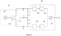
- Figure 5 shows an exemplary circuit diagram for a capacitive sensor comprising a sensor PCB as previously disclosed.
- the exemplary circuit may be used for determining a radial displacement of a rotor of an electrical machine in one dimension, for example. Other displacements (or rotations) may be measured with similar circuitries, for example.
- circuitry is explained in relation to the sensor PCB 20 of Figure 2a .
- circuitry is also applicable to other electrode configurations.
- FIG. 5 the capacitances formed by the shaft and the electrodes on the sensor PCB 20 are shown with references C 1 , C 2 , and C 3 ;
- C 1 represents a capacitance formed by one detection electrode 22 and the shaft;
- C 2 represents a capacitance formed by the other detection electrode 22 on the opposite side of the mounting hole 21 and the shaft;
- C 3 represents a capacitance formed by the four ground-connected electrodes 24 and the shaft.
- the circuitry in Figure 5 also comprises inductances L 1 and L 2 and resistances R 1 and R 2 . These resistances and inductances may be implemented as components soldered on the sensor PCB 20, for example. Capacitances C 1 and C 3 , inductance L 1 , and resistance R 1 form a first oscillator. Capacitances C 2 and C 3 , inductance L 2 , and resistance R 2 form a second oscillator.
- the senor comprises an AC signal generating circuitry 51.
- the circuitry comprises an AC signal generator 52 and a power divider 53.
- the AC signal generator 52 supplies the first and second oscillator with a high frequency AC signal through the power divider 53.
- the power divider 53 may be configured to minimise coupling between the first oscillator and the second oscillator.
- the sensor further comprises measurement circuitry 54 in Figure 5 .
- the measurement circuitry 54 is connected in parallel with the LC elements of the first and the second oscillators. Capacitances C 1 and C 3 , and inductance L 1 are the LC elements of the first oscillator; capacitances C 2 and C 3 , and inductance L 2 are the LC elements are of the second oscillator.
- the measurement circuitry 54 may comprise a filter and a detector for each of the oscillators, for example. In Figure 5 , the measurement circuitry 54 comprises a series connection of a filter 55 and a power detector 56 for each oscillator.
- the power (or amplitude) of a signal passing through the LC elements of the oscillator is responsive to the distance between the electrode 22 and the shaft. This may be utilised in detecting position of the shaft.
- the power detectors 56 measure a differences between the power (or amplitude) of the AC signal generated by the generator 52 and the powers (or amplitudes) of the signals passing through the LC elements.
- the measurement circuitry 54 may further comprise a differential amplifier 57 that measures the difference between powers (or signal amplitudes) detected by the power detectors 56.
- the resulting difference may be used as an indicator signal for a displacement or a rotation.
- the difference may be converted into a digital form by using an A/D converter, and used in a control system controlling the position of the shaft.
- the signals may also be measured separately and converted into a digital form, and the resulting displacement(s) and/or rotation(s) may be calculated in a computing device.
- the control system may be implemented on a computing device, for example.
- a computing device may be a CPU, a DSP, a PLD, or an FPGA, for example.
- the measurement circuitry may also be connected in series with the LC elements.
- the position may be estimated by measuring the AC signal power (amplitude) transferred through LC elements.
- the sensor PCB of the present disclosure may also be used for determining rotational angle (i.e. rotation ⁇ ' about a rotational axis of the shaft) or rotational speed.
- the electrically conducting part of the shaft mounted into the mounting hole of the sensor PCB, or an extension of the part, may be formed such that a capacitance generated by the part and a capacitor electrode on the sensor PCB is a non-constant function of the rotational angle ⁇ ' about the rotational axis (e.g. center axis) of the shaft.
- a non-constant capacitance as a function of the rotational angle can be produced by using a disc shaped extension similar to that described in Figure 2e .
- the capacitances between the radial electrodes 26 and the disc 27 can be made responsive to rotation ⁇ '. Detection of the rotation ⁇ ' may be decoupled from detections of rotations ⁇ ' and ⁇ '.
- the sensor PCB may have separate radial electrodes for forming a separate set of capacitances dedicated for detecting rotation ⁇ ', and the grooves may extend only a part of the radius of the disc, for example.
- the rotational angle may also be calculated from capacitances between the part and axial electrodes according to the disclosure.
- Axial electrodes used for detecting displacements of the shaft may also be used for detecting the rotational angle (or speed), for example.
- the part received into the mounting hole may be formed such that the capacitances between the axial electrodes and the conductive part act as a non-constant function of the rotational angle ⁇ '.
- the coupling between the detection of displacements and the detection of rotational angle may be minimized by using a conductive part mounted into the mounting hole having a non-circular cross section that is symmetrical with respect to the rotational axis.
- the part may be an attachable tip that has an elliptical cross section, for example.
- the part mounted into the mounting hole may have a (partial) coating resulting in a similar capacitance distribution.
- the capacitances formed between the electrodes and the part (and/or its extension) mounted into the mounting hole may be measured, and the displacements and/or rotations can be determined on the basis of the measured capacitances.
- the measurements of the capacitances may be implemented by using differential amplifiers as shown in Figure 5 , for example.
- the capacitances may also be measured separately and converted into a digital form, and the resulting displacement(s) and/or rotation(s) may be calculated in a computing device.
Landscapes
- Physics & Mathematics (AREA)
- General Physics & Mathematics (AREA)
- Engineering & Computer Science (AREA)
- Microelectronics & Electronic Packaging (AREA)
- Electromagnetism (AREA)
- Measurement Of Length, Angles, Or The Like Using Electric Or Magnetic Means (AREA)
- Transmission And Conversion Of Sensor Element Output (AREA)
Description
- The presented invention relates to motion and position sensors, and more particularly to the use of a capacitive sensor for sensing motion of a rotor of an electrical machine.
- Motion control systems typically require position feedback. For example, an active magnetic bearing control may require non-contact position sensors for feedback signal in order to be able to keep the position of a rotor within allowable tolerances. Position feedback can be achieved by eddy-current, inductive, capacitive or optical sensors, for example.
- Capacitive displacement sensors are frequently used in industry in a wide variety of applications including precise positioning, motion control, semiconductor processing, and assembly of equipment, thickness measurements, tools metrology and assembly line testing.
- In order to measure the distance between two conductive materials, a capacitive sensing system may utilise an equation for approximating capacitance C of a parallel-plate capacitor:

- Assuming that the area S and dielectric ε 0 εr of the material in the gap (usually air) remain constant, the capacitance value C reflects the changes in the distance r between the probe electrode and the target. The capacitive sensing system may be configured to measure the capacitance (or its changes) and therefore a distance (or motion). The current i in the capacitor is proportional to the capacitance value C and to the rate of change of voltage dv/dt across the capacitor (i = Cdv/dt).
- With capacitive displacement sensors, high-resolution measurements of the position and motion of a conductive target may be achieved. In the case of position measurement of a rotor of an electrical machine, a sensor tip may be mounted around the shaft for each measured dimension (degree of freedom).
- However, precise position and motion sensors may also have major disadvantages in industrial applications. The sensors may be expensive and complex to manufacture. They may be prone to mounting and assembly errors. The sensors may introduce significant delays to the measurements. Further, the sensors may have significant temperature dependence and they may be sensitive to noise. When interfacing indirectly with a motion controller or a rotor, for example, the sensor(s) may be susceptible to electromagnetic interferences and/or mechanical damage. Electromechanical runout of the rotor may also pose a major challenge for the control system.
- Patent publication
DE19808665C1 describes a steering column switch has a switch lever which is moved between a number of different switch positions via vertical, horizontal, axial and/or radial displacement, for controlling different switch functions. - Patent publication
EP1143225A2 describes a position sensor determines relative changes in position of a first member and a second member. - Patent publication
US5627316A describes a capacitive position sensor employs conventional printed circuit board technology to detect capacitive changes caused by the movement of a ball along conductive tracks. - An object of the present invention is to provide a method and an apparatus for implementing the method so as to alleviate the above disadvantages. The objects of the invention are achieved by a method and an apparatus which are characterized by what is stated in the independent claims. The preferred embodiments of the invention are disclosed in the dependent claims.
- A capacitive sensor that is capable of sensing position or motion of an electrically conductive shaft can be implemented by using a printed circuit board (PCB) having a mounting hole through which the shaft can be mounted.
- The printed circuit board may comprise at least one electrode (i.e. capacitor plate) formed to the PCB. The electrode forms a capacitor with the surface of the conducting shaft. Capacitance of the formed capacitor can be measured. Since the capacitance is responsive to the gap between the electrode and the surface of the shaft, the capacitance can be used for estimating the position of the shaft.
- An electrode surface of the electrode in/on the printed circuit board may extend parallel to a center axis of the mounting hole. The PCB may be configured such that a plurality of capacitor electrode formed to the PCB face the center axis, and form an annular shape around the center axis. The electrode surfaces may be formed by using a PCB hole plating process, for example. The edge of the mounting hole may be plated, or vias or plated holes may be used next to the mounting hole.
- The PCB may also comprise at least one capacitor electrode formed to the PCB where an electrode surface of the electrode extends along a plane that is perpendicular to the center axis of the mounting hole. The perpendicularly extending capacitor electrodes may be formed by using a PCB trace layer manufacturing process, such as etching.
- The disclosed sensor may be used to detect one- to six-dimensional motions, for example. In order to maximise the sensitivity, the sensor's measurement electronics may utilise the use of LC (or LRC) resonance, high frequency oscillating signals, filters and differential amplifiers, for example.
- The disclosed sensing method provides an affordable and robust approach for position sensing. It provides means for a precise non-contact measurement of the position and motion or of geometric properties of a conducting target. By manufacturing the sensor on a PCB, the manufacturing costs can be decreased considerably, the system integration can be increased, and system connectivity and interfacing can be improved.
- In the following the invention will be described in greater detail by means of preferred embodiments with reference to the attached drawings, in which
-
Figure 1a shows an exemplary shaft with six degrees of freedom; -
Figure 1b shows an exemplary arrangement according to the present disclosure; -
Figures 2a to 2e show an exemplary embodiment of a sensor PCB of the present disclosure; -
Figures 3a to 3c show exemplary embodiments of axial electrode implemented by using vias; -
Figures 4a to 4d show various exemplary implementations of shielding; and -
Figure 5 shows an exemplary circuit diagram for a capacitive sensor comprising a sensor PCB as previously disclosed. - The present disclosure discloses a method and sensor for sensing position (e.g. displacement) or motion of a shaft that comprises an electrically conducting part. The shaft may be a metal shaft of a rotor of an electrical machine, for example. The position or motion of an electrically conducting shaft or a shaft comprising an electrically conducting part can be accurately determined by using a sensor printed circuit board (PCB) that comprises a mounting hole configured to receive an electrically conducting part of the shaft therethrough and capacitor electrodes formed around the mounting hole.
- The sensor PCB can be used for detecting six degrees of freedom. With the PCB, translations (i.e. movements, displacements) of the shaft along three axes x, y, and z of Cartesian coordinate system and rotations α,β, and θ of the shaft around the axes can be detected, for example.
-
Figure 1a shows anexemplary shaft 10 with six degrees of freedom. Theshaft 10 has a cylindrical shape having a center axis A. InFigure 1a , the Cartesian coordinate system is arranged such that the z-axis coincides with the center axis A. The x- and y-axes extend along a plane that is perpendicular to the center axis A. InFigure 1a , the x- and y-axes are perpendicular to each other. - In
Figure 1a , z' refers to an axial displacement, i.e. to a displacement along the center axis A (also the z-axis inFigure 1a ). x' and y' refer to radial displacement, i.e. to displacements that extend along a plane that is perpendicular to the center axis A. InFigure 1a , displacements x' and y' extend along x- and y-axes, respectively. Therefore, they are perpendicular also with respect to each other. The shaft may be arranged to rotate about the center axis A. InFigure 1a , θ' refers to rotation of the shaft about the center axis A (also the z-axis inFigure 1a ). α' and β' refer to rotations about x- and y-axes, respectively. The same notation of the degrees of freedom is used in the following paragraphs. - In order to detect a displacement or a rotation of a shaft comprising an electrically conductive part, an arrangement according to the present disclosure may be used. An arrangement according to the present disclosure may comprise a sensor PCB according to the present disclosure, and a shaft with its electrically conductive part mounted to the mounting hole of the sensor PCB.
-
Figure 1b shows an exemplary embodiment of an arrangement according to the present disclosure. InFigure 1b , ashaft 10 comprises an electrically conductive part that is mounted to a mountinghole 11 of asensor PCB 12. - A sensor PCB according to the present disclosure may comprise at least one capacitor electrode facing the center axis of the mounting hole. The electrode may be formed to the sensor PCB so that an electrode surface of the electrode extends parallel to a center axis of the mounting hole thereby forming an axial electrode surface. The axial electrode surface may be formed by conductive plating on the inner wall of the mounting hole, for example.
-
Figures 2a to 2e show an exemplary embodiment of the disclosed sensor PCB. InFigure 2a , aPCB 20 comprises acircular mounting hole 21. The center axis B of the mountinghole 21 is shown as a dashed line. Since thehole 21 has a circular cross section inFigure 2a , the center axis B passes through the centre of the circular cross section. However, in more general terms, a center axis can be considered a center line that passes through a center of gravity of a cross section along the plane of the PCB, for example. - When a part of the shaft with an electrically conductive surface is mounted to the mounting hole, an axial electrode surface facing the shaft forms a capacitor together with the surface of the shaft that acts as an opposite electrode. The capacitance of this capacitor may be measured and radial displacement may be determined on the basis of the capacitance. The axial electrode surface may be formed by using a PCB hole plating process, for example.
- In
Figure 2a , thePCB 20 comprises a plurality ofcapacitor electrodes Figure 2b shows a cross section of one of theelectrodes PCB 20 around a conducting part of shaft received into the mountinghole 21, the sensing accuracy may be increased as the influence of noise and runout of the shaft can be minimised. - In
Figure 2a , thePCB 20 has eightcapacitor electrodes detector electrodes electrodes 24 may be used for electrically connecting the shaft to an analog signal ground of thePCB 20. InFigure 2a , thedetector electrodes electrodes 24 are arranged in an interleaved pattern. The number and relative positioning of electrodes on the PCB is not, however, limited to the configuration disclosed inFigure 2a . Other number of electrodes and other relative positioning of electrodes may also be used. - Each
electrode axial electrode surface 25 that extends parallel to a center axis of the mountinghole 21 and faces the center axis B. The axial electrode surfaces 25 are formed by conductive plating on the inner wall of the mountinghole 21. Theelectrodes - The
sensor PCB 20 may comprise multiple layers, as shown inFigures 2a and 2b . 12. A capacitive sensor may also comprise a plurality of such PCBs stacked on top of each other, as shown inFigure 2c . InFigure 2c , the plated edges of thePCBs 20 together form a largeraxial electrode surface 25. - In order to detect axial displacement of the shaft, for example, the PCB may also comprise at least one capacitor electrode formed to the printed circuit board such that the electrode comprises a radial electrode surface, i.e. a capacitor surface that extends along a plane that is perpendicular to the center axis of the mounting hole. The radial electrode surfaces may be formed by using a PCB trace layer manufacturing process, such as etching, for example.
- In
Figures 2a to 2c , theelectrodes Figure 2d . The separate radial electrode surfaces 26 may be used for detecting rotations α' and β', for example. - An arrangement for detecting rotations α' and/or β' may comprise a sensor PCB according to the present disclosure, and a shaft with an electrically conducting part mounted to the mounting hole. The PCB may comprise at least one capacitor electrode having a radial electrode surface, and the electrically conducting part of the shaft may be formed such that a capacitance formed by the part and the radial electrode surface is responsive to at least one of rotational angles about axes perpendicular to the rotational axis of the shaft.
-
Figure 2e shows a cross-sectional side view of an exemplary arrangement where thesensor PCB 20 hasradial electrodes 26 andaxial electrodes 25, and theshaft 28 is provided with a tip having a disc-shaped, electrically conductingextension 27. The disc shapedextension 27 forms capacitances with theradial electrodes 26. When theshaft 28 tilts (i.e. rotates about axis x), the distance between one of theradial electrodes 26 inFigure 2e and thedisc 27 decreases and the capacitance between them increases. At the same time, the distance between the otherradial electrode 26 inFigure 2e and thedisc 27 increases and the capacitance between them decreases. The difference between these two capacitances can be measured and the rotation α' can be determined on the basis of the difference. - In addition, displacement z' can also be determined by monitoring an average of the measured values of the capacitances.
- In
Figures 2a to 2e , the radial electrode surfaces are on the top and bottom layer of the PCB 20 (or the PCB stack). However, the radial electrode surfaces may be formed to the mid layers of the PCB as well. - In addition to the implementation of
axial electrodes 22 inFigures 2a and 2b , electrode surfaces that extend parallel to the center axis can be formed in various other ways. For example, the PCB may comprise at least one capacitor electrode hole, where at least part of the axial electrode surface is formed by conductive plating on the capacitor electrode hole. The capacitor electrode hole can be implemented by using PCB vias placed near the edge of the mounting hole, for example. -
Figures 3a to 3c show exemplary embodiments of axial electrode implemented by using vias.Figure 3a shows axial electrode surfaces ofcapacitor electrodes 31 formed by a plurality of side byside vias 32. Thevias 32 are plated with an electrically conducting material.Figure 3b shows a cross section of one of thevias 32. The part of the plating facing the mounting hole forms an axial electrode surface. - As shown in
Figure 3c the axial electrode surfaces may alternatively be formed by using a long platedslot 33 formed next to the edge of the mounting hole. - A capacitive sensor that is capable of sensing position or motion of an electrically conductive shaft may comprise a previously described sensor PCB (or a stack of the PCBs). In order to increase integration and decrease costs and noise susceptibility, the PCB may also be configured to accommodate electrical components implementing measurement circuitry of the capacitive sensor. Conductive traces forming connections between the components may also be formed on the sensor PCB. Detection signal generating circuitry and interfacing circuitry interfacing with the control system may also be mounted on the sensor PCB.
- The sensor PCB (or the PCB stack) may be enclosed in a conducting case in order to shield the sensor against some electromagnetic interference. The sensor PCB may also comprise at least one shielding conductive layer for minimising electromagnetic interference on the at least one capacitor electrode. For example, the top and bottom layers of the sensor PCB (or of the PCB stack) may also be conductive layers connected to a ground potential.
-
Figures 4a to 4d show various exemplary implementations of shielding.Figure 4a shows a cross section of an exemplary embodiment where anaxial electrode surface 41 is electrically shielded by a conductive top andbottom layer 42. - Conductive layers may also be used for minimising interference between electrodes.
Figure 4b shows an exemplary embodiment, where anaxial electrode surface 41 is separated fromradial electrodes 43 by aconductive layers 42 inside the PCB.Figure 4c shows an exemplary embodiment of a sensor PCB which may be used for detecting rotations α' and/or β' (i.e. tilt of the shaft). InFigure 4c , two separateaxial electrodes 41 have aground layer 42 between them. - Further, in order to improve shielding against electromagnetic, environmental or other interference, the capacitor electrodes may be at least partially coated with a protective coating, such as epoxy filling. The protective coating on the capacitor electrode may increase sensor accuracy by increasing the relative static permittivity compared to air. Thus, thickness of the protective coating may be configured for maximising sensor accuracy.
Figure 4d shows a cross section of an exemplary embodiment where anaxial electrode surface 41 is shielded by an epoxy filling 44 in addition to the conductive top andbottom layer 42. - Sensing position or motion of an electrically conductive shaft by using the disclosed sensor PCB can be implemented in various ways. One approach is to measure a time required to charge the capacitor to a certain voltage level or to measure a resonance frequency (time constant of a LRC or LC oscillator) of an oscillator formed by the capacitor together with resistive and/or inductive elements.
- Another approach is to apply a fixed-frequency AC voltage across a capacitive series divider. The first of the series-connected capacitances is known. Capacitance of the second capacitor may be calculated from a ratio between the capacitances, where the ratio between the capacitances corresponds with a ratio between the amplitudes of the output and input signals.
- Sensing accuracy may be increased by using a capacitance bridge configuration. For example, a pair of capacitor electrodes on opposite sides of the mounting hole may form two oscillators (LC or LRC). For example,
electrodes 22 inFigure 2a may form such a pair. Both oscillators may share a connection to an analog ground level through a capacitance formed by the shaft and capacitor electrode(s) on the PCB. InFigure 2a ,electrodes 24 form this capacitance. - Impedances of the oscillators depend on the position of the conducting shaft and the frequency of the used detection signal. The two oscillators may be supplied with a high-frequency alternating voltage. As the impedance changes responsive to the position, the positions may be estimated from the amplitudes of the generated AC signals of the two oscillators.
- When the shaft is at an equal distance from both of the capacitor electrodes (
e.g. electrodes 22 inFigure 2a ), the oscillators have the same impedances. Thus, the difference between signals of the oscillators is zero. However, if the shaft is closer to one electrode than the other, the signals have different amplitudes. A ratio between the amplitudes of the signals is responsive to the ratio of distances of the shaft with respect to the electrodes. Relative position and motion of the conducting shaft may be detected by measuring levels and changes of the current, voltages, or power of the oscillators, for example. - In order to measure the difference between the signals of the two oscillators, the signals may be demodulated and/or filtered and fed to a differential amplifier, for example. The signals may also be converted to a digital form, and the difference may be calculated in the digital domain.
-
Figure 5 shows an exemplary circuit diagram for a capacitive sensor comprising a sensor PCB as previously disclosed. The exemplary circuit may be used for determining a radial displacement of a rotor of an electrical machine in one dimension, for example. Other displacements (or rotations) may be measured with similar circuitries, for example. - In the following, the circuitry is explained in relation to the
sensor PCB 20 ofFigure 2a . However, the circuitry is also applicable to other electrode configurations. - In
Figure 5 , the capacitances formed by the shaft and the electrodes on thesensor PCB 20 are shown with references C 1 , C 2 , and C 3; C 1 represents a capacitance formed by onedetection electrode 22 and the shaft; C 2 represents a capacitance formed by theother detection electrode 22 on the opposite side of the mountinghole 21 and the shaft; and C 3 represents a capacitance formed by the four ground-connectedelectrodes 24 and the shaft. - The circuitry in
Figure 5 also comprises inductances L 1 and L 2 and resistances R 1 and R 2. These resistances and inductances may be implemented as components soldered on thesensor PCB 20, for example. Capacitances C 1 and C 3, inductance L 1, and resistance R 1 form a first oscillator. Capacitances C 2 and C 3, inductance L 2, and resistance R 2 form a second oscillator. - In
Figure 5 , the sensor comprises an ACsignal generating circuitry 51. The circuitry comprises anAC signal generator 52 and apower divider 53. TheAC signal generator 52 supplies the first and second oscillator with a high frequency AC signal through thepower divider 53. Thepower divider 53 may be configured to minimise coupling between the first oscillator and the second oscillator. - The sensor further comprises
measurement circuitry 54 inFigure 5 . Themeasurement circuitry 54 is connected in parallel with the LC elements of the first and the second oscillators. Capacitances C 1 and C 3, and inductance L 1 are the LC elements of the first oscillator; capacitances C 2 and C 3, and inductance L 2 are the LC elements are of the second oscillator. Themeasurement circuitry 54 may comprise a filter and a detector for each of the oscillators, for example. InFigure 5 , themeasurement circuitry 54 comprises a series connection of afilter 55 and apower detector 56 for each oscillator. - For each oscillator, the power (or amplitude) of a signal passing through the LC elements of the oscillator is responsive to the distance between the
electrode 22 and the shaft. This may be utilised in detecting position of the shaft. InFigure 5 , thepower detectors 56 measure a differences between the power (or amplitude) of the AC signal generated by thegenerator 52 and the powers (or amplitudes) of the signals passing through the LC elements. - In order to determine the relative location, the
measurement circuitry 54 may further comprise adifferential amplifier 57 that measures the difference between powers (or signal amplitudes) detected by thepower detectors 56. - The resulting difference may be used as an indicator signal for a displacement or a rotation. The difference may be converted into a digital form by using an A/D converter, and used in a control system controlling the position of the shaft.
- Alternatively, the signals may also be measured separately and converted into a digital form, and the resulting displacement(s) and/or rotation(s) may be calculated in a computing device.
- The control system may be implemented on a computing device, for example. A computing device may be a CPU, a DSP, a PLD, or an FPGA, for example.
- The measurement circuitry may also be connected in series with the LC elements. The position may be estimated by measuring the AC signal power (amplitude) transferred through LC elements.
- The sensor PCB of the present disclosure may also be used for determining rotational angle (i.e. rotation θ' about a rotational axis of the shaft) or rotational speed.
- The electrically conducting part of the shaft mounted into the mounting hole of the sensor PCB, or an extension of the part, may be formed such that a capacitance generated by the part and a capacitor electrode on the sensor PCB is a non-constant function of the rotational angle θ' about the rotational axis (e.g. center axis) of the shaft.
- For example, a non-constant capacitance as a function of the rotational angle can be produced by using a disc shaped extension similar to that described in
Figure 2e . By adding radially extending grooves to face of thedisc 27 facing theradial electrodes 26 inFigure 2e , for example, the capacitances between theradial electrodes 26 and thedisc 27 can be made responsive to rotation θ'. Detection of the rotation θ' may be decoupled from detections of rotations α' and β'. The sensor PCB may have separate radial electrodes for forming a separate set of capacitances dedicated for detecting rotation θ', and the grooves may extend only a part of the radius of the disc, for example. - The rotational angle may also be calculated from capacitances between the part and axial electrodes according to the disclosure. Axial electrodes used for detecting displacements of the shaft may also be used for detecting the rotational angle (or speed), for example. The part received into the mounting hole may be formed such that the capacitances between the axial electrodes and the conductive part act as a non-constant function of the rotational angle θ'.
- The coupling between the detection of displacements and the detection of rotational angle may be minimized by using a conductive part mounted into the mounting hole having a non-circular cross section that is symmetrical with respect to the rotational axis. The part may be an attachable tip that has an elliptical cross section, for example. Alternatively, the part mounted into the mounting hole may have a (partial) coating resulting in a similar capacitance distribution.
- The capacitances formed between the electrodes and the part (and/or its extension) mounted into the mounting hole may be measured, and the displacements and/or rotations can be determined on the basis of the measured capacitances. The measurements of the capacitances may be implemented by using differential amplifiers as shown in
Figure 5 , for example. The capacitances may also be measured separately and converted into a digital form, and the resulting displacement(s) and/or rotation(s) may be calculated in a computing device. - It will be obvious to a person skilled in the art that the inventive concept can be implemented in various ways. The invention and its embodiments are not limited to the examples described above but may vary within the scope of the claims.
Claims (15)
- A printed circuit board (PCB) (20) for a capacitive sensor configured to sense position or motion of a shaft comprising an electrically conducting part, characterized in that the printed circuit board (20) comprises
a mounting hole (21) configured to receive the electrically conducting part therethrough,
at least one capacitor electrode (22, 23, 24) formed to the printed circuit board (20), wherein an electrode surface (25) of the electrode (22, 23, 24) extends parallel to a center axis of the mounting hole (21) and faces the center axis. - A printed circuit board (20) according to claim 1, wherein the electrode surface (25) is a surface formed by using a PCB hole plating process.
- A printed circuit board (20) according to claim 2, wherein at least part of the electrode surface (25) is formed by conductive plating on the inner wall of the mounting hole.
- A printed circuit board (20) according to claim 2, further comprising at least one capacitor electrode hole (32), wherein at least part of the electrode surface (31) is formed by conductive plating on the at least one capacitor electrode hole (32).
- A printed circuit board (20) according to any one of preceding claims, comprising a plurality of capacitor electrodes (22, 23, 24) formed to the printed circuit board, wherein electrode surfaces (25) of the electrodes (22, 23, 24) extend parallel to a center axis of the mounting hole and face the center axis, and wherein the electrodes (22, 23, 24) form an annular shape around the center axis.
- A printed circuit board (20) according to any one of preceding claims, wherein the printed circuit board (20) is configured to accommodate electrical components implementing measurement circuitry of a capacitive sensor.
- A printed circuit board according to any one of preceding claims, wherein the printed circuit board comprises at least one shielding conductive layer (42) for minimising electromagnetic interference on the at least one capacitor electrode (41).
- A printed circuit board according to any one of preceding claims, wherein the at least one capacitor electrode (41) is at least partially coated with protective coating (44), such as epoxy filling.
- A printed circuit board (20) according to any one of preceding claims, comprising
at least one capacitor electrode (22, 23, 24) having a radial electrode surface (26) extending along a plane that is perpendicular to the center axis of the mounting hole (21). - A capacitive sensor comprising a printed circuit board (PCB) according to any one of preceding claims.
- A capacitive sensor according to claim 10, comprising a plurality of printed circuit boards (PCB) according to any one of claims 1 to 9 stacked on top of each other.
- A method for sensing position or motion of a shaft comprising an electrically conducting part, wherein the method comprises steps of
mounting the electrically part to a mounting hole (21) of a printed circuit board (20) according to any one of claims 1 to 9, and
sensing the position or the motion of the shaft by using the printed circuit board (20). - An arrangement comprising
a printed circuit board (20) according to any one of claims 1 to 9, and
a shaft comprising an electrically conductive part mounted to the mounting hole (21) of the printed circuit board (20). - An arrangement according to claim 13, wherein the printed circuit board (20) comprises
at least one capacitor electrode (22, 23, 24) formed to the printed circuit board (20) has a radial electrode surface (26) of the electrode that extends along a plane that is perpendicular to the center axis of the mounting hole (21), and
the part mounted to the mounting hole (21) is formed such that a capacitance formed by the part and the radial electrode surface (26) is responsive to at least one of rotational angles about axes perpendicular to the rotational axis of the shaft. - An arrangement according to claim 13 or 14, wherein the part mounted to the mounting hole (21) is formed such that a capacitance formed by the part and the at least one capacitor electrode (22, 23, 24) is responsive to the rotational angle about the rotational axis of the shaft.
Priority Applications (4)
| Application Number | Priority Date | Filing Date | Title |
|---|---|---|---|
| EP14159872.2A EP2918964B1 (en) | 2014-03-14 | 2014-03-14 | Method, sensor, and printed circuit board for sensing position or motion of a shaft |
| CN201580013472.3A CN106415190B (en) | 2014-03-14 | 2015-03-13 | Method for sensing the position or movement of a shaft, sensor and printed circuit board |
| PCT/EP2015/055253 WO2015136063A1 (en) | 2014-03-14 | 2015-03-13 | Method, sensor, and printed circuit board for sensing position or motion of a shaft |
| US15/126,209 US9784596B2 (en) | 2014-03-14 | 2015-03-13 | Method, sensor, and printed circuit board for sensing position or motion of a shaft |
Applications Claiming Priority (1)
| Application Number | Priority Date | Filing Date | Title |
|---|---|---|---|
| EP14159872.2A EP2918964B1 (en) | 2014-03-14 | 2014-03-14 | Method, sensor, and printed circuit board for sensing position or motion of a shaft |
Publications (2)
| Publication Number | Publication Date |
|---|---|
| EP2918964A1 EP2918964A1 (en) | 2015-09-16 |
| EP2918964B1 true EP2918964B1 (en) | 2020-05-13 |
Family
ID=50336100
Family Applications (1)
| Application Number | Title | Priority Date | Filing Date |
|---|---|---|---|
| EP14159872.2A Active EP2918964B1 (en) | 2014-03-14 | 2014-03-14 | Method, sensor, and printed circuit board for sensing position or motion of a shaft |
Country Status (4)
| Country | Link |
|---|---|
| US (1) | US9784596B2 (en) |
| EP (1) | EP2918964B1 (en) |
| CN (1) | CN106415190B (en) |
| WO (1) | WO2015136063A1 (en) |
Cited By (1)
| Publication number | Priority date | Publication date | Assignee | Title |
|---|---|---|---|---|
| EP4092398A1 (en) | 2021-05-20 | 2022-11-23 | ABB Schweiz AG | Arrangement, method, and computer program for estimating radial loading of rotating shaft on antifriction bearing |
Families Citing this family (9)
| Publication number | Priority date | Publication date | Assignee | Title |
|---|---|---|---|---|
| US9810314B2 (en) | 2015-02-25 | 2017-11-07 | Kongsberg Driveline Systems I, Inc. | Rotary shifter assembly |
| WO2017142533A1 (en) * | 2016-02-17 | 2017-08-24 | Kongsberg Driveline Systems I, Inc. | Assembly and method of sensing movement of a shaft member |
| WO2018205261A1 (en) | 2017-05-12 | 2018-11-15 | Texas Instruments Incorporated | Methods and apparatus to determine a position of a rotatable shaft of a motor |
| EP3622256A4 (en) | 2017-05-12 | 2020-05-13 | Texas Instruments Incorporated | Capacitive-sensing rotary encoders and methods |
| EP3704464B1 (en) | 2017-11-03 | 2021-03-31 | ABB Schweiz AG | Arrangement for monitoring antifriction bearing of rotating shaft of rotating electric machine |
| IT201800005159A1 (en) * | 2018-05-08 | 2019-11-08 | CAPACITIVE POSITION TRANSDUCER AND RELATED JOYSTICK DEVICE AND CONTROL METHOD. | |
| WO2020069749A1 (en) | 2018-10-05 | 2020-04-09 | Abb Schweiz Ag | Arrangement and method for measuring temperature of rotating shaft |
| US11326906B2 (en) * | 2018-11-23 | 2022-05-10 | Samsung Electro-Mechanics Co., Ltd. | Apparatus for sensing rotating body |
| WO2023193864A1 (en) * | 2022-04-08 | 2023-10-12 | Coloplast A/S | Capacitive sensor assembly |
Family Cites Families (8)
| Publication number | Priority date | Publication date | Assignee | Title |
|---|---|---|---|---|
| US5627316A (en) * | 1995-03-24 | 1997-05-06 | Sigma-Delta N.V. | Capacitive inclination and acceleration sensor |
| DE19808665C1 (en) * | 1998-03-02 | 1999-08-19 | Siemens Ag | Automobile steering column switch |
| US6480007B1 (en) * | 2000-04-05 | 2002-11-12 | Trw Inc. | Capacitive sensor excitation techniques |
| KR100346266B1 (en) * | 2000-06-01 | 2002-07-26 | 엘지전자주식회사 | Touch Switch Having Electroluminescent Sheet For Backlighting |
| JP4791766B2 (en) * | 2005-05-30 | 2011-10-12 | 株式会社東芝 | Semiconductor device using MEMS technology |
| US9001040B2 (en) * | 2010-06-02 | 2015-04-07 | Synaptics Incorporated | Integrated fingerprint sensor and navigation device |
| CN102095356B (en) * | 2010-11-09 | 2012-06-27 | 浙江大学 | Method and device for measuring five degrees of freedom of main shaft based on cylindrical surface capacitor sensor |
| US8453506B2 (en) * | 2010-11-29 | 2013-06-04 | General Electric Company | Spring mounting element for an accelerometer |
-
2014
- 2014-03-14 EP EP14159872.2A patent/EP2918964B1/en active Active
-
2015
- 2015-03-13 CN CN201580013472.3A patent/CN106415190B/en active Active
- 2015-03-13 US US15/126,209 patent/US9784596B2/en active Active
- 2015-03-13 WO PCT/EP2015/055253 patent/WO2015136063A1/en active Application Filing
Non-Patent Citations (1)
| Title |
|---|
| None * |
Cited By (1)
| Publication number | Priority date | Publication date | Assignee | Title |
|---|---|---|---|---|
| EP4092398A1 (en) | 2021-05-20 | 2022-11-23 | ABB Schweiz AG | Arrangement, method, and computer program for estimating radial loading of rotating shaft on antifriction bearing |
Also Published As
| Publication number | Publication date |
|---|---|
| EP2918964A1 (en) | 2015-09-16 |
| US20170089734A1 (en) | 2017-03-30 |
| WO2015136063A1 (en) | 2015-09-17 |
| US9784596B2 (en) | 2017-10-10 |
| CN106415190A (en) | 2017-02-15 |
| CN106415190B (en) | 2020-06-26 |
Similar Documents
| Publication | Publication Date | Title |
|---|---|---|
| EP2918964B1 (en) | Method, sensor, and printed circuit board for sensing position or motion of a shaft | |
| EP3702738B1 (en) | Method for increasing the position measurement accuracy using inductive position sensor | |
| US5764066A (en) | Object locating system | |
| JP4198306B2 (en) | Capacitive sensor, semiconductor manufacturing apparatus, and liquid crystal display element manufacturing apparatus | |
| JP2018031777A (en) | Winding configuration of electromagnetic induction type encoder | |
| US6828806B1 (en) | Electrostatic capacitance sensor, electrostatic capacitance sensor component, object mounting body and object mounting apparatus | |
| US9035662B2 (en) | Method and device for accurate capacitive measured value acquisition | |
| US9441990B2 (en) | Capacitive rotary position encoder | |
| EP3221667B1 (en) | Inductive position detector | |
| US20070205775A1 (en) | Device , Sensor Arrangement and Method for the Capacitive Position Finding of a Target Object | |
| EP3479072B1 (en) | Inductive position detector | |
| JPH05215506A (en) | Capacitive position sensor | |
| CN107209874B (en) | Non-contact position/distance sensor with artificial neural network and method of operating the same | |
| US7302762B1 (en) | Plate type capacitive sensor for five-dimensional displacement measurement | |
| JP2018200196A (en) | Gap sensor and method for measuring gap | |
| JP6692459B2 (en) | Linear displacement sensor with tilt tolerance | |
| JP2001091205A (en) | Object-loading apparatus | |
| Baby et al. | A simple analog front-end circuit for grounded capacitive sensors with offset capacitance | |
| CN103162717A (en) | Capacitive non-contact angular position sensor | |
| KR101952327B1 (en) | Capacitive sensor and method for detecting a number of objects | |
| US20200041311A1 (en) | Capacitive distance sensor | |
| JP4872989B2 (en) | Capacitance type sensor component, object mounting body, semiconductor manufacturing apparatus, and liquid crystal display element manufacturing apparatus | |
| CN109596099B (en) | Inclination angle sensor of similar rotary transformer | |
| Clergeot et al. | Electrical proximity sensors | |
| KR101701318B1 (en) | A capacitive sensing unit of plan position measuring device |
Legal Events
| Date | Code | Title | Description |
|---|---|---|---|
| PUAI | Public reference made under article 153(3) epc to a published international application that has entered the european phase |
Free format text: ORIGINAL CODE: 0009012 |
|
| AK | Designated contracting states |
Kind code of ref document: A1 Designated state(s): AL AT BE BG CH CY CZ DE DK EE ES FI FR GB GR HR HU IE IS IT LI LT LU LV MC MK MT NL NO PL PT RO RS SE SI SK SM TR |
|
| AX | Request for extension of the european patent |
Extension state: BA ME |
|
| RBV | Designated contracting states (corrected) |
Designated state(s): AL AT BE BG CH CY CZ DE DK EE ES FI FR GB GR HR HU IE IS IT LI LT LU LV MC MK MT NL NO PL PT RO RS SE SI SK SM TR |
|
| 17P | Request for examination filed |
Effective date: 20160308 |
|
| RAP1 | Party data changed (applicant data changed or rights of an application transferred) |
Owner name: ABB SCHWEIZ AG |
|
| REG | Reference to a national code |
Ref country code: DE Ref legal event code: R079 Ref document number: 602014065346 Country of ref document: DE Free format text: PREVIOUS MAIN CLASS: G01B0007060000 Ipc: G01B0007004000 |
|
| GRAP | Despatch of communication of intention to grant a patent |
Free format text: ORIGINAL CODE: EPIDOSNIGR1 |
|
| STAA | Information on the status of an ep patent application or granted ep patent |
Free format text: STATUS: GRANT OF PATENT IS INTENDED |
|
| INTG | Intention to grant announced |
Effective date: 20191206 |
|
| RIC1 | Information provided on ipc code assigned before grant |
Ipc: G01D 11/24 20060101ALI20191122BHEP Ipc: H05K 3/42 20060101ALI20191122BHEP Ipc: H05K 1/16 20060101ALI20191122BHEP Ipc: G01B 7/004 20060101AFI20191122BHEP Ipc: G01D 5/24 20060101ALI20191122BHEP |
|
| GRAS | Grant fee paid |
Free format text: ORIGINAL CODE: EPIDOSNIGR3 |
|
| GRAA | (expected) grant |
Free format text: ORIGINAL CODE: 0009210 |
|
| STAA | Information on the status of an ep patent application or granted ep patent |
Free format text: STATUS: THE PATENT HAS BEEN GRANTED |
|
| RAP1 | Party data changed (applicant data changed or rights of an application transferred) |
Owner name: ABB SCHWEIZ AG |
|
| AK | Designated contracting states |
Kind code of ref document: B1 Designated state(s): AL AT BE BG CH CY CZ DE DK EE ES FI FR GB GR HR HU IE IS IT LI LT LU LV MC MK MT NL NO PL PT RO RS SE SI SK SM TR |
|
| REG | Reference to a national code |
Ref country code: GB Ref legal event code: FG4D |
|
| REG | Reference to a national code |
Ref country code: CH Ref legal event code: EP |
|
| REG | Reference to a national code |
Ref country code: DE Ref legal event code: R096 Ref document number: 602014065346 Country of ref document: DE |
|
| REG | Reference to a national code |
Ref country code: AT Ref legal event code: REF Ref document number: 1270854 Country of ref document: AT Kind code of ref document: T Effective date: 20200615 |
|
| REG | Reference to a national code |
Ref country code: LT Ref legal event code: MG4D |
|
| REG | Reference to a national code |
Ref country code: NL Ref legal event code: MP Effective date: 20200513 |
|
| PG25 | Lapsed in a contracting state [announced via postgrant information from national office to epo] |
Ref country code: IS Free format text: LAPSE BECAUSE OF FAILURE TO SUBMIT A TRANSLATION OF THE DESCRIPTION OR TO PAY THE FEE WITHIN THE PRESCRIBED TIME-LIMIT Effective date: 20200913 Ref country code: FI Free format text: LAPSE BECAUSE OF FAILURE TO SUBMIT A TRANSLATION OF THE DESCRIPTION OR TO PAY THE FEE WITHIN THE PRESCRIBED TIME-LIMIT Effective date: 20200513 Ref country code: PT Free format text: LAPSE BECAUSE OF FAILURE TO SUBMIT A TRANSLATION OF THE DESCRIPTION OR TO PAY THE FEE WITHIN THE PRESCRIBED TIME-LIMIT Effective date: 20200914 Ref country code: LT Free format text: LAPSE BECAUSE OF FAILURE TO SUBMIT A TRANSLATION OF THE DESCRIPTION OR TO PAY THE FEE WITHIN THE PRESCRIBED TIME-LIMIT Effective date: 20200513 Ref country code: SE Free format text: LAPSE BECAUSE OF FAILURE TO SUBMIT A TRANSLATION OF THE DESCRIPTION OR TO PAY THE FEE WITHIN THE PRESCRIBED TIME-LIMIT Effective date: 20200513 Ref country code: NO Free format text: LAPSE BECAUSE OF FAILURE TO SUBMIT A TRANSLATION OF THE DESCRIPTION OR TO PAY THE FEE WITHIN THE PRESCRIBED TIME-LIMIT Effective date: 20200813 Ref country code: GR Free format text: LAPSE BECAUSE OF FAILURE TO SUBMIT A TRANSLATION OF THE DESCRIPTION OR TO PAY THE FEE WITHIN THE PRESCRIBED TIME-LIMIT Effective date: 20200814 |
|
| PG25 | Lapsed in a contracting state [announced via postgrant information from national office to epo] |
Ref country code: RS Free format text: LAPSE BECAUSE OF FAILURE TO SUBMIT A TRANSLATION OF THE DESCRIPTION OR TO PAY THE FEE WITHIN THE PRESCRIBED TIME-LIMIT Effective date: 20200513 Ref country code: BG Free format text: LAPSE BECAUSE OF FAILURE TO SUBMIT A TRANSLATION OF THE DESCRIPTION OR TO PAY THE FEE WITHIN THE PRESCRIBED TIME-LIMIT Effective date: 20200813 Ref country code: HR Free format text: LAPSE BECAUSE OF FAILURE TO SUBMIT A TRANSLATION OF THE DESCRIPTION OR TO PAY THE FEE WITHIN THE PRESCRIBED TIME-LIMIT Effective date: 20200513 Ref country code: LV Free format text: LAPSE BECAUSE OF FAILURE TO SUBMIT A TRANSLATION OF THE DESCRIPTION OR TO PAY THE FEE WITHIN THE PRESCRIBED TIME-LIMIT Effective date: 20200513 |
|
| REG | Reference to a national code |
Ref country code: AT Ref legal event code: MK05 Ref document number: 1270854 Country of ref document: AT Kind code of ref document: T Effective date: 20200513 |
|
| PG25 | Lapsed in a contracting state [announced via postgrant information from national office to epo] |
Ref country code: AL Free format text: LAPSE BECAUSE OF FAILURE TO SUBMIT A TRANSLATION OF THE DESCRIPTION OR TO PAY THE FEE WITHIN THE PRESCRIBED TIME-LIMIT Effective date: 20200513 Ref country code: NL Free format text: LAPSE BECAUSE OF FAILURE TO SUBMIT A TRANSLATION OF THE DESCRIPTION OR TO PAY THE FEE WITHIN THE PRESCRIBED TIME-LIMIT Effective date: 20200513 |
|
| PG25 | Lapsed in a contracting state [announced via postgrant information from national office to epo] |
Ref country code: EE Free format text: LAPSE BECAUSE OF FAILURE TO SUBMIT A TRANSLATION OF THE DESCRIPTION OR TO PAY THE FEE WITHIN THE PRESCRIBED TIME-LIMIT Effective date: 20200513 Ref country code: AT Free format text: LAPSE BECAUSE OF FAILURE TO SUBMIT A TRANSLATION OF THE DESCRIPTION OR TO PAY THE FEE WITHIN THE PRESCRIBED TIME-LIMIT Effective date: 20200513 Ref country code: DK Free format text: LAPSE BECAUSE OF FAILURE TO SUBMIT A TRANSLATION OF THE DESCRIPTION OR TO PAY THE FEE WITHIN THE PRESCRIBED TIME-LIMIT Effective date: 20200513 Ref country code: SM Free format text: LAPSE BECAUSE OF FAILURE TO SUBMIT A TRANSLATION OF THE DESCRIPTION OR TO PAY THE FEE WITHIN THE PRESCRIBED TIME-LIMIT Effective date: 20200513 Ref country code: IT Free format text: LAPSE BECAUSE OF FAILURE TO SUBMIT A TRANSLATION OF THE DESCRIPTION OR TO PAY THE FEE WITHIN THE PRESCRIBED TIME-LIMIT Effective date: 20200513 Ref country code: CZ Free format text: LAPSE BECAUSE OF FAILURE TO SUBMIT A TRANSLATION OF THE DESCRIPTION OR TO PAY THE FEE WITHIN THE PRESCRIBED TIME-LIMIT Effective date: 20200513 Ref country code: RO Free format text: LAPSE BECAUSE OF FAILURE TO SUBMIT A TRANSLATION OF THE DESCRIPTION OR TO PAY THE FEE WITHIN THE PRESCRIBED TIME-LIMIT Effective date: 20200513 Ref country code: ES Free format text: LAPSE BECAUSE OF FAILURE TO SUBMIT A TRANSLATION OF THE DESCRIPTION OR TO PAY THE FEE WITHIN THE PRESCRIBED TIME-LIMIT Effective date: 20200513 |
|
| REG | Reference to a national code |
Ref country code: DE Ref legal event code: R097 Ref document number: 602014065346 Country of ref document: DE |
|
| PG25 | Lapsed in a contracting state [announced via postgrant information from national office to epo] |
Ref country code: SK Free format text: LAPSE BECAUSE OF FAILURE TO SUBMIT A TRANSLATION OF THE DESCRIPTION OR TO PAY THE FEE WITHIN THE PRESCRIBED TIME-LIMIT Effective date: 20200513 Ref country code: PL Free format text: LAPSE BECAUSE OF FAILURE TO SUBMIT A TRANSLATION OF THE DESCRIPTION OR TO PAY THE FEE WITHIN THE PRESCRIBED TIME-LIMIT Effective date: 20200513 |
|
| PLBE | No opposition filed within time limit |
Free format text: ORIGINAL CODE: 0009261 |
|
| STAA | Information on the status of an ep patent application or granted ep patent |
Free format text: STATUS: NO OPPOSITION FILED WITHIN TIME LIMIT |
|
| 26N | No opposition filed |
Effective date: 20210216 |
|
| PG25 | Lapsed in a contracting state [announced via postgrant information from national office to epo] |
Ref country code: SI Free format text: LAPSE BECAUSE OF FAILURE TO SUBMIT A TRANSLATION OF THE DESCRIPTION OR TO PAY THE FEE WITHIN THE PRESCRIBED TIME-LIMIT Effective date: 20200513 |
|
| PG25 | Lapsed in a contracting state [announced via postgrant information from national office to epo] |
Ref country code: MC Free format text: LAPSE BECAUSE OF FAILURE TO SUBMIT A TRANSLATION OF THE DESCRIPTION OR TO PAY THE FEE WITHIN THE PRESCRIBED TIME-LIMIT Effective date: 20200513 |
|
| REG | Reference to a national code |
Ref country code: CH Ref legal event code: PL |
|
| REG | Reference to a national code |
Ref country code: BE Ref legal event code: MM Effective date: 20210331 |
|
| PG25 | Lapsed in a contracting state [announced via postgrant information from national office to epo] |
Ref country code: IE Free format text: LAPSE BECAUSE OF NON-PAYMENT OF DUE FEES Effective date: 20210314 Ref country code: CH Free format text: LAPSE BECAUSE OF NON-PAYMENT OF DUE FEES Effective date: 20210331 Ref country code: LI Free format text: LAPSE BECAUSE OF NON-PAYMENT OF DUE FEES Effective date: 20210331 Ref country code: LU Free format text: LAPSE BECAUSE OF NON-PAYMENT OF DUE FEES Effective date: 20210314 |
|
| PG25 | Lapsed in a contracting state [announced via postgrant information from national office to epo] |
Ref country code: BE Free format text: LAPSE BECAUSE OF NON-PAYMENT OF DUE FEES Effective date: 20210331 |
|
| PG25 | Lapsed in a contracting state [announced via postgrant information from national office to epo] |
Ref country code: HU Free format text: LAPSE BECAUSE OF FAILURE TO SUBMIT A TRANSLATION OF THE DESCRIPTION OR TO PAY THE FEE WITHIN THE PRESCRIBED TIME-LIMIT; INVALID AB INITIO Effective date: 20140314 |
|
| PG25 | Lapsed in a contracting state [announced via postgrant information from national office to epo] |
Ref country code: CY Free format text: LAPSE BECAUSE OF FAILURE TO SUBMIT A TRANSLATION OF THE DESCRIPTION OR TO PAY THE FEE WITHIN THE PRESCRIBED TIME-LIMIT Effective date: 20200513 |
|
| PG25 | Lapsed in a contracting state [announced via postgrant information from national office to epo] |
Ref country code: MK Free format text: LAPSE BECAUSE OF FAILURE TO SUBMIT A TRANSLATION OF THE DESCRIPTION OR TO PAY THE FEE WITHIN THE PRESCRIBED TIME-LIMIT Effective date: 20200513 |
|
| PGFP | Annual fee paid to national office [announced via postgrant information from national office to epo] |
Ref country code: DE Payment date: 20240320 Year of fee payment: 11 Ref country code: GB Payment date: 20240320 Year of fee payment: 11 |
|
| PGFP | Annual fee paid to national office [announced via postgrant information from national office to epo] |
Ref country code: FR Payment date: 20240328 Year of fee payment: 11 |