EP3957869A1 - Method and assembly for testing screw connections - Google Patents
Method and assembly for testing screw connections Download PDFInfo
- Publication number
- EP3957869A1 EP3957869A1 EP20191535.2A EP20191535A EP3957869A1 EP 3957869 A1 EP3957869 A1 EP 3957869A1 EP 20191535 A EP20191535 A EP 20191535A EP 3957869 A1 EP3957869 A1 EP 3957869A1
- Authority
- EP
- European Patent Office
- Prior art keywords
- carrier plate
- contact surface
- screw
- signal
- connection
- Prior art date
- Legal status (The legal status is an assumption and is not a legal conclusion. Google has not performed a legal analysis and makes no representation as to the accuracy of the status listed.)
- Withdrawn
Links
- 238000000034 method Methods 0.000 title claims abstract description 20
- 238000012360 testing method Methods 0.000 title description 5
- 238000011156 evaluation Methods 0.000 claims description 17
- 239000004020 conductor Substances 0.000 claims description 5
- 230000008054 signal transmission Effects 0.000 abstract description 6
- 238000004519 manufacturing process Methods 0.000 description 10
- RYGMFSIKBFXOCR-UHFFFAOYSA-N Copper Chemical compound [Cu] RYGMFSIKBFXOCR-UHFFFAOYSA-N 0.000 description 5
- 229910052802 copper Inorganic materials 0.000 description 5
- 239000010949 copper Substances 0.000 description 5
- 230000002349 favourable effect Effects 0.000 description 3
- 238000005476 soldering Methods 0.000 description 3
- 241001271959 Anablepidae Species 0.000 description 2
- 238000004026 adhesive bonding Methods 0.000 description 2
- 230000005540 biological transmission Effects 0.000 description 2
- 239000011248 coating agent Substances 0.000 description 2
- 238000000576 coating method Methods 0.000 description 2
- 230000002950 deficient Effects 0.000 description 2
- 238000003780 insertion Methods 0.000 description 2
- 230000037431 insertion Effects 0.000 description 2
- 238000005259 measurement Methods 0.000 description 2
- 238000003672 processing method Methods 0.000 description 2
- 230000001419 dependent effect Effects 0.000 description 1
- 238000011161 development Methods 0.000 description 1
- 230000020169 heat generation Effects 0.000 description 1
- 230000001771 impaired effect Effects 0.000 description 1
- 238000007689 inspection Methods 0.000 description 1
- 238000009434 installation Methods 0.000 description 1
- 239000011810 insulating material Substances 0.000 description 1
- 238000012423 maintenance Methods 0.000 description 1
- 230000003287 optical effect Effects 0.000 description 1
- 238000007747 plating Methods 0.000 description 1
- 238000003825 pressing Methods 0.000 description 1
- 238000012795 verification Methods 0.000 description 1
Images
Classifications
-
- F—MECHANICAL ENGINEERING; LIGHTING; HEATING; WEAPONS; BLASTING
- F16—ENGINEERING ELEMENTS AND UNITS; GENERAL MEASURES FOR PRODUCING AND MAINTAINING EFFECTIVE FUNCTIONING OF MACHINES OR INSTALLATIONS; THERMAL INSULATION IN GENERAL
- F16B—DEVICES FOR FASTENING OR SECURING CONSTRUCTIONAL ELEMENTS OR MACHINE PARTS TOGETHER, e.g. NAILS, BOLTS, CIRCLIPS, CLAMPS, CLIPS OR WEDGES; JOINTS OR JOINTING
- F16B5/00—Joining sheets or plates, e.g. panels, to one another or to strips or bars parallel to them
- F16B5/02—Joining sheets or plates, e.g. panels, to one another or to strips or bars parallel to them by means of fastening members using screw-thread
-
- F—MECHANICAL ENGINEERING; LIGHTING; HEATING; WEAPONS; BLASTING
- F16—ENGINEERING ELEMENTS AND UNITS; GENERAL MEASURES FOR PRODUCING AND MAINTAINING EFFECTIVE FUNCTIONING OF MACHINES OR INSTALLATIONS; THERMAL INSULATION IN GENERAL
- F16B—DEVICES FOR FASTENING OR SECURING CONSTRUCTIONAL ELEMENTS OR MACHINE PARTS TOGETHER, e.g. NAILS, BOLTS, CIRCLIPS, CLAMPS, CLIPS OR WEDGES; JOINTS OR JOINTING
- F16B41/00—Measures against loss of bolts, nuts, or pins; Measures against unauthorised operation of bolts, nuts or pins
- F16B41/002—Measures against loss of bolts, nuts or pins
-
- F—MECHANICAL ENGINEERING; LIGHTING; HEATING; WEAPONS; BLASTING
- F16—ENGINEERING ELEMENTS AND UNITS; GENERAL MEASURES FOR PRODUCING AND MAINTAINING EFFECTIVE FUNCTIONING OF MACHINES OR INSTALLATIONS; THERMAL INSULATION IN GENERAL
- F16B—DEVICES FOR FASTENING OR SECURING CONSTRUCTIONAL ELEMENTS OR MACHINE PARTS TOGETHER, e.g. NAILS, BOLTS, CIRCLIPS, CLAMPS, CLIPS OR WEDGES; JOINTS OR JOINTING
- F16B2200/00—Constructional details of connections not covered for in other groups of this subclass
- F16B2200/93—Fastener comprising feature for establishing a good electrical connection, e.g. electrostatic discharge or insulation feature
Definitions
- the present invention generally relates to the field of electrical and electronic devices, in particular the field of switched-mode power supplies and power electronic circuits.
- the present invention relates to a method for checking screw connections in an electrical device, in particular in a power supply or a switched-mode power supply.
- An electrically conductive connection e.g. for power and/or signal transmission, is established between a carrier plate and another carrier plate of the electrical device by means of at least one screw connection with the aid of a conductive contact element in the electrical device.
- the present invention relates to an arrangement for carrying out the method according to the invention.
- Devices in particular electrical or electronic devices such as switched-mode power supplies, electronic power circuits, control devices, etc., are nowadays usually made up of electrical components and/or groups of components.
- the components are mounted on a carrier board - a so-called printed circuit board.
- the carrier board or printed circuit board is used for mechanical attachment and electrical connection of the components.
- Circuit boards usually consist of insulating material with conductive connections and contact surfaces adhering thereto, which can be applied, for example, to one side or to both sides of the circuit board.
- Electrical devices such as power supplies or switched-mode power supplies, are usually made up of several carrier boards fitted with electrical components and/or groups of components.
- the assembled carrier boards can be connected using screw elements, e.g. before the electrical device is installed in a housing or control cabinet.
- a mechanically detachable connection such as a screw connection
- an electrically conductive connection between carrier plates, which are mechanically detachably connected by a screw connection must not be made via a screw element, in particular not via a thread attached to a shank of the screw element.
- the carrier plates are connected in an electrically conductive manner, for example via contact elements.
- a contact element is pressed onto an electrically conductive contact surface attached to a first side of the carrier plate by means of a screw connection.
- through-contacts are usually installed in the carrier plate, whereby, for example, an electrical signal or electric current can be routed via the through-contact to a conductive contact surface on the second side of the carrier plate.
- the correspondingly designed contact element can be detachably or non-detachably connected to a conductive contact surface or to conductor tracks of the further carrier plate (e.g. by means of adhesive bonding, soldering, etc.) and thus establish the electrical connection to other device parts.
- an unsafe electrical contact can, for example, lead to increased heat generation and/or sparking and thus to damage to the component groups fitted on one of the carrier plates, up to and including individual component groups burning up to lead.
- the screw connections through which electrically conductive connections are made between assembled carrier boards or printed circuit boards by means of a contact element in addition to mechanically detachable connections, are checked manually - for example according to the so-called four-eyes principle.
- the four-eyes principle requires more staff and time and is usually associated with higher costs, since an additional worker entrusted with control tasks usually has to be available.
- the screw connections can also be checked by means of an automated optical inspection (or AOI for short). Errors in production or manufacturing are found and reported using an image processing method, for example. AOI systems are used, for example, in printed circuit board development to check placement and soldering points.
- AOI systems are used, for example, in printed circuit board development to check placement and soldering points.
- checking the screw connection using AOI has the disadvantage that that an additional process step has to be provided for in production and that detecting carrier plates connected at an angle of 90°, for example, using image processing methods is usually complex.
- missing screw elements can be detected by means of AOI, it is usually difficult to recognize or determine an inadequate or faulty fixation of screw elements.
- the invention is therefore based on the object of specifying a method for checking a screw connection for a mechanical and electrically conductive connection of a carrier plate to another carrier plate in an electrical device, as well as an associated arrangement, which can be easily Way for verification purposes can be used time and / or cost efficient.
- the object is achieved by a method of the type described above for checking screw connections in an electrical device, in particular a switched-mode power supply or a power electronic circuit, with the respective screw connection using an electrically conductive contact element not only a mechanically detachable connection but also an electrically conductive connection is produced for power, current and / or signal transmission between a carrier plate of the electrical device and another carrier plate of the electrical device.
- a screw element is fitted in a non-metallized through-hole in the support plate in such a way that the contact element for the electrically conductive connection between the carrier plate and the further carrier plate is pressed against a contact surface on a first side of the carrier plate and that a head part of the screw element is pressed against a conductive contact surface on a second side of the carrier plate.
- a signal is then picked up at the conductive contact surface on the second side of the carrier plate. The signal picked up is evaluated, and an assembly state of the screw element can be derived from the signal.
- the main aspect of the method according to the invention is that by attaching the screw element in a non-metallized through hole, a signal is transmitted from the contact element, which is fixed to the first side of the carrier plate, to the conductive contact surface on the second side of the carrier plate.
- the head part of the screw element and the conductive contact surface on the second side of the carrier plate can be used as a sensor or sensor surface, which makes a signal available.
- This signal can be used, for example, to derive the functionality of the electrically conductive connection to the additional carrier plate and thus the respective assembly status of the screw element. For example, if no screw element is attached, then no signal can be picked up at the contact surface on the second side of the carrier plate.
- the signal picked up at the conductive contact surface on the second side of the carrier plate is forwarded to an evaluation device.
- the signal can be evaluated accordingly by the evaluation device and, for example, an error message can be output if the screw element is not properly attached.
- a control unit and/or a measuring unit e.g. input voltage measurement, output voltage measurement, etc.
- a control unit and/or a measuring unit e.g. input voltage measurement, output voltage measurement, etc.
- a measuring unit e.g. input voltage measurement, output voltage measurement, etc.
- a voltage potential is tapped off as a signal at the conductive contact area on the second side of the carrier plate.
- a signal can, for example, be detected and evaluated by units present in the electrical device (e.g. controller, measuring unit, etc.) without any additional effort.
- the signal is expediently recorded and evaluated during trial operation and/or when the electrical device is put into operation. This is a simple way of preventing an improperly installed device from being delivered or put into operation. Furthermore, for maintenance purposes, for example, the signal can also be picked up and evaluated while the electrical device is in operation.
- the arrangement can be used in a simple, quick and cost-efficient manner to detect defective assembly of a screw element in a screw connection which, in addition to a mechanical connection, also serves as an electrically conductive connection between the support plates of the device in an electrical device. Furthermore, the arrangement ensures that the electrical device does not start up if a screw element is missing, despite accidental contact between the contact element and the conductive contact surface on the first side of the carrier plate. In this way, for example, missing screw elements are quickly discovered and damage to the device is prevented.
- an evaluation unit for evaluating the signal picked up at the conductive contact surface on the second side of the carrier plate, in order to quickly detect and recognize poorly executed screw connections (e.g. missing screw element, screw element not fixed correctly, etc.).
- controller units, measuring units, etc. that are already present in the electrical device can be used as an evaluation unit in order to save additional costs, for example.
- the contact element and the screw element are made of conductive material (e.g. galvanized copper, etc.).
- conductive material e.g. galvanized copper, etc.
- the contact element has a U-shaped profile or a bracket shape.
- a U-shaped or bow-shaped contact element for example, support plates arranged one above the other or at a 90° angle to one another can be mechanically and electrically conductively connected very easily.
- one leg of the U-shaped or bow-shaped contact element can be attached detachably or non-detachably to that further carrier plate to which the carrier plate is to be connected. The screw connection can then be produced very easily through a bore in a central web of the U-shaped or bow-shaped contact element.
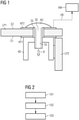
- figure 1 shows, in a schematic and exemplary manner, an arrangement according to the invention for checking a screw connection in an electrical device.
- the arrangement in figure 1 shown by way of example in a sectional view in the area of a through hole DL in a carrier plate LP1 or printed circuit board LP1, on which component groups for the electrical device (eg switched-mode power supply, single-stage or multi-stage power supply, etc.) are attached.
- the carrier plate LP1 has conductive contact surfaces KF1, KF2 (eg copper coating) both on a first side S1 and on a second side S2 in the area of the through hole DL.
- the through hole DL is listed as non-metallized. That is, there is no through-plating or electrically conductive connection between the contact surfaces KF1, KF2 on the first and the second side S1, S2 of the carrier plate LP1 through a metallic coating (eg copper, etc.).
- the arrangement has a conductive contact element KE for an electrically conductive connection to a further carrier plate LP2 of the electrical device.
- the contact element KE can be shaped according to a respective arrangement of the further carrier plate LP2.
- the further support plate LP2 can be arranged, for example, next to, above or at a 90° angle to the support plate LP1. If the further carrier plate LP2 - as in figure 1 shown as an example - attached at a 90° angle to the carrier plate LP1, the contact element KE can have a U-shaped profile or a bracket shape, for example.
- an electrically conductive connection e.g.
- Contact elements KE are pressed onto the contact surface KF1 on the first side S1 of the carrier plate LP1 by means of a screw connection.
- the connection of the contact element KE to the further carrier plate LP2 can, for example, be detachable (eg screw connection, plug connection, etc.) or non-detachable (eg by means of gluing, soldering, etc.).
- the contact element KE is made of an electrically conductive material - eg galvanized copper, etc. - executed.
- the arrangement has a screw element SE with a head part KO and a shaft part SC, which is also made of conductive material (e.g. galvanized copper, etc.).
- a thread is attached to the shank part SC of the screw element SE, through which the contact element KE can be fixed on the carrier plate LP1 or can be pressed against the contact surface KF1 on the first side S1 of the carrier plate LP1.
- the contact element KE has, for example, a threaded hole in a central bar.
- the screw element SE is attached in the non-metallized through hole DL of the carrier plate LP1 in such a way that the head part KO of the screw element SE is attached to the contact surface KF2 on the second Side S2 of the carrier plate LP1 is pressed.
- the screw element SE is inserted in an insertion direction R into the non-metallized through-hole DL.
- the screw element SE is attached, for example during the manufacture of the electrical device, in the non-metallized through-hole DL in such a way that the contact element KE is fixed to the carrier plate LP1 by the shank part SC of the screw element SE and is attached to the first side S1 of the carrier plate LP1 Contact surface KF1 is pressed. Furthermore, the head part KO of the screw element is pressed on the second side S2 of the carrier plate LP1 on the contact surface KF2 attached there. As a result, the screw element SE provides an electrically conductive connection between the contact element KE and the contact surface KF2 on the second side S2 of the carrier plate LP1.
- the head part KO of the screw element SE and the contact surface KF2 on the second side S2 of the carrier plate LP1 thus form a sensor or a sensor surface, with signals from the contact surface KF2 on the second side S2 of the carrier plate LP1 - e.g. in the form of voltage potentials, etc. - are accessible.
- the signals (e.g. voltage potential, etc.) that can be picked off on the second side S2 of the carrier plate LP1 can be determined, for example, via the functionality of the electrically conductive connection to the further carrier plate LP2 and thus via an assembly status of the screw element SE (e.g. missing screw element SE, insufficiently fixed or assembled Screw element, etc.) provide information.
- an evaluation device AW can be provided, for example, to which the signal can be forwarded via a connection VB.
- a switched-mode power supply or a power supply for example, an already existing controller unit (e.g. controller unit of a first stage in a multi-stage power supply) and/or a measuring unit, such as a device for measuring an input voltage of the electrical device or an output voltage of the electrical device, can be used as the evaluation device AW. be used.
- figure 2 shows an exemplary sequence of the method according to the invention for checking a screw connection in an electrical device with an in figure 1 arrangement shown as an example.
- the screw element SE is inserted in the insertion direction R into the non-metallized through-hole DL in the carrier plate LP1 in a production step 101 during the production of the electrical device (e.g. power supply, etc.).
- the contact element KE via which power and/or electrical signals are also transmitted in addition to establishing the mechanical connection between the carrier plate LP1 and the further carrier plate LP2, is pressed or pressed against the electrically conductive contact surface KF1 on the first side S1 of the carrier plate LP1. fixed.
- the screw element SE is attached in the non-metallized through hole DL in such a way that the head part KO of the screw element SE is pressed against the contact surface KF2 on the second side S2 of the carrier plate LP1 and the screw element SE thus creates a conductive connection between the contact surface KF2 the second side S2 of the carrier plate LP1 and the contact element KE produces.
- the head part KO of the screw element SE forms a sensor surface together with the contact surface KF2 on the second side S2 of the carrier plate LP1.
- a test step 102 which can be carried out, for example, during a test of the electrical device before delivery, during a trial operation of the electrical device, during commissioning and/or during operation of the electrical device, the sensor surface or the contact surface KF2 on the second side S2 of the carrier plate LP1 tapped a signal.
- the signal picked off can be a voltage potential, for example.
- an evaluation step 103 the signal picked off is evaluated, the signal reflecting the functionality of the electrically conductive connection between the carrier plate LP1 and the further carrier plate LP2, and an assembly state of the screw element or a proper execution of the screw connection can thus be derived from the signal. If, for example, no signal or no voltage potential is determined on the sensor surface or on the contact surface KF2 of the second side S2 of the carrier plate LP1, a missing screw element SE can be detected, for example. If, for example, a fluctuating, very small or too large signal is picked up at the sensor surface, it can the absence or a defective or faulty attachment or fixation of the screw element SE can also be determined. The faulty screw connection or an inadequately executed assembly of the screw element SE can thus be recognized and remedied very easily without the electrical device being damaged or safety risks arising.
- the picked-off signal can be forwarded to the evaluation unit AW via the connection VB, for example.
- the evaluation unit AW In the case of a switched-mode power supply or a power supply, for example, an existing control unit and/or measuring unit can be used as the evaluation device AW, from which, for example, an input voltage and/or output voltage of the electrical device or the power supply can be determined.
- the arrangement according to the invention and the associated method can be used to check respective screw connections in an electrical device, which are used not only for a mechanical connection but also for an electrically conductive connection between support plates LP1, LP2 in an electrical device.
- two screw connections are used in accordance with the arrangement according to the invention.
- an input voltage of the power supply is picked up as a signal from the sensor surface of the first screw connection and an output voltage of the power supply is picked up as a signal from the sensor surface of the second screw connection and evaluated.
- one of the two screw connections is faulty (e.g. missing screw element SE)
- no input voltage is measured by the measuring unit or the controller unit receives it when evaluating the signal pretends that the output voltage is too high. This way will ensures that the power supply does not start up.
- the faulty screw connection can thus be detected and corrected in test step 102 or in evaluation step 103, and accidental or unsafe contact between the contact element KE and the contact surface KF1 on the first side S1 of the carrier plate LP1 does not damage the electrical device.
Landscapes
- Engineering & Computer Science (AREA)
- General Engineering & Computer Science (AREA)
- Mechanical Engineering (AREA)
- Connections Arranged To Contact A Plurality Of Conductors (AREA)
Abstract
Die Erfindung betrifft ein Verfahren wie eine Anordnung zum Überprüfen von Schraubverbindungen in einem elektrischen Gerät, insbesondere in einer Stromversorgung bzw. einem Schaltnetzteil. Dabei wird durch zumindest eine Schraubverbindung mit Hilfe eines leitenden Kontaktelements (KE) im elektrischen Gerät eine elektrisch leitende Verbindung z.B. für Leistungs- und/oder Signalübertragung zwischen einer Trägerplatte (LP1) und einer weiteren Trägerplatte (LP2) des elektrischen Geräts hergestellt. Dabei wird ein Schraubelement (SE) in einem nicht metallisierten Durchgangsloch (DL) in der Trägerplatte (LP1) derart angebracht wird (101), dass das Kontaktelement (KE) für die elektrisch leitende Verbindung zwischen der Trägerplatte (LP1) mit der weiteren Trägerplatte (LP2) an eine Kontaktfläche (KF1) auf einer ersten Seite (S1) der Trägerplatte (LP2) angepresst wird und dass ein Kopfteil (KO) des Schraubelements (SE) an eine leitende Kontaktfläche (KF2) auf einer zweiten Seite (S2) der Trägerplatte (LP1) angepresst wird. Die leitenden Kontaktfläche (KF2) auf der zweiten Seite (S2) der Trägerplatte (LP2) und der Kopfteil (KO) des Schraubelements (SE) bilden dabei einen Sensor bzw. eine Sensorfläche, von welcher ein Signal abgegriffen wird (102). Das auf der Sensorfläche bzw. auf der Kontaktfläche (KF2) auf der zweiten Seite (S2) der Trägerplatte (LP2) abgegriffene Signal wird ausgewertet (103), wobei aus dem Signal ein Montagezustand des Schraubelements (SE) abgeleitet wird. Dadurch können auf einfach Weise fehlende oder nicht ordnungsgemäß montierte Schraubelemente (SE) erkannt werden.The invention relates to a method and an arrangement for checking screw connections in an electrical device, in particular in a power supply or a switched-mode power supply. An electrically conductive connection, e.g. for power and/or signal transmission, is established between a carrier plate (LP1) and another carrier plate (LP2) of the electrical device by means of at least one screw connection with the aid of a conductive contact element (KE). A screw element (SE) is attached (101) in a non-metallized through hole (DL) in the carrier plate (LP1) in such a way that the contact element (KE) for the electrically conductive connection between the carrier plate (LP1) and the other carrier plate ( LP2) is pressed against a contact surface (KF1) on a first side (S1) of the carrier plate (LP2) and that a head part (KO) of the screw element (SE) is pressed against a conductive contact surface (KF2) on a second side (S2) of the carrier plate (LP1) is pressed. The conductive contact surface (KF2) on the second side (S2) of the carrier plate (LP2) and the head part (KO) of the screw element (SE) form a sensor or a sensor surface from which a signal is picked up (102). The signal picked up on the sensor surface or on the contact surface (KF2) on the second side (S2) of the carrier plate (LP2) is evaluated (103), and an assembly state of the screw element (SE) is derived from the signal. As a result, missing or improperly installed screw elements (SE) can be easily detected.
Description
Die vorliegende Erfindung betrifft allgemein das Gebiet elektrischer und elektronischer Geräte, insbesondere den Bereich der Schaltnetzteile sowie der leistungselektronischen Schaltungen. Im Speziellen bezieht sich die vorliegende Erfindung auf ein Verfahren zum Überprüfen von Schraubverbindungen in einem elektrischen Gerät, insbesondere in einer Stromversorgung bzw. einem Schaltnetzteil. Dabei wird durch zumindest eine Schraubverbindung mit Hilfe eines leitenden Kontaktelements im elektrischen Gerät eine elektrisch leitende Verbindung z.B. für Leistungs- und/oder Signalübertragung zwischen einer Trägerplatte und einer weiteren Trägerplatte des elektrischen Geräts hergestellt. Weiterhin bezieht sich die vorliegende Erfindung auf eine Anordnung zur Durchführung des erfindungsgemäßen Verfahrens.The present invention generally relates to the field of electrical and electronic devices, in particular the field of switched-mode power supplies and power electronic circuits. In particular, the present invention relates to a method for checking screw connections in an electrical device, in particular in a power supply or a switched-mode power supply. An electrically conductive connection, e.g. for power and/or signal transmission, is established between a carrier plate and another carrier plate of the electrical device by means of at least one screw connection with the aid of a conductive contact element in the electrical device. Furthermore, the present invention relates to an arrangement for carrying out the method according to the invention.
Geräte, insbesondere elektrische oder elektronische Geräte wie z.B. Schaltnetzteile, leistungselektronische Schaltungen, Steuergeräte, etc. werden heutzutage üblicherweise aus elektrischen Bauelementen und/oder Bauelementgruppen aufgebaut. Die Bauelemente sind dabei auf einer Trägerplatte - einer so genannte Leiterplatte - anbracht. Die Träger- oder Leiterplatte dient einer mechanischen Befestigung sowie einer elektrischen Verbindung der Bauelemente. Üblicherweise bestehen Leiterplatten aus isolierendem Material mit daran haftenden leitenden Verbindungen und Kontaktflächen, welche z.B. einseitig oder auf beiden Seiten der Leiterplatte aufgebracht sein können.Devices, in particular electrical or electronic devices such as switched-mode power supplies, electronic power circuits, control devices, etc., are nowadays usually made up of electrical components and/or groups of components. The components are mounted on a carrier board - a so-called printed circuit board. The carrier board or printed circuit board is used for mechanical attachment and electrical connection of the components. Circuit boards usually consist of insulating material with conductive connections and contact surfaces adhering thereto, which can be applied, for example, to one side or to both sides of the circuit board.
Üblicherweise sind elektrische Gerät, wie z.B. Stromversorgungen bzw. Schaltnetzteil aus mehreren, mit elektrischen Bauelementen und/oder Bauelementgruppen bestückten Trägerplatten aufgebaut. In der Fertigung können die bestückten Trägerplatten z.B. vor einer Montage des elektrischen Geräts in einem Gehäuse oder Schaltschrank mittels Schraubelementen verbunden werden. Dabei kann auch vorgesehen sein, dass über eine mechanisch lösbare Verbindung, wie einer Schraubverbindung, einer Trägerplatte mit einer weiteren Trägerplatte eine Übertragung von elektrischem Strom bzw. eine Leistungsübertragung und/oder eine Signalübertragung stattfindet. Aus Sicherheitsgründe darf eine elektrisch leitende Verbindung zwischen Trägerplatten, welche durch eine Schraubverbindung mechanisch lösbar verbunden sind, nicht über ein Schraubelement, insbesondere nicht über ein an einem Schaft des Schraubelements angebrachtes Gewinde durchgeführt werden. Daher werden die Trägerplatten beispielsweise über Kontaktelemente elektrisch leitend verbunden.Electrical devices, such as power supplies or switched-mode power supplies, are usually made up of several carrier boards fitted with electrical components and/or groups of components. In production, the assembled carrier boards can be connected using screw elements, e.g. before the electrical device is installed in a housing or control cabinet. Provision can also be made for transmission of electrical current or power transmission and/or signal transmission to take place via a mechanically detachable connection, such as a screw connection, between a carrier plate and another carrier plate. For safety reasons, an electrically conductive connection between carrier plates, which are mechanically detachably connected by a screw connection, must not be made via a screw element, in particular not via a thread attached to a shank of the screw element. For this reason, the carrier plates are connected in an electrically conductive manner, for example via contact elements.
Dazu wird z.B. ein Kontaktelement mittels einer Schraubverbindung an eine an einer ersten Seite der Trägerplatte angebrachte, elektrisch leitende Kontaktfläche angepresst. Für die Schraubverbindungen werden meist in Trägerplatte vorhandene Durchkontaktierungen verbaut, wobei z.B. ein elektrisches Signal oder elektrischer Strom über die Durchkontaktierung zu einer leitenden Kontaktfläche auf der zweiten Seite der Trägerplatte geleitet werden kann. Für die elektrisch leitende Verbindung zu einer weiteren Trägerplatte kann das entsprechend ausgestaltete Kontaktelement mit einer leitenden Kontaktfläche oder mit Leiterbahnen der weiteren Trägerplatte lösbar oder nicht lösbar (z.B. mittels Ankleben, Löten, etc.) verbunden sein und so die elektrische Verbindung zu weiteren Geräteteile herstellen.For this purpose, for example, a contact element is pressed onto an electrically conductive contact surface attached to a first side of the carrier plate by means of a screw connection. For the screw connections, through-contacts are usually installed in the carrier plate, whereby, for example, an electrical signal or electric current can be routed via the through-contact to a conductive contact surface on the second side of the carrier plate. For the electrically conductive connection to a further carrier plate, the correspondingly designed contact element can be detachably or non-detachably connected to a conductive contact surface or to conductor tracks of the further carrier plate (e.g. by means of adhesive bonding, soldering, etc.) and thus establish the electrical connection to other device parts.
Während des Fertigungsprozesses - vor allem beim Verbinden der Geräteteile bzw. beim Zusammenfügen der bestückten Trägerplatten - kann es vorkommen, dass einzelne Schraubelemente zum Anpressen der Kontaktelemente vergessen, mangelhaft fixiert oder fehlerhaft angebracht werden. Trotz fehlender einzelner Schraubelemente oder mangelhafter Fixierung kann das Kontaktelement an der leitenden Kontaktfläche der Trägerplatte anliegen. Auf diese Weise kann z.B. ein unsicherer, elektrischer Kontakt zwischen den Trägerplatten entstehen. Aufgrund der Nutzung von Durchkontaktierungen für die jeweiligen Schraubverbindungen werden Strom und/oder Signale trotz des unsicheren, elektrischen Kontakts bzw. eines nicht ordnungsgemäß montierten Schraubelements weiterhin von ersten auf die zweite Seite der Trägerplatte übertragen. Allerdings können Funktion und Sicherheit des elektrischen Geräts beeinträchtigt sein. Da insbesondere bei elektrischen Geräten, wie z.B. bei Schaltnetzteilen, auch größere Ströme zwischen Trägerplatten übertragen werden, kann ein unsicherer, elektrischer Kontakt beispielsweise zu verstärkter Wärmeentwicklung und/oder Funkenbildung und damit zu Schäden an den auf einer der Trägerplatten bestückten Bauelementgruppen bis zum Abbrand einzelner Bauelementgruppe führen.During the manufacturing process - especially when connecting the device parts or when assembling the assembled carrier plates - it can happen that individual screw elements for pressing the contact elements are forgotten or not fixed properly or installed incorrectly. Despite the lack of individual screw elements or inadequate fixation, the contact element can rest against the conductive contact surface of the carrier plate. In this way, for example, an unsafe electrical contact can arise between the carrier plates. Due to the use of vias for the respective screw connections, current and/or signals continue to be transmitted from the first to the second side of the carrier plate, despite the uncertain electrical contact or an incorrectly installed screw element. However, the function and safety of the electrical device can be impaired. Since larger currents are also transmitted between carrier plates, particularly in the case of electrical devices, such as switched-mode power supplies, an unsafe electrical contact can, for example, lead to increased heat generation and/or sparking and thus to damage to the component groups fitted on one of the carrier plates, up to and including individual component groups burning up to lead.
Üblicherweise werden während des Fertigungsprozesses von elektrischen Geräten die Schraubverbindungen, durch welche mittels eines Kontaktelements neben mechanisch lösbaren Verbindungen auch elektrisch leitende Verbindungen zwischen bestückten Träger- bzw. Leiterplatten hergestellt werden, manuell - beispielsweise nach dem so genannten Vier-Augen-Prinzip - überprüft. Das Vier-Augen-Prinzip erfordert allerdings mehr Personal und Zeit und ist meist mit höheren Kosten verbunden, da üblicherweise eine zusätzliche, mit Kontrollaufgaben betraute Arbeitskraft vorhanden sein muss.Normally, during the manufacturing process of electrical devices, the screw connections, through which electrically conductive connections are made between assembled carrier boards or printed circuit boards by means of a contact element in addition to mechanically detachable connections, are checked manually - for example according to the so-called four-eyes principle. However, the four-eyes principle requires more staff and time and is usually associated with higher costs, since an additional worker entrusted with control tasks usually has to be available.
Alternativ kann eine Überprüfung der Schraubverbindungen auch mittels automatischer, optischer Inspektion (oder englisch automated optical inspection, kurz AOI) erfolgen. Dabei werden z.B. mittels eines Bildverarbeitungsverfahren Fehler in der Produktion oder Fertigung gefunden und gemeldet. AOI-System werden z.B. in der Leiterplattenentwicklung zur Bestück- und Lötstellenkontrolle eingesetzt. Eine Kontrolle der Schraubverbindung mittels AOI weist aber den Nachteil auf, dass dazu ein weiterer Prozessschritt in der Fertigung vorsehen werden muss und dass eine Erfassung von z.B. in einem Winkel von 90° verbundenen Trägerplatten mittels Bildverarbeitungsverfahren meist aufwendig ist. Weiterhin können mittels AOI zwar fehlende Schraubelemente erkannt werden, aber eine mangelhafte oder fehlerhafte Fixierung von Schraubelementen ist meist nur schwer erkennbar bzw. feststellbar.Alternatively, the screw connections can also be checked by means of an automated optical inspection (or AOI for short). Errors in production or manufacturing are found and reported using an image processing method, for example. AOI systems are used, for example, in printed circuit board development to check placement and soldering points. However, checking the screw connection using AOI has the disadvantage that that an additional process step has to be provided for in production and that detecting carrier plates connected at an angle of 90°, for example, using image processing methods is usually complex. Furthermore, although missing screw elements can be detected by means of AOI, it is usually difficult to recognize or determine an inadequate or faulty fixation of screw elements.
Der Erfindung liegt daher die Aufgabe zugrunde, ein Verfahren zum Überprüfen einer Schraubverbindung für einen mechanische und elektrisch leitende Verbindung einer Trägerplatte mit einer weiteren Trägerplatte in einem elektrischen Gerät sowie eine zugehörige Anordnung anzugeben, welche während einer Fertigung und/oder Inbetriebnahme des elektrischen Geräts auf einfache Weise für Überprüfungszwecke zeit- und/oder kosteneffizient eingesetzt werden können.The invention is therefore based on the object of specifying a method for checking a screw connection for a mechanical and electrically conductive connection of a carrier plate to another carrier plate in an electrical device, as well as an associated arrangement, which can be easily Way for verification purposes can be used time and / or cost efficient.
Diese Aufgabe wird durch ein Verfahren und eine zugehörige Anordnung der eingangs beschriebenen Art mit den Merkmalen der unabhängigen Ansprüche gelöst. Vorteilhafte Ausführungsformen der vorliegenden Erfindung sind in den abhängigen Ansprüchen beschrieben.This object is achieved by a method and an associated arrangement of the type described in the introduction with the features of the independent claims. Advantageous embodiments of the present invention are described in the dependent claims.
Erfindungsgemäß erfolgt die Lösung der Aufgabe durch ein Verfahren der eingangs beschriebenen Art für eine Überprüfung von Schraubverbindungen in einem elektrischen Geräts insbesondere eines Schaltnetzteils oder einer leistungselektronischen Schaltung, wobei durch die jeweilige Schraubverbindung mittels eines elektrisch leitenden Kontaktelements neben einer mechanisch lösbaren Verbindung auch ein elektrisch leitende Verbindung zur Leistungs-, Strom- und/oder Signalübertragung zwischen einer Trägerplatte des elektrischen Geräts und einer weiteren Trägerplatte des elektrischen Geräts hergestellt wird. Dabei wird für die jeweilige Schraubverbindung ein Schraubelement derart in einem nicht metallisierten Durchgangsloch in der Trägerplatte derart angebracht, dass das Kontaktelement für die elektrisch leitende Verbindung zwischen der Trägerplatte mit der weiteren Trägerplatte an eine Kontaktfläche auf einer ersten Seite der Trägerplatte angepresst wird und dass ein Kopfteil des Schraubelements an eine leitende Kontaktfläche auf einer zweiten Seite der Trägerplatte angepresst wird. An der leitenden Kontaktfläche auf der zweiten Seite der Trägerplatte wird dann ein Signal abgegriffen. Das abgegriffene Signal wird ausgewertet, wobei aus dem Signal ein Montagezustand des Schraubelements abgeleitet werden kann.According to the invention, the object is achieved by a method of the type described above for checking screw connections in an electrical device, in particular a switched-mode power supply or a power electronic circuit, with the respective screw connection using an electrically conductive contact element not only a mechanically detachable connection but also an electrically conductive connection is produced for power, current and / or signal transmission between a carrier plate of the electrical device and another carrier plate of the electrical device. In this case, for the respective screw connection, a screw element is fitted in a non-metallized through-hole in the support plate in such a way that the contact element for the electrically conductive connection between the carrier plate and the further carrier plate is pressed against a contact surface on a first side of the carrier plate and that a head part of the screw element is pressed against a conductive contact surface on a second side of the carrier plate. A signal is then picked up at the conductive contact surface on the second side of the carrier plate. The signal picked up is evaluated, and an assembly state of the screw element can be derived from the signal.
Der Hauptaspekt des erfindungsgemäßen Verfahrens besteht darin, dass durch die Anbringung des Schraubelements in einem nicht metallisierten Durchgangsloch eine Signalübertragung vom Kontaktelement, welches an der ersten Seite der Trägerplatte fixiert ist, zur leitenden Kontaktfläche auf der zweiten Seite der Trägerplatte hergestellt wird. Dabei können der Kopfteil des Schraubelements und die leitende Kontaktfläche auf der zweiten Seite der Trägerplatte als Sensor bzw. Sensorfläche verwendet werden, welche ein Signal zur Verfügung stellt. Aus diesem Signal kann z.B. eine Funktionsfähigkeit der elektrisch leitenden Verbindung zur weiteren Trägerplatte und damit über den jeweiligen Montagezustand des Schraubelements abgeleitet werden. Ist beispielsweise kein Schraubelement angebracht, so kann kein Signal an der Kontaktfläche auf der zweiten Seite der Trägerplatte abgegriffen. Auch mangelhaft fixierte Schraubelemente sind anhand des Signals auf einfache und kostensparende Weise erkennbar. Durch das erfindungsgemäße Verfahrens sind damit Montagefehler bei Schraubverbindungen, welche auch zur elektrisch leitenden Verbindung dienen, sehr einfach, kostensparend und rasch entdeckbar und behebbar. Schädigungen des elektrischen Geräts und Sicherheitsrisken können damit auf einfache Weise verhindert werden.The main aspect of the method according to the invention is that by attaching the screw element in a non-metallized through hole, a signal is transmitted from the contact element, which is fixed to the first side of the carrier plate, to the conductive contact surface on the second side of the carrier plate. The head part of the screw element and the conductive contact surface on the second side of the carrier plate can be used as a sensor or sensor surface, which makes a signal available. This signal can be used, for example, to derive the functionality of the electrically conductive connection to the additional carrier plate and thus the respective assembly status of the screw element. For example, if no screw element is attached, then no signal can be picked up at the contact surface on the second side of the carrier plate. Poorly fixed screw elements can also be identified in a simple and cost-saving manner using the signal. As a result of the method according to the invention, assembly errors in screw connections, which are also used for the electrically conductive connection, can be discovered and remedied very simply, cost-effectively and quickly. Damage to the electrical device and safety risks can thus be prevented in a simple manner.
Weiterhin ist es von Vorteil, wenn das an der leitenden Kontaktfläche auf der zweiten Seite der Trägerplatte abgegriffene Signal an eine Auswerteeinrichtung weitergeleitet wird.Furthermore, it is advantageous if the signal picked up at the conductive contact surface on the second side of the carrier plate is forwarded to an evaluation device.
Durch die Auswerteeinrichtung kann das Signal entsprechend ausgewertet werden und bei einer nicht ordnungsgemäßen Anbringung des Schraubelements z.B. eine Fehlermeldung ausgegeben werden.The signal can be evaluated accordingly by the evaluation device and, for example, an error message can be output if the screw element is not properly attached.
Idealerweise wird als Auswerteeinrichtung eine Reglereinheit und/oder eine Messeinheit (z.B. Eingangsspannungsmessung, Ausgangsspannungsmessung, etc.) verwendet, welche bereits im elektrischen Gerät vorhanden sind. Auf diese Weise können bereits im Gerät vorhandene Einheit genutzt und zusätzliche Kosten gespart werden.Ideally, a control unit and/or a measuring unit (e.g. input voltage measurement, output voltage measurement, etc.) that are already present in the electrical device is used as the evaluation device. In this way, units already present in the device can be used and additional costs can be saved.
Weiterhin ist es günstig, wenn als Signal an der leitenden Kontaktfläche auf der zweiten Seite der Trägerplatte ein Spannungspotential abgegriffen wird. Ein derartige Signal kann beispielsweise ohne zusätzlichen Aufwand von im elektrischen Gerät vorhandenen Einheiten (z.B. Regler, Messeinheit, etc.) detektiert und ausgewertet werden.Furthermore, it is favorable if a voltage potential is tapped off as a signal at the conductive contact area on the second side of the carrier plate. Such a signal can, for example, be detected and evaluated by units present in the electrical device (e.g. controller, measuring unit, etc.) without any additional effort.
Zweckmäßigerweise wird das Signal während eines Probebetriebs und/oder bei einer Inbetriebnahme des elektrischen Geräts erfasst und ausgewertet. Damit wird auf einfache Weise verhindert, dass ein nicht ordnungsgemäß montiertes Gerät ausgeliefert oder in Betrieb genommen wird. Weiterhin kann z.B. zu Wartungszwecken das Signal auch während eines laufenden Betriebs des elektrischen Geräts abgegriffen und ausgewertet werden.The signal is expediently recorded and evaluated during trial operation and/or when the electrical device is put into operation. This is a simple way of preventing an improperly installed device from being delivered or put into operation. Furthermore, for maintenance purposes, for example, the signal can also be picked up and evaluated while the electrical device is in operation.
Die Lösung der Aufgabe erfolgt weiterhin durch eine Anordnung zum Überprüfen zumindest einer Schraubverbindung eines auf Trägerplatten angeordneten, elektrischen Geräts, insbesondere einer Stromversorgung bzw. eines Schaltnetzteils. Dabei weist die Anordnung zumindest auf:
- eine Trägerplatte, welche zumindest ein nicht metallisiertes Durchgangsloch und zumindest im Bereich des Durchgangslochs auf einer ersten Seite und auf einer zweite Seite leitende Kontaktflächen aufweist;
- ein leitendes Kontaktelement, welches neben einer mechanischen Verbindung eine elektrisch leitende Verbindung zwischen der Trägerplatte und einer weiteren Trägerplatte herstellt;
- ein Schraubelement, welches derart im nicht metallisierten Durchgangsloch angeordnet ist, dass das Kontaktelement für die elektrisch leitende Verbindung zur weiteren Trägerplatte an eine Kontaktfläche auf einer ersten Seite der Trägerplatte angepresst wird und dass ein Kopfteil des Schraubelements an eine leitende Kontaktfläche auf einer zweiten Seite der Trägerplatte angepresst wird, wobei von der leitenden Kontaktfläche auf der zweiten Seite der Trägerplatte ein Signal abgreifbar ist, aus welchem ein Montagezustand des Schraubelements abgeleitet werden kann.
- a carrier plate which has at least one non-metallized through hole and at least in the area of the through hole on a first side and on a second side conductive contact areas;
- a conductive contact element which, in addition to a mechanical connection, produces an electrically conductive connection between the carrier plate and another carrier plate;
- a screw element which is arranged in the non-metallized through-hole in such a way that the contact element for the electrically conductive connection to the further carrier plate is pressed against a contact surface on a first side of the carrier plate and that a head part of the screw element is pressed against a conductive contact surface on a second side of the carrier plate is pressed, wherein a signal can be tapped from the conductive contact surface on the second side of the carrier plate, from which a mounting state of the screw element can be derived.
Durch die Anordnung kann auf einfache, rasche Weise und kosteneffizient eine mangelhafte Montage eines Schraubelements bei einer Schraubverbindung erkannt werden, welche in einem elektrischen Gerät neben einer mechanischen Verbindung auch zur elektrisch leitenden Verbindung zwischen Trägerplatten des Geräts dient. Weiterhin wird durch die Anordnung sichergestellt, dass das elektrische Gerät bei einem fehlenden Schraubelement trotz eines zufälligen Kontakts zwischen dem Kontaktelement und der leitenden Kontaktfläche auf der ersten Seite der Trägerplatte nicht hochfährt. Auf diese Weise werden z.B. fehlende Schraubelemente rasch entdeckt und Schäden am Gerät verhindert.The arrangement can be used in a simple, quick and cost-efficient manner to detect defective assembly of a screw element in a screw connection which, in addition to a mechanical connection, also serves as an electrically conductive connection between the support plates of the device in an electrical device. Furthermore, the arrangement ensures that the electrical device does not start up if a screw element is missing, despite accidental contact between the contact element and the conductive contact surface on the first side of the carrier plate. In this way, for example, missing screw elements are quickly discovered and damage to the device is prevented.
Weiterhin ist es günstig, wenn eine Auswerteeinheit zum Auswerten des an der leitenden Kontaktfläche auf der zweiten Seite der Trägerplatte abgegriffenen Signals vorgesehen ist, um mangelhaft ausgeführte Schraubverbindungen (z.B. fehlendes Schraubelement, nicht richtig fixiertes Schraubelement, etc.) rasch zu detektieren und zu erkennen. Als Auswerteeinheit können beispielsweise im elektrischen Gerät bereits vorhandene Reglereinheiten, Messeinheiten, etc. genutzt werden, um z.B. zusätzliche Kosten zu sparen.Furthermore, it is favorable if an evaluation unit is provided for evaluating the signal picked up at the conductive contact surface on the second side of the carrier plate, in order to quickly detect and recognize poorly executed screw connections (e.g. missing screw element, screw element not fixed correctly, etc.). For example, controller units, measuring units, etc. that are already present in the electrical device can be used as an evaluation unit in order to save additional costs, for example.
Es ist weiterhin von Vorteil, wenn das Kontaktelement und das Schraubelement aus leitendem Material (z.B. verzinktem Kupfer, etc.) hergestellt sind. Auf diese Weise wird eine Signalübertragung zwischen der weiteren Trägerplatte und der Kontaktfläche auf der ersten Seite der Trägerplatte über das Kontaktelement und zwischen dem Kontaktelement und der Kontaktfläche auf der zweiten Seite der Trägerplatte über das Schraubelement sichergestellt. Anhand des Signals kann dann einerseits die Funktionsfähigkeit der elektrisch leitenden Verbindung zwischen der Trägerplatte und der weiteren Trägerplatte sowie die korrekte Montage des Schraubelements festgestellt werden.It is also advantageous if the contact element and the screw element are made of conductive material (e.g. galvanized copper, etc.). In this way, signal transmission between the further carrier plate and the contact surface on the first side of the carrier plate via the contact element and between the contact element and the contact surface on the second side of the carrier plate via the screw element is ensured. On the one hand, the functionality of the electrically conductive connection between the carrier plate and the further carrier plate and the correct assembly of the screw element can then be determined on the basis of the signal.
Weiterhin ist es günstig, wenn das Kontaktelement ein U-förmiges Profil oder eine Bügelform aufweist. Durch ein u-förmig bzw. bügelförmig ausgeführtes Kontaktelement können beispielsweise übereinander oder in einem 90°-Winkel zueinander angeordneten Trägerplatten sehr einfach mechanisch und elektrisch leitend verbunden werden. Dazu kann z.B. ein Schenkel des u-förmig bzw. bügelförmig ausgeführten Kontaktelements mit auf jener weiteren Trägerplatte lösbar oder nicht lösbar angebracht werden, mit welcher die Trägerplatte verbunden werden soll. Durch eine Bohrung in einem Mittelsteg des u-förmig bzw. bügelförmig ausgeführten Kontaktelements kann dann sehr einfach die Schraubverbindung hergestellt werden.Furthermore, it is favorable if the contact element has a U-shaped profile or a bracket shape. By means of a U-shaped or bow-shaped contact element, for example, support plates arranged one above the other or at a 90° angle to one another can be mechanically and electrically conductively connected very easily. For this purpose, for example, one leg of the U-shaped or bow-shaped contact element can be attached detachably or non-detachably to that further carrier plate to which the carrier plate is to be connected. The screw connection can then be produced very easily through a bore in a central web of the U-shaped or bow-shaped contact element.
Die Erfindung wird nachfolgend in beispielhafter Weise anhand der beigefügten Figuren erläutert. Dabei zeigen:
- Figur 1
- beispielhaft und schematisch eine erfindungsgemäße Anordnung zum Überprüfen einer Schraubverbindung in einer Schnittansicht im Bereich eines Durchgangslochs in der Trägerplatte
- Figur 2
- schematisch einen beispielshaften Ablauf des erfindungsgemäßen Verfahrens zum Überprüfen einer Schraubverbindung in einem elektrischen Gerät
- figure 1
- an exemplary and schematic arrangement according to the invention for checking a screw connection in a sectional view in the area of a through hole in the support plate
- figure 2
- schematically shows an exemplary sequence of the method according to the invention for checking a screw connection in an electrical device
Für eine elektrisch leitende Verbindung zu einer weiteren Trägerplatte LP2 des elektrischen Geräts weist die Anordnung ein leitendes Kontaktelement KE auf. Das Kontaktelement KE kann entsprechend einer jeweiligen Anordnung der weiteren Trägerplatte LP2 ausgeformt sein. Die weitere Trägerplatte LP2 kann je nach Gehäuse oder Montage des elektrischen Geräts z.B. neben, über oder in einem 90°-Winkel zur Trägerplatte LP1 angeordnet sein. Wird die weitere Trägerplatte LP2 - wie in
Für die Schraubverbindung des Kontaktelements KE mit der Trägerplatte LP1 weist die Anordnung ein Schraubelement SE mit einem Kopfteil KO und einem Schaftteil SC auf, welches ebenfalls aus leitendem Material (z.B. verzinktes Kupfer, etc.) hergestellt ist. Am Schaftteil SC des Schraubelements SE ist ein Gewinde angebracht, durch welches das Kontaktelement KE an der Trägerplatte LP1 fixierbar bzw. an die Kontaktfläche KF1 auf der ersten Seite S1 der Trägerplatte LP1 anpressbar ist. Das Kontaktelement KE weist dazu z.B. in einem Mittelsteg eine Bohrung mit Gewinde auf.For the screw connection of the contact element KE to the carrier plate LP1, the arrangement has a screw element SE with a head part KO and a shaft part SC, which is also made of conductive material (e.g. galvanized copper, etc.). A thread is attached to the shank part SC of the screw element SE, through which the contact element KE can be fixed on the carrier plate LP1 or can be pressed against the contact surface KF1 on the first side S1 of the carrier plate LP1. For this purpose, the contact element KE has, for example, a threaded hole in a central bar.
Zum Fixieren bzw. zum Anpressen des Kontaktelements KE an die Kontaktfläche KF1 auf der ersten Seite S1 der Trägerplatte LP1 ist das Schraubelement SE im nicht metallisierten Durchgangsloch DL der Trägerplatte LP1 derart angebracht, dass der Kopfteil KO des Schraubelements SE an die Kontaktfläche KF2 auf der zweiten Seite S2 der Trägerplatte LP1 angepresst wird. Dazu wird das Schraubelement SE in einer Einfügerichtung R in das nicht metallisierte Durchgangsloch DL eingefügt. Das bedeutet, das Schraubelement SE wird z.B. während der Fertigung des elektrischen Geräts derart im nicht metallisierte Durchgangsloch DL angebracht, dass das Kontaktelement KE durch den Schaftteil SC des Schraubelements SE an der Trägerplatte LP1 fixiert und an die auf der ersten Seite S1 der Trägerplatte LP1 aufgebrachte Kontaktfläche KF1 angepresst wird. Weiterhin ist der Kopfteil KO des Schraubelements auf der zweiten Seite S2 der Trägerplatte LP1 an der dort angebrachten Kontaktfläche KF2 angepresst. Das Schraubelement SE stellt dadurch eine elektrisch leitende Verbindung zwischen dem Kontaktelement KE und der Kontaktfläche KF2 auf der zweiten Seite S2 der Trägerplatte LP1 her.To fix or to press the contact element KE against the contact surface KF1 on the first side S1 of the carrier plate LP1, the screw element SE is attached in the non-metallized through hole DL of the carrier plate LP1 in such a way that the head part KO of the screw element SE is attached to the contact surface KF2 on the second Side S2 of the carrier plate LP1 is pressed. For this purpose, the screw element SE is inserted in an insertion direction R into the non-metallized through-hole DL. This means that the screw element SE is attached, for example during the manufacture of the electrical device, in the non-metallized through-hole DL in such a way that the contact element KE is fixed to the carrier plate LP1 by the shank part SC of the screw element SE and is attached to the first side S1 of the carrier plate LP1 Contact surface KF1 is pressed. Furthermore, the head part KO of the screw element is pressed on the second side S2 of the carrier plate LP1 on the contact surface KF2 attached there. As a result, the screw element SE provides an electrically conductive connection between the contact element KE and the contact surface KF2 on the second side S2 of the carrier plate LP1.
Der Kopfteil KO des Schraubelements SE und die Kontaktfläche KF2 auf der zweiten Seite S2 der Trägerplatte LP1 bilden dadurch einen Sensor bzw. eine Sensorfläche, wobei von Kontaktfläche KF2 auf der zweiten Seite S2 der Trägerplatte LP1 Signale - z.B. in Form von Spannungspotentialen, etc. - abgreifbar sind. Die auf der zweiten Seite S2 der Trägerplatte LP1 abgreifbaren Signale (z.B. Spannungspotential, etc.) können beispielsweise über eine Funktionsfähigkeit der elektrisch leitenden Verbindung zur weiteren Trägerplatte LP2 und damit über einen Montagezustand des Schraubelements SE (z.B. fehlendes Schraubelement SE, mangelhaft fixiertes bzw. montiertes Schraubelement, etc.) Aufschluss geben.The head part KO of the screw element SE and the contact surface KF2 on the second side S2 of the carrier plate LP1 thus form a sensor or a sensor surface, with signals from the contact surface KF2 on the second side S2 of the carrier plate LP1 - e.g. in the form of voltage potentials, etc. - are accessible. The signals (e.g. voltage potential, etc.) that can be picked off on the second side S2 of the carrier plate LP1 can be determined, for example, via the functionality of the electrically conductive connection to the further carrier plate LP2 and thus via an assembly status of the screw element SE (e.g. missing screw element SE, insufficiently fixed or assembled Screw element, etc.) provide information.
Für eine entsprechende Auswertung des abgegriffenen Signals kann beispielsweise eine Auswerteeinrichtung AW vorgesehen sein, an welche das Signal über einen Verbindung VB weitergeleitbar ist. Als Auswerteeinrichtung AW können z.B. bei einem Schaltnetzteil oder einer Stromversorgung eine bereits vorhandene Reglereinheit (z.B. Reglereinheit einer ersten Stufe bei einer mehrstufigen Stromversorgung) und/oder eine Messeinheit, wie z.B. eine Einrichtung zu Messung einer Eingangsspannung des elektrischen Geräts oder einer Ausgangsspannung des elektrischen Geräts, verwendet werden.For a corresponding evaluation of the tapped signal, an evaluation device AW can be provided, for example, to which the signal can be forwarded via a connection VB. In the case of a switched-mode power supply or a power supply, for example, an already existing controller unit (e.g. controller unit of a first stage in a multi-stage power supply) and/or a measuring unit, such as a device for measuring an input voltage of the electrical device or an output voltage of the electrical device, can be used as the evaluation device AW. be used.
Für die Durchführung des erfindungsgemäßen Verfahrens bzw. zum Überprüfen der Schraubverbindung wird während der Fertigung des elektrischen Geräts (z.B. Stromversorgung, etc.) in einem Fertigungsschritt 101 das Schraubelement SE in das nicht metallisiertes Durchgangsloch DL in der Trägerplatte LP1 in der Einfügerichtung R eingefügt. Über das Schraubelement SE wird einerseits das Kontaktelement KE, über welches zusätzlich zur Herstellung der mechanischen Verbindung der Trägerplatte LP1 mit der weiteren Trägerplatte LP2 auch Leistung und/oder elektrische Signale übertragen werden, an die elektrisch leitende Kontaktfläche KF1 an der ersten Seite S1 der Trägerplatte LP1 angepresst bzw. fixiert. Andererseits wird im Fertigungsschritt 101 das Schraubelement SE im nicht metallisierten Durchgangsloch DL derart angebracht, dass der Kopfteil KO des Schraubelements SE an die Kontaktfläche KF2 auf der zweiten Seite S2 der Trägerplatte LP1 anpresst wird und das Schraubelement SE damit eine leitende Verbindung zwischen der Kontaktfläche KF2 auf der zweiten Seite S2 der Trägerplatte LP1 und dem Kontaktelement KE herstellt. Der Kopfteil KO des Schraubelements SE bildet gemeinsam mit der Kontaktfläche KF2 auf der zweiten Seite S2 der Trägerplatte LP1 eine Sensorfläche.To carry out the method according to the invention or to check the screw connection, the screw element SE is inserted in the insertion direction R into the non-metallized through-hole DL in the carrier plate LP1 in a
In einem Prüfschritt 102, welcher z.B. bei einer Prüfung des elektrischen Geräts vor Auslieferung, bei einem Probebetrieb des elektrischen Geräts, bei einer Inbetriebnahme und/oder im Betrieb des elektrischen Geräts durchgeführt werden kann, wird von der Sensorfläche bzw. von der Kontaktfläche KF2 auf der zweiten Seite S2 der Trägerplatte LP1 ein Signal abgegriffen. Das abgegriffene Signal kann beispielsweise ein Spannungspotential sein.In a
In einem Auswerteschritt 103 wird das abgegriffene Signal ausgewertet, wobei durch das Signal eine Funktionsfähigkeit der elektrisch leitenden Verbindung zwischen der Trägerplatte LP1 und der weiteren Trägerplatte LP2 wiedergibt und dadurch aus dem Signal ein Montagezustand des Schraubelements bzw. einen ordnungsgemäße Ausführung der Schraubverbindung abgeleitet werden kann. Wird beispielsweise an der Sensorfläche bzw. an der Kontaktfläche KF2 der zweiten Seite S2 der Trägerplatte LP1 kein Signal bzw. kein Spannungspotential ermittelt, so kann z.B. ein Fehlen des Schraubelements SE erkannt werden. Wird z.B. ein schwankendes, sehr kleines oder zu großes Signal an der Sensorfläche abgegriffen, so kann daraus ebenfalls das Fehlen oder eine mangelhafte bzw. fehlerhafte Anbringung oder Fixierung des Schraubelements SE festgestellt werden. Die fehlerhafte Schraubverbindung bzw. eine mangelhaft ausgeführte Montage des Schraubelements SE kann damit sehr einfach erkannt und behoben werden, ohne dass das elektrische Gerät beschädigt wird oder es zu Sicherheitsrisken kommt.In an
Für die Auswertung kann das abgegriffene Signal beispielsweise über die Verbindung VB an die Auswerteeinheit AW weitergeleitet werden. Als Auswerteeinrichtung AW kann z.B. bei einem Schaltnetzteil oder einer Stromversorgung eine bereits vorhandene Reglereinheit und/oder Messeinheit genutzt werden, von welchen z.B. eine Eingangsspannung und/oder Ausgangsspannung des elektrischen Geräts bzw. der Stromversorgung ermittelt werden.For the evaluation, the picked-off signal can be forwarded to the evaluation unit AW via the connection VB, for example. In the case of a switched-mode power supply or a power supply, for example, an existing control unit and/or measuring unit can be used as the evaluation device AW, from which, for example, an input voltage and/or output voltage of the electrical device or the power supply can be determined.
Die erfindungsgemäße Anordnung und das zugehörige Verfahren können zur Überprüfung von jeweiligen Schraubverbindungen in einem elektrischen Gerät genutzt werden, welche nicht nur für eine mechanische Verbindung, sondern auch für eine elektrisch leitende Verbindung zwischen Trägerplatten LP1, LP2 in einem elektrischen Gerät eingesetzt werden.The arrangement according to the invention and the associated method can be used to check respective screw connections in an electrical device, which are used not only for a mechanical connection but also for an electrically conductive connection between support plates LP1, LP2 in an electrical device.
Bei einer speziellen Anwendungsvariante in einer elektrischen Stromversorgung werden z.B. zwei Schraubverbindungen entsprechend der erfindungsgemäßen Anordnung verwendet. Dabei wird beispielsweise von der Sensorfläche der ersten Schraubverbindung als Signal eine Eingangsspannung der Stromversorgung und von der Sensorfläche der zweiten Schraubverbindung als Signal eine Ausgangsspannung der Stromversorgung abgegriffen und ausgewertet. Ist beispielsweise eine der beiden Schraubverbindungen fehlerhaft (z.B. fehlendes Schraubelement SE), so wird je nach fehlendem oder mangelhaft montiertem Schraubelemente SE z.B. im Prüfschritt 102 bzw. im Auswerteschritt 103 z.B. von der Messeinheit keine Eingangsspannung gemessen bzw. es wird der Reglereinheit bei der Auswertung des Signals eine zu hohe Ausgangsspannung vorgetäuscht. Auf diese Weise wird sichergestellt, dass die Stromversorgung nicht hochfährt. Die fehlerhafte Schraubverbindung kann damit im Prüfschritt 102 bzw. im Auswerteschritt 103 erkannt und behoben werden und ein zufälliger bzw. unsicherer Kontakt zwischen dem Kontaktelement KE und der Kontaktfläche KF1 auf der ersten Seite S1 der Trägerplatte LP1 führt zu keiner Schädigung des elektrischen Geräts.In a special application variant in an electrical power supply, for example, two screw connections are used in accordance with the arrangement according to the invention. In this case, for example, an input voltage of the power supply is picked up as a signal from the sensor surface of the first screw connection and an output voltage of the power supply is picked up as a signal from the sensor surface of the second screw connection and evaluated. If, for example, one of the two screw connections is faulty (e.g. missing screw element SE), then, depending on whether the screw element SE is missing or installed incorrectly, e.g. in
Claims (9)
Priority Applications (2)
| Application Number | Priority Date | Filing Date | Title |
|---|---|---|---|
| EP20191535.2A EP3957869A1 (en) | 2020-08-18 | 2020-08-18 | Method and assembly for testing screw connections |
| PCT/EP2021/071655 WO2022037936A1 (en) | 2020-08-18 | 2021-08-03 | Method and arrangement for inspecting screw connections |
Applications Claiming Priority (1)
| Application Number | Priority Date | Filing Date | Title |
|---|---|---|---|
| EP20191535.2A EP3957869A1 (en) | 2020-08-18 | 2020-08-18 | Method and assembly for testing screw connections |
Publications (1)
| Publication Number | Publication Date |
|---|---|
| EP3957869A1 true EP3957869A1 (en) | 2022-02-23 |
Family
ID=72147898
Family Applications (1)
| Application Number | Title | Priority Date | Filing Date |
|---|---|---|---|
| EP20191535.2A Withdrawn EP3957869A1 (en) | 2020-08-18 | 2020-08-18 | Method and assembly for testing screw connections |
Country Status (2)
| Country | Link |
|---|---|
| EP (1) | EP3957869A1 (en) |
| WO (1) | WO2022037936A1 (en) |
Family Cites Families (5)
| Publication number | Priority date | Publication date | Assignee | Title |
|---|---|---|---|---|
| US3459447A (en) * | 1966-12-13 | 1969-08-05 | Huck Mfg Co | Flush fastener for panel assembly including soft core material |
| GB2241466A (en) * | 1989-12-12 | 1991-09-04 | F P Fire Protection Services L | Fire resistant materials |
| FR2676244B1 (en) * | 1991-05-07 | 1994-01-28 | Francis Ovaert | COMPOSITE STRUCTURE, ESPECIALLY FOR THE BUILDING. |
| JP3553141B2 (en) | 1994-07-28 | 2004-08-11 | ソニー株式会社 | Transportation screw detector |
| DE102007010091A1 (en) * | 2007-03-02 | 2008-09-04 | Daimler Ag | Connection method for vehicles, involves providing paint-corrosive element for mechanical attachment and electrical mass contacting of retained attachment part between paint-corrosive element and body part |
-
2020
- 2020-08-18 EP EP20191535.2A patent/EP3957869A1/en not_active Withdrawn
-
2021
- 2021-08-03 WO PCT/EP2021/071655 patent/WO2022037936A1/en active Application Filing
Also Published As
| Publication number | Publication date |
|---|---|
| WO2022037936A1 (en) | 2022-02-24 |
Similar Documents
| Publication | Publication Date | Title |
|---|---|---|
| DE102007020882B4 (en) | Device for checking the attachment of a printed circuit board to a carrier | |
| DE102014200188A1 (en) | Wiring harness for electrically conductive connection and electronic monitoring of multiple battery cells | |
| EP2800168B1 (en) | Battery system and method for producing an electroconductive connection between a cell connector and an electronics unit of a battery system | |
| EP3957869A1 (en) | Method and assembly for testing screw connections | |
| DE102008059661A1 (en) | Optical sensor for receiving information regarding to-be-inspected object, to control automated system, has electrical contact that is automatically established between sensor module and cable connection | |
| DE102011119842A1 (en) | Electrical interconnect component for connection of printed circuit boards that are utilized in electronic measuring device, has contact pins whose end section stands in solder-free electrical contact with connection portion of component | |
| EP2096713B1 (en) | Switching assembly for testing a correct connection of circuit boards in housings | |
| DE102013202898B4 (en) | Sensor component for a pressure sensor | |
| EP3786656A1 (en) | Device and method for detecting the presence of a connector on an electronic circuit board | |
| DE202015008007U1 (en) | Printed circuit board assembly | |
| DE102008014822A1 (en) | Printed circuit board arrangement, has connection part provided with set of connecting sections, where connecting sections are inserted into corresponding push through openings of printed circuit boards by hot pressing | |
| WO2016000909A1 (en) | Circuit-board connecting element | |
| DE10015046C2 (en) | Circuit arrangement with at least two circuit boards | |
| EP2906030A1 (en) | Electronic assembly with electrically conductive connection | |
| DE102021105605B4 (en) | METHOD OF DETECTING A TRANSITION RESISTANCE OF A TOUCH-SAFE INTERFACE AND INTERFACE | |
| EP2120523A2 (en) | Assembly with a main beam and a PCB with construction elements | |
| JP2022012106A (en) | Connection structure, inspection method, and inspection program | |
| DE102014202158A1 (en) | Component carrier, arrangement of a component carrier and method for producing such an arrangement | |
| EP4223084A1 (en) | Electronic unit and method for checking at least one state of an electronic unit | |
| DE102013209944B4 (en) | Circuit board assembly and soldering condition inspection method | |
| EP2113967B1 (en) | Assembly of two circuit boards | |
| DE10047897A1 (en) | Electronic subassembly e.g. for SMD-components, has metal bridges/webs embedded in electrically-insulating material of assembly board | |
| DE102022206358A1 (en) | Device and method for testing electrical control units with a support frame for holding the control unit to be tested and an intermediate printed circuit board | |
| WO2003017429A2 (en) | Assembly and method for automatically inspecting at least one plug-in connection used to make electrical contact | |
| WO2018108500A1 (en) | Mechatronic component having a circuit board and method for producing said mechatronic component |
Legal Events
| Date | Code | Title | Description |
|---|---|---|---|
| PUAI | Public reference made under article 153(3) epc to a published international application that has entered the european phase |
Free format text: ORIGINAL CODE: 0009012 |
|
| STAA | Information on the status of an ep patent application or granted ep patent |
Free format text: STATUS: THE APPLICATION HAS BEEN PUBLISHED |
|
| AK | Designated contracting states |
Kind code of ref document: A1 Designated state(s): AL AT BE BG CH CY CZ DE DK EE ES FI FR GB GR HR HU IE IS IT LI LT LU LV MC MK MT NL NO PL PT RO RS SE SI SK SM TR |
|
| STAA | Information on the status of an ep patent application or granted ep patent |
Free format text: STATUS: THE APPLICATION IS DEEMED TO BE WITHDRAWN |
|
| 18D | Application deemed to be withdrawn |
Effective date: 20220824 |