EP3956915B1 - Schaltgerät - Google Patents
Schaltgerät Download PDFInfo
- Publication number
- EP3956915B1 EP3956915B1 EP19739933.0A EP19739933A EP3956915B1 EP 3956915 B1 EP3956915 B1 EP 3956915B1 EP 19739933 A EP19739933 A EP 19739933A EP 3956915 B1 EP3956915 B1 EP 3956915B1
- Authority
- EP
- European Patent Office
- Prior art keywords
- state
- switching device
- contact
- movable element
- contact system
- Prior art date
- Legal status (The legal status is an assumption and is not a legal conclusion. Google has not performed a legal analysis and makes no representation as to the accuracy of the status listed.)
- Active
Links
Images



Classifications
-
- H—ELECTRICITY
- H01—ELECTRIC ELEMENTS
- H01H—ELECTRIC SWITCHES; RELAYS; SELECTORS; EMERGENCY PROTECTIVE DEVICES
- H01H33/00—High-tension or heavy-current switches with arc-extinguishing or arc-preventing means
- H01H33/02—Details
- H01H33/04—Means for extinguishing or preventing arc between current-carrying parts
- H01H33/16—Impedances connected with contacts
- H01H33/161—Variable impedances
-
- H—ELECTRICITY
- H01—ELECTRIC ELEMENTS
- H01C—RESISTORS
- H01C10/00—Adjustable resistors
- H01C10/30—Adjustable resistors the contact sliding along resistive element
Definitions
- the invention relates to a switching device.
- Switching arcs occur when AC or DC circuits are opened, closed or commutated. These switching arcs typically release the energy released in corresponding extinguishing devices until the arc is extinguished. Conventional electrical switches attempt to control the resulting switching arcs. This involves a great deal of technical effort, particularly given the increasing number of DC applications in which no current zero crossing occurs.
- an electric current can be switched without switching arcs by a semiconductor switch, which requires complex control electronics and usually does not guarantee reliable galvanic isolation.
- Low-voltage switchgear typically performs protective functions.
- one of these protective functions is an overcurrent release.
- This overcurrent release ensures that the circuit is interrupted in the event of a fault.
- the reaction time of the overcurrent release can be in the range of seconds.
- the release must occur very quickly.
- the trigger threshold must typically be very finely adjustable.
- ETUs Emitter terminals
- TMTUs TMTUs
- MTUs Electro Trip Unit, Thermo Mechanical Trip Unit, Magnetic Trip Unit
- a commutating circuit breaker that operates by the physical movement of a shuttle device that, through at least one set of electrical sliding contacts on the shuttle device, connects the current through the moving shuttle device to a sequence of varying resistances and thus is connected to the circuit, introducing increasing resistance into an electrical circuit.
- the movement of the shuttle device can be either linear or rotary.
- the sliding stator electrodes separated from the matching stationary stator electrodes to create a strong arc that minimizes damage to the sliding stator electrodes. Instead, the current is commutated from one resistance path to the next with sufficiently small resistance changes at each step so that arcing is suppressed.
- the EP 3 031 062 A1 discloses a mechanical switch that operates by commutation of the current to an energy absorbing path or a series of paths through at least one blocking semiconductor to open the circuit, wherein the commutation is effected by a sliding movement of at least one pendulum electrode over at least one stationary electrode.
- the switching device with an ON state, an OFF state for opening, closing or commutating a circuit between a first contact and a second contact and further intermediate states between the ON and OFF states comprises a controllable resistance element which is electrically arranged between the first contact and the second contact, wherein in the ON state the switching device is closed and in the OFF state it is open, wherein the state of the switching device is changed by means of a mechanical transit movement, wherein the transit movement is carried out in such a way that the current voltage drop is smaller than the ignition voltage of an arc at any time and the switching energy in the controllable resistance element is thereby dissipated in the form of electrical power loss, and wherein in the case of overcurrents below an overcurrent threshold value the controllable resistance element is transferred to an intermediate state by the transit movement so that an electrical Attenuation is introduced into the circuit without interrupting it.
- the adjustable resistance element comprises a movable element and a fixed element, the movable element being essentially cylindrical, the fixed element being essentially hollow-cylindrical, the movable element being designed so that it can be immersed in the fixed element and moved against it, a first contact system being attached to the movable element and a second contact system being attached to the fixed element, each for making electrical contact between the movable element and the fixed element, and the linear transit movement changing the distance between the first contact system and the second contact system, thereby changing the division of the current path between the movable element and the fixed element.
- the intermediate state is left and the ON state is entered.
- overcurrents above the overcurrent threshold force the circuit to open (OFF state).
- the transit movement is stopped by a regulation.
- coils are provided on the adjustable resistance element for electro-mechanical drive against a spring.
- a first coil is arranged at the bottom of the hollow cylindrical fixed element and a second, corresponding coil is arranged at the first end of the cylindrical movable element, wherein the two coils repel each other when energized, wherein at the opposite, second end of the cylindrical movable element a spring presses the movable element in the direction of the first coil and thus in the direction of the ON state.
- the switching device further comprises a sensor for measuring the temperature of the adjustable resistance element or the main current path.
- the switching device is intended for switching an alternating or direct current.
- the electrical switch 100 comprises an ON state and an OFF state for opening, closing or commutating an electrical circuit.
- a first contact 110 and a second contact 120 are provided, between which the electrical circuit is switched.
- the electrical switch 100 also comprises an adjustable resistance element 200, which is electrically arranged between the first contact 110 and the second contact 120.
- the electrical switch 100 In the ON state, the electrical switch 100 is closed and in the OFF state it is open. The switching process, the transfer of the ON state to the OFF state and conversely, occurs by means of a mechanical transit movement T of the adjustable resistance element 200.
- the resistance of the adjustable resistance element 200 is increased by means of the transit movement T and the transit movement T is carried out in such a way that the current voltage drop is smaller than the ignition voltage of an arc at any time and that the switching energy in the adjustable resistance element 200 is thereby dissipated in the form of electrical power loss.
- the adjustable resistance element 200 comprises a movable element 210 and a fixed element 220, wherein the movable element 210 is essentially cylindrical and the fixed element is essentially hollow cylindrical.
- the movable element 210 can be immersed in the fixed element 220 and moved against it.
- the adjustable resistance element 200 comprises a first contact system 310 on the fixed element 220 and a second contact system 320 on the movable element 210, each for electrical contact between the movable element 210 and the fixed element 220.
- the fixed element 220 can comprise a galvanic isolation 230, so that in the OFF state the first contact 110 is galvanically separated from the second contact 120. Likewise, the galvanic isolation can occur via the doping of the adjustable resistance element 200 itself.
- FIG. 2A The chain of electrical resistances of the electrical switch 100 is shown. It is a series connection of electrical resistors, starting from the electrical resistance at the second contact 120 R_Cu2 via the resistance of the adjustable resistance element 200 R_SiC and the electrical resistance of the galvanic insulation 230 R_Iso to the first contact 110 with the resistance R_Cu1.
- FIG. 2B The electrical resistance of the adjustable resistance element 200 is shown plotted against the deflection of the mechanical transit movement T.
- the first contact 110 is galvanically isolated from the second contact 120 with an electrical resistance greater than 1M ⁇ (mega ohm).
- the electrical switch 100 is in the OFF state.
- the resistance decreases after crossing the insulation zone 230, until the electrical resistance of the adjustable resistance element is less than 100 ⁇ (micro Ohm). In this position, the electrical switch is in the ON state.
- the transition of the electrical switch 100 from the ON state to the OFF state is shown.
- the resistance of the adjustable resistance element 200 is increased by means of a linear transit movement T of the movable element 210, wherein the transit movement T is carried out in such a way that the current voltage drop is smaller than the ignition voltage of an arc at any time and the switching energy in the adjustable resistance element 200 is thus dissipated in the form of electrical power loss.
- the electrical switch 100 is in the ON state.
- the electrical current flows from the first contact 110 via the first contact system 310 to the movable element 210 and further via the second contact system 320 to the second contact 120.
- the movable element 210 is made of copper, for example, the total resistance of the electrical switch in the ON position is in the range of less than 100 ⁇ (micro ohms).
- the first contact system 310 and the second contact system 320 are formed by contact springs, for example canted coil springs from Bal Seal Engineering.
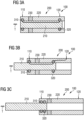
- the movable element 210 is now moved as shown in the Figures 3A, 3B and 3C moved to the left.
- FIG 3C The electrical switch 100 is shown in the OFF state.
- the transit movement T caused the movable element 210 to move further as shown in the Figures 3A, 3B and 3C moved to the left.
- the second contact system 320 has been moved beyond the galvanic isolation 230 so that the first contact system 310 and the second contact system 320 are both in the zone of the first contact 110.
- a current flow only occurs due to a leakage current of the galvanic isolation, since the resistance of the adjustable resistance element 200 is greater than 1M ⁇ (mega ohm).
- the adjustable resistance element 200 has a first zone 221, which is made of copper, for example, and has a high conductivity.
- the fixed element 220 dips into this first zone 221, so that due to the lowest resistance, the current flows over the front surface of the movable element 210 and the zone 221 with low conductivity of the adjustable resistance element 200.
- the movable element 210 also has a termination 211, which can also be made of copper and thus has a low conductivity. The current therefore flows from the first contact 110 via the termination 211 and the movable element 210.
- the movable element 210 is now moved further to the left, the first contact system 310 and the second contact system 320 are moved towards each other and the current flows through the adjustable resistance element 200 itself. As the movement is continued, the division of the current path between the movable element 210 and the fixed element 220 changes.
- the second contact system 320 reaches the zone of galvanic isolation 230.
- the switch is opened and a current flow is no longer possible.
- the first contact system 310 and the second contact system 320 are located in the zone of the first contact 110.
- the electrical switch 100 may have at least a third contact, wherein it commutates a potential between these at least three contacts.
- the adjustable resistance element 200 in particular its fixed element 220, can be made from a conventional material or from a dopable semiconductor material.
- Silicon carbide (SiC) for example, is advantageous as a dopable semiconductor material, since this material meets important criteria and enables a compact design of the adjustable resistance element 200.
- Silicon carbide as a semiconductor material has a very high breakdown field strength and a low specific forward resistance.
- silicon carbide can be doped and thus its electrical properties can be adjusted from 0.1 to 109 ⁇ cm (ohm centimeters).
- silicon carbide is high temperature resistant, the oxidation resistance is given up to 1600°C and the decomposition temperature is above 2700°C. Silicon carbide is also a very good heat conductor.
- the increase in the resistance of the adjustable resistance element 200 can be achieved by changing the active length, shape, arrangement or doping.
- the current path within the adjustable resistance element 200, or the division of the current path between the movable element 210 and the fixed element 220, is changed by the transit movement T.
- Figures 5A to 5D show the switching device 1000 according to the invention in its various intermediate states.
- the switching device 1000 can not only assume an ON state and an OFF state for opening, closing or commutating a circuit between a first contact 110 and a second contact 120, but also other intermediate states, wherein in the ON state the switching device and thus the circuit is closed and in the OFF state it is open.
- the switching device 1000 has a controllable resistance element 200, which is arranged electrically between the first contact 110 and the second contact 120.
- the state of the switching device 1000 is changed by means of a mechanical transit movement T.
- the transit movement T is carried out in such a way that the current voltage drop is smaller than the ignition voltage of an arc at any time and thus the switching energy in the adjustable resistance element 200 is dissipated in the form of electrical power loss.
- the transit movement T causes the adjustable resistance element 200 to be transferred into an intermediate state, so that an electrical damping is introduced into the circuit without interrupting it.
- the adjustable resistance element 200 comprises a movable element 210 and a fixed element 220, wherein the movable element 210 is essentially cylindrical and the fixed element 220 is essentially hollow cylindrical.
- the movable element 210 is designed to be immersible in the fixed element 220 and can be moved against it.
- first contact system 310 is provided on the movable element 210 and a second contact system 320 is provided on the fixed element 220 on the adjustable resistance element 200.
- These contact systems 310; 320 are provided for electrical contact between the movable element 210 and the fixed element 220.
- the linear transit movement T changes the distance between the first contact system 310 and the second contact system 320, which changes the division of the current path between the movable element 210 and the fixed element 220.
- This in the sequence of Figures 5A to 5F As a result of the movement of the movable element 210 to the left, the second contact system 320 is moved towards the first contact system 310 and the current path changes such that an ever larger proportion flows via the fixed element 220 of the adjustable resistance element 200.
- the set intermediate state can be exited again and the switching device 1000 can return to the ON state.
- the electrical switching device 1000 would not be triggered, but would only be temporarily transferred to an intermediate state.
- the switching device 1000 can force the circuit to open, i.e. to transfer it to the OFF state.
- the transit movement T can be carried out by means of an electromechanical drive.
- a first coil 520 is provided at the bottom of the hollow-cylindrical fixed element 220 and a second, corresponding coil 510 is provided at the first end of the cylindrical movable element 210, which repel each other when energized.
- a spring 600 is arranged at the second end of the cylindrical movable element 210, which presses the movable element 210 in the direction of the first coil 520 and thus in the direction of the ON state.
- the current supply to the first and second coils 520; 510 can be carried out by means of a control, which thus controls the transit movement T and the desired intermediate state or also sets the ON state or OFF state of the adjustable resistance element 200.
- a sensor for measuring the temperature of the adjustable resistance element 200 or the temperature of the main current path may be provided on the switching device 1000.
- the control can adjust the adjustable resistance element 200 according to the measured temperature and, if necessary, transfer the switching device 1000 to the OFF state so that no current flow is possible.
- the switching device 1000 is intended for switching an alternating current or a direct current.
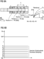
- the switching device 1000 according to the invention is shown with four different intermediate states with the resistors R1, R2, R3 and R4.
- the resistor R4 should be much larger than the resistor R3, which is much larger than the resistor R2 and which is larger than the resistor R1.
- the adjustable resistance element 200 will attenuate the circuit by means of the set resistance when set to one of the four intermediate states.
- Figure 6B explains the sequence of electrical resistances of the adjustable resistance element 200 clearly: Starting from the ON state with low resistance, discrete electrical resistances R1, R2, R3, R4, ..., RN can be set. Above the maximum resistance RN lies the electrical resistance of the OFF state. According to the Figures 5A to 5F and the formation of the adjustable resistance element 200, in this embodiment the resistance values are continuously formed and can be continuously controlled.
- the detection of the overcurrent and the deflection of the adjustable resistance element 200 can also be carried out by a corresponding
- the main contacts can be arranged without additional coil bodies or with additional measuring devices. This fulfills the function of a thermal release.
- the temperature can also be measured at certain points in the adjustable resistance element 200 or on the main current path for smaller currents. If the temperature exceeds a certain threshold, the movable contact system changes its position via a corresponding deflection mechanism, for example a bimetal, and the resistance is increased further. This reduces the current.
- a corresponding deflection mechanism for example a bimetal
- Such a system can either represent a function of the switching device 1000, which thereby protects the equipment connected in the circuit, or it can also be a type of self-protection of the device in order to ensure an overload of the adjustable resistance element 200 or parts of the current path.
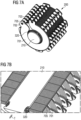
- FIGS 7A and 7B another embodiment of a controllable resistance element 200 is shown.
- uniform resistance elements 701 with a first connection surface 702 and a second connection surface 703 are connected in series.
- Insulation elements 705 are arranged between the resistance elements 701, so that the series connection takes place via the electrical contacting of adjacent connection surfaces 702, 703.
- Resistance elements 701 are designed as broken hollow disks with a first connection surface 702 and a second connection surface 703.
- the movable element 210 with the second contact system 320 runs inside the resistance elements 701, the movable element 210 with the second contact system 320 runs.
- the opening and closing takes place analogously to the first or second embodiment by means of a transit movement T, wherein the transit movement T is carried out in such a way that the current voltage drop is smaller than the ignition voltage at any time. an arc and thereby the switching energy in the adjustable resistance element 200 is dissipated in the form of electrical power loss.
Landscapes
- Engineering & Computer Science (AREA)
- Microelectronics & Electronic Packaging (AREA)
- Arc-Extinguishing Devices That Are Switches (AREA)
Description
- Die Erfindung betrifft ein Schaltgerät.
- Beim Öffnen, Schließen oder Kommutieren von Wechselstrom- oder Gleichstromkreisen entstehen Schaltlichtbögen. Diese Schaltlichtbögen geben typischerweise die freiwerdende Energie in entsprechenden Löscheinrichtungen ab, bis der Lichtbogen verlöscht. Herkömmliche elektrische Schalter versuchen die entstehenden Schaltlichtbögen zu kontrollieren. Vor allem bei der steigenden Anzahl an Gleichstromanwendungen, in denen kein Stromnulldurchgang erfolgt, ist dies mit beliebig viel technischem Aufwand verbunden.
- Bei bisherigen Leistungsschaltern mit einfach- oder zweifachunterbrechenden Kontakten, bei denen der Lichtbogen in Ionisierungslöschkammern, beispielsweise mit Hilfe von Slotmotoren, geleitet wird, wird ein entstehender Schaltlichtbogen in der Ionisierungslöschkammer gelöscht. Problematisch ist hierbei das Entstehen eines ionisierenden Gases bei hohen Temperaturen mit entsprechendem Materialabtrag und Verschmutzung des elektrischen Schalters.
- Ebenso kann ein elektrischer Strom ohne Schaltlichtbögen durch einen Halbleiterschalter geschaltet werden, der eine komplexe Ansteuerelektronik erfordert, und bei dem in der Regel keine sichere galvanische Trennung gewährleistet ist.
- Niederspannungsschaltgeräte erfüllen typischerweise Schutzfunktionen. Beispielsweise wird eine dieser Schutzfunktionen von einem Überstromauslöser gebildet. Dieser Überstromauslöser sorgt dafür, dass im Fehlerfall der Stromkreis unterbrochen wird. Bei kleinen Nennströmen kann die Reaktionszeit des Überstromauslösers im Sekundenbereich liegen. Bei höheren Nennströmen muss die Auslösung sehr schnell passieren. Die Auslöseschwelle muss typischerweise sehr fein einstellbar sein.
- In heute herkömmlichen Schaltgeräten detektieren Funktionseinheiten wie ETUs, TMTUs oder MTUs (Electronic Trip Unit, Thermo Mechanical Trip Unit, Magnetic Trip Unit) einen Überstrom zu Auslösung und lösen gegebenenfaslls eine Unterbrechung des Stromkreises aus. Konventionelle System kennen nur die Schalterzustände ON und OFF.
- In der
US 2012/199558 A1 wird ein kommutierender Leistungsschalter offenbart, der durch die physische Bewegung einer Pendelvorrichtung, die durch mindestens einen Satz elektrischer Schleifkontakte auf der Pendelvorrichtung den Strom durch die sich bewegende Pendelvorrichtung mit einer Folge unterschiedlicher Widerstände verbindet und somit mit dem Stromkreis verbunden ist, wobei ein zunehmender Widerstand in einen Stromkreis eingefügt wird. Die Bewegung der Pendelvorrichtung kann entweder linear oder rotierend sein. An keinem Punkt sind die gleitenden Statorelektroden von den passenden stationären Statorelektroden getrennt, um einen starken Lichtbogen zu erzeugen, der eine Beschädigung der gleitenden Statorelektroden minimiert. Stattdessen wird der Strom von einem Widerstandspfad zum nächsten mit ausreichend kleinen Widerstandsänderungen bei jedem Schritt kommutiert, so dass eine Lichtbogenbildung unterdrückt wird. - Die
EP 3 031 062 A1 offenbart einen mechanischen Schalter, der durch Kommutierung des Stroms zu einem energieabsorbierenden Pfad oder einer Folge von Pfaden durch mindestens einen Sperrhalbleiter arbeitet, um den Stromkreis zu öffnen, wobei die Kommutierung durch eine Gleitbewegung mindestens einer Pendel-Elektrode über mindestens eine stationäre Elektrode bewirkt wird. - Es ist daher Aufgabe der Erfindung, ein elektrisches Schaltergerät zur Verfügung zu stellen, welches Zwischenzustände zwischen dem ON-Zustand und dem OFF-Zustand eines elektrischen Schalters ermöglicht.
- Diese Aufgabe wird erfindungsgemäß durch das Schaltgerät gemäß Anspruch 1 gelöst. Vorteilhafte Ausgestaltungen des erfindungsgemäßen Schaltgeräts sind in den Unteransprüchen angegeben.
- Das Schaltgerät mit einem ON-Zustand, einem OFF-Zustand zum Öffnen, Schließen oder Kommutieren eines Stromkreises zwischen einem ersten Kontakt und einem zweiten Kontakt und weiteren Zwischenzuständen zwischen dem ON- und OFF-Zustand gemäß Anspruch 1 umfasst ein regelbares Widerstandselement, welches zwischen dem ersten Kontakt und dem zweiten Kontakt elektrisch angeordnet ist, wobei im ON-Zustand das Schaltgerät geschlossen ist und im OFF-Zustand geöffnet, wobei mittels einer mechanischen Transitbewegung der Zustand des Schaltgeräts geändert wird, wobei die Transitbewegung so ausgeführt wird, dass der aktuelle Spannungsfall zu jedem Zeitpunkt kleiner ist als die Zündspannung eines Lichtbogens und dadurch die Schalt-Energie im regelbaren Widerstandselement in Form von elektrischer Verlustleistung abgeführt wird, und wobei bei Überströmen unterhalb eines Überstrom-Schwellwertes durch die Transitbewegung das regelbare Widerstandselement in einen Zwischenzustand überführt wird, so dass eine elektrische Dämpfung in den Stromkreis eingebracht wird ohne eine Unterbrechung desselben. Das regelbare Widerstandselement umfasst ein bewegliches Element und ein feststehendes Element, wobei das bewegliche Element im Wesentlichen zylinderförmig ausgebildet ist, wobei das feststehende Element im Wesentlichen hohlzylinderförmig ausgebildet ist, wobei das bewegliche Element in das feststehende Element eintauchbar ausgebildet ist und gegen dieses bewegt werden kann, wobei ein erstes Kontaktsystem am beweglichen Element und ein zweites Kontaktsystem am feststehenden Element angebracht ist jeweils zur elektrischen Kontaktierung zwischen dem beweglichen Element und dem feststehenden Element, und wobei durch die lineare Transitbewegung der Abstand zwischen dem ersten Kontaktsystem und dem zweiten Kontaktsystem geändert wird, wodurch sich die Aufteilung des Strompfads zwischen beweglichem Element und feststehendem Element ändert.
- Vorteilhaft hierbei ist, dass ein solches Schaltgerät zu den beiden Schaltzuständen ON und OFF noch zusätzliche Zwischenschaltzustände zur Verfügung stellt, nämlich Schaltzustände in denen der Stromkreis definiert bedämpft wird. Bei folgenden Anwendungen ergeben entscheidende Vorteile:
- Anwendungen bei denen der Stromkreis aus Gründen von hoher Verfügbarkeit nicht getrennt werden darf, jedoch trotzdem ein ausreichender Schutz gegen Überstrom gewährleistet sein muss;
- Anwendungen bei denen unterbrechungsfrei zwischen zwei Potentialen umgeschaltetet werden soll. Im Gegensatz zu einem "harten" Trennen von Stromkreisen wird das Fliesen von Ausgleichsströmen ermöglicht. Das Funktionsprinzip ähnelt dem von Widerstandsschnellschaltern.
- Anwendungen mit sich stark ändernden Lasten, wie beispielsweise Elektrolyseöfen in Stahlschmelzen, oder elektrogalvanische Prozesse, bei denen die Betriebsmittel deshalb nur sehr schwer abzusichern sind.
- In einer Ausgestaltung wird beim Absinken des Überstroms der Zwischenzustand verlassen und der ON-Zustand eingenommen.
- In einer weiteren Ausgestaltung wird bei Überströmen oberhalb des Überstrom-Schwellwerts das Öffnen des Stromkreises (OFF-Zustand) erzwungen.
- In einer weiteren Ausgestaltung wird die Transitbewegung durch eine Regelung eingestellt.
- In einer Ausgestaltung sind am regelbaren Widerstandselement Spulen vorgesehen zum elektro-mechanischen Antrieb gegen eine Feder.
- In einer weiteren Ausgestaltung ist am Boden des hohlzylinderförmig ausgebildeten feststehenden Elements eine erste Spule und am ersten Ende des zylinderförmig ausgebildeten beweglichen Elements eine zweite, korrespondierende Spule angeordnet, wobei sich bei Bestromung die beiden Spulen voneinander abstoßen, wobei am gegenüberliegenden, zweiten Ende des zylinderförmig ausgebildeten beweglichen Elements eine Feder das bewegliche Element in Richtung der ersten Spule und somit in Richtung des ON-Zustands drückt.
- In einer Ausgestaltung umfasst das Schaltgerät weiterhin einen Sensor zur Messung der Temperatur des regelbaren Widerstandselements oder der Hauptstrombahn.
- In einer weiteren Ausgestaltung ist das Schaltgerät zum Schalten eines Wechsel- oder Gleichstroms vorgesehen.
- Die oben beschriebenen Eigenschaften, Merkmale und Vorteile dieser Erfindung, sowie die Art und Weise, wie sie erreicht werden, werden klarer und deutlicher verständlich im Zusammenhang mit der folgenden Beschreibung der Ausführungsformen, die im Zusammenhang mit den Figuren näher erläutert werden.
- Dabei zeigen:
-
Figur 1 : Elektrischer Schalter mit regelbarem Widerstandselement; -
Figuren 2A und 2B : Elektrischer Widerstand des erfindungsgemäßen elektrischen Schalters; -
Figuren 3A, 3B, 3C : Elektrischer Schalter mit regelbarem Widerstandselement im ON-Zustand, Zwischenzustand und OFF-Zustand; -
Figuren 4A, 4B, 4C ,4D, 4E, 4F ,4G, 4H, 4I, 4J : Transitbewegung des erfindungsgemäßen elektrischen Schalters zwischen ON-Zustand und OFF-Zustand; -
Figur 5A, 5B, 5C ,5D, 5E, 5F : Schaltgerät mit regelbarem Widerstandselement und Spulen und Feder; -
Figur 6A und 6B : Dämpfung eines Stromkreises mit erfindungsgemäßen Schaltgerät und Schaltzustände des Schaltgeräts; und -
Figur 7A und 7B : Weitere Ausführungsform eines regelbaren Widerstandselements. - In
Figur 1 ist ein elektrischer Schalter 100 dargestellt. Der elektrische Schalter 100 umfasst einen ON-Zustand und einen OFF-Zustand zum Öffnen, Schließen oder Kommutieren eines Stromkreises. Dazu ist ein erster Kontakt 110 und ein zweiter Kontakt 120 vorgesehen, zwischen denen der Stromkreis geschaltet wird. Weiter umfasst der elektrische Schalter 100 ein regelbares Widerstandselement 200, welches zwischen dem ersten Kontakt 110 und dem zweiten Kontakt 120 elektrisch angeordnet ist. Im ON-Zustand ist der elektrische Schalter 100 geschlossen und im OFF-Zustand geöffnet. Der Schaltvorgang, die Überführung des ON-Zustands in den OFF-Zustand und umgekehrt, geschieht mittels einer mechanischen Transitbewegung T des regelbaren Widerstandselements 200. - Zum Öffnen oder Kommutieren des Stromkreises wird mittels der Transitbewegung T der Widerstand des regelbaren Widerstandselements 200 erhöht und die Transitbewegung T wird so ausgeführt, dass der aktuelle Spannungsfall zu jedem Zeitpunkt kleiner ist als die Zündspannung eines Lichtbogens und dass dadurch die Schaltenergie im regelbaren Widerstandselement 200 in Form von elektrischer Verlustleistung abgeführt wird.
- Das regelbare Widerstandselement 200 umfasst ein bewegliches Element 210 und ein feststehendes Element 220, wobei das bewegliche Element 210 im wesentlichen zylinderförmig ausgebildet ist und das feststehende Element im wesentlichen hohlzylinderförmig. Das bewegliche Element 210 kann in das feststehende Element 220 eintauchen und gegen dieses bewegt werden. Weiterhin umfasst das regelbare Widerstandselement 200 ein erstes Kontaktsystem 310 am feststehenden Element 220 und ein zweites Kontaktsystem 320 am beweglichen Element 210 jeweils zur elektrischen Kontaktierung zwischen dem beweglichen Element 210 und dem feststehenden Element 220.
- Durch eine lineare Transitbewegung T wird der Abstand zwischen dem ersten Kontaktsystem 310 und dem zweiten Kontaktsystem 320 geändert, wodurch sich die Aufteilung des Strompfads zwischen beweglichem Element 210 und feststehendem Element 220 ändert.
- Das feststehende Element 220 kann eine galvanische Isolation 230 umfassen, sodass im OFF-Zustand der erste Kontakt 110 galvanisch getrennt ist vom zweiten Kontakt 120. Ebenso kann die galvanische Trennung über die Dotierung des regelbaren Widerstandselements 200 selbst geschehen.
- In
Figur 2A ist die Kette der elektrischen Widerstände des elektrischen Schalters 100 dargestellt. Es handelt sich um eine Reihenschaltung an elektrischen Widerständen, angefangen vom elektrischen Widerstand am zweiten Kontakt 120 R_Cu2 über den Widerstand des regelbaren Widerstandselements 200 R_SiC und dem elektrischen Widerstand der galvanischen Isolation 230 R_Iso zum ersten Kontakt 110 mit dem Widerstand R_Cu1. - In
Figur 2B ist der elektrische Widerstand des regelbaren Widerstandselements 200 dargestellt aufgetragen über der Auslenkung der mechanischen Transitbewegung T. In der Darstellung derFigur 2B ist bei kleinen Positionen der erste Kontakt 110 galvanisch getrennt vom zweiten Kontakt 120 bei einem elektrischen Widerstand größer 1MΩ (Mega Ohm). In dieser linken Position -bei einem elektrischen Widerstand größer 1MΩ (Mega Ohm)- befindet sich der elektrische Schalter 100 im OFF-Zustand. - Fährt nun mittels der mechanischen Transitbewegung T das bewegliche Element 210 entsprechend der Darstellung der
Figur 1 nach rechts, so nimmt der Widerstand nach dem Überschreiten der Isolationszone 230 ab, bis zu einem elektrischen Widerstand des regelbaren Widerstandselement kleiner 100µΩ (Mikro Ohm). In dieser Stellung befindet sich der elektrische Schalter im ON-Zustand. - In den
Figuren 3A, 3B und 3C wird die Überführung des elektrischen Schalters 100 vom ON-Zustand in den OFF-Zustand dargestellt. Mittels einer linearen Transitbewegung T des beweglichen Elements 210 wird der Widerstand des regelbaren Widerstandselements 200 erhöht, wobei die Transitbewegung T so ausgeführt wird, dass der aktuelle Spannungsfall zu jedem Zeitpunkt kleiner ist als die Zündspannung eines Lichtbogens und dadurch die Schaltenergie im regelbaren Widerstandselement 200 in Form von elektrischer Verlustleistung abgeführt wird. - In
Figur 3A befindet sich der elektrische Schalter 100 im ON-Zustand. Der elektrische Strom fließt vom ersten Kontakt 110 über das erste Kontaktsystem 310 zum beweglichen Element 210 und weiter über das zweite Kontaktsystem 320 zum zweiten Kontakt 120. Ist das bewegliche Element 210 beispielsweise aus Kupfer gefertigt, so ist der Gesamtwiderstand des elektrischen Schalters in der ON-Stellung im Bereich kleiner 100µΩ (Mikro Ohm). Das erste Kontaktsystem 310 und das zweite Kontaktsystem 320 wird von Kontaktfedern gebildet, beispielsweise von Canted-Coil-Federn der Firma Bal Seal Engineering. - Zum Auslösen des elektrischen Schalters 100, also zum Überführen des elektrischen Schalters 100 vom ON-Zustand in den OFF-Zustand, wird nun das bewegliche Element 210 entsprechend der Darstellung in den
Figuren 3A, 3B und 3C nach links bewegt. - In einer Zwischenstellung, die in
Figur 3B dargestellt ist, fließt der Strom wiederrum vom ersten Kontakt 110 über das erste Kontaktsystem 310, dem beweglichen Element 210 zum zweiten Kontaktsystem 320 und im regelbaren Widerstandselement 200 zum zweiten Kontakt 120. Durch die lineare Transitbewegung T wurde der Abstand zwischen dem ersten Kontaktsystem 310 und dem zweiten Kontaktsystem 320 geändert, nämlich verringert, wodurch sich die Aufteilung des Strompfads zwischen beweglichem Element 210 und feststehendem Element 220 ändert. - In
Figur 3C ist der elektrische Schalter 100 im OFF-Zustand dargestellt. Durch die Transitbewegung T wurde das bewegliche Element 210 weiter entsprechend der Darstellung derFiguren 3A, 3B und 3C nach links bewegt. Das zweite Kontaktsystem 320 wurde über die galvanische Isolation 230 hinausbewegt, sodass das erste Kontaktsystem 310 und das zweite Kontaktsystem 320 beide in der Zone des ersten Kontakts 110 sind. Somit geschieht ein Stromfluss nur aufgrund eines Kriechstroms der galvanischen Trennung, da der Widerstand des regelbaren Widerstandselement 200 größer 1MΩ (Mega Ohm) ist. - In den
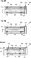
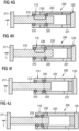
Figuren 4A bis 4J wird ein elektrischer Schalter 100 dargestellt. Das regelbare Widerstandselement 200 weist eine erste Zone 221 auf, die beispielsweise aus Kupfer gestaltet ist und eine hohe Leitfähigkeit hat. Im ON-Zustand des elektrischen Schalters taucht das feststehende Element 220 in diese erste Zone 221 ein, sodass aufgrund des geringsten Widerstands der Strom über die Stirnfläche des beweglichen Elements 210 und der Zone 221 mit geringer Leitfähigkeit des regelbaren Widerstandselements 200 fließt. Ebenso weist das bewegliche Element 210 einen Abschluss 211 auf, der ebenfalls aus Kupfer gefertigt sein kann und somit eine geringe Leitfähigkeit hat. Der Strom fließt daher vom ersten Kontakt 110 über den Abschluss 211 und das bewegliche Element 210. - Wird nun die Transitbewegung T ausgeführt, entsprechend der Darstellung der
Figuren 4A bis 4J der Bewegung des beweglichen Elements 210 nach links, so kommt es zu einer räumlichen Separation des Abschlusses 211 und auch des beweglichen Elements 210 von der Zone 221, so dass der Strom über das erste Kontaktsystem 310 und das zweite Kontaktsystem 320 fließt. - Wird nun das bewegliche Element 210 weiter nach links bewegt, so werden das erste Kontaktsystem 310 und das zweite Kontaktsystem 320 aufeinander zubewegt und der Strom fließt durch das regelbare Widerstandselement 200 selbst. Bei weiterer Durchführung der Bewegung ändert sich die Aufteilung des Strompfads zwischen dem beweglichen Element 210 und dem feststehenden Element 220.
- In
Figur 4H erreicht das zweite Kontaktsystem 320 die Zone der galvanischen Isolation 230. Wenn nun das zweite Kontaktsystem 320 vollständig in der Zone der galvanischen Isolation 230 ist, ist der Schalter geöffnet und ein Stromfluss nicht mehr möglich. In der Endposition des beweglichen Elements 210 in der Darstellung derFigur 4J befinden sich das erste Kontaktsystem 310 und das zweite Kontaktsystem 320 in der Zone des ersten Kontakts 110. - Der elektrische Schalter 100 kann mindestens einen dritten Kontakt aufweisen, wobei von ihm ein Potenzial zwischen diesen mindestens drei Kontakten kommutiert wird.
- Das regelbare Widerstandselement 200, insbesondere sein feststehendes Element 220, kann aus einem konventionellen Material oder aus einem dotierbaren Halbleitermaterial hergestellt sein. Als dotierbares Halbleitermaterial ist beispielsweise Siliciumcarbid (SiC) vorteilhaft, da dieses Material wichtige Kriterien erfüllt und eine kompakte Bauweise des regelbaren Widerstandselements 200 ermöglicht. Siliciumcarbid als Halbleitermaterial hat eine sehr hohe Durchbruchfeldstärke und einen geringen spezifischen Durchlasswiderstand. Des Weiteren ist Siliciumcarbid dotierbar und damit in den elektrischen Eigenschaften einstellbar von 0,1 bis 109 Ω·cm (Ohm Zentimeter). Weiter ist Siliciumcarbid hochtemperaturbeständig, die Oxidationsbeständigkeit ist bis 1600°C gegeben und die Zersetzungstemperatur liegt über 2700°C. Ebenso ist Siliciumcarbid ein sehr guter Wärmeleiter.
- Die Erhöhung des Widerstands des regelbaren Widerstandselements 200 kann über eine Änderung der aktiven Länge, der Form, der Anordnung oder der Dotierung geschehen. Der Strompfad innerhalb des regelbaren Widerstandselements 200, beziehungsweise die Aufteilung des Strompfads zwischen dem beweglichen Element 210 und dem feststehenden Element 220, wird durch die Transitbewegung T geändert.
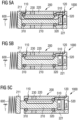
-
Figuren 5A bis 5D zeigen das erfindungsgemäße Schaltgerät 1000 in seinen verschiedenen Zwischenzuständen. Das Schaltgerät 1000 kann zum Öffnen, Schließen oder Kommutieren eines Stromkreises zwischen einem ersten Kontakt 110 und einem zweiten Kontakt 120 nicht nur einen ON-Zustand und einen OFF-Zustand einnehmen, sonders weitere Zwischenzustände, wobei im ON-Zustand das Schaltgerät und damit der Stromkreis geschlossen ist und im OFF-Zustand geöffnet. - Das Schaltgerät 1000 weist dazu ein regelbares Widerstandselement 200 auf, welches elektrisch zwischen dem ersten Kontakt 110 und dem zweiten Kontakt 120 angeordnet ist. Der Zustand des Schaltgeräts 1000 wird mittels einer mechanischen Transitbewegung T geändert.
- Dabei wird die Transitbewegung T so ausgeführt, dass der aktuelle Spannungsfall zu jedem Zeitpunkt kleiner ist als die Zündspannung eines Lichtbogens und dadurch die Schalt-Energie im regelbaren Widerstandselement 200 in Form von elektrischer Verlustleistung abgeführt wird.
- Bei Überströmen unterhalb eines Überstrom-Schwellwertes wird durch die Transitbewegung T das regelbare Widerstandselement 200 in einen Zwischenzustand überführt wird, sodass eine elektrische Dämpfung in den Stromkreis eingebracht wird ohne eine Unterbrechung desselben.
- In der
Figur 5A befindet sich das Schaltgerät 1000 zunächst im ON-Zustand. Das regelbare Widerstandselement 200 umfasst ein bewegliches Element 210 und ein feststehendes Element 220, wobei das bewegliche Element 210 im Wesentlichen zylinderförmig ausgebildet ist und das feststehende Element 220 im Wesentlichen hohlzylinderförmig. Das bewegliche Element 210 ist in das feststehende Element 220 eintauchbar ausgebildet und kann gegen dieses bewegt werden. - Weiterhin ist am regelbaren Widerstandselement 200 ein erstes Kontaktsystem 310 am beweglichen Element 210 und ein zweites Kontaktsystem 320 am feststehenden Element 220 vorgesehen. Diese Kontaktsysteme 310; 320 sind zur elektrischen Kontaktierung zwischen dem beweglichen Element 210 und dem feststehenden Element 220 vorgesehen.
- Durch die lineare Transitbewegung T wird der Abstand zwischen dem ersten Kontaktsystem 310 und dem zweiten Kontaktsystem 320 geändert, wodurch sich die Aufteilung des Strompfads zwischen beweglichem Element 210 und feststehendem Element 220 ändert. Dies in der Sequenz der
Figuren 5A bis 5F dargestellt. Durch die Bewegung des beweglichen Elements 210 nach links wird das zweite Kontaktsystem 320 auf das erste Kontaktsystem 310 zubewegt und es ändert sich der Strompfad so, dass ein immer größerer Anteil über das feststehende Element 220 des regelbaren Widerstandselements 200 fließt. - Bei einem Absinken des Überstroms kann der eingestellte Zwischenzutand wieder verlassen werden und das Schaltgerät 1000 in den ON-Zustand zurückkehren. In solch einem Fall würde das elektrische Schaltgerät 1000 nicht ausgelöst, sondern nur temporär in einen Zwischenzustand überführt.
- Wenn nach dem Überführen des regelbaren Widerstandselements 200 in einen Zwischenzustand wegen des Auftreten eines Überstroms unterhalb eines Überstrom-Schwellwerts der Überstrom weiter steigt und den Überstrom-Schwellwert übersteigt, so kann vom Schaltgerät 1000 ein Öffnen des Stromkreies, also ein Überführen in den OFF-Zustand, erzwungen werden.
- Die Transitbewegung T kann mittels eines elektromechanischen Antriebs geschehen. In den
Figuren 5A bis 5F sind dafür eine erste Spule 520 am Boden des hohlzylinderförmig ausgebildeten feststehenden Elements 220 und am ersten Ende des zylinderförmig ausgebildeten beweglichen Elements 210 eine zweite, korrespondierende Spule 510 vorgesehen, die sich bei Bestromung voneinander abstoßen. Weiter ist am zweiten Ende des zylinderförmig ausgebildeten beweglichen Elements 210 eine Feder 600 angeordnet, die das bewegliche Element 210 in Richtung der ersten Spule 520 und somit in Richtung des ON-Zustands drückt. - Die Bestromung der ersten und zweiten Spule 520; 510 kann mittels einer Regelung vorgenommen werden, die somit die Transitbewegung T regelt und den gewünschten Zwischenzustand oder auch den ON-Zustand oder OFF-Zustand des regelbaren Widerstandselements 200 einstellt.
- Am Schaltgerät 1000 kein ein Sensor zur Messung der Temperatur des regelbaren Widerstandselements 200 oder der Temperatur der Hauptstrombahn vorgesehen sein. Die Regelung kann entsprechend der gemessenen Temperatur das regelbare Widerstandselement 200 einregeln und gegebenenfalls das Schaltgerät 1000 in den OFF-Zustand überführen, so dass kein Stromfluss mehr möglich ist.
- Das erfindungsgemäße Schaltgerät 1000 ist zum Schalten eines Wechsel- oder eines Gleichstroms vorgesehen.
- In
Figur 6A ist das erfindungsgemäße Schaltgerät 1000 dargestellt mit vier unterschiedlichen Zwischenzuständen mit den Widerständen R1, R2, R3 und R4. Beispielsweise soll gelten, dass der Widerstand R4 sehr viel größer als der Widerstand R3, dieser viel größer als der Widerstand R2 und dieser größer als der Widerstand R1 ist. Das regelbare Widerstandselement 200 wird bei Einstellung auf einen der vier Zwischenzustände den Stromkreis mittels des eingestellten Widerstands dämpfen. -
Figur 6B erläutert die Abfolge der elektrischen Widerstände des regelbaren Widerstandselemtns 200 anschaulich: Ausgehend vom ON-Zustand mit geringem Widerstand können diskrete elektrische Widerstände R1, R2, R3, R4, ..., RN eingestellt werden. Oberhalb vom maximalen Widerstand RN liegt der elektrische Widerstand des OFF-Zustands. Entsprechend derFiguren 5A bis 5F und der Ausbildung des regelbaren Widerstandselements 200 sind in dieser Ausführungsform die Widerstandswerte kontinuierlich ausgebildet und können kontinuierlich angesteuert werden. - Die Detektion des Überstroms und die Auslenkung des regelbaren Widerstandelements 200 kann auch durch eine entsprechende Anordnung der Hauptkontakte ohne zusätzliche Spulenkörper, oder durch zusätzliche Messeinrichtungen erfolgen. Damit wird die Funktion eines thermischen Auslösers erfüllt.
- Zusätzlich zu der definierten Auslenkung aufgrund eines bestimmten Stroms, kann bei kleineren Strömen noch die Temperatur an bestimmten Punkten im regelbaren Widerstandselement 200 oder auf der Hauptstrombahn gemessen werden. Überschreitet die Temperatur eine bestimmte Schwelle, so ändert das bewegliche Kontaktsystem über eine entsprechende Auslenkmechanik, beispielsweise ein Bimetall, seine Position und der Widerstand wird weiter erhöht. Dadurch wird der Strom reduziert.
- Ein solches System kann sowohl eine Funktion des Schaltgerätes 1000 darstellen, dass damit die im Stromkreis angeschlossenen Betriebsmittel schützt, oder auch eine Art Selbstschutz des Gerätes sein um eine Überlastung des regelbaren Widerstandselements 200 oder Teile der Strombahn zu gewährleisten.
- In den
Figuren 7A und 7B ist eine weitere Ausführungsform eines regelbaren Widerstandselements 200 dargestellt. In dieser Ausführungsform werden gleichförmige Widerstandselemente 701 mit erster Anschlussfläche 702 und zweiter Anschlussfläche 703 in Reihe geschaltet. Zwischen den Widerstandselementen 701 sind Isolationselemente 705 angeordnet, so dass die Reihenschaltung über die elektrische Kontaktierung benachbarter Anschlussfläche 702, 703 geschieht. Widerstandselementen 701 sind als aufgebrochene Hohlscheiben mit erster Anschlussfläche 702 und zweiter Anschlussfläche 703 ausgebildet. - Im Innern der Widerstandselementen 701 verläuft das bewegliche Element 210 mit dem zweiten Kontaktsystem 320. Das Öffnen und Schließen erfolgt analog zu der ersten oder zweiten Ausführungsform mittels einer Transitbewegung T, wobei die Transitbewegung T so ausgeführt wird, dass der aktuelle Spannungsfall zu jedem Zeitpunkt kleiner ist als die Zündspannung eines Lichtbogens und dadurch die Schalt-Energie im regelbaren Widerstandselement 200 in Form von elektrischer Verlustleistung abgeführt wird.
Claims (8)
- Schaltgerät (1000) mit einem ON-Zustand, einem OFF-Zustand zum Öffnen, Schließen oder Kommutieren eines Stromkreises zwischen einem ersten Kontakt (110) und einem zweiten Kontakt (120) und weiteren Zwischenzuständen zwischen dem ON- und OFF-Zustand sowie mit einem regelbaren Widerstandselement (200), welches zwischen dem ersten Kontakt (110) und dem zweiten Kontakt (120) elektrisch angeordnet ist, wobei im ON-Zustand das Schaltgerät (1000) geschlossen ist und im OFF-Zustand geöffnet, wobei mittels einer mechanischen Transitbewegung (T) der Zustand des Schaltgeräts (1000) geändert wird,
dadurch gekennzeichnet, dassdie Transitbewegung (T) so ausgeführt wird, dass der aktuelle Spannungsfall zu jedem Zeitpunkt kleiner ist als die Zündspannung eines Lichtbogens und dadurch die Schalt-Energie im regelbaren Widerstandselement (200) in Form von elektrischer Verlustleistung abgeführt wird, unddass bei Überströmen unterhalb eines Überstrom-Schwellwertes durch die Transitbewegung (T) das regelbare Widerstandselement (200) in einen Zwischenzustand überführt wird, so dass eine elektrische Dämpfung in den Stromkreis eingebracht wird ohne eine Unterbrechung desselben,
wobei das regelbare Widerstandselement (200) ein bewegliches Element (210) und ein feststehendes Element (220) umfasst,wobei das bewegliche Element (210) im Wesentlichen zylinderförmig ausgebildet ist,wobei das feststehende Element (220) im Wesentlichen hohlzylinderförmig ausgebildet ist,wobei das bewegliche Element (210) in das feststehende Element (220) eintauchbar ausgebildet ist und gegen dieses bewegt werden kann,wobei ein erstes Kontaktsystem (310) am beweglichen Element (210) und ein zweites Kontaktsystem (320) am feststehenden Element (220) angebracht ist jeweils zur elektrischen Kontaktierung zwischen dem beweglichen Element (210) und dem feststehenden Element (220),wobei durch die lineare Transitbewegung (T) der Abstand zwischen dem ersten Kontaktsystem (310) und dem zweiten Kontaktsystem (320) geändert wird, wodurch sich die Aufteilung des Strompfads zwischen beweglichem Element (210) und feststehendem Element (220) ändert. - Schaltgerät (1000) gemäß Anspruch 1, bei dem beim Absinken des Überstroms der Zwischenzustand verlassen wird und der ON-Zustand eingenommen wird.
- Schaltgerät (1000) gemäß Anspruch 1 oder 2, bei dem bei Überströmen oberhalb des Überstrom-Schwellwerts das Öffnen des Stromkreises (OFF-Zustand) erzwungen wird.
- Schaltgerät (1000) gemäß einem der vorherigen Ansprüche, bei dem die Transitbewegung (T) durch eine Regelung eingestellt wird.
- Schaltgerät (1000) gemäß Anspruch 4, bei dem am regelbaren Widerstandselement (200) Spulen (510; 520) vorgesehen sind zum elektromechanischen Antrieb gegen eine Feder (600) .
- Schaltgerät (1000) gemäß Anspruch 1, bei dem am Boden des hohlzylinderförmig ausgebildeten feststehenden Elements (220) eine erste Spule (520) und am ersten Ende des zylinderförmig ausgebildeten beweglichen Elements (210) eine zweite, korrespondierende Spule (510) angeordnet sind, wobei sich bei Bestromung die beiden Spulen (510; 520) voneinander abstoßen,
wobei am gegenüberliegenden, zweiten Ende des zylinderförmig ausgebildeten beweglichen Elements (210) eine Feder (600) das bewegliche Element (210) in Richtung der ersten Spule (520) und somit in Richtung des ON-Zustands drückt. - Schaltgerät (1000) gemäß einem der vorherigen Ansprüche, bei dem das Schaltgerät (1000) weiterhin einen Sensor zur Messung der Temperatur des regelbaren Widerstandselements (200) oder der Hauptstrombahn umfasst.
- Schaltgerät (1000) gemäß einem der vorherigen Ansprüche, wobei das Schaltgerät (1000) zum Schalten eines Wechsel- oder Gleichstroms vorgesehen ist.
Applications Claiming Priority (1)
| Application Number | Priority Date | Filing Date | Title |
|---|---|---|---|
| PCT/EP2019/067628 WO2021001017A1 (de) | 2019-07-01 | 2019-07-01 | Schaltgerät |
Publications (2)
| Publication Number | Publication Date |
|---|---|
| EP3956915A1 EP3956915A1 (de) | 2022-02-23 |
| EP3956915B1 true EP3956915B1 (de) | 2025-01-08 |
Family
ID=67297134
Family Applications (1)
| Application Number | Title | Priority Date | Filing Date |
|---|---|---|---|
| EP19739933.0A Active EP3956915B1 (de) | 2019-07-01 | 2019-07-01 | Schaltgerät |
Country Status (2)
| Country | Link |
|---|---|
| EP (1) | EP3956915B1 (de) |
| WO (1) | WO2021001017A1 (de) |
Families Citing this family (1)
| Publication number | Priority date | Publication date | Assignee | Title |
|---|---|---|---|---|
| DE102021200648B4 (de) | 2021-01-26 | 2024-05-23 | Siemens Aktiengesellschaft | Elektrischer Schalter mit einem regelbaren Widerstandselement |
Family Cites Families (2)
| Publication number | Priority date | Publication date | Assignee | Title |
|---|---|---|---|---|
| US8890019B2 (en) * | 2011-02-05 | 2014-11-18 | Roger Webster Faulkner | Commutating circuit breaker |
| CN105723489B (zh) * | 2013-08-05 | 2019-06-04 | 英诺锂资产公司 | 具有阻断半导体的换向开关 |
-
2019
- 2019-07-01 WO PCT/EP2019/067628 patent/WO2021001017A1/de not_active Ceased
- 2019-07-01 EP EP19739933.0A patent/EP3956915B1/de active Active
Also Published As
| Publication number | Publication date |
|---|---|
| EP3956915A1 (de) | 2022-02-23 |
| WO2021001017A1 (de) | 2021-01-07 |
Similar Documents
| Publication | Publication Date | Title |
|---|---|---|
| EP2553691B1 (de) | Überspannungsschutzeinrichtung, umfassend mindestens einen überspannungsableiter | |
| EP3529817B1 (de) | Niederspannungs-schutzschaltgerät | |
| EP2319143B1 (de) | Überspannungsableiter mit mindestens einem ableitelement | |
| DE102015217704A1 (de) | Lichtbogen-Löschvorrichtung und Schutzschaltgerät | |
| DE3738647A1 (de) | Unterbrecher fuer schutzvorrichtung | |
| EP2747110B1 (de) | Temperaturschutzschaltung | |
| EP3046124A1 (de) | Schalt- und schutzeinrichtung für hochvolt-bordnetze | |
| EP3428942B1 (de) | Gleichstrom-lichtbogenlöschvorrichtung und elektromechanisches gleichstrom-schaltgerät | |
| EP3688780A1 (de) | Niederspannungs-schutzschaltgerät | |
| EP2555217B1 (de) | Strombegrenzungssystem | |
| EP0750788B1 (de) | Schalter zur strombegrenzung | |
| EP4199026B1 (de) | Schutzschalter | |
| DE3824027A1 (de) | Elektrisches schaltgeraet | |
| WO1999017415A1 (de) | Leistungsschaltereinrichtung zur energieversorgung und -verteilung | |
| EP1644952B1 (de) | Verfahren und vorrichtung zur strombegrenzung mit einem selbstbetätigten strombegrenzer | |
| EP3959734B1 (de) | Elektrischer schalter | |
| EP3953957B1 (de) | Verfahren zur unterbrechungsfreien anpassung von parametern eines stromkreises | |
| EP3956915A1 (de) | Schaltgerät | |
| EP3084794B1 (de) | Schaltgerät | |
| EP3101678B1 (de) | Stromunterbrecher | |
| EP3889986B1 (de) | Elektromechanisches kompakt-schutzschaltgerät | |
| EP1735803A1 (de) | Schaltvorrichtung | |
| DE69505772T2 (de) | Gasisoliertes Hochspannungsgerät mit einem Lichtbogenkurzschlusselement | |
| DE102007004528B3 (de) | Elektrisches Gleichstromnetz für Wasserfahrzeuge sowie für Offshoreanlagen mit erhöhter Abschaltsicherheit | |
| EP3050069B1 (de) | Schalteinrichtung sowie ausschaltverfahren zum betrieb einer schalteinrichtung |
Legal Events
| Date | Code | Title | Description |
|---|---|---|---|
| STAA | Information on the status of an ep patent application or granted ep patent |
Free format text: STATUS: UNKNOWN |
|
| STAA | Information on the status of an ep patent application or granted ep patent |
Free format text: STATUS: THE INTERNATIONAL PUBLICATION HAS BEEN MADE |
|
| PUAI | Public reference made under article 153(3) epc to a published international application that has entered the european phase |
Free format text: ORIGINAL CODE: 0009012 |
|
| STAA | Information on the status of an ep patent application or granted ep patent |
Free format text: STATUS: REQUEST FOR EXAMINATION WAS MADE |
|
| 17P | Request for examination filed |
Effective date: 20211118 |
|
| AK | Designated contracting states |
Kind code of ref document: A1 Designated state(s): AL AT BE BG CH CY CZ DE DK EE ES FI FR GB GR HR HU IE IS IT LI LT LU LV MC MK MT NL NO PL PT RO RS SE SI SK SM TR |
|
| DAV | Request for validation of the european patent (deleted) | ||
| DAX | Request for extension of the european patent (deleted) | ||
| STAA | Information on the status of an ep patent application or granted ep patent |
Free format text: STATUS: EXAMINATION IS IN PROGRESS |
|
| 17Q | First examination report despatched |
Effective date: 20231122 |
|
| GRAP | Despatch of communication of intention to grant a patent |
Free format text: ORIGINAL CODE: EPIDOSNIGR1 |
|
| STAA | Information on the status of an ep patent application or granted ep patent |
Free format text: STATUS: GRANT OF PATENT IS INTENDED |
|
| INTG | Intention to grant announced |
Effective date: 20240819 |
|
| GRAS | Grant fee paid |
Free format text: ORIGINAL CODE: EPIDOSNIGR3 |
|
| GRAA | (expected) grant |
Free format text: ORIGINAL CODE: 0009210 |
|
| STAA | Information on the status of an ep patent application or granted ep patent |
Free format text: STATUS: THE PATENT HAS BEEN GRANTED |
|
| AK | Designated contracting states |
Kind code of ref document: B1 Designated state(s): AL AT BE BG CH CY CZ DE DK EE ES FI FR GB GR HR HU IE IS IT LI LT LU LV MC MK MT NL NO PL PT RO RS SE SI SK SM TR |
|
| REG | Reference to a national code |
Ref country code: GB Ref legal event code: FG4D Free format text: NOT ENGLISH |
|
| REG | Reference to a national code |
Ref country code: CH Ref legal event code: EP |
|
| REG | Reference to a national code |
Ref country code: DE Ref legal event code: R096 Ref document number: 502019012776 Country of ref document: DE |
|
| REG | Reference to a national code |
Ref country code: IE Ref legal event code: FG4D Free format text: LANGUAGE OF EP DOCUMENT: GERMAN |
|
| REG | Reference to a national code |
Ref country code: LT Ref legal event code: MG9D |
|
| REG | Reference to a national code |
Ref country code: NL Ref legal event code: MP Effective date: 20250108 |
|
| PG25 | Lapsed in a contracting state [announced via postgrant information from national office to epo] |
Ref country code: NL Free format text: LAPSE BECAUSE OF FAILURE TO SUBMIT A TRANSLATION OF THE DESCRIPTION OR TO PAY THE FEE WITHIN THE PRESCRIBED TIME-LIMIT Effective date: 20250108 |
|
| PG25 | Lapsed in a contracting state [announced via postgrant information from national office to epo] |
Ref country code: RS Free format text: LAPSE BECAUSE OF FAILURE TO SUBMIT A TRANSLATION OF THE DESCRIPTION OR TO PAY THE FEE WITHIN THE PRESCRIBED TIME-LIMIT Effective date: 20250408 |
|
| PG25 | Lapsed in a contracting state [announced via postgrant information from national office to epo] |
Ref country code: FI Free format text: LAPSE BECAUSE OF FAILURE TO SUBMIT A TRANSLATION OF THE DESCRIPTION OR TO PAY THE FEE WITHIN THE PRESCRIBED TIME-LIMIT Effective date: 20250108 |
|
| PG25 | Lapsed in a contracting state [announced via postgrant information from national office to epo] |
Ref country code: PL Free format text: LAPSE BECAUSE OF FAILURE TO SUBMIT A TRANSLATION OF THE DESCRIPTION OR TO PAY THE FEE WITHIN THE PRESCRIBED TIME-LIMIT Effective date: 20250108 |
|
| PG25 | Lapsed in a contracting state [announced via postgrant information from national office to epo] |
Ref country code: ES Free format text: LAPSE BECAUSE OF FAILURE TO SUBMIT A TRANSLATION OF THE DESCRIPTION OR TO PAY THE FEE WITHIN THE PRESCRIBED TIME-LIMIT Effective date: 20250108 |
|
| PG25 | Lapsed in a contracting state [announced via postgrant information from national office to epo] |
Ref country code: NO Free format text: LAPSE BECAUSE OF FAILURE TO SUBMIT A TRANSLATION OF THE DESCRIPTION OR TO PAY THE FEE WITHIN THE PRESCRIBED TIME-LIMIT Effective date: 20250408 Ref country code: IS Free format text: LAPSE BECAUSE OF FAILURE TO SUBMIT A TRANSLATION OF THE DESCRIPTION OR TO PAY THE FEE WITHIN THE PRESCRIBED TIME-LIMIT Effective date: 20250508 |
|
| PG25 | Lapsed in a contracting state [announced via postgrant information from national office to epo] |
Ref country code: HR Free format text: LAPSE BECAUSE OF FAILURE TO SUBMIT A TRANSLATION OF THE DESCRIPTION OR TO PAY THE FEE WITHIN THE PRESCRIBED TIME-LIMIT Effective date: 20250108 |
|
| PG25 | Lapsed in a contracting state [announced via postgrant information from national office to epo] |
Ref country code: LV Free format text: LAPSE BECAUSE OF FAILURE TO SUBMIT A TRANSLATION OF THE DESCRIPTION OR TO PAY THE FEE WITHIN THE PRESCRIBED TIME-LIMIT Effective date: 20250108 Ref country code: PT Free format text: LAPSE BECAUSE OF FAILURE TO SUBMIT A TRANSLATION OF THE DESCRIPTION OR TO PAY THE FEE WITHIN THE PRESCRIBED TIME-LIMIT Effective date: 20250508 |
|
| PG25 | Lapsed in a contracting state [announced via postgrant information from national office to epo] |
Ref country code: BG Free format text: LAPSE BECAUSE OF FAILURE TO SUBMIT A TRANSLATION OF THE DESCRIPTION OR TO PAY THE FEE WITHIN THE PRESCRIBED TIME-LIMIT Effective date: 20250108 Ref country code: GR Free format text: LAPSE BECAUSE OF FAILURE TO SUBMIT A TRANSLATION OF THE DESCRIPTION OR TO PAY THE FEE WITHIN THE PRESCRIBED TIME-LIMIT Effective date: 20250409 |
|
| PG25 | Lapsed in a contracting state [announced via postgrant information from national office to epo] |
Ref country code: SE Free format text: LAPSE BECAUSE OF FAILURE TO SUBMIT A TRANSLATION OF THE DESCRIPTION OR TO PAY THE FEE WITHIN THE PRESCRIBED TIME-LIMIT Effective date: 20250108 |
|
| PG25 | Lapsed in a contracting state [announced via postgrant information from national office to epo] |
Ref country code: SM Free format text: LAPSE BECAUSE OF FAILURE TO SUBMIT A TRANSLATION OF THE DESCRIPTION OR TO PAY THE FEE WITHIN THE PRESCRIBED TIME-LIMIT Effective date: 20250108 |
|
| REG | Reference to a national code |
Ref country code: DE Ref legal event code: R097 Ref document number: 502019012776 Country of ref document: DE |
|
| PG25 | Lapsed in a contracting state [announced via postgrant information from national office to epo] |
Ref country code: DK Free format text: LAPSE BECAUSE OF FAILURE TO SUBMIT A TRANSLATION OF THE DESCRIPTION OR TO PAY THE FEE WITHIN THE PRESCRIBED TIME-LIMIT Effective date: 20250108 |
|
| PGFP | Annual fee paid to national office [announced via postgrant information from national office to epo] |
Ref country code: DE Payment date: 20250919 Year of fee payment: 7 |
|
| PG25 | Lapsed in a contracting state [announced via postgrant information from national office to epo] |
Ref country code: EE Free format text: LAPSE BECAUSE OF FAILURE TO SUBMIT A TRANSLATION OF THE DESCRIPTION OR TO PAY THE FEE WITHIN THE PRESCRIBED TIME-LIMIT Effective date: 20250108 Ref country code: CZ Free format text: LAPSE BECAUSE OF FAILURE TO SUBMIT A TRANSLATION OF THE DESCRIPTION OR TO PAY THE FEE WITHIN THE PRESCRIBED TIME-LIMIT Effective date: 20250108 |
|
| PG25 | Lapsed in a contracting state [announced via postgrant information from national office to epo] |
Ref country code: RO Free format text: LAPSE BECAUSE OF FAILURE TO SUBMIT A TRANSLATION OF THE DESCRIPTION OR TO PAY THE FEE WITHIN THE PRESCRIBED TIME-LIMIT Effective date: 20250108 |
|
| PG25 | Lapsed in a contracting state [announced via postgrant information from national office to epo] |
Ref country code: SK Free format text: LAPSE BECAUSE OF FAILURE TO SUBMIT A TRANSLATION OF THE DESCRIPTION OR TO PAY THE FEE WITHIN THE PRESCRIBED TIME-LIMIT Effective date: 20250108 |
|
| PLBE | No opposition filed within time limit |
Free format text: ORIGINAL CODE: 0009261 |
|
| STAA | Information on the status of an ep patent application or granted ep patent |
Free format text: STATUS: NO OPPOSITION FILED WITHIN TIME LIMIT |
|
| REG | Reference to a national code |
Ref country code: CH Ref legal event code: L10 Free format text: ST27 STATUS EVENT CODE: U-0-0-L10-L00 (AS PROVIDED BY THE NATIONAL OFFICE) Effective date: 20251119 |
|
| 26N | No opposition filed |
Effective date: 20251009 |
|
| PG25 | Lapsed in a contracting state [announced via postgrant information from national office to epo] |
Ref country code: IT Free format text: LAPSE BECAUSE OF FAILURE TO SUBMIT A TRANSLATION OF THE DESCRIPTION OR TO PAY THE FEE WITHIN THE PRESCRIBED TIME-LIMIT Effective date: 20250108 |
|
| REG | Reference to a national code |
Ref country code: CH Ref legal event code: H13 Free format text: ST27 STATUS EVENT CODE: U-0-0-H10-H13 (AS PROVIDED BY THE NATIONAL OFFICE) Effective date: 20260224 |
|
| PG25 | Lapsed in a contracting state [announced via postgrant information from national office to epo] |
Ref country code: LU Free format text: LAPSE BECAUSE OF NON-PAYMENT OF DUE FEES Effective date: 20250701 |
|
| GBPC | Gb: european patent ceased through non-payment of renewal fee |
Effective date: 20250701 |
|
| REG | Reference to a national code |
Ref country code: BE Ref legal event code: MM Effective date: 20250731 |
|
| PG25 | Lapsed in a contracting state [announced via postgrant information from national office to epo] |
Ref country code: GB Free format text: LAPSE BECAUSE OF NON-PAYMENT OF DUE FEES Effective date: 20250701 |
|
| PG25 | Lapsed in a contracting state [announced via postgrant information from national office to epo] |
Ref country code: BE Free format text: LAPSE BECAUSE OF NON-PAYMENT OF DUE FEES Effective date: 20250731 |
|
| PG25 | Lapsed in a contracting state [announced via postgrant information from national office to epo] |
Ref country code: FR Free format text: LAPSE BECAUSE OF NON-PAYMENT OF DUE FEES Effective date: 20250731 |
|
| PG25 | Lapsed in a contracting state [announced via postgrant information from national office to epo] |
Ref country code: CH Free format text: LAPSE BECAUSE OF NON-PAYMENT OF DUE FEES Effective date: 20250731 |