EP3956136B1 - Tasche - Google Patents
Tasche Download PDFInfo
- Publication number
- EP3956136B1 EP3956136B1 EP20728382.1A EP20728382A EP3956136B1 EP 3956136 B1 EP3956136 B1 EP 3956136B1 EP 20728382 A EP20728382 A EP 20728382A EP 3956136 B1 EP3956136 B1 EP 3956136B1
- Authority
- EP
- European Patent Office
- Prior art keywords
- bag
- laminate
- wall
- fabric
- side part
- Prior art date
- Legal status (The legal status is an assumption and is not a legal conclusion. Google has not performed a legal analysis and makes no representation as to the accuracy of the status listed.)
- Active
Links
Images


Classifications
-
- B—PERFORMING OPERATIONS; TRANSPORTING
- B32—LAYERED PRODUCTS
- B32B—LAYERED PRODUCTS, i.e. PRODUCTS BUILT-UP OF STRATA OF FLAT OR NON-FLAT, e.g. CELLULAR OR HONEYCOMB, FORM
- B32B5/00—Layered products characterised by the non- homogeneity or physical structure, i.e. comprising a fibrous, filamentary, particulate or foam layer; Layered products characterised by having a layer differing constitutionally or physically in different parts
- B32B5/02—Layered products characterised by the non- homogeneity or physical structure, i.e. comprising a fibrous, filamentary, particulate or foam layer; Layered products characterised by having a layer differing constitutionally or physically in different parts characterised by structural features of a fibrous or filamentary layer
-
- B—PERFORMING OPERATIONS; TRANSPORTING
- B32—LAYERED PRODUCTS
- B32B—LAYERED PRODUCTS, i.e. PRODUCTS BUILT-UP OF STRATA OF FLAT OR NON-FLAT, e.g. CELLULAR OR HONEYCOMB, FORM
- B32B5/00—Layered products characterised by the non- homogeneity or physical structure, i.e. comprising a fibrous, filamentary, particulate or foam layer; Layered products characterised by having a layer differing constitutionally or physically in different parts
- B32B5/18—Layered products characterised by the non- homogeneity or physical structure, i.e. comprising a fibrous, filamentary, particulate or foam layer; Layered products characterised by having a layer differing constitutionally or physically in different parts characterised by features of a layer of foamed material
-
- B—PERFORMING OPERATIONS; TRANSPORTING
- B32—LAYERED PRODUCTS
- B32B—LAYERED PRODUCTS, i.e. PRODUCTS BUILT-UP OF STRATA OF FLAT OR NON-FLAT, e.g. CELLULAR OR HONEYCOMB, FORM
- B32B5/00—Layered products characterised by the non- homogeneity or physical structure, i.e. comprising a fibrous, filamentary, particulate or foam layer; Layered products characterised by having a layer differing constitutionally or physically in different parts
- B32B5/22—Layered products characterised by the non- homogeneity or physical structure, i.e. comprising a fibrous, filamentary, particulate or foam layer; Layered products characterised by having a layer differing constitutionally or physically in different parts characterised by the presence of two or more layers which are next to each other and are fibrous, filamentary, formed of particles or foamed
- B32B5/24—Layered products characterised by the non- homogeneity or physical structure, i.e. comprising a fibrous, filamentary, particulate or foam layer; Layered products characterised by having a layer differing constitutionally or physically in different parts characterised by the presence of two or more layers which are next to each other and are fibrous, filamentary, formed of particles or foamed one layer being a fibrous or filamentary layer
- B32B5/245—Layered products characterised by the non- homogeneity or physical structure, i.e. comprising a fibrous, filamentary, particulate or foam layer; Layered products characterised by having a layer differing constitutionally or physically in different parts characterised by the presence of two or more layers which are next to each other and are fibrous, filamentary, formed of particles or foamed one layer being a fibrous or filamentary layer another layer next to it being a foam layer
-
- B—PERFORMING OPERATIONS; TRANSPORTING
- B32—LAYERED PRODUCTS
- B32B—LAYERED PRODUCTS, i.e. PRODUCTS BUILT-UP OF STRATA OF FLAT OR NON-FLAT, e.g. CELLULAR OR HONEYCOMB, FORM
- B32B9/00—Layered products comprising a layer of a particular substance not covered by groups B32B11/00 - B32B29/00
- B32B9/005—Layered products comprising a layer of a particular substance not covered by groups B32B11/00 - B32B29/00 comprising one layer of ceramic material, e.g. porcelain, ceramic tile
- B32B9/007—Layered products comprising a layer of a particular substance not covered by groups B32B11/00 - B32B29/00 comprising one layer of ceramic material, e.g. porcelain, ceramic tile comprising carbon, e.g. graphite, composite carbon
-
- H—ELECTRICITY
- H01—ELECTRIC ELEMENTS
- H01M—PROCESSES OR MEANS, e.g. BATTERIES, FOR THE DIRECT CONVERSION OF CHEMICAL ENERGY INTO ELECTRICAL ENERGY
- H01M10/00—Secondary cells; Manufacture thereof
- H01M10/42—Methods or arrangements for servicing or maintenance of secondary cells or secondary half-cells
- H01M10/44—Methods for charging or discharging
-
- H—ELECTRICITY
- H01—ELECTRIC ELEMENTS
- H01M—PROCESSES OR MEANS, e.g. BATTERIES, FOR THE DIRECT CONVERSION OF CHEMICAL ENERGY INTO ELECTRICAL ENERGY
- H01M10/00—Secondary cells; Manufacture thereof
- H01M10/60—Heating or cooling; Temperature control
- H01M10/61—Types of temperature control
- H01M10/613—Cooling or keeping cold
-
- H—ELECTRICITY
- H01—ELECTRIC ELEMENTS
- H01M—PROCESSES OR MEANS, e.g. BATTERIES, FOR THE DIRECT CONVERSION OF CHEMICAL ENERGY INTO ELECTRICAL ENERGY
- H01M10/00—Secondary cells; Manufacture thereof
- H01M10/60—Heating or cooling; Temperature control
- H01M10/62—Heating or cooling; Temperature control specially adapted for specific applications
- H01M10/623—Portable devices, e.g. mobile telephones, cameras or pacemakers
-
- H—ELECTRICITY
- H01—ELECTRIC ELEMENTS
- H01M—PROCESSES OR MEANS, e.g. BATTERIES, FOR THE DIRECT CONVERSION OF CHEMICAL ENERGY INTO ELECTRICAL ENERGY
- H01M10/00—Secondary cells; Manufacture thereof
- H01M10/60—Heating or cooling; Temperature control
- H01M10/65—Means for temperature control structurally associated with the cells
- H01M10/653—Means for temperature control structurally associated with the cells characterised by electrically insulating or thermally conductive materials
-
- H—ELECTRICITY
- H01—ELECTRIC ELEMENTS
- H01M—PROCESSES OR MEANS, e.g. BATTERIES, FOR THE DIRECT CONVERSION OF CHEMICAL ENERGY INTO ELECTRICAL ENERGY
- H01M50/00—Constructional details or processes of manufacture of the non-active parts of electrochemical cells other than fuel cells, e.g. hybrid cells
- H01M50/20—Mountings; Secondary casings or frames; Racks, modules or packs; Suspension devices; Shock absorbers; Transport or carrying devices; Holders
- H01M50/233—Mountings; Secondary casings or frames; Racks, modules or packs; Suspension devices; Shock absorbers; Transport or carrying devices; Holders characterised by physical properties of casings or racks, e.g. dimensions
- H01M50/24—Mountings; Secondary casings or frames; Racks, modules or packs; Suspension devices; Shock absorbers; Transport or carrying devices; Holders characterised by physical properties of casings or racks, e.g. dimensions adapted for protecting batteries from their environment, e.g. from corrosion
-
- H—ELECTRICITY
- H01—ELECTRIC ELEMENTS
- H01M—PROCESSES OR MEANS, e.g. BATTERIES, FOR THE DIRECT CONVERSION OF CHEMICAL ENERGY INTO ELECTRICAL ENERGY
- H01M50/00—Constructional details or processes of manufacture of the non-active parts of electrochemical cells other than fuel cells, e.g. hybrid cells
- H01M50/20—Mountings; Secondary casings or frames; Racks, modules or packs; Suspension devices; Shock absorbers; Transport or carrying devices; Holders
- H01M50/256—Carrying devices, e.g. belts
-
- B—PERFORMING OPERATIONS; TRANSPORTING
- B32—LAYERED PRODUCTS
- B32B—LAYERED PRODUCTS, i.e. PRODUCTS BUILT-UP OF STRATA OF FLAT OR NON-FLAT, e.g. CELLULAR OR HONEYCOMB, FORM
- B32B2262/00—Composition or structural features of fibres which form a fibrous or filamentary layer or are present as additives
- B32B2262/10—Inorganic fibres
- B32B2262/101—Glass fibres
-
- B—PERFORMING OPERATIONS; TRANSPORTING
- B32—LAYERED PRODUCTS
- B32B—LAYERED PRODUCTS, i.e. PRODUCTS BUILT-UP OF STRATA OF FLAT OR NON-FLAT, e.g. CELLULAR OR HONEYCOMB, FORM
- B32B2266/00—Composition of foam
- B32B2266/04—Inorganic
-
- B—PERFORMING OPERATIONS; TRANSPORTING
- B32—LAYERED PRODUCTS
- B32B—LAYERED PRODUCTS, i.e. PRODUCTS BUILT-UP OF STRATA OF FLAT OR NON-FLAT, e.g. CELLULAR OR HONEYCOMB, FORM
- B32B2307/00—Properties of the layers or laminate
- B32B2307/30—Properties of the layers or laminate having particular thermal properties
- B32B2307/304—Insulating
-
- B—PERFORMING OPERATIONS; TRANSPORTING
- B32—LAYERED PRODUCTS
- B32B—LAYERED PRODUCTS, i.e. PRODUCTS BUILT-UP OF STRATA OF FLAT OR NON-FLAT, e.g. CELLULAR OR HONEYCOMB, FORM
- B32B2307/00—Properties of the layers or laminate
- B32B2307/30—Properties of the layers or laminate having particular thermal properties
- B32B2307/306—Resistant to heat
- B32B2307/3065—Flame resistant or retardant, fire resistant or retardant
-
- B—PERFORMING OPERATIONS; TRANSPORTING
- B32—LAYERED PRODUCTS
- B32B—LAYERED PRODUCTS, i.e. PRODUCTS BUILT-UP OF STRATA OF FLAT OR NON-FLAT, e.g. CELLULAR OR HONEYCOMB, FORM
- B32B2439/00—Containers; Receptacles
- B32B2439/02—Open containers
- B32B2439/06—Bags, sacks, sachets
-
- B—PERFORMING OPERATIONS; TRANSPORTING
- B32—LAYERED PRODUCTS
- B32B—LAYERED PRODUCTS, i.e. PRODUCTS BUILT-UP OF STRATA OF FLAT OR NON-FLAT, e.g. CELLULAR OR HONEYCOMB, FORM
- B32B2439/00—Containers; Receptacles
- B32B2439/40—Closed containers
- B32B2439/46—Bags
-
- H—ELECTRICITY
- H01—ELECTRIC ELEMENTS
- H01M—PROCESSES OR MEANS, e.g. BATTERIES, FOR THE DIRECT CONVERSION OF CHEMICAL ENERGY INTO ELECTRICAL ENERGY
- H01M10/00—Secondary cells; Manufacture thereof
- H01M10/60—Heating or cooling; Temperature control
- H01M10/65—Means for temperature control structurally associated with the cells
- H01M10/656—Means for temperature control structurally associated with the cells characterised by the type of heat-exchange fluid
- H01M10/6561—Gases
- H01M10/6562—Gases with free flow by convection only
-
- H—ELECTRICITY
- H01—ELECTRIC ELEMENTS
- H01M—PROCESSES OR MEANS, e.g. BATTERIES, FOR THE DIRECT CONVERSION OF CHEMICAL ENERGY INTO ELECTRICAL ENERGY
- H01M2220/00—Batteries for particular applications
- H01M2220/30—Batteries in portable systems, e.g. mobile phone, laptop
-
- Y—GENERAL TAGGING OF NEW TECHNOLOGICAL DEVELOPMENTS; GENERAL TAGGING OF CROSS-SECTIONAL TECHNOLOGIES SPANNING OVER SEVERAL SECTIONS OF THE IPC; TECHNICAL SUBJECTS COVERED BY FORMER USPC CROSS-REFERENCE ART COLLECTIONS [XRACs] AND DIGESTS
- Y02—TECHNOLOGIES OR APPLICATIONS FOR MITIGATION OR ADAPTATION AGAINST CLIMATE CHANGE
- Y02E—REDUCTION OF GREENHOUSE GAS [GHG] EMISSIONS, RELATED TO ENERGY GENERATION, TRANSMISSION OR DISTRIBUTION
- Y02E60/00—Enabling technologies; Technologies with a potential or indirect contribution to GHG emissions mitigation
- Y02E60/10—Energy storage using batteries
Definitions
- the invention relates to a bag with a bag wall made of a flexible laminate which has an insulating layer former, and with a closure which can close the bag wall.
- Fireproof bags for mobile phones are available, for example, from CN204796963U known.
- the pocket wall of such bags has a laminate made of various materials, including a layer of an insulating layer to contain a fire.
- the disadvantage of such bags is that they have a multi-layer laminate as the pocket wall and are therefore relatively heat-insulating. This particularly increases the risk of overheating of a battery that is held in the bag and is to be charged.
- such laminates are relatively complex to manufacture and relatively inflexible due to a high number of consecutive layers, which makes the bag difficult to handle.
- the DE 20212 003810 U1 a heat-conducting composite element is known, comprising at least one molded body containing expanded graphite and at least one textile fabric arranged on at least one side of the molded body, wherein the at least one textile fabric is connected to the molded body via an inorganic adhesive.
- This device is intended for use in a surface cooling system or in a surface heating system.
- the invention therefore has the task of modifying the design of a bag of the type described above in such a way that, despite the bag's stable fire protection, the risk of overheating when charging the battery is low.
- the bag should be structurally simple and easy to handle.
- the invention solves the problem by the features of claim 1.
- the laminate has a flexible fabric as a carrier that is coated with the intumescent layer, a comparatively flexible and thin pocket wall can be created that is nevertheless highly fire-resistant. This is because the fabric can follow the intumescent layer flexibly when it foams up, thus locally containing the fire in the pocket. This is also significantly temperature-resistant if the fabric is a glass fiber fabric.
- the foaming intumescent layer can also have a base of expanded graphite.
- the fabric with a non-foamed insulating layer can also have a high heat permeability and thus also avoid a fire hazard, for example when charging.
- the bag according to the invention is therefore particularly suitable as a container for goods, preferably goods with batteries or batteries, in particular for transporting the same.
- the bag is a charging bag.
- the bag can also have any shape, for example the shape of a case, the shape of a box, etc.
- the fire resistance can be increased even further if the fabric has the intumescent layer on the inside of the bag.
- this inner layer of intumescent layer can significantly increase the reaction speed of the bag for fire fighting.
- the laminate on the inside of the bag has a film that covers the insulating layer, the electrical devices or equipment contained therein can be damaged.
- this film can also protect the insulating layer from abrasion or wear caused by electrical devices or batteries, which can further increase the stability of the bag.
- the fabric has a basis weight of 50 to 500 g/m2, in particular 140 to 250 g/m2, in order to ensure sufficient flexibility and strength in the event of fire.
- the insulator has a surface weight of at least 300 g/m2, in particular of at least 700 g/m2.
- the laminate has a surface weight of maximum 4000 g/m2, in particular maximum 2000 g/m2, in particular maximum 1200 g/m2, in order to ensure a sufficiently flexible outer wall for easy handling despite fire resistance.
- the laminate is perforated, this can also have a particular influence on the cooling of batteries that are to be charged, for example, and thus protect them from overheating.
- the foaming insulating layer seals this perforation, meaning that the bag can be highly fire-resistant despite the perforation.
- a bag that is particularly stable in the event of a fire can be created if the bag has bands, in particular straps, running along the side edges, which surround the laminate at the respective side edge and are sewn to the laminate.
- the band sewn to the fabric of the laminate can withstand comparatively high pressure forces of the foaming intumescent coating. This also ensures that the bag is safe from foam leakage.
- the pocket wall is formed from a laminate that is bent over and thus forms the pocket bottom.
- the bag can withstand high temperatures if the seam or generally all seams of the bag 1 are made of a fire-resistant yarn, in particular Kevlar yarn.
- the risk of a fire spreading from the bag can be reduced if the closure has two strips that work together to close the bag wall, in particular magnetic strips or spring steel strips, which are attached to the laminate.
- the bag has a carrying strap so that the bag can be safely transported to a safe place in the event of a fire.
- the carrying strap is made of a fabric strap, especially a webbing strap, it can be worn with a high level of stability even at comparatively high temperatures in the bag, for example caused by a fire.
- the carrying strap is attached to the bag in the area of the bag opening in order to prevent the items carried therein, such as mobile phones, from falling out when carried.
- a pocket that is particularly stable in the event of a fire can be created if the pocket wall forms two opposite wall ends in the area of the pocket opening, which overlap in the area of the pocket opening.
- closure has a zipper or another form-fitting closure device to increase the fire resistance of the bag.
- the construction of the bag can be simplified if the zipper has a first side part with first closing elements and a second side part with second closing elements, wherein the side parts are fastened to the bag wall, in particular via a first seam each, and are provided in particular on the outside of the bag.
- the first wall end to which the first side part is attached can extend at least over the second closing elements of the second side part.
- the second wall end to which the second side part is attached extends at most as far as the second closing members.
- the bag wall has a cable duct, this can make handling the bag easier.
- the cable duct is also designed as a pressure relief valve.
- This bag 1 has a bag wall 2, which forms a receptacle 3 for, for example, a mobile phone 4 (as an example of a product with a battery).
- the mobile phone 4 is optionally inductively charged via an inductive charging station 5 through the bag wall 2.
- the bag 1 is a charging bag 17.
- the pocket wall 2 consists of a flexible laminate 7, which has an insulating layer 7.1, as shown in Fig. 2 can be recognized.
- a high level of fire resistance is achieved with high flexibility of the pocket wall 2 in that the laminate 7 has a flexible fabric 7.2, namely glass fiber fabric, as a carrier, which is coated with the insulating layer former 7.1 and thus directly adjoins the flexible fabric 7.2.
- the fabric 7.2 has the insulator 7.1 on the inside 1.1 of the bag 1, whereby a fire in the mobile phone 4 is quickly contained by the insulator 7.1.
- the insulator 7.1 is foaming and based on expanded graphite.
- the laminate 7 also has a film 7.3 on the inside 1.1 of the pocket 1, which completely covers the insulator 7.1. This protects the insulator 7.1 against abrasion and also makes it easier to insert a mobile phone 4 into the pocket 1.
- the outer side 1.6 of the pocket 1 does not have any insulator 7.1 or the fabric 7.2 on this side is free of the insulator 7.1.
- the fabric 7.2 has a surface weight of 50 to 500 g/m2, in particular 140 to 250 g/m2.
- the insulative layer 7.1 has a surface weight of at least 300 g/m2, in particular at least 700 g/m2.
- the laminate 7 has a surface weight of a maximum of 2500 g/m2, in particular a maximum of 950 g/m2.
- the laminate 7 has a thickness of 0.5 to 5 mm.
- the laminate 7 is perforated by providing holes 7.4 in the laminate 7, preferably at regular intervals.
- the closure 6 consists of Fig. 1 from two strips 6.1, 6.2, namely magnetic strips or spring steel strips, which work together to close the pocket wall 2. These strips 6.1, 6.2 can be embedded in tabs, which forms the laminate 7 - according to Fig. 1 the strips 6.1, 6.2 are shown sewn to the laminate 7 via a seam 8.
- the bag 1 is reinforced on the side edges 1.2, 1.3. This is done with fabric tape 9.1, 9.2, preferably belt straps, running along the side edges 1.2, 1.3.
- the fabric tapes are folded over or enclose the side edges 1.2, 1.3 and are sewn to the laminate via a seam 8, namely in the form of a straight stitch.
- a fire-resistant yarn preferably Kevlar yarn, is used, which creates a stable bond between the fabric tape 9.1 or 9.2 and the flexible fabric 7.2 of the laminate 7.
- the pocket 1 is also constructed in a comparatively simple manner.
- the pocket wall 2 is formed from a laminate 7 that is bent over and thus forms the pocket bottom 1.4.
- the overlapping half sides of the laminate 7 are sewn to the side edges 1.2, 1.3 with the respective fabric tape 9.1, 9.2.
- the bag opening 1.5 with the closure 6 is provided on the side opposite the bag base 1.4.
- the receptacle 3 of the bag 1 is only accessible via this bag opening 1.5.
- the bag 1 can have the shape of a case.
- the bag 1 has a carrying strap 10 so that it can also be removed.
- the carrying strap 10 consists of a fabric strap 9.3, namely a belt strap. This allows the bag to be carried safely and securely even in the event of a fire.
- the carrying strap 10 is preferably attached to the bag 1 in the area of the bag opening 1.5 so that the bag can still be carried safely in the event of a fire. In addition, this can prevent the burning battery or telephone, etc. from falling out.
- a fabric band 9.1 or 9.2 merges into the fabric band 9.2 of the carrying strap 10 at a side edge 1.2 or 1.3.
- the fabric 7.2 has a surface weight of 200 g/m2
- the insulator 7.1 has a surface weight of 750g/ m2
- the laminate 7 with film has a surface weight of approximately 950g/ m2 .
- the laminate 7 is 0.7 mm thick. This is sufficient to safely hold conventional mobile phones in the pocket 1.
- a surface weight of 500 - 800 g/ m2 has proven sufficient for batteries up to 5000mAh.
- a surface weight of 800 - 1400 g/ m2 has proven sufficient for batteries from 5000 to 10000 mAh.
- a surface weight of 1400 - 2400 g/m2 has proven sufficient for batteries from 10000 mAh.
- Bag 1 after Fig. 3 has another closure 6, namely a zipper 11.
- the zipper 11 has a first side part 12 first closing elements 12a, namely spirals, and a second side part 13 second closing elements 13a, namely also spirals.
- the side parts 12 and 13 are each firmly connected to the pocket wall 2 via a first seam 14. These seams 14 are located on the edge of the side parts 12, 13.
- the side parts 12, 13 are provided on the outside 1.6 of the pocket 1, as in Fig. 4 to recognize.
- the pocket wall 2 forms two opposite wall ends 2.1, 2.2 in the area of the pocket opening 1.5, which overlap in the area of the pocket opening 1.5.
- the first wall end 2.1, to which the first side part 12 is attached extends over the second closing elements 13a of the second side part 13, as shown in Fig. 4 to recognize.
- the second side part 13 is attached to the pocket wall 2 with a second seam 15.
- This second seam 15 has a distance A from the closing elements 13a of the second side part 13 that is smaller than the closing element width B of the zipper 11. This ensures that the wall ends 2.1 and 2.2 overlap correctly, as the wall end 2.1 is always below the wall end 2.2 when viewed from the zipper 11.
- the bag 1 shows Fig. 4 a cable duct 16.
- the cable duct can be made, for example, by a cut in the pocket wall 2 and a preferably round patch that extends over the cut and is sewn all the way around to the pocket wall 2.
- the inside 1.1 of the pocket 1 is thus accessible via an x-shaped opening in the patch, for example.
- the insulator 7.1 closes the cut in the pocket wall 2 below the patch, so that the cable duct 16 is tightly sealed.
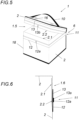
- FIG. 5 After the Figures 5 and 6 a bag 1 according to a second embodiment is shown.
- This bag 1 as a container for transporting goods has the shape of a box.
- a zipper 11 is used as the closure 7, behind which, seen from the outside 1.6 of the bag 1, the wall ends 2.1 and 2.2 of the bag wall 2 overlap, as is particularly evident in the Fig. 6 can be seen.
- vermiculite pillows and/or other insulating materials can be added to the box to resist a fire in bag 1 or to ensure safe transport of goods.
- the bag according to the invention can be particularly suitable as a charging bag and/or as a bag for the transport of dangerous goods, preferably batteries or goods containing batteries.
Landscapes
- Chemical & Material Sciences (AREA)
- Chemical Kinetics & Catalysis (AREA)
- Electrochemistry (AREA)
- General Chemical & Material Sciences (AREA)
- Engineering & Computer Science (AREA)
- Manufacturing & Machinery (AREA)
- Life Sciences & Earth Sciences (AREA)
- Biophysics (AREA)
- Ceramic Engineering (AREA)
- Purses, Travelling Bags, Baskets, Or Suitcases (AREA)
- Bag Frames (AREA)
Description
- Die Erfindung betrifft eine Tasche mit einer Taschenwand aus einem flexiblen Laminat, das einen Dämmschichtbildner aufweist, und mit einem die Taschenwand verschließbaren Verschluss.
- Feuerfeste Taschen für Mobiltelefone sind beispielsweise aus der
CN204796963U bekannt. Die Taschenwand derartiger Taschen weist hierzu ein Laminat aus verschiedensten Materialien auf, unter anderem auch eine Schicht aus einem Dämmschichtbildner, um damit einen Brand einzudämmen. Nachteilig sind derartige Taschen mit einem vielschichtigen Laminat als Taschenwand und so vergleichsweise wärmeisolierend. Dies erhöht insbesondere die Gefahr einer Überhitzung einer in der Tasche aufgenommen und zu ladenden Batterie. Außerdem sind derartige Laminate vergleichsweise aufwendig in der Herstellung und durch eine hohe Anzahl an aufeinanderfolgenden Schichten vergleichsweise unflexibel, was die Handhabbarkeit der Tasche erschwert. - Des Weiteren ist aus der
DE 20212 003810 U1 ein wärmeleitendes Verbundelement bekannt, umfassend wenigstens einen expandierten Graphit enthaltenden Formkörper sowie wenigstens ein auf wenigstens einer Seite des Formkörpers angeordnetes textiles Flächengebilde, wobei das wenigstens eine textile Flächengebilde mit dem Formkörper über einen anorganischen Klebstoff verbunden ist. Diese Vorrichtung ist zur Verwendung in einer Flächenkühlung oder in einer Flächenheizung vorgesehen. - Die Erfindung hat sich daher die Aufgabe gestellt, eine Tasche der eingangs geschilderten Art derart konstruktiv zu verändern, dass trotz standfestem Brandschutz der Tasche die Gefahr einer Überhitzung beim Laden der Batterie gering ist. Zudem soll die Tasche konstruktiv einfach aufgebaut und einfach zu handhaben sein.
- Die Erfindung löst die gestellte Aufgabe durch die Merkmale des Anspruchs 1.
- Weist das Laminat als Träger ein flexibles Gewebe auf, das mit dem Dämmschichtbildner beschichtet ist, kann eine vergleichsweise flexible und dünne Taschenwand geschaffen werden, die dennoch eine hohe Brandbeständigkeit aufweist. So kann nämlich das Gewebe bei einem Aufschäumen des Dämmschichtbildners diesem flexibel folgen und damit den Brand in der Tasche lokal einschließen. Dies zudem auch deutlich temperaturfest, wenn das Gewebe ein Glasfasergewebe ist. Hierzu kann beispielsweise auch der aufschäumende Dämmschichtbildner eine Basis auf Blähgraphit aufweisen.
- Neben der hohen Brandsicherheit der erfindungsgemäßen Tasche kann auch jenes Gewebe mit einem nicht aufgeschäumten Dämmschichtbildner eine hohe Wärmedurchlässigkeit aufweisen und damit auch eine Brandgefahr beispielsweise beim Laden vermeiden. Die erfindungsgemäße Tasche ist daher besonders als Behälter für Waren, vorzugsweise von Waren mit Batterien oder Batterien geeignet, insbesondere zum Transportieren derselbigen.
- Vorzugsweise ist die Tasche eine Ladetasche. Die Tasche kann auch jede beliebige Form aufweisen, beispielsweise die Form eines Etuis, die Form einer Box etc..
- Die Brandbeständigkeit kann noch weiter erhöht werden, wenn das Gewebe den Dämmschichtbildner auf der Innenseite der Tasche aufweist. Zudem kann mit dieser Innenlage des Dämmschichtbildners die Reaktionsgeschwindigkeit der Tasche zur Brandbekämpfung deutlich erhöht werden.
- Weist das Laminat auf der Innenseite der Tasche eine Folie auf, die den Dämmschichtbildner abdeckt, können die aufgenommenen elektrischen Geräte bzw.
- Batterien gegenüber Beschädigungen, wie beispielsweise gegenüber Kratzer, geschützt werden. Zudem kann diese Folie auch den Dämmschichtbildner gegenüber Abrieb bzw. Abtrag durch aufgenommene elektrische Geräte bzw. Batterien schützen, was die Standfestigkeit der Tasche weiter erhöhen kann.
- Vorzugsweise weist das Gewebe ein Flächengewicht von 50 bis 500 g/m2, insbesondere von 140 bis 250 g/m2, auf, um eine ausreichende Flexibilität und Festigkeit im Brandfall gewährleisten zu können.
- Als ausreichend zur Eindämmung von Bränden kann ermöglicht werden, wenn der Dämmschichtbildner ein Flächengewicht von mindestens 300 g/m2, insbesondere von mindestens 700 g/m2 aufweist.
- Vorzugsweise weist das Laminat ein Flächengewicht von maximal 4000 g/m2, insbesondere maximal 2000 g/m2, insbesondere maximal 1200 g/m2, auf, um trotz Brandbeständigkeit eine ausreichende flexible Außenwand für eine einfache Handhabung gewährleisten zu können.
- Eine ausreichende Flexibilität des Laminats kann erreicht werden, wenn das Laminat eine Dicke von 0,5 bis 5 mm aufweist.
- Ist das Laminat perforiert, kann dies zudem besonderen Einfluss auf die Kühlung einer beispielsweise zu ladenden Batterien nehmen und damit diese vor Überhitzung schützen. Im Brandfall verschließt der aufschäumende Dämmschichtbildner diese Perforierung, wodurch die Tasche trotz Perforation eine hohe Brandbeständigkeit aufweisen kann.
- Eine besonders auch im Brandfall standfeste Tasche kann geschaffen werden, wenn die Tasche an den Seitenkanten entlanglaufende Bänder, insbesondere Gurtbänder, aufweist, die das Laminat an der jeweiligen Seitenkante umfassen und mit dem Laminat vernäht sind. So können nämlich durch das mit dem Gewebe des Laminats vernähte Band vergleichsweise hohen Druckkräften des sich aufschäumenden Dämmschichtbildners widerstanden werden. Dies stellt zudem sicher, dass die Tasche sicher gegenüber einen Schaumaustritt ist.
- Konstruktive Einfachheit kann erreicht werden, wenn die Taschenwand von einem umgebogenen und damit den Taschenboden formenden Laminat ausgebildet wird.
- Hohen Temperaturen kann die Tasche standhalten, wenn die Naht oder generell alle Nähte der Tasche 1 ein brandbeständiges Garn, insbesondere Kevlargarn, aufweist.
- Die Gefahr eines Überschlags eines Brands aus der Tasche heraus kann verringert werden, wenn der Verschluss zwei zum Verschließen der Taschenwand zusammenwirkende Leisten, insbesondere Magnetleisten oder Federstahlleisten, aufweist, die am Laminat befestigt sind.
- Vorzugsweise weist die Tasche eine Trageschlaufe auf, um auch im Brandfall die Tasche sicher beispielhaft zu einem sicheren Ort transportieren zu können.
- Besteht die Trageschlaufe aus einem Gewebeband, insbesondere Gurtband, kann eine hohe Standfestigkeit auch bei vergleichsweise hohen Temperaturen in der Tasche beispielsweise durch einen Brand ausgelöst, getragen werden.
- Vorzugsweise ist die Trageschlaufe im Bereich der Taschenöffnung an der Tasche befestigt, um beim Tragen die aufgenommenen Teile, beispielsweise Mobiltelefone, vor einem Herausfallen zu sichern.
- Eine besonders im Brandfall standfeste Tasche kann geschaffen werden, wenn die Taschenwand im Bereich der Taschenöffnung zwei gegenüberliegende Wandenden ausbildet, die sich im Bereich der Taschenöffnung überlappen.
- Vorstellbar ist weiter, dass der Verschluss ein Reißverschluss oder ein anderes auf Formschluss beruhendes Verschlussmittel aufweist, die Brandbeständigkeit der Tasche zu erhöhen.
- Die Konstruktion der Tasche kann vereinfacht werden, wenn der Reißverschluss ein erstes Seitenteil mit ersten Schließgliedern und ein zweites Seitenteil mit zweiten Schließgliedern aufweist, wobei die Seitenteile an der Taschenwand, insbesondere über je eine erste Naht, befestigt und insbesondere an der Außenseite der Tasche vorgesehen sind.
- Hierzu kann beispielsweise sich das erste Wandende, an dem das erste Seitenteil befestigt ist, zumindest über die zweiten Schließglieder des zweiten Seitenteils erstrecken.
- Vorzugsweise erstreckt sich das zweite Wandende, an dem das zweite Seitenteil befestigt ist, höchstens bis zu den zweiten Schließgliedern.
- Ist zumindest ein Seitenteil über eine zweite Naht an der Taschenwand befestigt, wobei die Naht zu den Schließgliedern dieses Seitenteils einen Abstand kleiner der Schließgliederbreite des Reißverschlusses aufweist, kann dies eine Überlappung der Wandenden standfest sicherstellen.
- Weist die Taschenwand eine Kabeldurchführung auf, kann dies die Handhabung der Tasche erleichtern. Vorzugsweise ist die Kabeldurchführung auch als Überdruckventil ausgebildet.
- In den Figuren ist beispielsweise der Erfindungsgegenstand anhand mehrerer Ausführungsbeispiele näher dargestellt. Es zeigen
- Fig. 1
- eine teilweise aufgerisse Seitensicht auf eine Tasche nach einem ersten Ausführungsbeispiel,
- Fig. 2
- eine Schnittansicht der
Fig. 1 , - Fig. 3
- eine dreidimensionale Ansicht auf die Tasche nach
Fig. 1 mit einem anderen Verschluss, - Fig. 4
- eine schematisch dargestellte Schnittansicht auf den Verschluss der Tasche nach
Fig. 3 , - Fig. 5
- eine Ansicht auf eine gegenüber der
Fig. 1 größer ausgeführten Tasche nach einem weiteren Ausführungsbeispiel und - Fig. 6
- eine schematisch dargestellte Schnittansicht auf den Verschluss der Tasche nach
Fig. 5 . - Nach den
Figuren 1 bis 4 wird eine Tasche 1 nach einem ersten Ausführungsbeispiel gezeigt. Diese Tasche 1 weist eine Taschenwand 2 auf, die eine Aufnahme 3 für beispielsweise ein Mobiltelefon 4 (als ein Beispiel für eine Waren mit einer Batterie) ausbildet. Das Mobiltelefon 4 wird optional über eine induktive Ladestation 5 durch die Taschenwand 2 hindurchgehend induktiv geladen. In diesem Fall ist die Tasche 1 eine Ladetasche 17. - Über einen Verschluss 6 der Tasche 1 kann ein Zugang zur Aufnahme 3 geschaffen werden bzw. kann damit die Tasche 1 geöffnet oder verschlossen werden. Die Taschenwand 2 besteht aus einem flexiblen Laminat 7, das einen Dämmschichtbildner 7.1 aufweist, wie dies nach
Fig. 2 erkannt werden kann. - Erfindungsgemäß wird bei hoher Flexibilität der Taschenwand 2 eine hohe Brandbeständigkeit erreicht, indem das Laminat 7 als Träger ein flexibles Gewebe 7.2, nämlich Glasfasergewebe, aufweist, das mit dem Dämmschichtbildner 7.1 beschichtet ist und damit direkt an das flexible Gewebe 7.2 anschließt.
- Wie in der
Fig. 2 zu erkennen, weist das Gewebe 7.2 den Dämmschichtbildner 7.1 auf der Innenseite 1.1 der Tasche 1 auf, wodurch ein Brand des Mobiltelefons 4 reaktionsschnell vom Dämmschichtbildner 7.1 eingedämmt wird. Dies, weil der Dämmschichtbildner 7.1 aufschäumend und auf Basis von Blähgraphit ist. - Das Laminat 7 weist zudem auf der Innenseite 1.1 der Tasche 1 eine Folie 7.3 auf, die den Dämmschichtbildner 7.1 vollständig abdeckt. Dies schützt den Dämmschichtbildner 7.1 gegenüber Abrieb und erleichtert auch ein Einschieben eines Mobiltelefons 4 in die Tasche 1.
- Vorzugsweise weist die Außenseite 1.6 der Tasche 1 keinen Dämmschichtbildner 7.1 auf bzw. ist das Gewebe 7.2 auf dieser Seite frei vom Dämmschichtbildner 7.1.
- Das Gewebe 7.2 weist ein Flächengewicht von 50 bis 500 g/m2, insbesondere von 140 bis 250 g/m2, auf. Der Dämmschichtbildner 7.1 weist ein Flächengewicht von mindestens 300 g/m2, insbesondere von mindestens 700 g/m2 auf. Das Laminat 7 weist ein Flächengewicht von maximal 2500 g/m2, insbesondere maximal 950 g/m2, auf. Zudem weist das Laminat 7 eine Dicke von 0,5 bis 5 mm auf.
- Zudem ist das Laminat 7 perforiert, indem in vorzugsweise regelmäßigen Abständen Löcher 7.4 im Laminat 7 vorgesehen sind.
- Der Verschluss 6 besteht nach
Fig. 1 aus zwei zum Verschließen der Taschenwand 2 zusammenwirkende Leisten 6.1, 6.2, nämlich Magnetleisten oder Federstahlleisten. Diese Leisten 6.1, 6.2 können in Laschen eingebettet sein, was das Laminat 7 ausbildet - nachFig. 1 sind die Leisten 6.1, 6.2 mit dem Laminat 7 über eine Naht 8 vernäht dargestellt. - Die Tasche 1 ist an den Seitenkanten 1.2, 1.3 verstärkt ausgeführt. Dies mit an den Seitenkanten 1.2, 1.3 entlanglaufendem Gewebeband 9.1, 9.2, nämlich vorzugsweise Gurtbändern. Die Gewebebänder sind um die Seitenkanten 1.2, 1.3 umgeschlagen bzw. umfassen diese und sind mit dem Laminat über eine Naht 8, nämlich in Form eines Geradstichs, vernäht. Für diese Naht 8 oder generell für die anderen Nähte 14, 15 der Tasche 1 wird ein brandbeständiges Garn, nämlich vorzugsweise Kevlargarn, verwendet, was einen standfesten Verbund zwischen Gewebeband 9.1 bzw. 9.2 und flexiblen Gewebe 7.2 des Laminats 7 schafft.
- Die Tasche 1 ist auch vergleichsweise einfach konstruktiv aufgebaut. So wird die Taschenwand 2 von einem umgebogenen und damit den Taschenboden 1.4 formenden Laminat 7 ausgebildet. An den Seitenkanten 1.2, 1.3 sind die aufeinanderliegenden Halbseiten des Laminats 7 mit dem jeweiligen Gewebeband 9.1, 9.2 vernäht.
- Auf der dem Taschenboden 1.4 gegenüberliegenden Seite ist die Taschenöffnung 1.5 mit dem Verschluss 6 vorgesehen. Die Aufnahme 3 der Tasche 1 ist nur über diese Taschenöffnung 1.5 zugänglich. Im Allgemeinen wird erwähnt, dass die Tasche 1 die Form eines Etuis aufweisen kann.
- Wie der
Fig. 1 zudem zu entnehmen, weist die Tasche 1 eine Trageschlaufe 10 auf. Die Trageschlaufe 10 besteht aus einem Gewebeband 9.3, nämlich Gurtband. Damit kann die Tasche auch im Brandfall standfest und sicher abgetragen werden. Vorzugsweise ist die Trageschlaufe 10 im Bereich der Taschenöffnung 1.5 an der Tasche 1 befestigt, um im Brandfall dennoch sicher die Tasche tragen zu können. Zudem kann ein Herausfallen beispielsweise der aufgenommenen brennenden Batterie bzw. des Telefons etc. damit standfest vermieden werden. - Vorstellbar ist auch, dass ein Gewebeband 9.1 bzw. 9.2 an einer Seitenkante 1.2 bzw. 1.3 in das Gewebeband 9.2 der Trageschlaufe 10 übergeht.
- Vorzugsweise weist das Gewebe 7.2 ein Flächengewicht von 200 g/m2, der Dämmschichtbildner 7.1 ein Flächengewicht von 750g/m2 und das Laminat 7 mit Folie ein Flächengewicht von ca. 950g/m2. Das Laminat 7 ist 0,7 mm dick. Dies reicht aus, herkömmliche Mobiltelefone in der Tasche 1 sicher aufzunehmen. Beispielsweise hat sich ein Flächengewicht von 500 - 800 g/m2 für Batterien bis 5000mAh als ausreichend herausgestellt. Beispielsweise hat sich ein Flächengewicht von 800 - 1400 g/m2 für Batterien von 5000 bis 10000 mAh als ausreichend herausgestellt. Beispielsweise hat sich ein Flächengewicht von 1400 - 2400 g/m2 für Batterien von ab 10000 mAh als ausreichend herausgestellt.
- Die Tasche 1 nach
Fig. 3 weist einen anderen Verschluss 6 auf, nämlich einen Reißverschluss 11. Der Reißverschluss 11 weist ein erstes Seitenteil 12 erste Schließglieder 12a, nämlich Spiralen, und ein zweites Seitenteil 13 zweite Schließglieder 13a, nämlich auch Spiralen, auf. Die Seitenteile 12 und 13 sind über je eine erste Naht 14 mit der Taschenwand 2 fest verbunden. Diese Nähte 14 befinden sich randseitig an den Seitenteilen 12, 13. Außerdem sind die Seitenteile 12, 13 an der Außenseite 1.6 der Tasche 1 vorgesehen, wie inFig. 4 zu erkennen. - Die Taschenwand 2 bildet im Bereich der Taschenöffnung 1.5 zwei gegenüberliegende Wandenden 2.1, 2.2 aus, die sich im Bereich der Taschenöffnung 1.5 überlappen. Hierfür erstreckt sich das erste Wandende 2.1, an dem das erste Seitenteil 12 befestigt ist, über die zweiten Schließglieder 13a des zweiten Seitenteils 13, wie in
Fig. 4 zu erkennen. - Das zweite Wandende 2.2, an dem das zweite Seitenteil 13 befestigt ist, erstreckt sich bis zu den zweiten Schließgliedern 13a.
- Zudem ist das zweite Seitenteil 13 mit einer zweiten Naht 15 an der Taschenwand 2 befestigt. Diese zweite Naht 15 weist zu den Schließgliedern 13a des zweiten Seitenteils 13 einen Abstand A kleiner der Schließgliederbreite B des Reißverschlusses 11 auf. Damit kann eine richtige Überlappung der Wandenden 2.1 und 2.2 sichergestellt werden, indem damit stets das Wandende 2.1 vom Reißverschluss 11 aus gesehen unterhalb des Wandendes 2.2 liegt.
- Zudem weist die Tasche 1 nach
Fig. 4 eine Kabeldurchführung 16 auf. Die Kabeldurchführung kann beispielsweise durch einen Schnitt in der Taschenwand 2 und einen über den Schnitt vorgehenden vorzugsweise runden Patch, der mit der Taschenwand 2 umlaufend vernäht ist. Über eine beispielsweise x-förmige Öffnung im Patch wird so die Innenseite 1.1 der Tasche 1 zugänglich. Im Brandfall verschließt der Dämmschichtbildner 7.1 den Schnitt in der Taschenwand 2 unterhalb des Patchs, sodass die Kabeldurchführung 16 dicht verschlossen wird. - Nach den
Figuren 5 und 6 wird eine Tasche 1 nach einem zweiten Ausführungsbeispiel gezeigt. Diese Tasche 1 als Behälter zum Transport von Waren, weist die Form einer Box auf. Auch hier wird als Verschluss 7 ein Reißverschluss 11 verwendet, hinter dem, vom der Außenseite 1.6 der Tasche 1 gesehen, die Wandende 2.1 und 2.2 der Taschenwand 2 überlappen, wie dies insbesondere in derFig. 6 zu erkennen ist. In die Box kann beispielsweise noch Vermiculite-Kissen und/oder andere Dämmschichtbildner zugegeben werden, einem Brand in der Tasche 1 zu widerstehen oder auch für einen sicheren Transport von Waren sorgen. - Damit kann sich die erfindungsgemäße Tasche insbesondere als Ladetasche und/oder als Tasche zum Gefahrguttransport vorzugsweise von Batterien oder Waren mit Batterien eignen.
Claims (15)
- Tasche mit einer Taschenwand (2) aus einem flexiblen Laminat (7), das einen Dämmschichtbildner (7.1) aufweist, und mit einem eine Taschenöffnung (1.5) der Tasche (1) verschließbaren Verschluss (6), dadurch gekennzeichnet, dass das Laminat (7) als Träger ein flexibles Gewebe (7.2), insbesondere Glasfasergewebe, aufweist, das mit dem Dämmschichtbildner (7.1) beschichtet ist und wobei der Dämmschichtbildner (7.1) aufschäumend und auf Basis von Blähgraphit ist.
- Tasche nach Anspruch 1, dadurch gekennzeichnet, dass das Gewebe (7.2) den Dämmschichtbildner (7.1) auf der Innenseite (1.1) der Tasche (1) aufweist.
- Tasche nach Anspruch 2, dadurch gekennzeichnet, dass das Laminat (7) auf der Innenseite (1.1) der Tasche (1) eine Folie aufweist, die den Dämmschichtbildner (7.1) abdeckt.
- Tasche nach einem der Ansprüche 1 bis 3, dadurch gekennzeichnet, dass das Gewebe (7.2) ein Flächengewicht von 50 bis 500 g/m2, insbesondere von 140 bis 250 g/m2, aufweist und/oder der Dämmschichtbildner (7.1) ein Flächengewicht von mindestens 300 g/m2, insbesondere von mindestens 700 g/m2, aufweist.
- Tasche nach Anspruch 4, dadurch gekennzeichnet, dass das Laminat (7) ein Flächengewicht von maximal 4000 g/m2, insbesondere maximal 2000 g/m2, insbesondere maximal 1200 g/m2, aufweist.
- Tasche nach einem der Ansprüche 1 bis 5, dadurch gekennzeichnet, dass das Laminat (7) eine Dicke von 0,5 bis 5 mm aufweist und/oder das Laminat (7) perforiert ist.
- Tasche nach einem der Ansprüche 1 bis 6, dadurch gekennzeichnet, dass die Tasche (1) ein an den Seitenkanten (1.2, 1.3) entlanglaufendes Gewebeband (9.1, 9.2), insbesondere Gurtbänder, aufweist, die das Laminat (7) an der jeweiligen Seitenkante (1.2, 1.3) umfassen und mit dem Laminat (7) vernähtist, wobei die Taschenwand (2) insbesondere von einem umgebogenen und damit den Taschenboden (1.4) formenden Laminat (7) ausgebildet wird, wobei die Naht (8) insbesondere ein brandbeständiges Garn (8.1), insbesondere Kevlargarn, aufweist.
- Tasche nach einem der Ansprüche 1 bis 7, dadurch gekennzeichnet, dass die Tasche (1) eine Trageschlaufe (10) aufweist, wobei die Trageschlaufe (10) insbesondere aus einem Gewebeband (9.3), insbesondere Gurtband, besteht, wobei die Trageschlaufe (10) insbesondere im Bereich der Taschenöffnung (1.5) an der Tasche (1) befestigt ist.
- Tasche nach einem der Ansprüche 1 bis 8, dass die Taschenwand (2) im Bereich der Taschenöffnung (1.5) zwei gegenüberliegende Wandenden (2.1, 2.2) ausbildet, die sich im Bereich der Taschenöffnung (1.5) überlappen.
- Tasche nach einem der Ansprüche 1 bis 9, dadurch gekennzeichnet, dass der Verschluss (6) ein Reißverschluss (11) oder ein anderes auf Formschluss beruhendes Verschlussmittel aufweist.
- Tasche nach Anspruch 10, dadurch gekennzeichnet, dass der Reißverschluss (11) ein erstes Seitenteil (12) mit ersten Schließgliedern (12a) und ein zweites Seitenteil (13) mit zweiten Schließgliedern (13a) aufweist, wobei die Seitenteile (12, 13) an der Taschenwand (2), insbesondere über je eine erste Naht (14), befestigt und insbesondere an der Außenseite (1.6) der Tasche (1) vorgesehen sind.
- Tasche nach Anspruch 11, dadurch gekennzeichnet, dass das erste Wandende (2.1), an dem das erste Seitenteil (12) befestigt ist, sich zumindest über die zweiten Schließglieder (13a) des zweiten Seitenteils (13) erstreckt.
- Tasche nach einem der Ansprüche 11 bis 12, dadurch gekennzeichnet, dass das zweite Wandende (2.2), an dem das zweite Seitenteil (13) befestigt ist, sich höchstens bis zu den zweiten Schließgliedern (13a) erstreckt.
- Tasche nach einem der Ansprüche 11 bis 13, dadurch gekennzeichnet, dass zumindest ein Seitenteil (13) über eine zweite Naht (15) an der Taschenwand (2) befestigt ist, wobei die Naht (15) zu den Schließgliedern (13a) dieses Seitenteils (13) einen Abstand (A) kleiner der Schließgliederbreite (B) des Reißverschlusses (11) aufweist.
- Verwendung einer Tasche (1) nach einem der Ansprüche 1 bis 14 als Ladetasche und/oder als Gefahrguttransporttasche vorzugsweise von Batterien oder Waren mit Batterien.
Applications Claiming Priority (2)
| Application Number | Priority Date | Filing Date | Title |
|---|---|---|---|
| AT503622019 | 2019-04-18 | ||
| PCT/AT2020/060159 WO2020210857A1 (de) | 2019-04-18 | 2020-04-20 | Tasche |
Publications (3)
| Publication Number | Publication Date |
|---|---|
| EP3956136A1 EP3956136A1 (de) | 2022-02-23 |
| EP3956136B1 true EP3956136B1 (de) | 2024-12-11 |
| EP3956136C0 EP3956136C0 (de) | 2024-12-11 |
Family
ID=70856968
Family Applications (1)
| Application Number | Title | Priority Date | Filing Date |
|---|---|---|---|
| EP20728382.1A Active EP3956136B1 (de) | 2019-04-18 | 2020-04-20 | Tasche |
Country Status (2)
| Country | Link |
|---|---|
| EP (1) | EP3956136B1 (de) |
| WO (1) | WO2020210857A1 (de) |
Families Citing this family (3)
| Publication number | Priority date | Publication date | Assignee | Title |
|---|---|---|---|---|
| DE102021111704A1 (de) * | 2021-05-05 | 2022-11-10 | JUTEC Hitzeschutz und Isoliertechnik GmbH | Schutztasche für einen Akku |
| GB202312094D0 (en) * | 2023-08-08 | 2023-09-20 | Envirograf Ltd | Vehicle battery enclosure |
| WO2025032332A1 (en) * | 2023-08-08 | 2025-02-13 | Envirograf Ltd | Fire-proofed cover for battery units of vehicles |
Family Cites Families (5)
| Publication number | Priority date | Publication date | Assignee | Title |
|---|---|---|---|---|
| US10364527B2 (en) * | 2007-10-24 | 2019-07-30 | W. L. Gore & Associates, Inc. | Burn protective materials |
| DE102012204124A1 (de) * | 2012-03-15 | 2013-09-19 | Sgl Carbon Se | Wärmeleitendes Verbundelement auf Basis von expandiertem Graphit |
| CN204796963U (zh) | 2015-06-26 | 2015-11-25 | 苏州佰林特包装材料有限公司 | 手机保护袋 |
| CN205646008U (zh) * | 2016-05-26 | 2016-10-12 | 宁德时代新能源科技股份有限公司 | 电池模组 |
| EP3263793A1 (de) * | 2016-06-28 | 2018-01-03 | HILTI Aktiengesellschaft | Brandschutzelement mit einem trägergewebe |
-
2020
- 2020-04-20 EP EP20728382.1A patent/EP3956136B1/de active Active
- 2020-04-20 WO PCT/AT2020/060159 patent/WO2020210857A1/de not_active Ceased
Also Published As
| Publication number | Publication date |
|---|---|
| WO2020210857A1 (de) | 2020-10-22 |
| EP3956136A1 (de) | 2022-02-23 |
| WO2020210857A8 (de) | 2021-04-08 |
| EP3956136C0 (de) | 2024-12-11 |
Similar Documents
| Publication | Publication Date | Title |
|---|---|---|
| EP3956136B1 (de) | Tasche | |
| US20170343320A1 (en) | Vest having releasable components | |
| DE60130712T2 (de) | Tasche zum Aufbewahren von Werkzeugen | |
| DE202020101070U1 (de) | Schutzschild | |
| DE858948C (de) | Verpackung fuer stossempfindliche Gegenstaende, insbesondere Sprengladungszuender | |
| DE202004020643U1 (de) | Personentragbares Behältnis, insbesondere Rucksack | |
| US2183113A (en) | Fire mat | |
| DE20012075U1 (de) | Bekleidungsstück, insbesondere Oberbekleidungsstück | |
| DE102014221082A1 (de) | Mobilfunkgerätebehälter und Verfahren zum Herstellen eines Mobilfunkgerätebehälters | |
| CN108078101A (zh) | 一种防割、防砍、防刺、防水、防火、防爆的手提包 | |
| DE102007043577A1 (de) | Multifunktionsschlinge | |
| US20130126567A1 (en) | Rescue equipment bag | |
| EP3111159B1 (de) | Verknüpfte runde tragtasche | |
| CN210845035U (zh) | 一种防坠落装置 | |
| DE10340180B4 (de) | Abriebschutzvorrichtung | |
| DE202008006594U1 (de) | Feuerfeste Tasche | |
| EP1982615A1 (de) | Tragevorrichtung für am Körper zu tragende Gegenstände | |
| WO2005065481A1 (de) | Schulterhalfter zum von tragen von wertgegenständen | |
| EP2798972A1 (de) | Taschenanordnung | |
| DE202018005273U1 (de) | Hüftgurt mit Aufladefunktion und auf dem Rücken getragener Tragebehälter, wie z.B. Rucksack oder Schulranzen | |
| EP1946660B1 (de) | Wendbarer Schutzhandschuh aus einem Metallringgeflecht | |
| EP3791128A1 (de) | Gehäuse für ein werkzeug | |
| EP2899806A1 (de) | Rucksack mit einem Suchgerät | |
| DE202008008858U1 (de) | Hüfttaschenanordnung | |
| DE202021106124U1 (de) | Brandschutzverpackung |
Legal Events
| Date | Code | Title | Description |
|---|---|---|---|
| STAA | Information on the status of an ep patent application or granted ep patent |
Free format text: STATUS: UNKNOWN |
|
| STAA | Information on the status of an ep patent application or granted ep patent |
Free format text: STATUS: THE INTERNATIONAL PUBLICATION HAS BEEN MADE |
|
| PUAI | Public reference made under article 153(3) epc to a published international application that has entered the european phase |
Free format text: ORIGINAL CODE: 0009012 |
|
| STAA | Information on the status of an ep patent application or granted ep patent |
Free format text: STATUS: REQUEST FOR EXAMINATION WAS MADE |
|
| 17P | Request for examination filed |
Effective date: 20211118 |
|
| AK | Designated contracting states |
Kind code of ref document: A1 Designated state(s): AL AT BE BG CH CY CZ DE DK EE ES FI FR GB GR HR HU IE IS IT LI LT LU LV MC MK MT NL NO PL PT RO RS SE SI SK SM TR |
|
| DAV | Request for validation of the european patent (deleted) | ||
| DAX | Request for extension of the european patent (deleted) | ||
| STAA | Information on the status of an ep patent application or granted ep patent |
Free format text: STATUS: EXAMINATION IS IN PROGRESS |
|
| 17Q | First examination report despatched |
Effective date: 20230111 |
|
| GRAP | Despatch of communication of intention to grant a patent |
Free format text: ORIGINAL CODE: EPIDOSNIGR1 |
|
| STAA | Information on the status of an ep patent application or granted ep patent |
Free format text: STATUS: GRANT OF PATENT IS INTENDED |
|
| RIC1 | Information provided on ipc code assigned before grant |
Ipc: H01M 10/65 20140101ALI20231207BHEP Ipc: H01M 10/613 20140101ALI20231207BHEP Ipc: B32B 9/00 20060101ALI20231207BHEP Ipc: B32B 5/24 20060101ALI20231207BHEP Ipc: B32B 5/18 20060101ALI20231207BHEP Ipc: B32B 5/02 20060101AFI20231207BHEP |
|
| INTG | Intention to grant announced |
Effective date: 20231220 |
|
| GRAS | Grant fee paid |
Free format text: ORIGINAL CODE: EPIDOSNIGR3 |
|
| RAP1 | Party data changed (applicant data changed or rights of an application transferred) |
Owner name: VEIGL, MICHAEL FRIEDHELM |
|
| GRAA | (expected) grant |
Free format text: ORIGINAL CODE: 0009210 |
|
| STAA | Information on the status of an ep patent application or granted ep patent |
Free format text: STATUS: THE PATENT HAS BEEN GRANTED |
|
| RAP1 | Party data changed (applicant data changed or rights of an application transferred) |
Owner name: GENIUS PATENTVERWERTUNG GMBH & CO. KG Owner name: VEIGL, MICHAEL FRIEDHELM |
|
| AK | Designated contracting states |
Kind code of ref document: B1 Designated state(s): AL AT BE BG CH CY CZ DE DK EE ES FI FR GB GR HR HU IE IS IT LI LT LU LV MC MK MT NL NO PL PT RO RS SE SI SK SM TR |
|
| REG | Reference to a national code |
Ref country code: GB Ref legal event code: FG4D Free format text: NOT ENGLISH |
|
| REG | Reference to a national code |
Ref country code: CH Ref legal event code: EP |
|
| REG | Reference to a national code |
Ref country code: IE Ref legal event code: FG4D Free format text: LANGUAGE OF EP DOCUMENT: GERMAN |
|
| REG | Reference to a national code |
Ref country code: DE Ref legal event code: R096 Ref document number: 502020009945 Country of ref document: DE |
|
| U01 | Request for unitary effect filed |
Effective date: 20250110 |
|
| U07 | Unitary effect registered |
Designated state(s): AT BE BG DE DK EE FI FR IT LT LU LV MT NL PT RO SE SI Effective date: 20250117 |
|
| PG25 | Lapsed in a contracting state [announced via postgrant information from national office to epo] |
Ref country code: HR Free format text: LAPSE BECAUSE OF FAILURE TO SUBMIT A TRANSLATION OF THE DESCRIPTION OR TO PAY THE FEE WITHIN THE PRESCRIBED TIME-LIMIT Effective date: 20241211 |
|
| PG25 | Lapsed in a contracting state [announced via postgrant information from national office to epo] |
Ref country code: ES Free format text: LAPSE BECAUSE OF FAILURE TO SUBMIT A TRANSLATION OF THE DESCRIPTION OR TO PAY THE FEE WITHIN THE PRESCRIBED TIME-LIMIT Effective date: 20241211 |
|
| PG25 | Lapsed in a contracting state [announced via postgrant information from national office to epo] |
Ref country code: NO Free format text: LAPSE BECAUSE OF FAILURE TO SUBMIT A TRANSLATION OF THE DESCRIPTION OR TO PAY THE FEE WITHIN THE PRESCRIBED TIME-LIMIT Effective date: 20250311 |
|
| PG25 | Lapsed in a contracting state [announced via postgrant information from national office to epo] |
Ref country code: GR Free format text: LAPSE BECAUSE OF FAILURE TO SUBMIT A TRANSLATION OF THE DESCRIPTION OR TO PAY THE FEE WITHIN THE PRESCRIBED TIME-LIMIT Effective date: 20250312 |
|
| PG25 | Lapsed in a contracting state [announced via postgrant information from national office to epo] |
Ref country code: RS Free format text: LAPSE BECAUSE OF FAILURE TO SUBMIT A TRANSLATION OF THE DESCRIPTION OR TO PAY THE FEE WITHIN THE PRESCRIBED TIME-LIMIT Effective date: 20250311 |
|
| U20 | Renewal fee for the european patent with unitary effect paid |
Year of fee payment: 6 Effective date: 20250417 |
|
| PG25 | Lapsed in a contracting state [announced via postgrant information from national office to epo] |
Ref country code: SM Free format text: LAPSE BECAUSE OF FAILURE TO SUBMIT A TRANSLATION OF THE DESCRIPTION OR TO PAY THE FEE WITHIN THE PRESCRIBED TIME-LIMIT Effective date: 20241211 |
|
| PG25 | Lapsed in a contracting state [announced via postgrant information from national office to epo] |
Ref country code: PL Free format text: LAPSE BECAUSE OF FAILURE TO SUBMIT A TRANSLATION OF THE DESCRIPTION OR TO PAY THE FEE WITHIN THE PRESCRIBED TIME-LIMIT Effective date: 20241211 |
|
| PG25 | Lapsed in a contracting state [announced via postgrant information from national office to epo] |
Ref country code: IS Free format text: LAPSE BECAUSE OF FAILURE TO SUBMIT A TRANSLATION OF THE DESCRIPTION OR TO PAY THE FEE WITHIN THE PRESCRIBED TIME-LIMIT Effective date: 20250411 |
|
| PG25 | Lapsed in a contracting state [announced via postgrant information from national office to epo] |
Ref country code: SK Free format text: LAPSE BECAUSE OF FAILURE TO SUBMIT A TRANSLATION OF THE DESCRIPTION OR TO PAY THE FEE WITHIN THE PRESCRIBED TIME-LIMIT Effective date: 20241211 |
|
| PG25 | Lapsed in a contracting state [announced via postgrant information from national office to epo] |
Ref country code: CZ Free format text: LAPSE BECAUSE OF FAILURE TO SUBMIT A TRANSLATION OF THE DESCRIPTION OR TO PAY THE FEE WITHIN THE PRESCRIBED TIME-LIMIT Effective date: 20241211 |
|
| PLBE | No opposition filed within time limit |
Free format text: ORIGINAL CODE: 0009261 |
|
| STAA | Information on the status of an ep patent application or granted ep patent |
Free format text: STATUS: NO OPPOSITION FILED WITHIN TIME LIMIT |
|
| REG | Reference to a national code |
Ref country code: CH Ref legal event code: L10 Free format text: ST27 STATUS EVENT CODE: U-0-0-L10-L00 (AS PROVIDED BY THE NATIONAL OFFICE) Effective date: 20251022 |
|
| 26N | No opposition filed |
Effective date: 20250912 |
|
| REG | Reference to a national code |
Ref country code: CH Ref legal event code: H13 Free format text: ST27 STATUS EVENT CODE: U-0-0-H10-H13 (AS PROVIDED BY THE NATIONAL OFFICE) Effective date: 20251125 |