EP3955048B1 - Anordnung zur erzeugung eines bessel-strahls - Google Patents
Anordnung zur erzeugung eines bessel-strahls Download PDFInfo
- Publication number
- EP3955048B1 EP3955048B1 EP21195202.3A EP21195202A EP3955048B1 EP 3955048 B1 EP3955048 B1 EP 3955048B1 EP 21195202 A EP21195202 A EP 21195202A EP 3955048 B1 EP3955048 B1 EP 3955048B1
- Authority
- EP
- European Patent Office
- Prior art keywords
- lens
- forming element
- arrangement according
- bessel
- fourier
- Prior art date
- Legal status (The legal status is an assumption and is not a legal conclusion. Google has not performed a legal analysis and makes no representation as to the accuracy of the status listed.)
- Active
Links
Images


Classifications
-
- G—PHYSICS
- G02—OPTICS
- G02B—OPTICAL ELEMENTS, SYSTEMS OR APPARATUS
- G02B27/00—Optical systems or apparatus not provided for by any of the groups G02B1/00 - G02B26/00, G02B30/00
- G02B27/09—Beam shaping, e.g. changing the cross-sectional area, not otherwise provided for
- G02B27/0927—Systems for changing the beam intensity distribution, e.g. Gaussian to top-hat
-
- G—PHYSICS
- G02—OPTICS
- G02B—OPTICAL ELEMENTS, SYSTEMS OR APPARATUS
- G02B27/00—Optical systems or apparatus not provided for by any of the groups G02B1/00 - G02B26/00, G02B30/00
- G02B27/09—Beam shaping, e.g. changing the cross-sectional area, not otherwise provided for
- G02B27/0905—Dividing and/or superposing multiple light beams
-
- G—PHYSICS
- G02—OPTICS
- G02B—OPTICAL ELEMENTS, SYSTEMS OR APPARATUS
- G02B27/00—Optical systems or apparatus not provided for by any of the groups G02B1/00 - G02B26/00, G02B30/00
- G02B27/09—Beam shaping, e.g. changing the cross-sectional area, not otherwise provided for
- G02B27/0938—Using specific optical elements
- G02B27/095—Refractive optical elements
- G02B27/0955—Lenses
-
- G—PHYSICS
- G02—OPTICS
- G02B—OPTICAL ELEMENTS, SYSTEMS OR APPARATUS
- G02B27/00—Optical systems or apparatus not provided for by any of the groups G02B1/00 - G02B26/00, G02B30/00
- G02B27/09—Beam shaping, e.g. changing the cross-sectional area, not otherwise provided for
- G02B27/0938—Using specific optical elements
- G02B27/095—Refractive optical elements
- G02B27/0955—Lenses
- G02B27/0961—Lens arrays
-
- G—PHYSICS
- G02—OPTICS
- G02B—OPTICAL ELEMENTS, SYSTEMS OR APPARATUS
- G02B5/00—Optical elements other than lenses
- G02B5/001—Axicons, waxicons, reflaxicons
Definitions
- the invention relates to an arrangement for generating a Bessel beam, with a beam-forming element which transforms a beam incident as a plane electromagnetic wave into a Bessel beam, wherein the beam-forming element comprises at least one ring lens and a Fourier optic.
- a Bessel beam is a special form of electromagnetic waves, in particular light rays, whose essential property is that they are non-diffracting; the beam profile is preserved during propagation.
- Bessel-Gaussian beam is often used for a Bessel beam that is actually generated, since an ideal Bessel beam cannot be generated for physical reasons. This distinction is omitted below.
- the invention relates to Bessel beams that are generated under real conditions, i.e. non-ideal Bessel beams.
- a beam-forming element to generate a Bessel beam, which transforms a beam that is incident as a plane electromagnetic wave into a Bessel beam. Since a Bessel beam is a conical superposition of plane waves, the beam-forming elements used in the prior art are mainly conical lenses, so-called axicons (cf. J. Arlt and K. Dholakia: "Generation of high-order Bessel beams by use of an axicon", Optics Communications 177.1-6, 2000, pp. 297-301 ). These have a high efficiency but are quite inflexible when it comes to combining multiple beams. In addition, axicons are difficult to manufacture in good quality due to the central tip, are expensive and are also susceptible to damage.
- Another arrangement for generating Bessel beams in a Kepler configuration is known from the GB 2 256 338 A known.
- SLMs spatial light modulators
- the Fourier optics is a Fourier lens, wherein the focal planes of the ring lens and the Fourier lens coincide, so that the ring lens and the Fourier lens form a Galilean configuration, wherein the ring lens is formed integrally with the Fourier lens, as defined in claim 1.
- the inventive generation of the Bessel beam is based on the Fourier principle.
- a Bessel beam is, as already mentioned above, a conical superposition of plane waves. Accordingly, the solid angle spectrum of the Bessel beam is given by a sharp, circular ring.
- the Bessel beam results from spatial Fourier transformation of such a ring.
- a ring lens is used to generate ring-shaped radiation.
- the ring lens has a ring-shaped, curved surface which, viewed in cross-section, corresponds to a cylindrical lens that is closed in on itself, e.g. to form a circle.
- the ring lens produces a sharp ring-shaped beam profile in its focal plane.
- the ring lens according to the invention can, but does not necessarily have to, be circular. Different ring shapes, e.g. elliptical shapes, are also conceivable in order to produce corresponding variants of Bessel beams.
- the Fourier transformation is carried out by a Fourier lens, i.e. any converging lens which, arranged downstream of the ring lens, is used as a Fourier optics.
- the beam-forming element of the arrangement according to the invention is particularly compact in that the ring lens is formed in one piece with the Fourier lens.
- the beam-forming element can have a concave ring lens on the surface facing the incident plane wave.
- the opposite surface is curved and thus forms the Fourier lens.
- the coincident focal planes of the ring lens and the Fourier lens lie, for example, on the side of the beam-forming element facing the incident plane wave in a common plane (Galilean configuration).
- the ring lens and the Fourier lens can form a Kepler configuration or a Galilean configuration.
- the Bessel beam can accordingly be generated either with or without an intermediate focus.
- the beam-forming element of the arrangement according to the invention can have two or more concentric ring lenses. Their focal planes should preferably coincide.
- the concentric ring lenses generate a beam profile with rings of different diameters in their common focal plane, which are transformed by the Fourier optics into correspondingly superimposed Bessel beams.
- Bessel beams of higher order are characterized by the fact that, in addition to their ring-shaped solid angle spectrum, they have a helical phase term of Nth order.
- N stands for the phase shift according to a full revolution in the circumferential direction in multiples of 2 ⁇ .
- a phase manipulation element can be arranged in the beam path of the arrangement according to the invention, which imposes a phase shift that varies across the beam cross-section, in particular a helical phase shift.
- phase plate made of a material with a different refractive index than the environment and having a varying thickness in the radial direction and in the circumferential direction with respect to the beam axis, in order to obtain the desired helical phase shift.
- the beam-forming element of the arrangement according to the invention has an annular aperture that corresponds to the annular lens.
- annular aperture that corresponds to the annular lens.
- the arrangement according to the invention can be provided with a beam pre-forming element upstream of the beam-forming element in the beam path, which transforms the light beam incident as a plane wave into a beam with an annular cross-section.
- the beam pre-forming element causes the incident beam to be completely transformed into the Bessel beam.
- the beam pre-forming takes place in accordance with the geometry of the ring lens.
- the beam pre-forming element can comprise a concave axicon and a convex axicon downstream of this in the beam path.
- a light beam 1 enters from the left.
- the electromagnetic radiation passes through a beam-forming element 2, which is formed by a convex ring lens 3 and a Fourier lens 4.
- the beam-forming element 2 transforms the incident beam 1 into a Bessel beam 5, which surrounds the arrangement in the Figure 1 to the right. It is a Bessel beam of 0th order.
- the focal lengths f 1 and f 2 of the ring lens 3 and the Fourier lens 4 are in the Figure 1 It can be seen that the focal planes of the ring lens 3 and the Fourier lens 4 coincide.
- the ring lens 3 and the Fourier lens 4 thus form a Kepler configuration, similar to a Kepler telescope.
- the ring lens 3 creates a sharp ring-shaped beam cross-section in the focal plane between the ring lens 3 and the Fourier lens 4.
- the arrangement shown therefore has an intermediate focus.
- a concave ring lens 3 is used.
- the arrangement has no intermediate focus.
- the focal planes coincide on the side of the ring lens 3 facing the incident beam 1.
- the ring lens 3 and the Fourier lens 4 form a Galilean configuration, similar to a Galilean telescope. Avoiding the intermediate focus is an advantage in high-performance applications. In addition, a much more compact design is achieved.
- the disadvantage is that the focal plane, ie the Fourier plane of the arrangement, cannot be intervened in (eg by apertures). can. Even with the Figure 2 In the arrangement shown, a 0th order Bessel beam is generated.
- a beam-forming element 2 can be used which has two (or more) concentric ring lenses whose focal planes coincide.
- Two ring lenses are integrated in one piece in a lens element 3'.
- the beam forming element 2 generates a correspondingly superimposed beam 5'.
- the lens element 3' and the Fourier lens 4 again form a Kepler configuration.
- the beam-forming element 2 has an annular aperture in order to block out the parts of the incident beam 1 that are undesirable for generating the Bessel beam.
- the undesirable parts of the radiation in the respective focal plane can also be removed, eg by a suitable aperture arrangement.
- Bessel beams of higher order are characterized by the fact that, in addition to their ring-shaped solid angle spectrum, they have a helical phase term of N -th order.
- This can be generated by a phase manipulation element arranged in the beam path, which imposes a phase shift on the beam that varies accordingly across the beam cross-section.
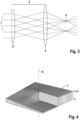
- a phase manipulation element in the form of a phase plate, through which a helical phase shift is imposed on the beam, is in Figure 4
- the phase plate 7, which is made of quartz glass, for example, has a varying thickness in the radial direction and/or in the circumferential direction with respect to the beam axis 6. To generate the helical phase term, the thickness increases in proportion to the angle in the circumferential direction.
- phase plate can be used which has several concentric "ramps", ie several concentric, ring-shaped sections with different proportional to the Angle of varying thickness in the circumferential direction.
- a spatial light modulator SLM that is suitably controlled is suitable as a phase manipulation element.
- the phase manipulation element can be arranged at any point in the beam path.
- the phase manipulation element is preferably arranged in the focal plane.
- Beam pre-forming can be carried out by means of a beam pre-forming element 8, as shown in the Figure 5 is shown.
- 0 denotes the beam coming in from the left with a Gaussian beam profile, for example. This passes through a concave axicon 9 and a convex axicon 10, which is positioned at a distance downstream of this in the beam path. The result is the ring-shaped light beam 1, which strikes the ring lens 3 of the beam-forming element 2.
- the diameter of the ring beam can be adjusted by the distance between the axicons 9, 10.
- the beam pre-forming element 8 can be used to increase the efficiency of generating the Bessel beam 5.
- the beam-forming element 2 comprises only a single monolithic element in which the concave ring lens 3 and the Fourier lens 4 are formed integrally with each other. Similar to the embodiment shown in the Figure 2 In the arrangement shown, the focal planes of the Fourier lens 4 and the ring lens 3 coincide on the side of the beam-forming element 2 facing the incident beam 1. This is a Galilean configuration. In a corresponding manner, a monolithic beam-forming element 2 can also be realized in a Keppler configuration, in which the focal plane is then located on the inside. Such a design would be correspondingly larger in volume.
- the lens surfaces of the ring lenses 3, 3' shown in the figures can be spherical or aspherical. In the simplest case, spherical surfaces are used.
- the inventive principle for generating a Bessel beam can be used in the optical spectral range, eg for laser systems. However, the principle can also be applied in other wavelength ranges, such as in the microwave or radio wave range.
- the advantages of the arrangement according to the invention are the following: Superpositions of Bessel beams can be generated simply and directly. They do not require complex and therefore lossy structures.
- the optical components used (ring lens, Fourier lens) do not have any protruding or sharp-edged structures and are therefore less susceptible to mechanical damage.
- the arrangement according to the invention has low losses and a high damage threshold, so that it is suitable for use in the high-performance range. In the arrangement according to the invention, it is not the ring lens but the Fourier optics that define the maximum aperture diameter. Therefore, the most complex component of the arrangement (the ring lens) is not necessarily the largest component at the same time.
- the arrangement according to the invention can be used, for example, in the field of material processing.
- Bessel beams have a more extensive focus than conventional beam shapes and show self-healing properties in the propagation direction. This makes Bessel beams interesting for various types of material processing such as cutting, drilling, welding, lithography and medical applications.
- the extended focus of Bessel beams can also be used in the field of microscopy to achieve a greater depth of field, to image deeper tissue layers in medical applications and to accelerate scanning processes.
- Bessel beams can be used advantageously for so-called optical tweezers.
- Bessel beams and their superpositions can be used to transport, align or rotate microscopic particles or individual biological cells. Bessel beams can also be used advantageously in the field of measurement technology. Optical remote measurement methods require good beam quality despite disruptive external influences.
- the self-healing properties of Bessel beams along the propagation direction are therefore advantageous for atmospheric applications, interferometry and depth spectroscopy.
Landscapes
- Physics & Mathematics (AREA)
- General Physics & Mathematics (AREA)
- Optics & Photonics (AREA)
- Optical Modulation, Optical Deflection, Nonlinear Optics, Optical Demodulation, Optical Logic Elements (AREA)
- Lasers (AREA)
Description
- Die Erfindung betrifft eine Anordnung zur Erzeugung eines Bessel-Strahls, mit einem Strahlformungselement, das einen als ebene elektromagnetische Welle einfallenden Strahl in einen Bessel-Strahl transformiert, wobei das Strahlformungselement wenigstens eine Ringlinse und eine Fourieroptik umfasst.
- Unter einem Bessel-Strahl versteht man eine spezielle Form von elektromagnetischen Wellen, insbesondere Lichtstrahlen, deren wesentliche Eigenschaft ist, dass sie nicht beugend sind, das Strahlprofil bleibt während der Ausbreitung erhalten.
- Häufig wird für einen real erzeugten Bessel-Strahl der Begriff "Bessel-Gauß-Strahl" verwendet, da ein idealer Bessel-Strahl aus physikalischen Gründen nicht erzeugt werden kann. Auf diese Unterscheidung wird im Folgenden verzichtet. Die Erfindung bezieht sich auf unter realen Bedingungen erzeugte, d.h. nichtideale Bessel-Strahlen.
- Es ist aus dem Stand der Technik bekannt, zur Erzeugung eines Bessel-Strahls ein Strahlformungselement zu verwenden, das einen als ebene elektromagnetische Welle einfallenden Strahl in einen Bessel-Strahl transformiert. Da es sich bei einem Bessel-Strahl um eine konische Superposition ebener Wellen handelt, werden im Stand der Technik als Strahlformungselemente hauptsächlich konische Linsen, so genannte Axicons verwendet (vgl. J. Arlt und K. Dholakia: "Generation of high-order Bessel beams by use of an axicon", Optics Communications 177.1-6, 2000, S. 297-301). Diese weisen eine hohe Effizienz auf, sind aber recht unflexibel, wenn es darum geht, mehrere Strahlen miteinander zu kombinieren. Darüber hinaus sind Axicons aufgrund der zentralen Spitze schwierig in guter Qualität herzustellen, entsprechend teuer und außerdem anfällig in Bezug auf Beschädigungen.
- Eine weitere Anordnung zur Erzeugung von Bessel-Strahlen in einer Kepler-Konfiguration ist aus der
GB 2 256 338 A - Sollen aufwändigere Varianten von Bessel-Strahlen erzeugt werden, wie z.B. Bessel-Strahlen höherer Ordnung, werden im Stand der Technik häufig räumliche Lichtmodulatoren (SLMs) verwendet. Diese sind nach Art von Flüssigkristall-Displays ausgestaltet, die eine räumlich variable Phasen- und/oder Amplitudenmodulation der einfallenden ebenen elektromagnetischen Wellen ermöglichen. SLMs werden mittels Computern angesteuert. Sie sind äußerst flexibel einsetzbar. Die Verwendung von SLMs ist allerdings aufwendig und teuer. Ein weiterer Nachteil ist, dass SLMs eine niedrige Zerstörschwelle und hohe Verluste bei der Strahlumformung aufweisen.
- Vor diesem Hintergrund ist es Aufgabe der Erfindung, eine gegenüber dem Stand der Technik verbesserte Anordnung zur Erzeugung eines Bessel-Strahls bereitzustellen. Die oben beschriebenen Nachteile der konventionellen Erzeugung von Bessel-Strahlen sollen vermieden werden.
- Diese Aufgabe löst die Erfindung ausgehend von einer Anordnung der eingangs angegebenen Art dadurch, dass die Fourieroptik eine Fourierlinse ist, wobei die Fokusebenen der Ringlinse und der Fourierlinse zusammenfallen, so dass die Ringlinse und die Fourierlinse eine Galilei-Konfiguration bilden, wobei die Ringlinse mit der Fourierlinse einstückig ausgebildet ist, wie im Anspruch 1 definiert.
- Die erfindungsgemäße Erzeugung des Bessel-Strahls basiert auf dem Fourier-Prinzip. Ein Bessel-Strahl ist, wie oben bereits erwähnt, eine konische Superposition ebener Wellen. Entsprechend ist das Raumwinkelspektrum des Bessel-Strahls durch einen scharfen, kreisförmigen Ring gegeben. Der Bessel-Strahl ergibt sich durch räumliche Fourier-Transformation eines solchen Rings. Gemäß der Erfindung wird zur Erzeugung ringförmiger Strahlung eine Ringlinse verwendet. Die Ringlinse weist eine ringförmige, gekrümmte Oberfläche auf, die, im Querschnitt gesehen, einer Zylinderlinse entspricht, die in sich, z.B. zu einem Kreis, geschlossen ist. Die Ringlinse erzeugt in ihrer Fokusebene ein scharfes ringförmiges Strahlprofil. Dieses wird mittels der im Strahlverlauf der Ringlinse nachgeordneten Fourieroptik räumlich Fourier-transformiert. Das Resultat ist der gewünschte Bessel-Strahl. Die erfindungsgemäße Ringlinse kann, muss aber nicht zwingend kreisringförmig sein. Abweichende Ringformen, beispielsweise elliptische Formen, sind ebenfalls denkbar, um entsprechende Varianten von Bessel-Strahlen zu erzeugen.
- Die Fourier-Transformation erfolgt erfindungsgemäß durch eine Fourierlinse, d.h. eine beliebige Sammellinse, die, der Ringlinse nachgeordnet, als Fourieroptik eingesetzt wird.
- Das Strahlformungselement der erfindungsgemäßen Anordnung ist besonders kompakt, indem die Ringlinse mit der Fourierlinse einstückig ausgebildet wird. Hierzu kann das Strahlformungselement auf der der einfallenden ebenen Welle zugewandten Oberfläche eine konkave Ringlinse aufweisen. Die gegenüberliegende Oberfläche ist gekrümmt ausgebildet und bildet so die Fourierlinse aus. Die zusammenfallenden Fokusebenen der Ringlinse und der Fourierlinse liegen z.B. auf der der einfallenden ebenen Welle zugewandten Seite des Strahlformungselementes in einer gemeinsamen Ebene (Galilei-Konfiguration). Allgemein können die Ringlinse und die Fourierlinse einer Kepler-Konfiguration oder eine Galilei-Konfiguration bilden. Der Bessel-Strahl kann entsprechend entweder mit oder ohne Zwischenfokus erzeugt werden.
- Zur Superposition mehrerer Bessel-Strahlen kann das Strahlformungselement der erfindungsgemäßen Anordnung zwei oder mehr konzentrische Ringlinsen aufweisen. Deren Fokusebenen sollten vorzugsweise zusammenfallen. Die konzentrischen Ringlinsen erzeugen in ihrer gemeinsamen Fokusebene ein Strahlprofil mit Ringen unterschiedlicher Durchmesser, die durch die Fourieroptik in entsprechend überlagerte Bessel-Strahlen transformiert werden.
- Bessel-Strahlen höherer Ordnung sind dadurch charakterisiert, dass sie zusätzlich zu ihrem ringförmigen Raumwinkelspektrum einen helikalen Phasenterm N-ter Ordnung aufweisen. N steht dabei für den Phasenhub nach einer vollen Umdrehung in Umfangsrichtung in Vielfachen von 2π. Zur Erzeugung eines Bessel-Strahls höherer Ordnung kann entsprechend im Strahlengang der erfindungsgemäßen Anordnung ein Phasenmanipulationselement angeordnet sein, das dem Strahl eine über den Strahlquerschnitt variierende Phasenverschiebung aufprägt, insbesondere eine helikale Phasenverschiebung. Praktisch realisiert werden kann dies z.B. durch eine Phasenplatte, die aus einem Material mit gegenüber der Umgebung abweichendem Brechungsindex besteht und bezüglich der Strahlachse in radialer Richtung und in Umfangsrichtung eine variierende Dicke aufweist, um so die gewünschte helikale Phasenverschiebung zu erhalten.
- Vorzugsweise weist das Strahlformungselement der erfindungsgemäßen Anordnung eine ringförmige Apertur auf, die mit der Ringlinse korrespondiert. Dadurch wird ausschließlich die ringförmige Strahlung im Fokus der Ringlinse durch die Fourieroptik transformiert. Störende Anteile der Strahlung werden ausgeblendet.
- Um die Effizienz bei der Transformation der ebenen Welle in den Bessel-Strahl zu optimieren, kann bei der erfindungsgemäßen Anordnung ein dem Strahlformungselement im Strahlverlauf vorgeschaltetes Strahlvorformungselement vorgesehen sein, das den als ebene Welle einfallenden Lichtstrahl in einen Strahl mit ringförmigem Querschnitt transformiert. Das Strahlvorformungselement bewirkt, dass der einfallende Strahl vollständig in den Bessel-Strahl transformiert wird. Die Strahlvorformung erfolgt korrespondierend zur Geometrie der Ringlinse. Beispielsweise kann das Strahlvorformungselement ein konkaves Axicon und ein diesem im Strahlverlauf nachgeschaltetes konvexes Axicon umfassen.
- Ausführungsbeispiele der Erfindung werden nachfolgend anhand der Zeichnungen näher erläutert. Es zeigen:
- Figur 1:
- Anordnung in einer ersten Ausgestaltung (kein Ausführungsbeispiel der Erfindung);
- Figur 2:
- Anordnung in einer zweiten Ausgestaltung (kein Ausführungsbeispiel der Erfindung);
- Figur 3:
- Strahlformungselement mit mehreren konzentrischen Ringlinsen (kein Ausführungsbeispiel der Erfindung);
- Figur 4:
- Phasenplatte zur Erzeugung eines Bessel-Strahls höherer Ordnung;
- Figur 5:
- Strahlvorformungselement der erfindungsgemäßen Anordnung;
- Figur 6:
- erfindungsgemäße Anordnung mit einstückigem Strahlformungselement.
- Bei der in der
Figur 1 gezeigten Anordnung fällt ein Lichtstrahl 1 von links her ein. Die elektromagnetische Strahlung durchläuft ein Strahlformungselement 2, das durch eine konvexe Ringlinse 3 und eine Fourierlinse 4 gebildet ist. Durch das Strahlformungselement 2 wird der einfallende Strahl 1 in einen Bessel-Strahl 5 transformiert, der die Anordnung in derFigur 1 nach rechts verlässt. Es handelt sich um einen Bessel-Strahl 0. Ordnung. Die Brennweiten f1 und f2 der Ringlinse 3 bzw. der Fourierlinse 4 sind in derFigur 1 verzeichnet. Es ist zu erkennen, dass die Fokusebenen der Ringlinse 3 und der Fourierlinse 4 zusammenfallen. Somit bilden die Ringlinse 3 und die Fourierlinse 4 eine Kepler-Konfiguration, ähnlich einem Kepler-Teleskop. Die Ringlinse 3 erzeugt in der Fokusebene zwischen Ringlinse 3 und Fourierlinse 4 einen scharfen ringförmigen Strahlquerschnitt. Die dargestellte Anordnung weist also einen Zwischenfokus auf. - In der Anordnung der
Figur 2 kommt eine konkave Ringlinse 3 zum Einsatz. Die Anordnung weist keinen Zwischenfokus auf. Die Fokusebenen fallen auf der dem einfallenden Strahl 1 zugewandten Seite der Ringlinse 3 zusammen. Die Ringlinse 3 und die Fourierlinse 4 bilden eine Galilei-Konfiguration, ähnlich einem Galiliei-Teleskop. Die Vermeidung des Zwischenfokus ist bei Hochleistungsanwendungen von Vorteil. Außerdem ergibt sich eine deutlich kompaktere Bauweise. Nachteilig ist, dass in die Fokusebene, d.h. in die Fourierebene der Anordnung, nicht (z.B. durch Blenden) eingegriffen werden kann. Auch mit der in derFigur 2 dargestellten Anordnung wird ein Bessel-Strahl 0. Ordnung erzeugt. - Ist es erforderlich, mehrere Bessel-Strahlen zu überlagern, kann, wie in
Figur 3 gezeigt, ein Strahlformungselement 2 zum Einsatz kommen, das zwei (oder mehr) konzentrische Ringlinsen aufweist, deren Fokusebenen zusammenfallen. - Bei dem Ausführungsbeispiel der
Figur 3 sind zwei Ringlinsen miteinander einstückig in einem Linsenelement 3' integriert. Das Strahlformungselement 2 erzeugt einen entsprechend überlagerten Strahl 5'. InFigur 3 bilden das Linsenelement 3' und die Fourierlinse 4 wiederum eine Kepler-Konfiguration. - Das Strahlformungselement 2 weist bei den dargestellten Ausführungsbeispielen eine ringförmige Apertur auf, um die für die Erzeugung des Bessel-Strahls unerwünschten Anteile des einfallenden Strahls 1 auszublenden. Beispielsweise können die Ringlinsen 3, 3' bei den Ausführungsbeispielen der
Figuren 1, 2 und3 in den planen Bereichen, d.h. außerhalb der konvex bzw. konkav geformten ringförmigen Bereiche, reflektierend oder absorbierend beschichtet sein. Ebenso können die unerwünschten Anteile der Strahlung in der jeweiligen Fokusebene, z.B. durch eine geeignete Blendenanordnung, entfernt werden. - Bessel-Strahlen höherer Ordnung sind dadurch charakterisiert, dass sie zusätzlich zu ihrem ringförmigen Raumwinkelspektrum einen helikalen Phasenterm N-ter Ordnung aufweisen. Dieser kann durch ein im Strahlengang angeordnetes Phasenmanipulationselement erzeugt werden, das dem Strahl eine entsprechend über den Strahlquerschnitt variierende Phasenverschiebung aufprägt. Ein Phasenmanipulationselement in Form einer Phasenplatte, durch die dem Strahl eine helikale Phasenverschiebung aufgeprägt wird, ist in
Figur 4 dargestellt. Die Phasenplatte 7, die z.B. aus Quarzglas besteht, weist bezüglich der Strahlachse 6 in radialer Richtung und/oder in Umfangsrichtung eine variierende Dicke auf. Zur Erzeugung des helikalen Phasenterms wächst z.B. die Dicke proportional zum Winkel in Umfangsrichtung an. Zur Überlagerung mehrerer Bessel-Strahlen unterschiedlicher Ordnungen kann eine Phasenplatte verwendet werden, die mehrere konzentrische "Rampen" aufweist, d.h. mehrere konzentrische, ringförmige Abschnitte mit unterschiedlich proportional zum Winkel in Umfangsrichtung variierender Dicke. Alternativ eignet sich als Phasenmanipulationselement ein räumlicher Lichtmodulator (SLM), der geeignet angesteuert wird. Das Phasenmanipulationselement kann an beliebiger Stelle im Strahlengang angeordnet sein. Vorzugsweise ist das Phasenmanipulationselement in der Fokusebene angeordnet. - Eine Strahlvorformung kann mittels eines Strahlvorformungselementes 8 erfolgen, wie es in der
Figur 5 dargestellt ist. Mit 0 ist der von links einfallende Strahl mit z.B. gaußförmigem Strahlprofil bezeichnet. Dieser durchläuft ein konkaves Axicon 9 und ein diesem im Strahlverlauf mit Abstand nachgeschaltetes, konvexes Axicon 10. Das Resultat ist der ringförmige Lichtstrahl 1, der auf die Ringlinse 3 des Strahlformungselementes 2 auftrifft. Der Durchmesser des Ringstrahls kann durch den Abstand der Axicons 9, 10 justiert werden. Durch das Strahlvorformungselement 8 lässt sich die Effizienz bei der Erzeugung des Bessel-Strahls 5 steigern. - Bei dem in der
Figur 6 gezeigten Ausführungsbeispiel umfasst das Strahlformungselement 2 nur ein einzelnes monolithisches Element, indem die konkave Ringlinse 3 und die Fourierlinse 4 einstückig miteinander ausgebildet sind. Ähnlich wie bei der in derFigur 2 dargestellten Anordnung fallen die Fokusebenen der Fourierlinse 4 und der Ringlinse 3 auf der dem einfallenden Strahl 1 zugewandten Seite des Strahlformungselementes 2 zusammen. Es handelt sich um eine Galilei-Konfiguration. In entsprechender Art und Weise lässt sich ein monolithisches Strahlformungselement 2 auch in Keppler-Konfiguration realisieren, bei dem dann die Fokusebene im Inneren liegt. Eine solche Ausgestaltung wäre entsprechend großvolumiger. - Die Linsenoberflächen der in den Figuren gezeigten Ringlinsen 3, 3' können sphärisch oder auch asphärisch sein. Im einfachsten Fall werden sphärische Oberflächen verwendet.
- Das erfindungsgemäße Prinzip zur Erzeugung eines Bessel-Strahls kann im optischen Spektralbereich, z.B. für Lasersysteme, verwendet werden. Das Prinzip lässt sich jedoch auch in anderen Wellenlängenbereichen, wie z.B. im Bereich der Mikrowellen oder der Radiowellen, anwenden.
- Vorteile der erfindungsgemäßen Anordnung sind die folgenden: Überlagerungen von Bessel-Strahlen sind einfach und direkt zu erzeugen. Sie erfordern keine komplexen und damit verlustbehafteten Aufbauten. Die verwendeten optischen Komponenten (Ringlinse, Fourierlinse) besitzen keine abstehenden oder scharfkantigen Strukturen und sind damit wenig anfällig in Bezug auf mechanische Beschädigungen. Die erfindungsgemäße Anordnung weist geringe Verluste und eine hohe Zerstörschwelle auf, so dass sie für die Anwendung im Hochleistungsbereich geeignet ist. Bei der erfindungsgemäßen Anordnung definiert nicht die Ringlinse, sondern die darauf folgende Fourieroptik den maximalen Aperturdurchmesser. Daher ist die komplexeste Komponente der Anordnung (die Ringlinse) nicht gleichzeitig auch die notwendigerweise größte Komponente.
- Die erfindungsgemäße Anordnung kann z.B. im Bereich der Materialbearbeitung eingesetzt werden. Bessel-Strahlen weisen einen ausgedehnteren Fokus auf als konventionelle Strahlformen und zeigen Selbstheilungseigenschaften in Propagationsrichtung. Das macht Bessel-Strahlen interessant für verschiedene Arten der Materialbearbeitung wie Schneiden, Bohren, Schweißen sowie Lithographie und medizinische Anwendungen. Ebenso lässt sich der ausgedehnte Fokus von Bessel-Strahlen im Bereich der Mikroskopie einsetzen, um eine größere Schärfentiefe zu realisieren, tiefere Gewebeschichten bei medizinischen Anwendungen abzubilden sowie Rasterverfahren zu beschleunigen. Bessel-Strahlen können mit Vorteil für so genannte optische Pinzetten verwendet werden. Mit Bessel-Strahlen und deren Superpositionen können mikroskopische Teilchen oder einzelne biologische Zellen transportiert, ausgerichtet oder rotiert werden. Weiterhin sind Bessel-Strahlen vorteilhaft einsetzbar im Bereich der Messtechnik. Optische Fernmessverfahren erfordern eine gute Strahlqualität trotz störender externer Einflüsse. Die selbstheilenden Eigenschaften von Bessel-Strahlen entlang der Propagationsrichtung sind daher vorteilhaft für atmosphärische Anwendungen, Interferometrie und Tiefenspektroskopie.
Claims (8)
- Anordnung zur Erzeugung eines Bessel-Strahls (5), mit einem Strahlformungselement (2), das einen als ebene elektromagnetische Welle einfallenden Strahl (1) in einen Bessel-Strahl (5) transformiert, wobei das Strahlformungselement (2) wenigstens eine Ringlinse (3, 3') und eine Fourieroptik umfasst, wobei die Fourieroptik eine Fourierlinse (4) ist,
dadurch gekennzeichnet, dass das Strahlformungselement (2) ein monolithisches Element ist, in dem die konkave Ringlinse (3, 3`) und die Fourierlinse (4) in einer Galilei-Konfiguration einstückig miteinander ausgebildet sind, wobei die Fokusebenen der Ringlinse (3) und der Fourierlinse (4) auf der dem einfallenden Strahl (1) zugewandten Seite des Strahlformungselementes (2) zusammenfallen. - Anordnung nach Anspruch 1, dadurch gekennzeichnet, dass das Strahlformungselement (2) zwei oder mehr konzentrische Ringlinsen aufweist.
- Anordnung nach Anspruch 1 oder 2, gekennzeichnet durch ein im Strahlengang angeordnetes Phasenmanipulationselement, das dem Strahl eine über den Strahlquerschnitt variierende Phasenverschiebung aufprägt.
- Anordnung nach Anspruch 3, dadurch gekennzeichnet, dass das Phasenmanipulationselement dem Strahl eine helikale Phasenverschiebung aufprägt.
- Anordnung nach Anspruch 3 oder 4, dadurch gekennzeichnet, dass das Phasenmanipulationselement eine Phasenplatte (7) mit bezüglich der Strahlachse (6) in radialer Richtung und/oder in Umfangsrichtung variierender Dicke ist.
- Anordnung nach einem der Ansprüche 1 bis 5, dadurch gekennzeichnet, dass das Strahlformungselement (2) eine ringförmige Apertur aufweist.
- Anordnung nach einem der Ansprüche 1 bis 6, gekennzeichnet durch ein dem Strahlformungselement (2) im Strahlverlauf vorgeschaltetes Strahlvorformungselement (8), das den einfallenden Strahl (0) in einen Strahl (1) mit ringförmigem Querschnitt transformiert.
- Anordnung nach Anspruch 7,
dadurch gekennzeichnet, dass das Strahlvorformungselement (8) ein konkaves Axicon (9) und ein diesem im Strahlverlauf nachgeschaltetes konvexes Axicon (10) umfasst.
Applications Claiming Priority (4)
| Application Number | Priority Date | Filing Date | Title |
|---|---|---|---|
| DE102016112137 | 2016-07-01 | ||
| DE102016115844.5A DE102016115844A1 (de) | 2016-07-01 | 2016-08-25 | Anordnung zur Erzeugung eines Bessel-Strahls |
| EP17739487.1A EP3479162B1 (de) | 2016-07-01 | 2017-06-22 | Anordnung zur erzeugung eines bessel-strahls |
| PCT/EP2017/065343 WO2018001846A1 (de) | 2016-07-01 | 2017-06-22 | Anordnung zur erzeugung eines bessel-strahls |
Related Parent Applications (2)
| Application Number | Title | Priority Date | Filing Date |
|---|---|---|---|
| EP17739487.1A Division-Into EP3479162B1 (de) | 2016-07-01 | 2017-06-22 | Anordnung zur erzeugung eines bessel-strahls |
| EP17739487.1A Division EP3479162B1 (de) | 2016-07-01 | 2017-06-22 | Anordnung zur erzeugung eines bessel-strahls |
Publications (2)
| Publication Number | Publication Date |
|---|---|
| EP3955048A1 EP3955048A1 (de) | 2022-02-16 |
| EP3955048B1 true EP3955048B1 (de) | 2024-08-21 |
Family
ID=60662473
Family Applications (3)
| Application Number | Title | Priority Date | Filing Date |
|---|---|---|---|
| EP21195211.4A Active EP3955049B1 (de) | 2016-07-01 | 2017-06-22 | Anordnung zur erzeugung eines bessel-strahls |
| EP17739487.1A Active EP3479162B1 (de) | 2016-07-01 | 2017-06-22 | Anordnung zur erzeugung eines bessel-strahls |
| EP21195202.3A Active EP3955048B1 (de) | 2016-07-01 | 2017-06-22 | Anordnung zur erzeugung eines bessel-strahls |
Family Applications Before (2)
| Application Number | Title | Priority Date | Filing Date |
|---|---|---|---|
| EP21195211.4A Active EP3955049B1 (de) | 2016-07-01 | 2017-06-22 | Anordnung zur erzeugung eines bessel-strahls |
| EP17739487.1A Active EP3479162B1 (de) | 2016-07-01 | 2017-06-22 | Anordnung zur erzeugung eines bessel-strahls |
Country Status (4)
| Country | Link |
|---|---|
| US (1) | US11372254B2 (de) |
| EP (3) | EP3955049B1 (de) |
| DE (1) | DE102016115844A1 (de) |
| WO (1) | WO2018001846A1 (de) |
Families Citing this family (6)
| Publication number | Priority date | Publication date | Assignee | Title |
|---|---|---|---|---|
| CN110058416B (zh) * | 2018-11-13 | 2023-05-26 | 首都师范大学 | 一种用于产生远距离稳定传输贝塞尔光束的装置及方法 |
| US11686889B2 (en) | 2019-02-28 | 2023-06-27 | General Electric Company | Systems and methods for direct laser melting of metals using non-diffracting laser beams |
| CN110361864B (zh) * | 2019-04-11 | 2020-07-07 | 北京理工大学 | 基于惠更斯超颖表面产生贝塞尔光束阵列的方法 |
| CN109946843A (zh) * | 2019-05-08 | 2019-06-28 | 长春理工大学 | 一种双v型结构多局域空心光阱转换光束系统 |
| CN111240029B (zh) * | 2020-03-18 | 2021-09-10 | 中国工程物理研究院激光聚变研究中心 | 一种贝塞尔光束产生装置及其产生方法 |
| CN112496528A (zh) * | 2020-11-03 | 2021-03-16 | 深圳市韵腾激光科技有限公司 | 光路组件、激光切割头及激光切割设备 |
Family Cites Families (14)
| Publication number | Priority date | Publication date | Assignee | Title |
|---|---|---|---|---|
| GB2256338A (en) * | 1991-05-31 | 1992-12-02 | Marconi Gec Ltd | Alignment means |
| JPH11242130A (ja) * | 1998-02-26 | 1999-09-07 | Nec Corp | 合波機能内蔵光源モジュールとこれを用いた光増幅器および双方向光伝送装置 |
| US6819435B2 (en) * | 2000-04-12 | 2004-11-16 | Nano Or Technologies Inc. | Spatial and spectral wavefront analysis and measurement |
| DE10044522C2 (de) * | 2000-09-04 | 2002-08-01 | Fraunhofer Ges Forschung | Optische Anordnung zur Strahlführung |
| DE102004011190B4 (de) * | 2004-03-04 | 2006-11-16 | Forschungsverbund Berlin E.V. | Optischer Strahlformer mit einem Laser mit ultrakurzer Pulsdauer |
| DE102007063274B8 (de) * | 2007-12-20 | 2022-12-15 | Albert-Ludwigs-Universität Freiburg | Mikroskop |
| CN102109680A (zh) * | 2011-01-07 | 2011-06-29 | 深圳大学 | 一种基于相全息图产生任意阶次无衍射贝塞尔光束阵列的方法和装置 |
| US9124066B2 (en) * | 2012-05-02 | 2015-09-01 | Lawrence Livermore National Security, Llc | Diffractive optical elements for transformation of modes in lasers |
| DE102012218125A1 (de) * | 2012-10-04 | 2013-11-07 | Carl Zeiss Smt Gmbh | Axikonsystem, insbesondere einer mikrolithographischen Projektionsbelichtungsanlage |
| DE102014116957A1 (de) * | 2014-11-19 | 2016-05-19 | Trumpf Laser- Und Systemtechnik Gmbh | Optisches System zur Strahlformung |
| CN104880828A (zh) * | 2015-06-16 | 2015-09-02 | 华侨大学 | 可产生尺寸可调的单个局域空心光束的光学元件 |
| JP6667555B2 (ja) * | 2015-06-23 | 2020-03-18 | テラダイオード, インコーポレーテッド | レーザ送達システムにおけるビームパラメータ積を変動させるための光学要素配置 |
| CN105182523B (zh) * | 2015-09-23 | 2017-11-07 | 北京大学 | 一种基于一阶贝塞尔光束的sted超分辨显微镜及调节方法 |
| CN105607162B (zh) * | 2016-02-26 | 2017-06-20 | 上海嘉强自动化技术有限公司 | 一种聚焦获得长焦深贝塞尔高斯光束新型光学透镜 |
-
2016
- 2016-08-25 DE DE102016115844.5A patent/DE102016115844A1/de not_active Ceased
-
2017
- 2017-06-22 EP EP21195211.4A patent/EP3955049B1/de active Active
- 2017-06-22 US US16/313,667 patent/US11372254B2/en active Active
- 2017-06-22 EP EP17739487.1A patent/EP3479162B1/de active Active
- 2017-06-22 WO PCT/EP2017/065343 patent/WO2018001846A1/de not_active Ceased
- 2017-06-22 EP EP21195202.3A patent/EP3955048B1/de active Active
Also Published As
| Publication number | Publication date |
|---|---|
| WO2018001846A1 (de) | 2018-01-04 |
| EP3479162B1 (de) | 2021-11-10 |
| EP3955049A1 (de) | 2022-02-16 |
| EP3955048A1 (de) | 2022-02-16 |
| EP3955049B1 (de) | 2024-09-04 |
| US11372254B2 (en) | 2022-06-28 |
| US20200333611A1 (en) | 2020-10-22 |
| EP3479162A1 (de) | 2019-05-08 |
| DE102016115844A1 (de) | 2018-01-04 |
Similar Documents
| Publication | Publication Date | Title |
|---|---|---|
| EP3955049B1 (de) | Anordnung zur erzeugung eines bessel-strahls | |
| DE102013102442B4 (de) | Optische Vorrichtung zur Strahlformung | |
| EP4049071B1 (de) | Segmentiertes strahlformungselement und laserbearbeitungsanlage | |
| EP2556397B1 (de) | Verfahren und anordnung zum erzeugen eines laserstrahls mit unterschiedlicher strahlprofilcharakteristik mittels einer mehrfachclad-faser | |
| EP1370896B1 (de) | Element zur kombinierten symmetrisierung und homogenisierung eines strahlenbündels | |
| DE112013002113B4 (de) | Strahlformer | |
| DE102007057868A1 (de) | Vorrichtung zur Strahlformung | |
| EP0873566B1 (de) | Röntgenmikroskop mit zonenplatten | |
| WO2012095422A2 (de) | Vorrichtung zur umwandlung des profils einer laserstrahlung in laserstrahlung mit einer rotationssymmetrischen intensitätsverteilung | |
| EP3450083B1 (de) | Vorrichtung und verfahren zur materialbearbeitung | |
| EP2689285A1 (de) | Vorrichtung und verfahren zur aufweitung eines laserstrahls | |
| EP1793269B1 (de) | Vorrichtung zur Beeinflussung von Licht | |
| WO2022135909A1 (de) | Vorrichtung zur strahlbeeinflussung eines laserstrahls | |
| DE102012109937A1 (de) | Vorrichtung zur Beaufschlagung einer Innenseite eines Zylinders mit Licht sowie Strahltransformationsvorrichtung für eine derartige Vorrichtung | |
| DE102017210241A1 (de) | Optische Anordnung zur Umformung des Intensitätsprofils eines optischen Strahls | |
| DE102004011190B4 (de) | Optischer Strahlformer mit einem Laser mit ultrakurzer Pulsdauer | |
| DE10121747B4 (de) | Element zur kombinierten Symmetrisierung und Homogenisierung eines Strahlenbündels | |
| DE102017113945B4 (de) | Modulares optisches Baukastensystem für fokusnahe Strahldichteverteilungen mit alternierendem Strahldichteprofil | |
| DE102011102588A1 (de) | Optische Anordnung zum Umformen eines einfallenden Lichtstrahlbündels, Verfahren zum Umformen eines Lichtstrahlbündels zu einem Linienfokus sowie optische Vorrichtung dafür | |
| DE10044522C2 (de) | Optische Anordnung zur Strahlführung | |
| DE102017113947A1 (de) | Modulares optisches Baukastensystem für kollimierte Top-Hat Verteilung | |
| DE102010018538A1 (de) | Verfahren zur Modenbeeinflussung von optischer Strahlung in einem Medium | |
| DE102017115805B4 (de) | Vorrichtung zur Strahlformung von Laserstrahlung | |
| EP4453639A1 (de) | Lasersystem zur erzeugung einer laserlinie | |
| DE102022118491A1 (de) | Optische Anordnung zur Umwandlung eines Eingangslaserstrahls in einen linienartigen Ausgangsstrahls |
Legal Events
| Date | Code | Title | Description |
|---|---|---|---|
| PUAI | Public reference made under article 153(3) epc to a published international application that has entered the european phase |
Free format text: ORIGINAL CODE: 0009012 |
|
| STAA | Information on the status of an ep patent application or granted ep patent |
Free format text: STATUS: THE APPLICATION HAS BEEN PUBLISHED |
|
| AC | Divisional application: reference to earlier application |
Ref document number: 3479162 Country of ref document: EP Kind code of ref document: P |
|
| AK | Designated contracting states |
Kind code of ref document: A1 Designated state(s): AL AT BE BG CH CY CZ DE DK EE ES FI FR GB GR HR HU IE IS IT LI LT LU LV MC MK MT NL NO PL PT RO RS SE SI SK SM TR |
|
| RAP3 | Party data changed (applicant data changed or rights of an application transferred) |
Owner name: FRIEDRICH-SCHILLER-UNIVERSITAET JENA Owner name: FRAUNHOFER-GESELLSCHAFT ZUR FOERDERUNG DER ANGEWANDTEN FORSCHUNG E.V. |
|
| STAA | Information on the status of an ep patent application or granted ep patent |
Free format text: STATUS: REQUEST FOR EXAMINATION WAS MADE |
|
| 17P | Request for examination filed |
Effective date: 20220815 |
|
| RBV | Designated contracting states (corrected) |
Designated state(s): AL AT BE BG CH CY CZ DE DK EE ES FI FR GB GR HR HU IE IS IT LI LT LU LV MC MK MT NL NO PL PT RO RS SE SI SK SM TR |
|
| GRAP | Despatch of communication of intention to grant a patent |
Free format text: ORIGINAL CODE: EPIDOSNIGR1 |
|
| STAA | Information on the status of an ep patent application or granted ep patent |
Free format text: STATUS: GRANT OF PATENT IS INTENDED |
|
| INTG | Intention to grant announced |
Effective date: 20240313 |
|
| GRAS | Grant fee paid |
Free format text: ORIGINAL CODE: EPIDOSNIGR3 |
|
| GRAA | (expected) grant |
Free format text: ORIGINAL CODE: 0009210 |
|
| STAA | Information on the status of an ep patent application or granted ep patent |
Free format text: STATUS: THE PATENT HAS BEEN GRANTED |
|
| AC | Divisional application: reference to earlier application |
Ref document number: 3479162 Country of ref document: EP Kind code of ref document: P |
|
| AK | Designated contracting states |
Kind code of ref document: B1 Designated state(s): AL AT BE BG CH CY CZ DE DK EE ES FI FR GB GR HR HU IE IS IT LI LT LU LV MC MK MT NL NO PL PT RO RS SE SI SK SM TR |
|
| REG | Reference to a national code |
Ref country code: GB Ref legal event code: FG4D Free format text: NOT ENGLISH |
|
| REG | Reference to a national code |
Ref country code: CH Ref legal event code: EP |
|
| REG | Reference to a national code |
Ref country code: IE Ref legal event code: FG4D Free format text: LANGUAGE OF EP DOCUMENT: GERMAN |
|
| REG | Reference to a national code |
Ref country code: DE Ref legal event code: R096 Ref document number: 502017016377 Country of ref document: DE |
|
| P01 | Opt-out of the competence of the unified patent court (upc) registered |
Free format text: CASE NUMBER: APP_50790/2024 Effective date: 20240907 |
|
| REG | Reference to a national code |
Ref country code: LT Ref legal event code: MG9D |
|
| REG | Reference to a national code |
Ref country code: NL Ref legal event code: MP Effective date: 20240821 |
|
| PG25 | Lapsed in a contracting state [announced via postgrant information from national office to epo] |
Ref country code: NO Free format text: LAPSE BECAUSE OF FAILURE TO SUBMIT A TRANSLATION OF THE DESCRIPTION OR TO PAY THE FEE WITHIN THE PRESCRIBED TIME-LIMIT Effective date: 20241121 |
|
| PG25 | Lapsed in a contracting state [announced via postgrant information from national office to epo] |
Ref country code: NL Free format text: LAPSE BECAUSE OF FAILURE TO SUBMIT A TRANSLATION OF THE DESCRIPTION OR TO PAY THE FEE WITHIN THE PRESCRIBED TIME-LIMIT Effective date: 20240821 Ref country code: FI Free format text: LAPSE BECAUSE OF FAILURE TO SUBMIT A TRANSLATION OF THE DESCRIPTION OR TO PAY THE FEE WITHIN THE PRESCRIBED TIME-LIMIT Effective date: 20240821 Ref country code: PL Free format text: LAPSE BECAUSE OF FAILURE TO SUBMIT A TRANSLATION OF THE DESCRIPTION OR TO PAY THE FEE WITHIN THE PRESCRIBED TIME-LIMIT Effective date: 20240821 Ref country code: GR Free format text: LAPSE BECAUSE OF FAILURE TO SUBMIT A TRANSLATION OF THE DESCRIPTION OR TO PAY THE FEE WITHIN THE PRESCRIBED TIME-LIMIT Effective date: 20241122 Ref country code: PT Free format text: LAPSE BECAUSE OF FAILURE TO SUBMIT A TRANSLATION OF THE DESCRIPTION OR TO PAY THE FEE WITHIN THE PRESCRIBED TIME-LIMIT Effective date: 20241223 |
|
| PG25 | Lapsed in a contracting state [announced via postgrant information from national office to epo] |
Ref country code: BG Free format text: LAPSE BECAUSE OF FAILURE TO SUBMIT A TRANSLATION OF THE DESCRIPTION OR TO PAY THE FEE WITHIN THE PRESCRIBED TIME-LIMIT Effective date: 20240821 |
|
| PG25 | Lapsed in a contracting state [announced via postgrant information from national office to epo] |
Ref country code: LV Free format text: LAPSE BECAUSE OF FAILURE TO SUBMIT A TRANSLATION OF THE DESCRIPTION OR TO PAY THE FEE WITHIN THE PRESCRIBED TIME-LIMIT Effective date: 20240821 |
|
| PG25 | Lapsed in a contracting state [announced via postgrant information from national office to epo] |
Ref country code: IS Free format text: LAPSE BECAUSE OF FAILURE TO SUBMIT A TRANSLATION OF THE DESCRIPTION OR TO PAY THE FEE WITHIN THE PRESCRIBED TIME-LIMIT Effective date: 20241221 |
|
| PG25 | Lapsed in a contracting state [announced via postgrant information from national office to epo] |
Ref country code: HR Free format text: LAPSE BECAUSE OF FAILURE TO SUBMIT A TRANSLATION OF THE DESCRIPTION OR TO PAY THE FEE WITHIN THE PRESCRIBED TIME-LIMIT Effective date: 20240821 |
|
| PG25 | Lapsed in a contracting state [announced via postgrant information from national office to epo] |
Ref country code: RS Free format text: LAPSE BECAUSE OF FAILURE TO SUBMIT A TRANSLATION OF THE DESCRIPTION OR TO PAY THE FEE WITHIN THE PRESCRIBED TIME-LIMIT Effective date: 20241121 Ref country code: ES Free format text: LAPSE BECAUSE OF FAILURE TO SUBMIT A TRANSLATION OF THE DESCRIPTION OR TO PAY THE FEE WITHIN THE PRESCRIBED TIME-LIMIT Effective date: 20240821 |
|
| PG25 | Lapsed in a contracting state [announced via postgrant information from national office to epo] |
Ref country code: RS Free format text: LAPSE BECAUSE OF FAILURE TO SUBMIT A TRANSLATION OF THE DESCRIPTION OR TO PAY THE FEE WITHIN THE PRESCRIBED TIME-LIMIT Effective date: 20241121 Ref country code: PT Free format text: LAPSE BECAUSE OF FAILURE TO SUBMIT A TRANSLATION OF THE DESCRIPTION OR TO PAY THE FEE WITHIN THE PRESCRIBED TIME-LIMIT Effective date: 20241223 Ref country code: PL Free format text: LAPSE BECAUSE OF FAILURE TO SUBMIT A TRANSLATION OF THE DESCRIPTION OR TO PAY THE FEE WITHIN THE PRESCRIBED TIME-LIMIT Effective date: 20240821 Ref country code: NO Free format text: LAPSE BECAUSE OF FAILURE TO SUBMIT A TRANSLATION OF THE DESCRIPTION OR TO PAY THE FEE WITHIN THE PRESCRIBED TIME-LIMIT Effective date: 20241121 Ref country code: NL Free format text: LAPSE BECAUSE OF FAILURE TO SUBMIT A TRANSLATION OF THE DESCRIPTION OR TO PAY THE FEE WITHIN THE PRESCRIBED TIME-LIMIT Effective date: 20240821 Ref country code: LV Free format text: LAPSE BECAUSE OF FAILURE TO SUBMIT A TRANSLATION OF THE DESCRIPTION OR TO PAY THE FEE WITHIN THE PRESCRIBED TIME-LIMIT Effective date: 20240821 Ref country code: IS Free format text: LAPSE BECAUSE OF FAILURE TO SUBMIT A TRANSLATION OF THE DESCRIPTION OR TO PAY THE FEE WITHIN THE PRESCRIBED TIME-LIMIT Effective date: 20241221 Ref country code: HR Free format text: LAPSE BECAUSE OF FAILURE TO SUBMIT A TRANSLATION OF THE DESCRIPTION OR TO PAY THE FEE WITHIN THE PRESCRIBED TIME-LIMIT Effective date: 20240821 Ref country code: GR Free format text: LAPSE BECAUSE OF FAILURE TO SUBMIT A TRANSLATION OF THE DESCRIPTION OR TO PAY THE FEE WITHIN THE PRESCRIBED TIME-LIMIT Effective date: 20241122 Ref country code: FI Free format text: LAPSE BECAUSE OF FAILURE TO SUBMIT A TRANSLATION OF THE DESCRIPTION OR TO PAY THE FEE WITHIN THE PRESCRIBED TIME-LIMIT Effective date: 20240821 Ref country code: ES Free format text: LAPSE BECAUSE OF FAILURE TO SUBMIT A TRANSLATION OF THE DESCRIPTION OR TO PAY THE FEE WITHIN THE PRESCRIBED TIME-LIMIT Effective date: 20240821 Ref country code: BG Free format text: LAPSE BECAUSE OF FAILURE TO SUBMIT A TRANSLATION OF THE DESCRIPTION OR TO PAY THE FEE WITHIN THE PRESCRIBED TIME-LIMIT Effective date: 20240821 |
|
| PG25 | Lapsed in a contracting state [announced via postgrant information from national office to epo] |
Ref country code: RO Free format text: LAPSE BECAUSE OF FAILURE TO SUBMIT A TRANSLATION OF THE DESCRIPTION OR TO PAY THE FEE WITHIN THE PRESCRIBED TIME-LIMIT Effective date: 20240821 Ref country code: DK Free format text: LAPSE BECAUSE OF FAILURE TO SUBMIT A TRANSLATION OF THE DESCRIPTION OR TO PAY THE FEE WITHIN THE PRESCRIBED TIME-LIMIT Effective date: 20240821 Ref country code: SM Free format text: LAPSE BECAUSE OF FAILURE TO SUBMIT A TRANSLATION OF THE DESCRIPTION OR TO PAY THE FEE WITHIN THE PRESCRIBED TIME-LIMIT Effective date: 20240821 |
|
| PG25 | Lapsed in a contracting state [announced via postgrant information from national office to epo] |
Ref country code: EE Free format text: LAPSE BECAUSE OF FAILURE TO SUBMIT A TRANSLATION OF THE DESCRIPTION OR TO PAY THE FEE WITHIN THE PRESCRIBED TIME-LIMIT Effective date: 20240821 |
|
| PG25 | Lapsed in a contracting state [announced via postgrant information from national office to epo] |
Ref country code: CZ Free format text: LAPSE BECAUSE OF FAILURE TO SUBMIT A TRANSLATION OF THE DESCRIPTION OR TO PAY THE FEE WITHIN THE PRESCRIBED TIME-LIMIT Effective date: 20240821 |
|
| PG25 | Lapsed in a contracting state [announced via postgrant information from national office to epo] |
Ref country code: IT Free format text: LAPSE BECAUSE OF FAILURE TO SUBMIT A TRANSLATION OF THE DESCRIPTION OR TO PAY THE FEE WITHIN THE PRESCRIBED TIME-LIMIT Effective date: 20240821 Ref country code: SK Free format text: LAPSE BECAUSE OF FAILURE TO SUBMIT A TRANSLATION OF THE DESCRIPTION OR TO PAY THE FEE WITHIN THE PRESCRIBED TIME-LIMIT Effective date: 20240821 |
|
| REG | Reference to a national code |
Ref country code: DE Ref legal event code: R097 Ref document number: 502017016377 Country of ref document: DE |
|
| PLBE | No opposition filed within time limit |
Free format text: ORIGINAL CODE: 0009261 |
|
| STAA | Information on the status of an ep patent application or granted ep patent |
Free format text: STATUS: NO OPPOSITION FILED WITHIN TIME LIMIT |
|
| 26N | No opposition filed |
Effective date: 20250522 |
|
| PG25 | Lapsed in a contracting state [announced via postgrant information from national office to epo] |
Ref country code: SE Free format text: LAPSE BECAUSE OF FAILURE TO SUBMIT A TRANSLATION OF THE DESCRIPTION OR TO PAY THE FEE WITHIN THE PRESCRIBED TIME-LIMIT Effective date: 20240821 |
|
| PGFP | Annual fee paid to national office [announced via postgrant information from national office to epo] |
Ref country code: GB Payment date: 20251211 Year of fee payment: 9 |
|
| PGFP | Annual fee paid to national office [announced via postgrant information from national office to epo] |
Ref country code: FR Payment date: 20251212 Year of fee payment: 9 |
|
| REG | Reference to a national code |
Ref country code: CH Ref legal event code: H13 Free format text: ST27 STATUS EVENT CODE: U-0-0-H10-H13 (AS PROVIDED BY THE NATIONAL OFFICE) Effective date: 20260127 |
|
| PG25 | Lapsed in a contracting state [announced via postgrant information from national office to epo] |
Ref country code: MC Free format text: LAPSE BECAUSE OF FAILURE TO SUBMIT A TRANSLATION OF THE DESCRIPTION OR TO PAY THE FEE WITHIN THE PRESCRIBED TIME-LIMIT Effective date: 20240821 |
|
| PG25 | Lapsed in a contracting state [announced via postgrant information from national office to epo] |
Ref country code: LU Free format text: LAPSE BECAUSE OF NON-PAYMENT OF DUE FEES Effective date: 20250622 |
|
| REG | Reference to a national code |
Ref country code: BE Ref legal event code: MM Effective date: 20250630 |
|
| PG25 | Lapsed in a contracting state [announced via postgrant information from national office to epo] |
Ref country code: IE Free format text: LAPSE BECAUSE OF NON-PAYMENT OF DUE FEES Effective date: 20250622 |
|
| PGFP | Annual fee paid to national office [announced via postgrant information from national office to epo] |
Ref country code: DE Payment date: 20251222 Year of fee payment: 9 |
|
| PG25 | Lapsed in a contracting state [announced via postgrant information from national office to epo] |
Ref country code: BE Free format text: LAPSE BECAUSE OF NON-PAYMENT OF DUE FEES Effective date: 20250630 |
|
| PG25 | Lapsed in a contracting state [announced via postgrant information from national office to epo] |
Ref country code: CH Free format text: LAPSE BECAUSE OF NON-PAYMENT OF DUE FEES Effective date: 20250630 |