EP3955037B1 - Vorrichtung für optische kommunikation - Google Patents
Vorrichtung für optische kommunikation Download PDFInfo
- Publication number
- EP3955037B1 EP3955037B1 EP19927484.6A EP19927484A EP3955037B1 EP 3955037 B1 EP3955037 B1 EP 3955037B1 EP 19927484 A EP19927484 A EP 19927484A EP 3955037 B1 EP3955037 B1 EP 3955037B1
- Authority
- EP
- European Patent Office
- Prior art keywords
- sub
- wavelength
- light beams
- component
- lens
- Prior art date
- Legal status (The legal status is an assumption and is not a legal conclusion. Google has not performed a legal analysis and makes no representation as to the accuracy of the status listed.)
- Active
Links
Images






Classifications
-
- G—PHYSICS
- G02—OPTICS
- G02B—OPTICAL ELEMENTS, SYSTEMS OR APPARATUS
- G02B6/00—Light guides; Structural details of arrangements comprising light guides and other optical elements, e.g. couplings
- G02B6/24—Coupling light guides
- G02B6/26—Optical coupling means
- G02B6/35—Optical coupling means having switching means
- G02B6/354—Switching arrangements, i.e. number of input/output ports and interconnection types
-
- G—PHYSICS
- G02—OPTICS
- G02B—OPTICAL ELEMENTS, SYSTEMS OR APPARATUS
- G02B6/00—Light guides; Structural details of arrangements comprising light guides and other optical elements, e.g. couplings
- G02B6/24—Coupling light guides
- G02B6/26—Optical coupling means
- G02B6/35—Optical coupling means having switching means
- G02B6/354—Switching arrangements, i.e. number of input/output ports and interconnection types
- G02B6/356—Switching arrangements, i.e. number of input/output ports and interconnection types in an optical cross-connect device, e.g. routing and switching aspects of interconnecting different paths propagating different wavelengths to (re)configure the various input and output links
-
- G—PHYSICS
- G02—OPTICS
- G02B—OPTICAL ELEMENTS, SYSTEMS OR APPARATUS
- G02B6/00—Light guides; Structural details of arrangements comprising light guides and other optical elements, e.g. couplings
- G02B6/24—Coupling light guides
- G02B6/26—Optical coupling means
- G02B6/27—Optical coupling means with polarisation selective and adjusting means
- G02B6/2753—Optical coupling means with polarisation selective and adjusting means characterised by their function or use, i.e. of the complete device
- G02B6/278—Controlling polarisation mode dispersion [PMD], e.g. PMD compensation or emulation
-
- G—PHYSICS
- G02—OPTICS
- G02B—OPTICAL ELEMENTS, SYSTEMS OR APPARATUS
- G02B6/00—Light guides; Structural details of arrangements comprising light guides and other optical elements, e.g. couplings
- G02B6/24—Coupling light guides
- G02B6/26—Optical coupling means
- G02B6/28—Optical coupling means having data bus means, i.e. plural waveguides interconnected and providing an inherently bidirectional system by mixing and splitting signals
- G02B6/293—Optical coupling means having data bus means, i.e. plural waveguides interconnected and providing an inherently bidirectional system by mixing and splitting signals with wavelength selective means
- G02B6/29379—Optical coupling means having data bus means, i.e. plural waveguides interconnected and providing an inherently bidirectional system by mixing and splitting signals with wavelength selective means characterised by the function or use of the complete device
- G02B6/29395—Optical coupling means having data bus means, i.e. plural waveguides interconnected and providing an inherently bidirectional system by mixing and splitting signals with wavelength selective means characterised by the function or use of the complete device configurable, e.g. tunable or reconfigurable
-
- H—ELECTRICITY
- H04—ELECTRIC COMMUNICATION TECHNIQUE
- H04J—MULTIPLEX COMMUNICATION
- H04J14/00—Optical multiplex systems
- H04J14/02—Wavelength-division multiplex systems
- H04J14/0201—Add-and-drop multiplexing
- H04J14/0202—Arrangements therefor
- H04J14/0204—Broadcast and select arrangements, e.g. with an optical splitter at the input before adding or dropping
-
- H—ELECTRICITY
- H04—ELECTRIC COMMUNICATION TECHNIQUE
- H04J—MULTIPLEX COMMUNICATION
- H04J14/00—Optical multiplex systems
- H04J14/02—Wavelength-division multiplex systems
- H04J14/0201—Add-and-drop multiplexing
- H04J14/0202—Arrangements therefor
- H04J14/021—Reconfigurable arrangements, e.g. reconfigurable optical add/drop multiplexers [ROADM] or tunable optical add/drop multiplexers [TOADM]
- H04J14/0212—Reconfigurable arrangements, e.g. reconfigurable optical add/drop multiplexers [ROADM] or tunable optical add/drop multiplexers [TOADM] using optical switches or wavelength selective switches [WSS]
-
- H—ELECTRICITY
- H04—ELECTRIC COMMUNICATION TECHNIQUE
- H04J—MULTIPLEX COMMUNICATION
- H04J14/00—Optical multiplex systems
- H04J14/02—Wavelength-division multiplex systems
- H04J14/0201—Add-and-drop multiplexing
- H04J14/0215—Architecture aspects
- H04J14/0217—Multi-degree architectures, e.g. having a connection degree greater than two
-
- G—PHYSICS
- G02—OPTICS
- G02B—OPTICAL ELEMENTS, SYSTEMS OR APPARATUS
- G02B6/00—Light guides; Structural details of arrangements comprising light guides and other optical elements, e.g. couplings
- G02B6/24—Coupling light guides
- G02B6/26—Optical coupling means
- G02B6/27—Optical coupling means with polarisation selective and adjusting means
- G02B6/2706—Optical coupling means with polarisation selective and adjusting means as bulk elements, i.e. free space arrangements external to a light guide, e.g. polarising beam splitters
-
- G—PHYSICS
- G02—OPTICS
- G02B—OPTICAL ELEMENTS, SYSTEMS OR APPARATUS
- G02B6/00—Light guides; Structural details of arrangements comprising light guides and other optical elements, e.g. couplings
- G02B6/24—Coupling light guides
- G02B6/26—Optical coupling means
- G02B6/28—Optical coupling means having data bus means, i.e. plural waveguides interconnected and providing an inherently bidirectional system by mixing and splitting signals
- G02B6/293—Optical coupling means having data bus means, i.e. plural waveguides interconnected and providing an inherently bidirectional system by mixing and splitting signals with wavelength selective means
- G02B6/29304—Optical coupling means having data bus means, i.e. plural waveguides interconnected and providing an inherently bidirectional system by mixing and splitting signals with wavelength selective means operating by diffraction, e.g. grating
- G02B6/29305—Optical coupling means having data bus means, i.e. plural waveguides interconnected and providing an inherently bidirectional system by mixing and splitting signals with wavelength selective means operating by diffraction, e.g. grating as bulk element, i.e. free space arrangement external to a light guide
- G02B6/29311—Diffractive element operating in transmission
Definitions
- This application relates to the communications field, and in particular, to an optical communications apparatus.
- a network node requires more dimensions (or transmission paths) of a cross-connection.
- the operator may use a reconfigurable optical add/drop multiplexer (reconfigurable optical add/drop multiplexer, ROADM) to remotely and automatically switch the dimensions to replace an original manual site visit manner to change an optical fiber connection, so as to meet a requirement for a dynamic network connection.
- ROADM reconfigurable optical add/drop multiplexer
- ROADM CDC ROADM for short
- colorless wavelength-independent
- directionless directionless
- contentionless no wavelength conflict
- an ROADM may include a line-side 1 x K WSS and a client-side N x M add/drop wavelength selective switch (add/drop wavelength selective switch, ADWSS).
- the line-side 1 x K wavelength selective switch (wavelength selective switch, WSS) is used to introduce input signals from N dimensions over a transmission link to an input port of the N x M ADWSS by using an optical switch array, so that signal light beams from various dimensions are incident onto a first optical switch array of the N x M ADWSS.
- two optical switch arrays of the N x M ADWSS complete signal switching, and propagate a switched signal to an output port.
- the 1 x K WSS includes one optical switch array
- the N x M ADWSS includes two optical switch arrays.
- a to-be-dropped signal passes through three optical switch arrays in total.
- a to-be-added signal also needs to pass through three optical switch arrays to switch a locally added service to each dimension. Because the to-be-dropped signal and the to-be-added signal each need to pass through the three optical switch arrays, relatively large insertion losses and relatively large filtering are caused for the signals.
- CN 107003480 A1 discloses a wavelength selection switch device, communication equipment and wavelength switching method.
- the wavelength selection switch device includes incident outgoing unit (10), wavelength dispersion synthesis unit (20), light beam focusing unit (30), the first beam deflecting element (40), light chopper unit (50) and the second beam deflecting element (60).
- the incident outgoing unit (10) includes M entry port and N number of exit ports.
- First beam deflecting element (40) includes and one-to-one M incident sub-block of M entry port
- second beam deflecting element (60) includes including multiple deflection areas corresponding with multiple wavelength difference respectively with the one-to-one N number of outgoing sub-block of N number of exit ports, each incidence sub-block and each outgoing sub-block.
- US20130216183 A1 discloses a wavelength-selective cross-connect (WSXC) device having N input ports and M output ports and configured to route any set of one or more carrier wavelengths from a corresponding input port to any selected output port.
- the WSXC device includes a diffraction grating and a beam-steering device optically coupled to each other and to the input/output ports so that each of the carrier wavelengths traverses the diffraction grating and the beam-steering device two or more times en route from the respective input port to a designated output port.
- This application provides an optical communications apparatus.
- An optical path from an input port from a dimension to output from a dimension needs to pass through only two optical switch arrays, and an optical path from the input port from a dimension to output to drop a signal also needs to pass through only two optical switch arrays. In this way, insertion losses caused by one optical switch array are reduced for a to-be-dropped signal.
- the invention provides an optical communications apparatus in accordance with claim 1.
- Optional features of the optical communications apparatus are defined in dependent claims 2-15.
- the light beam output from a dimension can bypass the optical path for output to drop a signal, and be output from the output port from a dimension.
- the optical path of the first light beam from the input port from a dimension to the output from a dimension needs to pass through only the two optical switch arrays (the optical switch array and the second optical switch array that are included in the optical deflection component), and the optical path of the first light beam from the input port from a dimension to the output to drop a signal also needs to pass through only the two optical switch arrays (the optical switch array and the third optical switch array that are included in the optical deflection component). In this way, insertion losses caused by the one optical switch array are reduced for the to-be-dropped signal, and filtering of the optical switch array is reduced for the to-be-dropped signal. This reduces the signal filtering penalty.
- the technical solutions of the present invention may be applied to various communications systems that can use signal light to transmit data, for example, a global system for mobile communications (global system of mobile communications, GSM), a code division multiple access (code division multiple access, CDMA) system, a wideband code division multiple access (wideband code division multiple access, WCDMA) system, and a general packet radio service (general packet radio service, GPRS) system, a long term evolution (long term evolution, LTE) system, and a fifth generation (5th Generation, 5G) communications system.
- GSM global system of mobile communications
- CDMA code division multiple access
- WCDMA wideband code division multiple access
- GPRS general packet radio service
- LTE long term evolution
- 5G fifth generation
- the communications system may be further applicable to a future-oriented communications technology, and is applicable to the technical solutions provided in the embodiments of the present invention.
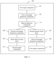
- FIG. 2 is a schematic architectural diagram of an optical communications apparatus according to an embodiment of the present invention.
- the optical communications apparatus in this embodiment may be a reconfigurable optical add/drop multiplexer ROADM.
- an ROADM architecture provided in this embodiment of the present invention includes a first input component 201, a first wavelength dispersion component 202, an optical deflection component 211, a second wavelength dispersion component 208, a third optical switch array 209, a second output component 210, a second optical switch array 205, a third wavelength dispersion component 206, and a first output component 207.
- the first input component 201 is configured to input a first light beam and propagate the first light beam to the first wavelength dispersion component 202.
- the first input component 201 may include N input ports.
- the N input ports are configured for input from a dimension, and the first input component 201 is configured to output input light beams received by the N input ports to the first wavelength dispersion component 202.
- the first input component 201 may make the first light beam input from a dimension incident to the first wavelength dispersion component 202.
- a value of N in this embodiment is a positive integer.
- the first wavelength dispersion component 202 is configured to decompose the first light beam incident from the first input component 201 into a plurality of first sub-wavelength light beams, and propagate the plurality of first sub-wavelength light beams to the optical deflection component 211.
- the first wavelength dispersion component 202 may decompose the first light beam incident from the first input component 201 into the plurality of first sub-wavelength light beams, so that the plurality of first sub-wavelength light beams are dispersed on a wavelength plane, and the plurality of dispersed first sub-wavelength light beams are propagated to the optical deflection component 211 through a redirection component 203. Wavelengths of the first sub-wavelength light beams are different from each other.
- the optical deflection component 211 is configured to perform angle deflection on the plurality of first sub-wavelength light beams to obtain a plurality of second sub-wavelength light beams, and propagate the plurality of second sub-wavelength light beams to the second optical switch array 205.
- the optical deflection component 211 is further configured to perform angle deflection on the plurality of first sub-wavelength light beams to obtain a plurality of third sub-wavelength light beams, and propagate the plurality of third sub-wavelength light beams to the second wavelength dispersion component 208.
- a light beam propagation direction of the second sub-wavelength light beam is different from that of the third sub-wavelength light beam.
- the second optical switch array 205 is configured to propagate the plurality of second sub-wavelength light beams to the third wavelength dispersion component 206.
- the third wavelength dispersion component 206 is configured to combine the plurality of second sub-wavelength light beams into a second light beam, and propagate the second light beam to the first output component 207.
- the first output component 207 is configured to output the second light beam from a dimension.
- the first output component 207 is configured to output the second light beam to different directions.
- the second wavelength dispersion component 208 is configured to combine the plurality of third sub-wavelength light beams into a third light beam, and propagate the third light beam to the third optical switch array 209.
- the third optical switch array 209 is configured to propagate the third light beam to a corresponding output port in the second output component 210.
- the second output component 210 is configured to output the third light beam to drop a signal.
- the optical deflection component 211 deflects the plurality of first sub-wavelength light beams in different light beam propagation directions for different output port types, so that the light beam output to drop a signal can bypass an optical path for output from a dimension, and be output from an output port to drop a signal.
- the light beam output from a dimension can bypass an optical path for output to drop a signal, and be output from an output port from a dimension.
- An optical path of the first light beam from an input port from a dimension to the output from a dimension needs to pass through only two optical switch arrays (the optical switch array and the second optical switch array 205 that are included in the optical deflection component 211), and an optical path of the first light beam from the input port from a dimension to the output to drop a signal also needs to pass through only two optical switch arrays (the optical switch array and the third optical switch array 209 that are included in the optical deflection component 211).
- insertion losses caused by one optical switch array are reduced for a to-be-dropped signal, and filtering of the optical switch array is reduced for the to-be-dropped signal. This reduces signal filtering penalty.
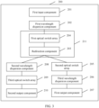
- FIG. 3 is a schematic architectural diagram of another optical communications apparatus according to an embodiment of this application.
- the optical deflection component 211 includes a first optical switch array 204 and the redirection component 203.
- the first optical switch array 204 is configured to perform angle deflection on the plurality of first sub-wavelength light beams to obtain the plurality of second sub-wavelength light beams, and propagate the plurality of second sub-wavelength light beams to the second optical switch array 205 through the redirection component 203.
- the first optical switch array 204 is further configured to perform angle deflection on the plurality of first sub-wavelength light beams to obtain the plurality of third sub-wavelength light beams, and propagate the plurality of third sub-wavelength light beams to the second wavelength dispersion component 208 through the redirection component 203.
- optical deflection component 211 includes the first optical switch array 204 and the redirection component 203.
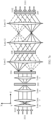
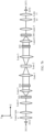
- FIG. 4 is a schematic structural diagram of an optical path of an optical communications apparatus on a wavelength plane according to an embodiment of the present invention.
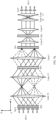
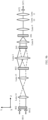
- FIG. 5a is a schematic structural diagram of an optical path of an optical communications apparatus on a port switching plane according to an embodiment of the present invention.
- FIG. 5b is a schematic structural diagram of an optical path of an optical communications apparatus on a port switching plane according to an embodiment of the present invention.
- the wavelength plane is a YOZ plane
- the port switching plane is an XOZ plane.
- FIG. 5a is a schematic structural diagram of an optical path from input from a dimension to output from a dimension
- FIG. 5b is a schematic structural diagram of an optical path from input from a dimension to output to drop a signal.
- the optical communications apparatus may include a first input component 201, a first wavelength dispersion component 202, a first optical switch array 204, a second wavelength dispersion component 208, a third optical switch array 209, a second output component 210, a second optical switch array 205, a third wavelength dispersion component 206, a first output component 207, and a lens 1 to a lens 15.
- the first input component 201 may include N input ports.
- the N input ports are configured for input from a dimension, and a value of N is a positive integer.
- the N input ports included in the first input component 201 may be arranged in a one-dimensional manner, and are configured to obtain light beams from N dimensions.
- the light beams from the N dimensions may be wavelength division multiplex (wavelength division multiplex, WDM) light beams.
- WDM wavelength division multiplex
- a first light beam in this embodiment may be a WDM light beam, and one WDM light beam may include a plurality of (at least two) sub-beams. Center wavelengths of the sub-beams (or center frequencies of the sub-beams) are different from each other, and the light beams from the N dimensions may come from different directions.
- the first light beam may be incident to one of the N input ports in the first input component 201.
- the first input component 201 may include an input optical fiber array 3011 and an input collimator array 3012.
- the input optical fiber array 3011 may include N input optical fibers arranged in a one-dimensional manner, and the N input optical fibers are configured to obtain light beams from various dimensions. Specifically, the input optical fiber array 3011 may include the N input optical fibers arranged in the one-dimensional manner on a port switching plane.
- the input collimator array 3012 may include N collimators arranged in a one-dimensional manner.
- the N collimators respectively correspond to the N input optical fibers, and the input collimator array 3012 is configured to convert light beams input by the N input optical fibers into collimated light beams.
- the input collimator array 3012 may include the N collimators arranged in the one-dimensional manner on the port switching plane.
- the N collimators one-to-one correspond to the N input optical fibers.
- One collimator is configured to collimate a light beam output from a corresponding input optical fiber. It may also be understood as converting the light beam input from the input optical fiber into a parallel light beam, and extending a waist value of the light beam to facilitate subsequent optical path processing.
- one of the N input optical fibers may obtain a first light beam from a dimension, and convert the first light beam into the collimated light beam by using a corresponding input collimator.
- the ROADM in this embodiment of this application may further include a spot beam expansion component including a plurality of lenses, and the spot beam expansion component is configured to change a spot size of the first light beam output by the first input component 201.
- the spot beam expansion component is configured to receive the first light beam output by the first input component 201, change a light beam characteristic of the first light beam, and then output the first light beam to the first wavelength dispersion component 202.
- the spot beam expansion component may include at least one lens.
- the lens 6 and the lens 7 constitute the spot beam expansion component configured to expand, on a wavelength plane, the collimated light beam generated by the first input component 201, and change a spot size on the first wavelength dispersion component 202.
- Focal lengths of the lens 6 and the lens 7 may be different, and are respectively f1 and f2.
- a spacing between the lens 6 and the lens 7 is a sum of f1 and f2.
- the spot beam expansion component is disposed, so that spot switching can be performed on the light beam output by the first input component 201, and the input light beam can better meet a processing characteristic of a subsequent optical element.
- the first wavelength dispersion component 202 is configured to decompose, on the wavelength plane, the first light beam incident from the first input component 201 into a plurality of first sub-wavelength light beams, so that the plurality of first sub-wavelength light beams are propagated to the first optical switch array 204.
- the first wavelength dispersion component 202 may decompose, in a diffraction manner, a light beam into sub-beams with different wavelengths (or center frequencies) on the wavelength plane, so that the first sub-wavelength light beams output from the first wavelength dispersion component 202 are radiatively dispersed in a wavelength plane direction. It should be noted that, on the port switching plane, the first wavelength dispersion component does not have a function of decomposing a light beam. In an incident direction of the light beam (namely, a direction from the first input component to the first optical switch array 204), the first wavelength dispersion component 202 is configured to receive the first light beam output by the first output component 201, and transmit the first light beam to the first optical switch array 204.
- the first wavelength dispersion component 202 may decompose a first light beam input from one input port into first sub-wavelength light beams with different wavelengths.
- the first wavelength dispersion component 202 may decompose the first light beam into the K first sub-wavelength light beams.
- the wavelengths of the K first sub-wavelength light beams are different from each other.
- the first wavelength dispersion component 202 may include at least one dispersion unit, for example, a grating.
- the first wavelength dispersion component 202 may be an arrayed waveguide grating, a reflection grating, a transmittance grating, a dispersion prism, or a planar waveguide grating.
- a combination of a plurality of gratings may be used, or an optical path may be adjusted to enable a light beam to pass through a same grating for a plurality of times.
- a redirection component 203 may be further included. Specifically, the redirection component 203 is configured to receive the plurality of first sub-wavelength light beams output by the first wavelength dispersion component 202, and redirect the plurality of first sub-wavelength light beams to one row of switch units in N rows of switch units in the first optical switch array 204.
- the redirection component 203 may be a lens group including a plurality of lenses.
- the lens group may include a convex lens and/or a concave lens.
- the redirection component 203 includes the lens 4 and the lens 5.
- the first wavelength dispersion component 202 is located on a back focal plane of the lens 4, and the first wavelength dispersion component 202 is located on a front focal plane of the lens 5.
- the lens 5 is configured to propagate the plurality of first sub-wavelength light beams incident from the first wavelength dispersion component 202 to the first optical switch array 204.
- focal lengths of the lens 4 and the lens 5 may be the same, to constitute a 4f (f is a focal length of the lens) system.
- the redirection component 203 may propagate each first sub-wavelength light beam to a corresponding location in the first optical switch array 204 by changing a light beam propagation route of each first sub-wavelength light beam.
- the plurality of first sub-wavelength light beams may be received from the first wavelength dispersion component 202, and light beam propagation characteristics of the plurality of first sub-wavelength light beams in the wavelength plane direction may be changed, so that sub-beams with different wavelengths are propagated to different positions of the first optical switch array 204 in the wavelength plane direction.
- the lens 4 may refract the first light beam on the port switching plane
- the first wavelength dispersion component 202 may demultiplex the first light beam on the back focal plane of the lens 4
- the lens 5 may refract the plurality of first sub-wavelength light beams on the wavelength plane and the port switching plane, so that a light beam propagation direction of the plurality of first sub-wavelength light beams output from the lens 5 is the same as a light beam propagation direction of the first light beam input to the lens 4.
- FIG. 4 is merely a schematic diagram, and the lens 4 and the lens 5 may alternatively be replaced with other components. This is not limited herein.
- the first optical switch array 204 is configured to perform angle deflection on the plurality of first sub-wavelength light beams to obtain a plurality of second sub-wavelength light beams, and propagate the plurality of second sub-wavelength light beams to the second optical switch array 205 through the redirection component 203.
- the first optical switch array 204 is further configured to perform angle deflection on the plurality of first sub-wavelength light beams to obtain a plurality of third sub-wavelength light beams, and propagate the plurality of third sub-wavelength light beams to the second wavelength dispersion component 208 through the redirection component 203.
- a light beam propagation direction of the second sub-wavelength light beam is different from that of the third sub-wavelength light beam.
- the first optical switch array 204 may deflect the plurality of first sub-wavelength light beams in different light beam propagation directions for different output port types, so that a light beam output to drop a signal can bypass an optical path for output from a dimension, and be output from an output port to drop a signal.
- a light beam output from a dimension can bypass an optical path for output to drop a signal, and be output from an output port from a dimension.
- the first optical switch array 204 may receive a deflection instruction from an optical switch controller. If the deflection instruction indicates that the plurality of first sub-wavelength light beams need to be output from a dimension, the first optical switch array 204 performs angle deflection on the plurality of first sub-wavelength light beams to obtain the plurality of second sub-wavelength light beams, and propagates the plurality of second sub-wavelength light beams to the second optical switch array 205 through the redirection component 203.
- the first optical switch array 204 may receive a deflection instruction from an optical switch controller. If the deflection instruction indicates that the plurality of first sub-wavelength light beams need to be output to drop a signal, the first optical switch array 204 performs angle deflection on the plurality of first sub-wavelength light beams to obtain the plurality of third sub-wavelength light beams, and propagates the plurality of third sub-wavelength light beams to the second wavelength dispersion component 208 through the redirection component 203.
- the following describes how the first optical switch array 204 deflects the plurality of first sub-wavelength light beams to obtain the plurality of second sub-wavelength light beams or the plurality of third sub-wavelength light beams.
- the first optical switch array 204 is configured to perform angle deflection on the plurality of first sub-wavelength light beams on at least one of a first plane and a second plane to obtain the plurality of second sub-wavelength light beams, and propagate the plurality of second sub-wavelength light beams to the second optical switch array 205 through the redirection component 203.
- the first optical switch array 204 is further configured to perform angle deflection on the plurality of first sub-wavelength light beams on at least one of the first plane and the second plane to obtain the plurality of third sub-wavelength light beams, and propagate the plurality of third sub-wavelength light beams to the second wavelength dispersion component 208 through the redirection component 203.
- the first plane and the second plane are orthogonal to each other.
- deflecting the plurality of first sub-wavelength light beams to obtain the plurality of second sub-wavelength light beams or the plurality of third sub-wavelength light beams may be classified into the following several cases:
- the first optical switch array 204 is configured to perform angle deflection on the plurality of first sub-wavelength light beams on the first plane to obtain the plurality of second sub-wavelength light beams.
- the first optical switch array 204 is further configured to perform angle deflection on the plurality of first sub-wavelength light beams on the first plane and the second plane to obtain the plurality of third sub-wavelength light beams.
- the first optical switch array 204 is configured to perform angle deflection on the plurality of first sub-wavelength light beams on the first plane and the second plane to obtain the plurality of second sub-wavelength light beams.
- the first optical switch array 204 is further configured to perform angle deflection on the plurality of first sub-wavelength light beams on the first plane to obtain the plurality of third sub-wavelength light beams.
- the first optical switch array 204 is configured to perform angle deflection on the plurality of first sub-wavelength light beams on the second plane to obtain the plurality of second sub-wavelength light beams.
- the first optical switch array 204 is further configured to perform angle deflection on the plurality of first sub-wavelength light beams on the first plane and the second plane to obtain the plurality of third sub-wavelength light beams.
- the first optical switch array 204 is configured to perform angle deflection on the plurality of first sub-wavelength light beams on the first plane and the second plane to obtain the plurality of second sub-wavelength light beams.
- the first optical switch array 204 is further configured to perform angle deflection on the plurality of first sub-wavelength light beams on the second plane to obtain the plurality of third sub-wavelength light beams.
- the first optical switch array 204 is configured to perform angle deflection on the plurality of first sub-wavelength light beams on the first plane based on a first preset angle to obtain the plurality of second sub-wavelength light beams.
- the first optical switch array 204 is further configured to perform angle deflection on the plurality of first sub-wavelength light beams on the first plane based on a second preset angle to obtain the plurality of third sub-wavelength light beams.
- the first optical switch array 204 is configured to perform angle deflection on the plurality of first sub-wavelength light beams on the second plane based on a first preset angle to obtain the plurality of second sub-wavelength light beams.
- the first optical switch array 204 is further configured to perform angle deflection on the plurality of first sub-wavelength light beams on the second plane based on a second preset angle to obtain the plurality of third sub-wavelength light beams.
- the first optical switch array 204 is configured to perform angle deflection on the plurality of first sub-wavelength light beams on the first plane to obtain the plurality of second sub-wavelength light beams.
- the first optical switch array 204 is further configured to perform angle deflection on the plurality of first sub-wavelength light beams on the second plane to obtain the plurality of third sub-wavelength light beams.
- the first optical switch array 204 is configured to perform angle deflection on the plurality of first sub-wavelength light beams on the second plane to obtain the plurality of second sub-wavelength light beams.
- the first optical switch array 204 is further configured to perform angle deflection on the plurality of first sub-wavelength light beams on the first plane to obtain the plurality of third sub-wavelength light beams.
- the first optical switch array 204 is configured to perform angle deflection on the plurality of first sub-wavelength light beams on the first plane based on a first preset angle and on the second plane based on a second preset angle to obtain the plurality of second sub-wavelength light beams.
- the first optical switch array 204 is further configured to perform angle deflection on the plurality of first sub-wavelength light beams on the first plane based on a third preset angle and on the second plane based on a fourth preset angle to obtain the plurality of third sub-wavelength light beams.
- the first preset angle is different from the third preset angle
- the second preset angle is different from the fourth preset angle.
- the first preset angle is different from the third preset angle
- the second preset angle is the same as the fourth preset angle.
- the first preset angle is different from the third preset angle
- the second preset angle is different from the fourth preset angle.
- the first preset angle is the same as the third preset angle
- the second preset angle is different from the fourth preset angle.
- the first optical switch array 204 may include at least N rows of switch units arranged in two dimensions. Each row of switch units includes K1 switch units, and each switch unit is configured to propagate a first sub-wavelength light beam with a wavelength corresponding to each switch unit. K1 may be a maximum quantity of sub-wavelengths of wavelength division multiplex signals input from the N input ports.
- Each of the N input ports configured for input from a dimension one-to-one corresponds to each of the N rows of switch units in the first optical switch array 204, and the N rows of switch units are configured to propagate sub-beams of light beams input from N dimensions.
- one of the N rows of switch units is configured to propagate the plurality of first sub-wavelength light beams.
- the first optical switch array 204 may be implemented by using a micro-electro-mechanical system (micro-electro-mechanical system, MEMS) technology.
- MEMS micro-electro-mechanical system
- a micro-electromechanical apparatus with geometric or operation sizes of only micron, submicron or even nanometers is highly integrated with a control circuit in a very small space on a silicon-based material or a non-silicon-based material to constitute a mechanical-electrical integration device or system.
- the optical switch array implemented by using the MEMS technology enables, by using an electrostatic force or another control force, a micro reflector generator to move, so that a light beam hit on the micro reflector deflects to any direction.
- a controller may control a micro mechanical structure to drive an optical modulator (a microlens) to rotate, so as to deflect an optical path.
- the first optical switch array 204 may be implemented by using a liquid crystal on silicon (liquid crystal on silicon, LCOS) technology.
- LCOS liquid crystal on silicon
- the LCOS technology light diffraction angles of different wavelengths are adjusted according to a liquid crystal grating principle to deflect light.
- the LCOS technology is highly reliable due to absence of a movable part.
- a refractive index change of a liquid crystal cell is controlled to implement a diffraction angle change, which can be easily extended and upgraded.
- Different wavelength channels correspond to different areas of a spatial light modulator (liquid crystal) array, and a light transmission direction is changed by adjusting a phase of a spot.
- the first optical switch array 204 may be implemented by using a liquid crystal (liquid crystal, LC) technology.
- a liquid crystal liquid crystal, LC
- an incident light beam is split into two channels of light with two polarization states after passing through a birefringent crystal. After one channel of light passes through a half-wave plate, polarization states of the two channels of light are the same. Then, the two channels of light are hit on the first optical switch array (a liquid crystal module).
- An arrangement structure of a liquid crystal is changed by adjusting a voltage of the birefringent crystal (changing an angle of molecules in the crystal), so that a refractive index of the crystal changes, and a light source outputs light at different angles.
- the light may select two directions when passing through each layer of liquid crystal, and a plurality of optical paths may be selected after passing through a plurality of layers of liquid crystal.
- the first optical switch array 204 may be implemented by using a digital light processing (digital light processing, DLP) technology.
- DLP digital light processing
- An internal structure of the optical switch array implemented by using the DLP technology is similar to an internal structure of the optical modulator implemented by using the MEMS technology.
- Light energy switching is implemented through deflection of the microlens. A difference is that rotation angles of a DLP micromirror have only several states that limit a quantity of output ports.
- the following describes an optical path after the first optical switch array 204 propagates the plurality of deflected second sub-wavelength light beams to the second optical switch array 205 through the redirection component 203.
- the plurality of deflected second sub-wavelength light beams may be propagated to the second optical switch array 205 through the redirection component 203.
- the second optical switch array 205 may propagate the plurality of second sub-wavelength light beams to the third wavelength dispersion component 206.
- the redirection component 203 may include a first lens (the lens 1), a second lens (the lens 2), and a third lens (the lens 3).
- the lens 2 is located on a back focal plane of the lens 1, and the lens 2 is located on a front focal plane of the lens 3.
- the second optical switch array 205 is located on a back focal plane of the lens 2, and the first optical switch array 204 is located on a front focal plane of the lens 2.
- the lens 1, the lens 2, and the lens 3 are configured to propagate the plurality of second sub-wavelength light beams to the second optical switch array 205.
- the lens 1 may converge, on the wavelength plane, the plurality of second sub-wavelength light beams output by the first optical switch array 204 to the lens 2.
- the lens 2 may refract, on the port switching plane, the plurality of second sub-wavelength light beams incident from the lens 1, and make the plurality of second sub-wavelength light beams incident to the lens 3.
- FIG. 5a the lens 2 may refract, on the port switching plane, the plurality of second sub-wavelength light beams incident from the lens 1, and make the plurality of second sub-wavelength light beams incident to the lens 3.
- the lens 3 may refract, on the wavelength plane, the plurality of second sub-wavelength light beams incident from the lens 2, so that the plurality of second sub-wavelength light beams are output from the lens 3 to the second optical switch array 205 according to a light beam propagation direction of the plurality of second sub-wavelength light beams incident to the lens 1.
- the second optical switch array 205 is configured to propagate the plurality of second sub-wavelength light beams to the third wavelength dispersion component 206 through the redirection component 203.
- the second optical switch array 205 may deflect the plurality of second sub-wavelength light beams on at least one of the first plane and the second plane, and propagate the plurality of deflected second sub-wavelength light beams to the third wavelength dispersion component 206 through the redirection component 203. Specifically, if the first optical switch array 204 performs angle deflection on the plurality of first sub-wavelength light beams on the wavelength plane to obtain the plurality of second sub-wavelength light beams, the second optical switch array 205 deflects the plurality of second sub-wavelength light beams on the wavelength plane.
- a light beam propagation direction of the plurality of deflected second sub-wavelength light beams is the same as the light beam propagation direction of the plurality of first sub-wavelength light beams incident to the first optical switch array 204. If the first optical switch array 204 performs angle deflection on the plurality of first sub-wavelength light beams on the port switching plane to obtain the plurality of second sub-wavelength light beams, the second optical switch array 205 deflects the plurality of second sub-wavelength light beams on the port switching plane. A light beam propagation direction of the plurality of deflected second sub-wavelength light beams is the same as the light beam propagation direction of the plurality of first sub-wavelength light beams incident to the first optical switch array 204.
- the second optical switch array 205 deflects the plurality of second sub-wavelength light beams on the port switching plane and the wavelength plane.
- the light beam propagation direction of the plurality of deflected second sub-wavelength light beams is the same as the light beam propagation direction of the plurality of first sub-wavelength light beams incident to the first optical switch array 204.
- FIG. 4 and FIG. 5a show only a case in which the second optical switch array 205 performs angle deflection on the plurality of second sub-wavelength beams on the port switching plane. In actual application, this may include but be not limited to any one of the foregoing solutions, and is not limited herein.
- the redirection component 203 may be a lens group including a plurality of lenses.
- the lens group may include a convex lens and/or a concave lens.
- the redirection component 203 includes an eighth lens (the lens 8) and a ninth lens (the lens 9).
- the third wavelength dispersion component 206 is located on a back focal plane of the eighth lens, and the third wavelength dispersion component 206 is located on a front focal plane of the ninth lens.
- the eighth lens is configured to propagate the plurality of deflected second sub-wavelength light beams to the third wavelength dispersion component 206.
- focal lengths of the eighth lens and the ninth lens may be the same, to constitute a 4f (f is a focal length of the lens) system.
- the redirection component 203 may propagate the plurality of deflected second sub-wavelength light beams to the third wavelength dispersion component 206 by changing a light beam propagation route of the plurality of deflected second sub-wavelength light beams.
- the eighth lens may refract, on the wavelength plane and the port switching plane, the plurality of deflected second sub-wavelength light beams, and the third wavelength dispersion component may multiplex, on the back focal plane of the eighth lens, the plurality of deflected second sub-wavelength light beams, to obtain a second light beam.
- the ninth lens may refract the second light beam on the port switching plane, so that a light beam propagation direction of the second light beam is the same as the light beam propagation direction of the plurality of second sub-wavelength light beams output by the second optical switch array.
- the redirection component 203 shown in FIG. 4 is merely an example.
- the redirection component 203 may alternatively be another component.
- Configuration locations of components of the reconfigurable optical add/drop multiplexer may be different based on a difference between selected components used as the redirection component 203. In other words, transmission paths of light beams in the reconfigurable optical add/drop multiplexer are different.
- the first output component 207 is configured to output the second light beam from a dimension.
- the redirection component 203 and the third wavelength dispersion component 206 are disposed, so that the plurality of second sub-wavelength light beams are finally converged into one WDM beam (the second light beam), and then the WDM beam is output from a corresponding output port in the first output component 207.
- the first output component 207 may include N output ports from dimensions configured for output from dimensions, and the second light beam may be output from one of the N output ports from dimensions.
- the output ports from dimensions are configured to send the light beams from the N dimensions.
- the first output component 207 may include an output optical fiber array 3071 and an output collimator array 3072.
- the output optical fiber array 3072 may include N output optical fibers arranged in a one-dimensional manner, and the N output optical fibers are configured to output light beams to various dimensions.
- the output collimator array 3071 may include N collimators arranged in a one-dimensional manner.
- the N collimators respectively correspond to the N output optical fibers, and are configured to convert the light beam into the collimated light beam.
- the N collimators one-to-one correspond to the N output optical fibers, and one collimator is configured to collimate a light beam.
- one of the N output optical fibers may obtain the second light beam, and convert the second light beam into the collimated light beam by using a corresponding output collimator.
- a spot beam expansion component including a plurality of lenses may further be included.
- the spot beam expansion component is configured to change a spot size of the second light beam output by the third wavelength dispersion component.
- the spot beam expansion component is configured to receive the second light beam output by the third wavelength dispersion component 206, change a light beam characteristic of the second light beam, and then output the second light beam to the first output component 207.
- the spot beam expansion component may include at least one lens.
- a tenth lens (the lens 10) and an eleventh lens (the lens 11) constitute the spot beam expansion component configured to expand, on the wavelength plane, the second light beam output by the third wavelength dispersion component 206.
- Focal lengths of the tenth lens and the eleventh lens may be different, and are respectively f1 and f2.
- a spacing between the tenth lens and the eleventh lens is a sum of f1 and f2.
- the second light beam output by the third wavelength dispersion component is incident to the tenth lens, and is converged on a back focal plane of the tenth lens and a front focal plane of the eleventh lens.
- the converged light beam diverges through the eleventh lens to form a new parallel light beam.
- the following describes an optical path after the first optical switch array 204 propagates the plurality of deflected third sub-wavelength light beams to the second wavelength dispersion component 208 through the redirection component 203.
- the second wavelength dispersion component 208 is located on the back focal plane of the lens 1, and the lens 1 is configured to propagate the plurality of third sub-wavelength light beams to the second wavelength dispersion component 208.
- the lens 1 may refract the plurality of third sub-wavelength light beams on the wavelength plane and the port switching plane.
- the focal plane for example, the front focal plane
- the plurality of third sub-wavelength light beams incident to the lens 1 are parallel to each other, the plurality of third sub-wavelength light beams may converge to a same location of the second wavelength dispersion component 208.
- the second wavelength dispersion component 208 is configured to combine the plurality of deflected third sub-wavelength light beams into a third light beam, to propagate the third light beam to the third optical switch array 209.
- the third optical switch array 209 is configured to propagate the third light beam to the second output component 210, and the second output component 210 is configured to output the third light beam to drop a signal.
- the so-called "drop a signal” is obtaining downlink signal light that needs to be sent to a local node (through an output port), and the downlink signal light may be signal light from an external communications node, or may be signal light from a local communications node.
- the output port used by the downlink signal light may be set randomly.
- a quantity of output ports used by the downlink signal light may be the same as a quantity of wavelengths of the downlink signal light.
- one output port is configured to obtain a downlink signal light of only one wavelength.
- a same output port may be used to output a combination of plurality of sub-signal light from different ports.
- a time division multiplexing manner may be used, so that one output port is configured to receive downlink signal light of one wavelength in one time period, and receive downlink signal light of another wavelength in another time period.
- the second output component 210 may include an output optical fiber array 3101 and an output collimator array 3102.
- values of P, Q, and M are positive integers
- P is a quantity of output ports to drop signals in a column in a port direction
- Q is a quantity of columns of the output ports to drop signals in a wavelength direction.
- the ROADM in this embodiment of this application may further include a spot beam expansion component including a plurality of lenses.
- the spot beam expansion component is configured to change a spot size of the third light beam output by the second wavelength dispersion component 208.
- the spot beam expansion component is configured to receive the third light beam output by the second wavelength dispersion component 208, change a light beam characteristic of the third light beam, and then output the third light beam to the third optical switch array 209.
- the spot beam expansion component may include at least one lens.
- a twelfth lens (the lens 12) and a thirteenth lens (the lens 13) constitute the spot beam expansion component configured to expand the third light beam output by the second wavelength dispersion component 208.
- Focal lengths of the twelfth lens and the thirteenth lens may be different, and are respectively f1 and f2.
- a spacing between the twelfth lens and the thirteenth lens is a sum of f1 and f2.
- the third light beam output by the second wavelength dispersion component 208 is incident to the twelfth lens, and is converged on a back focal plane of the twelfth lens and a front focal plane of the thirteenth lens.
- the converged light beam diverges through the thirteenth lens to form a new parallel light beam.
- the first optical switch array 204 deflects the plurality of first sub-wavelength light beams in different light beam propagation directions for different output port types, so that the light beam output to drop a signal can bypass the optical path for output from a dimension, and be output from the output port to drop a signal.
- the light beam output from a dimension can bypass the optical path for output to drop a signal, and be output from the output port from a dimension.
- An optical path of the first light beam from an input port from a dimension to the output from a dimension needs to pass through only two optical switch arrays (the first optical switch array 204 and the second optical switch array 205), and an optical path of the first light beam from the input port from a dimension to the output to drop a signal also needs to pass through only two optical switch arrays (the first optical switch array 204 and the third optical switch array 209).
- insertion losses caused by one optical switch array are reduced for a to-be-dropped signal, and filtering of the optical switch array is reduced for the to-be-dropped signal. This reduces signal filtering penalty.
- the first light beam when the first light beam is transmitted on an optical path from the first input component 201 to the first output component 207 and on an optical path from the first input component 201 to the second output component 210, some optical paths and optical components (the first input component 201, the lens 6, the lens 7, the lens 4, the first wavelength dispersion component 202, the lens 5, the first optical switch array 204, and the lens 1) are shared. This reduces a quantity of optical components.
- FIG. 6A to FIG. 6C are a schematic structural diagram of an optical path of an optical communications apparatus on a port switching plane according to an embodiment of the present invention.
- FIG. 7a is a schematic structural diagram of an optical path of an optical communications apparatus on a port switching plane according to an embodiment of the present invention.
- FIG. 7b is a schematic structural diagram of an optical path of an optical communications apparatus on a wavelength plane according to an embodiment of the present invention.
- FIG. 7c is a schematic structural diagram of an optical path of an optical communications apparatus on a wavelength plane according to an embodiment of the present invention.
- FIG. 7a is a schematic structural diagram of an optical path from input from a dimension to output to drop a signal.
- FIG. 7a is a schematic structural diagram of an optical path from input from a dimension to output to drop a signal.
- FIG. 7b is a schematic structural diagram of an optical path from input from a dimension to output from a dimension.
- FIG. 7c is a schematic structural diagram of an optical path from input from a dimension to output to drop a signal.
- the wavelength plane is a YOZ plane
- the port switching plane is an XOZ plane.
- the second wavelength dispersion component 208 is located on the back focal plane of the second lens (the lens 2), and the second lens is configured to propagate the plurality of third sub-wavelength light beams to the second wavelength dispersion component 208.
- the shared optical paths and the shared optical components include the first input component, the lens 6, the lens 7, the lens 4, the first wavelength dispersion component 202, the lens 5, the first optical switch array 204, and the lens 1.
- the shared optical paths and the shared optical components include the first input component, the lens 6, the lens 7, the lens 4, the first wavelength dispersion component 202, the lens 5, the first optical switch array 204, and the lens 2.
- FIG. 8 is a schematic architectural diagram of an optical communications apparatus according to an embodiment of the present invention.
- the optical communications apparatus in this embodiment may be a reconfigurable optical add/drop multiplexer ROADM.
- an ROADM architecture provided in an embodiment of the present invention includes a first input component 201, a first wavelength dispersion component 202, a second wavelength dispersion component 208, a third wavelength dispersion component 206, a first optical switch array 204, a second optical switch array 205, a third optical switch array 209, a first output component 207, a second output component 210, a second input component 801, a fourth optical switch array 802, and a fourth wavelength dispersion component 803.
- the first input component 201 the first wavelength dispersion component 202, the second wavelength dispersion component 208, the third wavelength dispersion component 206, the first optical switch array 204, the second optical switch array 205, the third optical switch array 209, the first output component 207, the second output component 210, and related optical paths thereof, refer to the embodiments corresponding to FIG. 3 , FIG. 4 , FIG. 5a , and FIG. 5b , and details are not described herein again.
- the ROADM further includes the second input component 801, the fourth optical switch array 802, and the fourth wavelength dispersion component 803.
- the second input component 801 is configured to input a fourth light beam, and make the fourth light beam incident to the fourth optical switch array.
- the second input component is configured to output input light beams received from the M input ports to the fourth optical switch array 802.
- the second input component 801 may make the fourth light beam input to add a signal incident to the fourth optical switch array 802.
- values of P, Q, and M are positive integers
- P is a quantity of input ports to add signals in a column in a port direction
- Q is a quantity of columns of the input ports to add signals in a wavelength direction.
- the fourth optical switch array 802 is configured to perform angle deflection on the fourth light beam to obtain a fifth light beam, and propagate the fifth light beam to the fourth wavelength dispersion component 803.
- the fourth optical switch array 802 may perform angle deflection on the fourth light beam on a port switching plane to obtain the fifth light beam, and propagate the fifth light beam to the fourth wavelength dispersion component 803.
- the fourth wavelength dispersion component 803 is configured to decompose the fifth light beam into a plurality of fourth sub-wavelength light beams, and propagate the plurality of fourth sub-wavelength light beams to the second optical switch array.
- the fourth optical switch array 802 may perform angle deflection on the fourth light beam on the wavelength plane to obtain the fifth light beam, and propagate the fifth light beam to the fourth wavelength dispersion component 803.
- the second optical switch array 205 is further configured to perform angle deflection on the plurality of fourth sub-wavelength light beams to obtain a plurality of fifth sub-wavelength light beams, and propagate the plurality of fifth sub-wavelength light beams to the third wavelength dispersion component 206 through the redirection component 203.
- the second optical switch array 205 may perform angle deflection on the plurality of fourth sub-wavelength light beams on at least one of the wavelength plane and the port switching plane to obtain the plurality of fifth sub-wavelength light beams, and propagate the plurality of fifth sub-wavelength light beams to the third wavelength dispersion component 206.
- an optical path of the fourth light beam from an input port to add a signal to output from a dimension needs to pass through only two optical switch arrays (the fourth optical switch array 802 and the second optical switch array 205). In this way, insertion losses caused by one optical switch array are reduced for a to-be-added signal, and filtering of the optical switch array is reduced for the to-be-added signal. This reduces signal filtering penalty.
- FIG. 9a is a schematic structural diagram of an optical path of an optical communications apparatus on a port switching plane according to an embodiment of the present invention.
- the wavelength plane is a YOZ plane
- the port switching plane is an XOZ plane.
- the optical communications apparatus further includes a second input component 801, a fourth optical switch array 802, and a fourth wavelength dispersion component 803.
- the second input component 801 is configured to input a fourth light beam, and make the fourth light beam incident to the fourth optical switch array 802.
- values of P, Q, and M are positive integers
- P is a quantity of input ports to add signals in a column in a port direction
- Q is a quantity of columns of the input ports to add signals in a wavelength direction.
- the M input ports included in the second input component 801 may be arranged in a two-dimensional manner, and a light beam obtained by the second input component 801 may be a wavelength division multiplex (wavelength division multiplex, WDM) light beam.
- the fourth light beam in this embodiment may be a WDM light beam.
- One WDM light beam may include a plurality of (at least two) sub-beams, and center wavelengths of the sub-beams (or center frequencies of the sub-beams) are different from each other.
- the fourth light beam may be incident to one of the M input ports in the second input component 801.
- the second input component 801 may include an input optical fiber array 8011 and an input collimator array 8012.
- the input optical fiber array 8011 may include M input optical fibers arranged in a two-dimensional manner. Specifically, the input optical fiber array 8011 may include the M input optical fibers arranged in a two-dimensional manner on the wavelength plane and the port switching plane.
- the input collimator array 8012 may include M collimators arranged in a two-dimensional manner.
- the M collimators respectively correspond to the M input optical fibers, and the input collimator array 8012 is configured to convert light beams input by the M input optical fibers into the collimated light beams.
- the input collimator array 8012 may include the M collimators arranged in the two-dimensional manner on the wavelength plane and the port switching plane.
- the M collimators one-to-one correspond to the M input optical fibers.
- One collimator is configured to collimate a light beam output from a corresponding input optical fiber, and extend a waist value of the light beam to facilitate subsequent optical path processing.
- one of the M input optical fibers may obtain the fourth light beam, and convert the fourth light beam into the collimated light beam by using a corresponding input collimator.
- the fourth optical switch array 802 is configured to perform angle deflection on the fourth light beam to obtain a fifth light beam, and propagate the fifth light beam to the fourth wavelength dispersion component 803.
- the fourth optical switch array 802 is configured to perform angle deflection on the fourth light beam on at least one of a first plane and a second plane to obtain the fifth light beam.
- the second optical switch array 802 is further configured to perform angle deflection on a plurality of fourth sub-wavelength light beams on at least one of the first plane and the second plane to obtain a plurality of fifth sub-wavelength light beams.
- the first plane and the second plane are orthogonal to each other.
- a spot beam expansion component including a plurality of lenses may further be included.
- the spot beam expansion component is configured to change a spot size of the fifth light beam output by the fourth optical switch array 802. Spot switching can be performed on a light beam output by the fourth optical switch array 802 by disposing the spot beam expansion component, so that an input light beam can better meet a processing characteristic of a subsequent optical element.
- the fourth wavelength dispersion component 803 is configured to decompose, on the first plane (on the wavelength plane), the fifth light beam into the plurality of fourth sub-wavelength light beams, and propagate the plurality of fourth sub-wavelength light beams to the second optical switch array 205 through the redirection component 203.
- the redirection component 203 in this embodiment of this application is configured to receive the plurality of fourth sub-wavelength light beams output by the fourth wavelength dispersion component 803, and redirect the plurality of fourth sub-wavelength light beams to corresponding positions of the second optical switch array 205.
- the redirection component 203 may include a first lens (the lens 1), a second lens (the lens 2), and a third lens (the lens 3).
- the second lens is located on a back focal plane of the first lens, the second lens is located on a front focal plane of the third lens, the fourth wavelength dispersion component is located on a front focal plane of the third lens, and the second optical switch array is located on a back focal plane of the third lens.
- the third lens is configured to propagate the plurality of fourth sub-wavelength light beams to the second optical switch array 205.
- the third lens is configured to refract the plurality of fourth sub-wavelength light beams on the wavelength plane and the port switching plane, and propagate the plurality of fourth sub-wavelength light beams to the second optical switch array 205.
- the redirection component 203 shown in FIG. 9a is merely an example.
- the redirection component 203 may alternatively be another component.
- Configuration locations of components of the reconfigurable optical add/drop multiplexer may be different based on a difference between selected components used as the redirection component 203. In other words, transmission paths of light beams in the reconfigurable optical add/drop multiplexer are different.
- the second optical switch array 205 is further configured to perform angle deflection on the plurality of fourth sub-wavelength light beams to obtain the plurality of fifth sub-wavelength light beams, and propagate the plurality of fifth sub-wavelength light beams to the third wavelength dispersion component 206 through the redirection component 203.
- the second optical switch array 205 is further configured to perform angle deflection on the plurality of fourth sub-wavelength light beams on at least one of the wavelength plane and the port switching plane to obtain the plurality of fifth sub-wavelength light beams.
- a light beam that corresponds to a to-be-added signal input from an input port to add a signal and that is switched to a same output port and a light beam that corresponds to a signal input from a dimension and that is switched to the same output port have a same spot location in the second optical switch array 205.
- the optical path of the fourth light beam from the input port to add a signal to the output from a dimension needs to pass through only two optical switch arrays (the fourth optical switch array 802 and the second optical switch array 205). In this way, the insertion losses caused by the one optical switch array are reduced for the to-be-added signal, and filtering of the optical switch array is reduced for the to-be-added signal. This reduces the signal filtering penalty.
- the fourth light beam is transmitted on an optical path from the second input component 801 to the first output component 207 and on an optical path from the first input component 201 to the first output component 207
- the shared optical paths and the shared optical components include the second optical switch array 205, a lens 8, the third wavelength dispersion component 206, a lens 9, a lens 10, a lens 11, the first output component 207, and a lens 3.
- a quantity of optical components is reduced.
- FIG. 9b is a schematic structural diagram of an optical path of an optical communications apparatus on a wavelength plane according to an embodiment of the present invention. Specifically, FIG. 9b is a schematic structural diagram of an optical path from input to add a signal to output from a dimension.
- the wavelength plane is a YOZ plane
- a port switching plane is an XOZ plane. Specifically, as shown in FIG.
- a second lens (the lens 2) is located on a back focal plane of a first lens (a lens 1), the second lens (the lens 2) is located on a front focal plane of a third lens (a lens 3), the fourth wavelength dispersion component 803 is located on a front focal plane of the second lens (the lens 2), and the second optical switch array 205 is located on a back focal plane of the second lens (the lens 2).
- the second lens (the lens 2) is configured to propagate the plurality of fourth sub-wavelength light beams to the second optical switch array 205.
- the fourth light beam is transmitted on the optical path from the second input component 801 to the first output component 207 and on the optical path from the first input component 201 to the first output component 207
- the shared optical paths and the shared optical components include the second optical switch array 205, the lens 8, the third wavelength dispersion component 206, the lens 9, the lens 10, the lens 11, the first output component 207, and the lens 2.
- the shared optical paths and the shared optical components include the second optical switch array 205, the lens 8, the third wavelength dispersion component 206, the lens 9, the lens 10, the lens 11, the first output component 207, and the lens 3.
- optical deflection component includes the first optical switch array 204, the redirection component 203, a first polarization control element 901, and a polarization beam splitting element 902.
- FIG. 10 is a schematic architectural diagram of an optical communications apparatus 200 according to an embodiment of the present invention.
- the optical communications apparatus 200 in this embodiment may be a reconfigurable optical add/drop multiplexer ROADM.
- an ROADM architecture provided in this embodiment of the present invention includes: a first input component 201, a first wavelength dispersion component 202, a second wavelength dispersion component 208, a third wavelength dispersion component 206, a first optical switch array 204, a second optical switch array 205, a third optical switch array 209, a first output component 207, a redirection component 203, a second output component 210, a first polarization control element 901, and a polarization beam splitting element 902.
- first input component 201 the first wavelength dispersion component 202, the second wavelength dispersion component 208, the third wavelength dispersion component 206, the second optical switch array 205, the third optical switch array 209, the first output component 207, and the second output component 210, refer to the descriptions in the foregoing embodiments, and details are not described herein again.
- the first optical switch array 204 is configured to perform angle deflection on a plurality of first sub-wavelength light beams, and propagate the plurality of first sub-wavelength light beams to the first polarization control element 901 through the redirection component 203.
- the first polarization control element 901 is configured to change a polarization state of the plurality of incident first sub-wavelength light beams, and output a plurality of second sub-wavelength light beams or a plurality of third sub-wavelength light beams to the polarization beam splitting element 902.
- a polarization state of the plurality of second sub-wavelength light beams and a polarization state of the plurality of third sub-wavelength light beams are orthogonal to each other.
- the first polarization control element 901 may be a half-wave plate, a liquid crystal modulated lens, or another first polarization control element.
- the polarization beam splitting element may change a polarization state of a light beam, so that the polarization state of the light beam is one of two mutually orthogonal polarization states.
- the first polarization control element 901 may determine an output port type corresponding to a first light beam, and change the polarization state of the first sub-wavelength light beam to a polarization state corresponding to the corresponding output port type based on the output port type corresponding to the first light beam.
- the polarization beam splitting element 902 receives the plurality of second sub-wavelength light beams incident from the first polarization control element, the polarization beam splitting element 902 is configured to control a light beam propagation direction of the plurality of second sub-wavelength light beams, so that the plurality of second sub-wavelength light beams are incident to the second optical switch array 205. If the polarization beam splitting element 902 receives the plurality of third sub-wavelength light beams incident from the first polarization control element, the polarization beam splitting element 902 is configured to control a light beam propagation direction of the plurality of third sub-wavelength light beams, so that the plurality of third sub-wavelength light beams are incident to the second wavelength dispersion component 208. The light beam propagation direction of the second sub-wavelength light beam is different from that of the third sub-wavelength light beam.
- the optical communications apparatus further includes a second input component 801, a fourth optical switch array 802, a fourth wavelength dispersion component 803, and a second polarization control element 903.
- the second input component 801 is configured to input a fourth light beam, and make the fourth light beam incident to the fourth optical switch array.
- the fourth optical switch array 802 is configured to perform angle deflection on the fourth light beam to obtain a fifth light beam, and propagate the fifth light beam to the fourth wavelength dispersion component 803.
- the fourth wavelength dispersion component 803 is configured to decompose the fifth light beam into a plurality of fourth sub-wavelength light beams, and propagate the plurality of fourth sub-wavelength light beams to the second polarization control element 903.
- the second polarization control element 903 is configured to change a polarization state of the plurality of incident fourth sub-wavelength light beams, and output the plurality of fourth sub-wavelength light beams to the polarization beam splitting element 902, so that the polarization beam splitting element 902 propagates the plurality of fourth sub-wavelength light beams to the second optical switch array 205.
- the second polarization control element 903 may be mounted on a client side of the polarization beam splitting element 902, and the second polarization control element 903 may be a non-reciprocal optical rotation component, including but is not limited to a combination of a Faraday rotator and a half-wave plate.
- the second polarization control element 903 may keep a polarization state of a light beam passing through the second polarization control element 903 from left to right unchanged, and a polarization state of a light beam passing through the second polarization control element 903 from right to left changes and is not limited to an orthogonal state.
- the plurality of fourth sub-wavelength light beams After the plurality of fourth sub-wavelength light beams pass through the non-reciprocal optical rotation component, the plurality of fourth sub-wavelength light beams bend to a direction of the first output component 207 after passing through the polarization beam splitting element 902. This implements an added function.
- An embodiment of this application provides an optical communications apparatus, and the optical communications apparatus may be an ROADM.
- the first polarization control element 901 may determine an output port type corresponding to a second light beam, and change a polarization state of the second light beam to a polarization state corresponding to the corresponding output port type based on the output port type corresponding to the second light beam.
- the polarization beam splitting element 902 may control a light beam propagation direction of the second light beam based on the polarization state of the second light beam.
- an optical path of the first light beam from an input port from a dimension to output from a dimension needs to pass through only two optical switch arrays (the first optical switch array 204 and the second optical switch array 205), and an optical path of the first light beam from the input port from a dimension to output to drop a signal also needs to pass through only two optical switch arrays (the first optical switch array 204 and the third optical switch array 209).
- insertion losses caused by one optical switch array are reduced for a to-be-dropped signal, and filtering of the optical switch array is reduced for the to-be-dropped signal. This reduces signal filtering penalty.
- FIG. 11 is a schematic architectural diagram of an optical communications apparatus 200 according to an embodiment of the present invention.
- the optical communications apparatus 200 in this embodiment may be a reconfigurable optical add/drop multiplexer ROADM.
- an ROADM architecture provided in this embodiment of the present invention includes: a first input component 201, a second input component 801, a first wavelength dispersion component 202, a second wavelength dispersion component 208, a third wavelength dispersion component 206, a fourth wavelength dispersion component 803, a fifth wavelength dispersion component 1101, a sixth wavelength dispersion component 1102, a first optical switch array 204, a first polarization control element 901, a second polarization control element 903, a polarization beam splitting element 902, a second optical switch array 205, a third optical switch array 209, a fourth optical switch array 802, a first output component 207, a redirection component 203, and a second output component 210.
- the fifth wavelength dispersion component 1101 is configured to combine a plurality of first sub-wavelength light beams incident from the first optical switch array through the redirection component 203 into a second light beam, and propagate the second light beam to the first polarization control element 901 through the redirection component 203.
- the sixth wavelength dispersion component 1102 is configured to decompose the light beam incident from the polarization beam splitting element 902 into a plurality of second sub-wavelength light beams, and propagate the plurality of second sub-wavelength light beams to the second optical switch array 205.
- the first polarization control element 901 may determine an output port type corresponding to the second light beam, and change a polarization state of the second light beam to a polarization state corresponding to the corresponding output port type based on the output port type corresponding to the second light beam.
- the polarization beam splitting element 902 may control a light beam propagation direction of the second light beam based on the polarization state of the second light beam.
- an optical path of a first light beam from an input port from a dimension to output from a dimension needs to pass through only two optical switch arrays (the first optical switch array 204 and the second optical switch array 205), and an optical path of the light beam from the input port from a dimension to output to drop a signal also needs to pass through only two optical switch arrays (the first optical switch array 204 and the third optical switch array 209).
- the light beam also needs to pass through only two optical switch arrays from an input port to add a signal to an output port from a dimension.
- FIG. 12 is a schematic structural diagram of an optical path of an optical communications apparatus on a wavelength plane according to an embodiment of the present invention.
- FIG. 13a is a schematic structural diagram of an optical path of an optical communications apparatus on a port switching plane according to an embodiment of the present invention.
- FIG. 13b is a schematic structural diagram of an optical path of an optical communications apparatus on a port switching plane according to an embodiment of the present invention.
- the wavelength plane is a YOZ plane
- a port switching plane is an XOZ plane.
- an ROADM includes: a first input component 201, a second input component 801, a first wavelength dispersion component 202, a third wavelength dispersion component 206, a fifth wavelength dispersion component 1101, a sixth wavelength dispersion component 1102, a first optical switch array 204, a first polarization control element 901, a second polarization control element 903, a polarization beam splitting element 902, a second optical switch array 205, a third optical switch array 209, a fourth optical switch array 802, a first output component 207, a redirection component 203, and a second output component 210.
- a third polarization control element 904 may further be included.
- the third polarization control element 904 may convert deflection states of incident light beams into a same polarization state.
- this can be implemented by using a combination of a Yttrium vanadate lens and a half-wave plate or a combination of a Wallaston prism and a half-wave plate, but this is not limited thereto.
- a spot beam expansion component including a lens 1 and a lens 2 may further be included.
- first wavelength dispersion component 202 For specific descriptions of the first wavelength dispersion component 202, refer to the foregoing embodiments, and details are not described herein again.
- the redirection component 203 in this embodiment of this application may include a 4f system including a lens 3 and a lens 4.
- first optical switch array 204 and the fifth wavelength dispersion component 1101 For specific descriptions of the first optical switch array 204 and the fifth wavelength dispersion component 1101, refer to the foregoing embodiments, and details are not described herein again.
- the redirection component 203 in this embodiment of this application may include a 4f system including a lens 5 and a lens 6, and a relay lens.
- the relay lens may relocate an incident light beam to the first polarization control element 901.
- first polarization control element 901 the polarization beam splitting element 902, and the sixth wavelength dispersion component 1102 refer to the foregoing embodiments, and details are not described herein again.
- the redirection component 203 in this embodiment of this application may include a 4f system including a lens 7 and a lens 8.
- the redirection component 203 in this embodiment of this application may include a 4f system including a lens 9 and a lens 10.
- a spot beam expansion component including a lens 11 and a lens 12 may further be included.
- a fourth polarization control element 905 may further be included.
- the fourth polarization control element 905 may convert a deflection state of an incident light beam into a polarization state the same as that of a first light beam incident from the first input component.
- a spot beam expansion component including a lens 13 and a lens 14 may further be included.
- a fifth polarization control element 906 may further be included.
- the fifth polarization control element 906 may convert a deflection state of an incident light beam into a polarization state the same as that of a first light beam incident from the first input component.
- the second input component 801 may include an input optical fiber array 12011 and an input collimator array 12012.
- an input optical fiber array 3101, the input optical fiber array 12011, an input collimator array 3102, the input collimator array 12012, the third optical switch array 209, and the fourth optical switch array 802 shown in FIG. 12 are in a same position on a dispersion switching plane.
- the input optical fiber array 3101, the input optical fiber array 12011, the input collimator array 3102, the input collimator array 12012, the third optical switch array 209, and the fourth optical switch array 802 may alternatively not be located in a same position on a dispersion switching plane. This is not limited herein.
- FIG. 14 is an example of a flowchart of a wavelength selection method according to an embodiment outside the subject-matter of the claims.
- the method may be performed by an ROADM, and specifically includes the following steps.
- a first input component inputs a first light beam and makes the first light beam incident to a first wavelength dispersion component.
- the first wavelength dispersion component decomposes the first light beam incident from the first input component into a plurality of first sub-wavelength light beams, and propagates the plurality of first sub-wavelength light beams to an optical deflection component.
- the optical deflection component performs angle deflection on the plurality of first sub-wavelength light beams to obtain a plurality of second sub-wavelength light beams, and propagates the plurality of second sub-wavelength light beams to a second optical switch array; the optical deflection component further performs angle deflection on the plurality of first sub-wavelength light beams to obtain a plurality of third sub-wavelength light beams, and propagates the plurality of third sub-wavelength light beams to a second wavelength dispersion component; and a light beam propagation direction of the second sub-wavelength light beam is different from that of the third sub-wavelength light beam.
- the second optical switch array propagates the plurality of second sub-wavelength light beams to a third wavelength dispersion component.
- the third wavelength dispersion component combines the plurality of second sub-wavelength light beams into a second light beam, and propagates the second light beam to a first output component.
- the first output component outputs the second light beam from a dimension.
- the second wavelength dispersion component combines the plurality of third sub-wavelength light beams into a third light beam, and propagates the third light beam to a third optical switch array.
- the third optical switch array propagates the third light beam to a second output component.
- the second output component outputs the third light beam to drop a signal.
- the optical deflection component includes a first optical switch array and a redirection component.
- the optical deflection component performs angle deflection on the plurality of first sub-wavelength light beams to obtain a plurality of second sub-wavelength light beams, and propagates the plurality of second sub-wavelength light beams to a second optical switch array; the optical deflection component further performs angle deflection on the plurality of first sub-wavelength light beams to obtain a plurality of third sub-wavelength light beams, and propagates the plurality of third sub-wavelength light beams to a second wavelength dispersion component; and that a light beam propagation direction of the second sub-wavelength light beam is different from that of the third sub-wavelength light beam includes:
- the first optical switch array performs angle deflection on the plurality of first sub-wavelength light beams to obtain the plurality of second sub-wavelength light beams, and propagates the plurality of second sub-wavelength light beams to the second optical switch array through the redirection component; and the first optical switch array further performs angle deflection on the plurality of first sub-wavelength light beams to obtain the plurality of third sub-wavelength light beams, and propagates the plurality of third sub-wavelength light beams to the second wavelength dispersion component through the redirection component.
- the first wavelength dispersion component decomposes the first light beam incident from the first input component into a plurality of first sub-wavelength light beams includes:
- the first wavelength dispersion component decomposes, on a first plane, the first light beam incident from the first input component into the plurality of first sub-wavelength light beams.
- the first optical switch array performs angle deflection on the plurality of first sub-wavelength light beams to obtain the plurality of second sub-wavelength light beams, and propagates the plurality of second sub-wavelength light beams to the second optical switch array through the redirection component; and that the first optical switch array further performs angle deflection on the plurality of first sub-wavelength light beams to obtain the plurality of third sub-wavelength light beams, and propagates the plurality of third sub-wavelength light beams to the second wavelength dispersion component through the redirection component includes:
- the first optical switch array performs angle deflection on the plurality of first sub-wavelength light beams on at least one of the first plane and a second plane to obtain the plurality of second sub-wavelength light beams, and propagates the plurality of second sub-wavelength light beams to the second optical switch array through the redirection component.
- the first optical switch array further performs angle deflection on the plurality of first sub-wavelength light beams on at least one of the first plane and the second plane to obtain the plurality of third sub-wavelength light beams, and propagates the plurality of third sub-wavelength light beams to the second wavelength dispersion component through the redirection component.
- the first plane and the second plane are orthogonal to each other.
- the redirection component includes a first lens, a second lens, and a third lens.
- the second lens is located on a back focal plane of the first lens, the second lens is located on a front focal plane of the third lens, the second optical switch array is located on a back focal plane of the second lens, and the first optical switch array is located on a front focal plane of the second lens.
- That the first optical switch array propagates the plurality of second sub-wavelength light beams to a second optical switch array through the redirection component includes: propagating the plurality of second sub-wavelength light beams to the second optical switch array through the first lens, the second lens, and the third lens.
- the second wavelength dispersion component is located on the back focal plane of the first lens.
- That the first optical switch array propagates the plurality of third sub-wavelength light beams to the second wavelength dispersion component through the redirection component includes: propagating the plurality of third sub-wavelength light beams to the second wavelength dispersion component through the first lens.
- the second wavelength dispersion component is located on the back focal plane of the second lens.
- That the first optical switch array propagates the plurality of third sub-wavelength light beams to the second wavelength dispersion component through the redirection component includes: propagating the plurality of third sub-wavelength light beams to the second wavelength dispersion component through the second lens.
- the method further includes: A second input component inputs a fourth light beam, and makes the fourth light beam incident to a fourth optical switch array.
- the fourth optical switch array performs angle deflection on the fourth light beam to obtain a fifth light beam, and propagates the fifth light beam to a fourth wavelength dispersion component.
- the fourth wavelength dispersion component decomposes the fifth light beam into a plurality of fourth sub-wavelength light beams, and propagates the plurality of fourth sub-wavelength light beams to the second optical switch array through the redirection component.
- the second optical switch array further performs angle deflection on the plurality of fourth sub-wavelength light beams to obtain a plurality of fifth sub-wavelength light beams, and propagates the plurality of fifth sub-wavelength light beams to the third wavelength dispersion component.
- the fourth wavelength dispersion component decomposes the fifth light beam into a plurality of fourth sub-wavelength light beams includes:
- the fourth wavelength dispersion component decomposes, on the first plane, the fifth light beam into the plurality of fourth sub-wavelength light beams.
- the fourth optical switch array performs angle deflection on the fourth light beam to obtain a fifth light beam includes:
- the fourth optical switch array performs angle deflection on the fourth light beam on at least one of the first plane and the second plane to obtain the fifth light beam.
- That the second optical switch array performs angle deflection on the plurality of fourth sub-wavelength light beams to obtain a plurality of fifth sub-wavelength light beams includes:
- the second optical switch array performs angle deflection on the plurality of fourth sub-wavelength light beams on at least one of the first plane and the second plane to obtain the plurality of fifth sub-wavelength light beams, where the first plane and the second plane are orthogonal to each other.
- the redirection component includes the first lens, the second lens, and the third lens.
- the second lens is located on the back focal plane of the first lens, the second lens is located on the front focal plane of the third lens, the fourth wavelength dispersion component is located on the front focal plane of the third lens, and the second optical switch array is located on a back focal plane of the third lens.
- That the fourth wavelength dispersion component propagates the plurality of fourth sub-wavelength light beams to the second optical switch array through the redirection component includes: propagating the plurality of fourth sub-wavelength light beams to the second optical switch array through the third lens.
- the redirection component includes the first lens, the second lens, and the third lens.
- the second lens is located on the back focal plane of the first lens, the second lens is located on the front focal plane of the third lens, the fourth wavelength dispersion component is located on the front focal plane of the second lens, and the second optical switch array is located on the back focal plane of the second lens.
- That the fourth wavelength dispersion component propagates the plurality of fourth sub-wavelength light beams to the second optical switch array through the redirection component includes: propagating the plurality of fourth sub-wavelength light beams to the second optical switch array through the second lens.
- the optical deflection component includes a first optical switch array, a redirection component, a first polarization control element, and a polarization beam splitting element.
- the optical deflection component performs angle deflection on the plurality of first sub-wavelength light beams to obtain a plurality of second sub-wavelength light beams, and propagates the plurality of second sub-wavelength light beams to a second optical switch array; the optical deflection component further performs angle deflection on the plurality of first sub-wavelength light beams to obtain a plurality of third sub-wavelength light beams, and propagates the plurality of third sub-wavelength light beams to a second wavelength dispersion component; and a light beam propagation direction of the second sub-wavelength light beam is different from that of the third sub-wavelength light beam includes:
- the first optical switch array performs angle deflection on the plurality of first sub-wavelength light beams, and propagates the plurality of first sub-wavelength light beams to the first polarization control element through the redirection component.
- the first polarization control element changes a polarization state of the plurality of incident first sub-wavelength light beams, and outputs the plurality of second sub-wavelength light beams or the plurality of third sub-wavelength light beams to the polarization beam splitting element.
- a polarization state of the plurality of second sub-wavelength light beams and a polarization state of the plurality of third sub-wavelength light beams are orthogonal to each other.
- the polarization beam splitting element receives the plurality of second sub-wavelength light beams incident from the first polarization control element, the polarization beam splitting element controls the light beam propagation direction of the plurality of second sub-wavelength light beams, so that the plurality of second sub-wavelength light beams are incident to the second optical switch array. If the polarization beam splitting element receives the plurality of third sub-wavelength light beams incident from the first polarization control element, the polarization beam splitting element controls the light beam propagation direction of the plurality of third sub-wavelength light beams, so that the plurality of third sub-wavelength light beams are incident to the second wavelength dispersion component. The light beam propagation direction of the second sub-wavelength light beam is different from that of the third sub-wavelength light beam.
- the method further includes: A second input component inputs a fourth light beam, and makes the fourth light beam incident to a fourth optical switch array.
- the fourth optical switch array performs angle deflection on the fourth light beam to obtain a fifth light beam, and propagates the fifth light beam to a fourth wavelength dispersion component.
- the fourth wavelength dispersion component decomposes the fifth light beam into a plurality of fourth sub-wavelength light beams, and propagates the plurality of fourth sub-wavelength light beams to a second polarization control element.
- the second polarization control element changes a polarization state of the plurality of incident fourth sub-wavelength light beams, and outputs the plurality of fourth sub-wavelength light beams to the polarization beam splitting element, so that the polarization beam splitting element propagates the plurality of fourth sub-wavelength light beams to the second optical switch array.
Landscapes
- Physics & Mathematics (AREA)
- Engineering & Computer Science (AREA)
- Computer Networks & Wireless Communication (AREA)
- Signal Processing (AREA)
- General Physics & Mathematics (AREA)
- Optics & Photonics (AREA)
- Chemical & Material Sciences (AREA)
- Dispersion Chemistry (AREA)
- Optical Communication System (AREA)
- Optical Modulation, Optical Deflection, Nonlinear Optics, Optical Demodulation, Optical Logic Elements (AREA)
Claims (15)
- Vorrichtung für optische Kommunikation (200), umfassend:eine erste Eingabekomponente (201), eine erste Wellenlängendispersionskomponente (202), eine zweite Wellenlängendispersionskomponente (208), eine dritte Wellenlängendispersionskomponente (206), eine optische Ablenkungskomponente (211), eine zweite optische Schalteranordnung (205), eine dritte optische Schalteranordnung (209), eine erste Ausgabekomponente (207) und eine zweite Ausgabekomponente (210), wobeidie erste Eingabekomponente (201) dazu konfiguriert ist, einen ersten Lichtstrahl einzugeben und den ersten Lichtstrahl an die erste Wellenlängendispersionskomponente (202) weiterzuleiten;die erste Wellenlängendispersionskomponente (202) dazu konfiguriert ist, den von der ersten Eingabekomponente (201) einfallenden ersten Lichtstrahl in eine Vielzahl von ersten Unterwellenlängenlichtstrahlen zu zerlegen und die Vielzahl von ersten Unterwellenlängenlichtstrahlen an die optische Ablenkungskomponente (211) weiterzuleiten;die optische Ablenkkomponente (211) dazu konfiguriert ist, eine Winkelablenkung an der Vielzahl von ersten Unterwellenlängenlichtstrahlen durchzuführen, um eine Vielzahl von zweiten Unterwellenlängenlichtstrahlen zu erhalten, und die Vielzahl von zweiten Unterwellenlängenlichtstrahlen an die zweite optische Schalteranordnung (205) weiterzuleiten; und die optische Ablenkkomponente (211) ferner dazu konfiguriert ist, eine Winkelablenkung an der Vielzahl von ersten Unterwellenlängenlichtstrahlen durchzuführen, um eine Vielzahl von dritten Unterwellenlängenlichtstrahlen zu erhalten, und die Vielzahl von dritten Unterwellenlängenlichtstrahlen an die zweite Wellenlängendispersionskomponente (208) weiterzuleiten, wobei sich eine Lichtstrahlausbreitungsrichtung des zweiten Unterwellenlängenlichtstrahls von der des dritten Unterwellenlängenlichtstrahls unterscheidet;die zweite optische Schalteranordnung (205) dazu konfiguriert ist, die Vielzahl von zweiten Unterwellenlängenlichtstrahlen an die dritte Wellenlängendispersionskomponente (206) weiterzuleiten;die dritte Wellenlängendispersionskomponente (206) dazu konfiguriert ist, die Vielzahl von zweiten Unterwellenlängenlichtstrahlen zu einem zweiten Lichtstrahl zu kombinieren und den zweiten Lichtstrahl an die erste Ausgabekomponente (207) weiterzuleiten;die erste Ausgabekomponente (207) dazu konfiguriert ist, den zweiten Lichtstrahl in unterschiedliche Richtungen auszugeben;die zweite Wellenlängendispersionskomponente (208) dazu konfiguriert ist, die Vielzahl von dritten Unterwellenlängenlichtstrahlen zu einem dritten Lichtstrahl zu kombinieren und den dritten Lichtstrahl an die dritte optische Schalteranordnung (209) weiterzuleiten;die dritte optische Schalteranordnung (209) dazu konfiguriert ist, den dritten Lichtstrahl an die zweite Ausgabekomponente (210) weiterzuleiten; unddie zweite Ausgabekomponente (210) dazu konfiguriert ist, den dritten Lichtstrahl auszugeben, um ein Signal abzugeben; wobei die erste Wellenlängendispersionskomponente, die zweite Wellenlängendispersionskomponente und die dritte Wellenlängendispersionskomponente auf derselben Wellenlängenebene arbeiten.
- Vorrichtung für optische Kommunikation nach Anspruch 1, wobei die optische Ablenkkomponente (211) eine erste optische Schalteranordnung (204) und eine Umleitungskomponente (203) umfasst, wobei
die erste optische Schalteranordnung (204) dazu konfiguriert ist, eine Winkelablenkung an der Vielzahl von ersten Unterwellenlängenlichtstrahlen durchzuführen, um die Vielzahl von zweiten Unterwellenlängenlichtstrahlen zu erhalten, und die Vielzahl von zweiten Unterwellenlängenlichtstrahlen durch die Umleitungskomponente (203) an die zweite optische Schalteranordnung (205) weiterzuleiten; und die erste optische Schalteranordnung (204) ferner dazu konfiguriert ist, eine Winkelablenkung an der Vielzahl von ersten Unterwellenlängenlichtstrahlen durchzuführen, um die Vielzahl von dritten Unterwellenlängenlichtstrahlen zu erhalten, und die Vielzahl von dritten Unterwellenlängenlichtstrahlen durch die Umleitungskomponente (203) an die zweite Wellenlängendispersionskomponente (208) weiterzuleiten. - Vorrichtung für optische Kommunikation nach Anspruch 1 oder 2, wobei die erste Wellenlängendispersionskomponente (202) dazu konfiguriert ist, den von der ersten Eingabekomponente einfallenden ersten Lichtstrahl auf einer ersten Ebene in die Vielzahl erster Unterwellenlängenlichtstrahlen zu zerlegen.
- Vorrichtung für optische Kommunikation nach Anspruch 2, wobei
die erste optische Schalteranordnung (204) dazu konfiguriert ist, eine Winkelablenkung an der Vielzahl von ersten Unterwellenlängenlichtstrahlen an mindestens einer von der ersten Ebene und einer zweiten Ebene durchzuführen, um die Vielzahl von zweiten Unterwellenlängenlichtstrahlen zu erhalten, und die Vielzahl von zweiten Unterwellenlängenlichtstrahlen durch die Umleitungskomponente (203) an die zweite optische Schalteranordnung (205) weiterzuleiten; die erste optische Schalteranordnung (204) ferner dazu konfiguriert ist, eine Winkelablenkung an der Vielzahl von ersten Unterwellenlängenlichtstrahlen an mindestens einer von der ersten Ebene und der zweiten Ebene durchzuführen, um die Vielzahl von dritten Unterwellenlängenlichtstrahlen zu erhalten, und die Vielzahl von dritten Unterwellenlängenlichtstrahlen durch die Umleitungskomponente (203) an die zweite Wellenlängendispersionskomponente (208) weiterzuleiten; und die erste Ebene und die zweite Ebene orthogonal zueinander sind. - Vorrichtung für optische Kommunikation nach einem der Ansprüche 2 bis 4, wobei die Umleitungskomponente (203) eine erste Linse, eine zweite Linse und eine dritte Linse umfasst, wobei
sich die zweite Linse auf einer hinteren Brennebene der ersten Linse befindet, sich die zweite Linse auf einer vorderen Brennebene der dritten Linse befindet, sich die zweite optische Schalteranordnung auf einer hinteren Brennebene der zweiten Linse befindet, sich die erste optische Schalteranordnung auf einer vorderen Brennebene der zweiten Linse befindet und die erste Linse, die zweite Linse und die dritte Linse dazu konfiguriert sind, die Vielzahl von zweiten Unterwellenlängenlichtstrahlen an die zweite optische Schalteranordnung weiterzuleiten. - Vorrichtung für optische Kommunikation nach Anspruch 5, wobei
sich die zweite Wellenlängendispersionskomponente (208) auf der hinteren Brennebene der ersten Linse befindet und die erste Linse ferner dazu konfiguriert ist, die Vielzahl von dritten Unterwellenlängenlichtstrahlen an die zweite Wellenlängendispersionskomponente weiterzuleiten. - Vorrichtung für optische Kommunikation nach Anspruch 5, wobei
sich die zweite Wellenlängendispersionskomponente (208) auf der hinteren Brennebene der zweiten Linse befindet und die zweite Linse dazu konfiguriert ist, die Vielzahl von dritten Unterwellenlängenlichtstrahlen an die zweite Wellenlängendispersionskomponente weiterzuleiten. - Vorrichtung für optische Kommunikation nach einem der Ansprüche 4 bis 7, wobei die Vorrichtung für optische Kommunikation (200) ferner eine zweite Eingabekomponente (801), eine vierte optische Schaltanordnung (802) und eine vierte Wellenlängendispersionskomponente (803) umfasst, wobei die zweite Eingabekomponente (801) dazu konfiguriert ist, einen vierten Lichtstrahl einzugeben und den vierten Lichtstrahl auf die vierte optische Schalteranordnung einfallen zu lassen;die vierte optische Schalteranordnung (802) dazu konfiguriert ist, eine Winkelablenkung an dem vierten Lichtstrahl durchzuführen, um einen fünften Lichtstrahl zu erhalten, und den fünften Lichtstrahl an die vierte Wellenlängendispersionskomponente weiterzuleiten;die vierte Wellenlängendispersionskomponente (803) dazu konfiguriert ist, den fünften Lichtstrahl in eine Vielzahl von vierten Unterwellenlängenlichtstrahlen zu zerlegen und die Vielzahl von vierten Unterwellenlängenlichtstrahlen an die zweite optische Schalteranordnung weiterzuleiten; unddie zweite optische Schalteranordnung (205) ferner dazu konfiguriert ist, eine Winkelablenkung an der Vielzahl von vierten Unterwellenlängenlichtstrahlen durchzuführen, um eine Vielzahl von fünften Unterwellenlängenlichtstrahlen zu erhalten, und die Vielzahl von fünften Unterwellenlängenlichtstrahlen an die dritte Wellenlängendispersionskomponente (206) weiterzuleiten.
- Vorrichtung für optische Kommunikation nach Anspruch 8, wobei die vierte Wellenlängendispersionskomponente dazu konfiguriert ist, den fünften Lichtstrahl auf der ersten Ebene in die Vielzahl von vierten Unterwellenlängenlichtstrahlen zu zerlegen.
- Vorrichtung für optische Kommunikation nach Anspruch 9, wobei die vierte optische Schalteranordnung dazu konfiguriert ist, eine Winkelablenkung des vierten Lichtstrahls auf mindestens einer der ersten Ebene und der zweiten Ebene durchzuführen, um den fünften Lichtstrahl zu erhalten, die zweite optische Schalteranordnung ferner dazu konfiguriert ist, eine Winkelablenkung der Vielzahl von vierten Unterwellenlängenlichtstrahlen auf mindestens einer der ersten Ebene und der zweiten Ebene durchzuführen, um die Vielzahl von fünften Unterwellenlängenlichtstrahlen zu erhalten, und die erste Ebene und die zweite Ebene orthogonal zueinander sind.
- Vorrichtung für optische Kommunikation nach einem der Ansprüche 8 bis 10, wobei die Umleitungskomponente die erste Linse, die zweite Linse und die dritte Linse umfasst, wobei sich die zweite Linse auf der hinteren Brennebene der ersten Linse befindet, sich die zweite Linse auf der vorderen Brennebene der dritten Linse befindet, sich die vierte Wellenlängendispersionskomponente auf der vorderen Brennebene der dritten Linse befindet, sich die zweite optische Schalteranordnung auf der hinteren Brennebene der dritten Linse befindet und die dritte Linse dazu konfiguriert sind, die Vielzahl von vierten Unterwellenlängenlichtstrahlen an die zweite optische Schalteranordnung weiterzuleiten.
- Vorrichtung für optische Kommunikation nach einem der Ansprüche 8 bis 10, wobei die Umleitungskomponente die erste Linse, die zweite Linse und die dritte Linse umfasst, wobei sich die zweite Linse auf der hinteren Brennebene der ersten Linse befindet, sich die zweite Linse auf der vorderen Brennebene der dritten Linse befindet, sich die vierte Wellenlängendispersionskomponente auf der vorderen Brennebene der zweiten Linse befindet, sich die zweite optische Schalteranordnung auf der hinteren Brennebene der zweiten Linse befindet und die zweite Linse dazu konfiguriert sind, die Vielzahl von vierten Unterwellenlängenlichtstrahlen an die zweite optische Schalteranordnung weiterzuleiten.
- Vorrichtung für optische Kommunikation nach Anspruch 1, wobei die optische Ablenkkomponente (211) eine erste optische Schalteranordnung (204), eine Umleitungskomponente (203), ein erstes Polarisationssteuerelement (901) und ein Polarisationsstrahlteilerelement (902) umfasst, wobeidie erste optische Schalteranordnung (204) dazu konfiguriert ist, eine Winkelablenkung an der Vielzahl von ersten Unterwellenlängenlichtstrahlen durchzuführen und die Vielzahl von ersten Unterwellenlängenlichtstrahlen durch die Umleitungskomponente (203) an das erste Polarisationssteuerelement (901) weiterzuleiten;das erste Polarisationssteuerelement (901) dazu konfiguriert ist, einen Polarisationszustand der Vielzahl von einfallenden ersten Unterwellenlängenlichtstrahlen zu ändern und die Vielzahl von zweiten Unterwellenlängenlichtstrahlen oder die Vielzahl von dritten Unterwellenlängenlichtstrahlen an das Polarisationsstrahlteilerelement (902) auszugeben, wobei ein Polarisationszustand der Vielzahl von zweiten Unterwellenlängenlichtstrahlen und ein Polarisationszustand der Vielzahl von dritten Unterwellenlängenlichtstrahlen orthogonal zueinander sind; undwenn das Polarisationsstrahlteilerelement (902) die Vielzahl von zweiten Unterwellenlängenlichtstrahlen empfängt, die von dem ersten Polarisationssteuerelement (901) einfallen, das Polarisationsstrahlteilerelement (902) dazu konfiguriert ist, die Lichtstrahlausbreitungsrichtung der Vielzahl von zweiten Unterwellenlängenlichtstrahlen zu steuern, sodass die Vielzahl von zweiten Unterwellenlängenlichtstrahlen auf die zweite optische Schalteranordnung (205) einfällt; und wenn das Polarisationsstrahlteilerelement (902) die Vielzahl von dritten Unterwellenlängenlichtstrahlen empfängt, die von dem ersten Polarisationssteuerelement (901) einfallen, das Polarisationsstrahlteilerelement dazu konfiguriert ist, die Lichtstrahlausbreitungsrichtung der Vielzahl von dritten Unterwellenlängenlichtstrahlen zu steuern, sodass die Vielzahl von dritten Unterwellenlängenlichtstrahlen auf die zweite Wellenlängendispersionskomponente (208) einfällt, wobei sich die Lichtstrahlausbreitungsrichtung des zweiten Unterwellenlängenlichtstrahls von der des dritten Unterwellenlängenlichtstrahls unterscheidet.
- Vorrichtung für optische Kommunikation nach Anspruch 13, wobei die Vorrichtung für optische Kommunikation (200) ferner eine zweite Eingabekomponente (801), eine vierte optische Schaltanordnung (802), eine vierte Wellenlängendispersionskomponente (803) und ein zweites Polarisierungssteuerelement (903) umfasst, wobei die zweite Eingabekomponente (801) dazu konfiguriert ist, einen vierten Lichtstrahl einzugeben und den vierten Lichtstrahl auf die vierte optische Schalteranordnung (802) einfallen zu lassen;die vierte optische Schalteranordnung (802) dazu konfiguriert ist, eine Winkelablenkung an dem vierten Lichtstrahl durchzuführen, um einen fünften Lichtstrahl zu erhalten, und den fünften Lichtstrahl an die vierte Wellenlängendispersionskomponente (803) weiterzuleiten;die vierte Wellenlängendispersionskomponente (803) dazu konfiguriert ist, den fünften Lichtstrahl in eine Vielzahl von vierten Unterwellenlängenlichtstrahlen zu zerlegen und die Vielzahl von vierten Unterwellenlängenlichtstrahlen an das zweite Polarisationssteuerelement (903) weiterzuleiten; unddas zweite Polarisationssteuerelement (903) dazu konfiguriert ist, einen Polarisationszustand der Vielzahl von einfallenden vierten Unterwellenlängenlichtstrahlen zu ändern und die Vielzahl von vierten Unterwellenlängenlichtstrahlen an das Polarisationsstrahlteilerelement (902) auszugeben, sodass das Polarisationsstrahlteilerelement (902) die Vielzahl von vierten Unterwellenlängenlichtstrahlen an die zweite optische Schalteranordnung (205) weiterleitet.
- Vorrichtung für optische Kommunikation nach 13 oder 14, wobei die Vorrichtung für optische Kommunikation (200) ferner eine fünfte Wellenlängendispersionskomponente (1101) und eine sechste Wellenlängendispersionskomponente (1102) umfasst;die erste optische Schalteranordnung (204) dazu konfiguriert ist, eine Winkelablenkung an der Vielzahl von ersten Unterwellenlängenlichtstrahlen durchzuführen und die Vielzahl von ersten Unterwellenlängenlichtstrahlen an die fünfte Wellenlängendispersionskomponente (1101) weiterzuleiten;die fünfte Wellenlängendispersionskomponente (1101) dazu konfiguriert ist, die Vielzahl von ersten Unterwellenlängenlichtstrahlen, die von der ersten optischen Schalteranordnung einfallen, zu kombinieren und einen kombinierten Lichtstrahl durch die Umleitungskomponente (203) an das erste Polarisationssteuerelement (901) weiterzuleiten; unddie sechste Wellenlängendispersionskomponente (1102) dazu konfiguriert ist, einen von dem Polarisationsstrahlteilerelement (902) einfallenden Lichtstrahl in die Vielzahl von zweiten Unterwellenlängenlichtstrahlen zu zerlegen und die Vielzahl von zweiten Unterwellenlängenlichtstrahlen an die zweite optische Schalteranordnung (205) weiterzuleiten.
Applications Claiming Priority (2)
| Application Number | Priority Date | Filing Date | Title |
|---|---|---|---|
| CN201910370986.4A CN111856658B (zh) | 2019-04-30 | 2019-04-30 | 一种光通信的装置和波长选择方法 |
| PCT/CN2019/130590 WO2020220718A1 (zh) | 2019-04-30 | 2019-12-31 | 一种光通信的装置和波长选择方法 |
Publications (3)
| Publication Number | Publication Date |
|---|---|
| EP3955037A1 EP3955037A1 (de) | 2022-02-16 |
| EP3955037A4 EP3955037A4 (de) | 2022-06-01 |
| EP3955037B1 true EP3955037B1 (de) | 2025-02-12 |
Family
ID=72965874
Family Applications (1)
| Application Number | Title | Priority Date | Filing Date |
|---|---|---|---|
| EP19927484.6A Active EP3955037B1 (de) | 2019-04-30 | 2019-12-31 | Vorrichtung für optische kommunikation |
Country Status (4)
| Country | Link |
|---|---|
| US (1) | US11728919B2 (de) |
| EP (1) | EP3955037B1 (de) |
| CN (1) | CN111856658B (de) |
| WO (1) | WO2020220718A1 (de) |
Families Citing this family (6)
| Publication number | Priority date | Publication date | Assignee | Title |
|---|---|---|---|---|
| CN110780388B (zh) * | 2018-07-31 | 2022-03-29 | 华为技术有限公司 | 一种波长交换装置及系统 |
| WO2022225975A1 (en) * | 2021-04-20 | 2022-10-27 | The Regents Of The University Of California | Hyperspectral compressive imaging with integrated photonics |
| CN115278409A (zh) * | 2021-04-30 | 2022-11-01 | 华为技术有限公司 | 一种光交换装置、光交换方法、光交换节点以及系统 |
| CN116413861A (zh) * | 2021-12-29 | 2023-07-11 | 华为技术有限公司 | 一种波长选择开关 |
| JPWO2023136357A1 (de) * | 2022-01-17 | 2023-07-20 | ||
| EP4515880B1 (de) | 2022-04-29 | 2026-04-22 | Huber+Suhner Polatis Limited | Optischer schalter |
Family Cites Families (37)
| Publication number | Priority date | Publication date | Assignee | Title |
|---|---|---|---|---|
| CA2300780C (en) * | 2000-03-15 | 2007-08-07 | Nortel Networks Corporation | Integrated photonic switch |
| AU2003245360A1 (en) * | 2002-08-08 | 2004-02-25 | The Regents Of The University Of California | Wavelength-selective 1xn2 switches with two-dimensional input/output fiber arrays |
| US20040086218A1 (en) * | 2002-10-31 | 2004-05-06 | Asia Pacific Microsystems, Inc. | Apparatus and method for optical signal processing system |
| CA2523555A1 (en) * | 2003-04-25 | 2004-11-11 | Nikon Corporation | Attenuator device and optical switching device |
| US7092599B2 (en) * | 2003-11-12 | 2006-08-15 | Engana Pty Ltd | Wavelength manipulation system and method |
| US7397980B2 (en) * | 2004-06-14 | 2008-07-08 | Optium Australia Pty Limited | Dual-source optical wavelength processor |
| US9103991B2 (en) * | 2005-09-08 | 2015-08-11 | Finisar Corporation | Multi-pole optical signal switch |
| US20070237451A1 (en) * | 2006-04-06 | 2007-10-11 | Paul Colbourne | Multi-unit planar lightwave circuit wavelength dispersive device |
| US20090135488A1 (en) * | 2007-11-08 | 2009-05-28 | Fujitsu Limited | Optical device and wavelength selective switch |
| US7676126B2 (en) * | 2007-12-12 | 2010-03-09 | Jds Uniphase Corporation | Optical device with non-equally spaced output ports |
| US8045854B2 (en) | 2008-02-07 | 2011-10-25 | Jds Uniphase Corporation | M×N wavelength selective optical switch |
| CN101726870A (zh) * | 2009-12-04 | 2010-06-09 | 南京大学 | 一种利用电光晶体实现ocdma编解码的方法与装置 |
| JP2011185971A (ja) * | 2010-03-04 | 2011-09-22 | Olympus Corp | 波長選択スイッチ |
| WO2013016758A1 (en) * | 2011-08-01 | 2013-02-07 | Finisar Corporation | Multi directional multiplexer |
| WO2013038713A1 (ja) * | 2011-09-16 | 2013-03-21 | 日本電信電話株式会社 | 光スイッチ |
| JP2013101201A (ja) * | 2011-11-08 | 2013-05-23 | Sanyo Engineer & Construction Inc | 波長選択光スイッチ装置 |
| CN102437879B (zh) * | 2011-11-15 | 2015-04-22 | 浙江工业大学 | 一种用于网状拓扑结构光轨网络的多个光纤输入输出的光轨网络节点结构 |
| US9188831B2 (en) * | 2012-02-17 | 2015-11-17 | Alcatel Lucent | Compact wavelength-selective cross-connect device having multiple input ports and multiple output ports |
| CN104603671B (zh) * | 2012-08-30 | 2017-05-24 | 日本电信电话株式会社 | 光信号处理装置 |
| CN105008993B (zh) * | 2012-12-07 | 2018-09-18 | 日本电信电话株式会社 | 光输入输出装置 |
| US20140355984A1 (en) * | 2013-05-29 | 2014-12-04 | Calient Technologies, Inc. | Colorless, reconfigurable, optical add-drop multiplexer (roadm) apparatus and method |
| US20150085884A1 (en) * | 2013-09-20 | 2015-03-26 | Alcatel-Lucent Usa, Inc. | Wavelength-selective switch for space-division multiplexed systems |
| CN103543497B (zh) * | 2013-11-05 | 2016-08-24 | 武汉邮电科学研究院 | 波长选择开关装置、用于其的波长切换方法、和通信设备 |
| ES2688210T3 (es) | 2014-04-22 | 2018-10-31 | Huawei Technologies Co., Ltd | Aparato y procedimiento de comunicaciones ópticas |
| US9661406B2 (en) | 2015-02-09 | 2017-05-23 | Nistica, Inc. | Multipoint, contentionless wavelength selective switch (WSS) |
| CN107850738B (zh) * | 2015-07-10 | 2020-02-14 | 华为技术有限公司 | 一种波长选择开关、可重构光分插复用器和波长选择的方法 |
| GB201516862D0 (en) * | 2015-09-23 | 2015-11-04 | Roadmap Systems Ltd | Optical switching systems |
| CN108352921B (zh) * | 2015-11-25 | 2019-12-17 | 华为技术有限公司 | 可重构光分插复用器 |
| CN107003480B (zh) * | 2016-03-01 | 2019-11-05 | 肖峰 | 波长选择开关装置、通信设备和波长切换方法 |
| CN108702234B (zh) * | 2016-05-05 | 2019-12-06 | 华为技术有限公司 | 可重构光分插复用器 |
| CN106054322B (zh) * | 2016-07-18 | 2019-04-16 | 贝耐特光学科技(昆山)有限公司 | 一种扩展波长选择开关端口数目的方法 |
| GB201620744D0 (en) * | 2016-12-06 | 2017-01-18 | Roadmap Systems Ltd | Multimode fibre optical switching systems |
| CN107153194B (zh) * | 2016-12-30 | 2023-05-23 | 深圳市速腾聚创科技有限公司 | 多线激光雷达及多线激光雷达控制方法 |
| US10028040B1 (en) | 2017-04-21 | 2018-07-17 | Lumentum Operations Llc | Colorless, directionless, contentionless optical network using MxN wavelength selective switches |
| US9913008B1 (en) | 2017-06-06 | 2018-03-06 | Lumentum Operations Llc | Multicast wavelength selective switch |
| CN110780388B (zh) * | 2018-07-31 | 2022-03-29 | 华为技术有限公司 | 一种波长交换装置及系统 |
| CN114355514B (zh) * | 2020-10-13 | 2025-07-11 | 华为技术有限公司 | 光交换的方法和装置、硅基液晶和波长选择开关 |
-
2019
- 2019-04-30 CN CN201910370986.4A patent/CN111856658B/zh active Active
- 2019-12-31 EP EP19927484.6A patent/EP3955037B1/de active Active
- 2019-12-31 WO PCT/CN2019/130590 patent/WO2020220718A1/zh not_active Ceased
-
2021
- 2021-10-29 US US17/514,557 patent/US11728919B2/en active Active
Also Published As
| Publication number | Publication date |
|---|---|
| US20220052778A1 (en) | 2022-02-17 |
| WO2020220718A1 (zh) | 2020-11-05 |
| US11728919B2 (en) | 2023-08-15 |
| CN111856658B (zh) | 2022-03-25 |
| CN111856658A (zh) | 2020-10-30 |
| EP3955037A1 (de) | 2022-02-16 |
| EP3955037A4 (de) | 2022-06-01 |
Similar Documents
| Publication | Publication Date | Title |
|---|---|---|
| US11728919B2 (en) | Optical communications apparatus and wavelength selection method | |
| CA2392704C (en) | System and method of optical switching | |
| US7088882B2 (en) | Wavelength cross-connect | |
| US10996399B2 (en) | Space-division multiplexed reconfigurable, wavelength selective switch | |
| EP1682931B1 (de) | Wellenlängenmanipulationssystem und -verfahren | |
| JP6609789B2 (ja) | 波長選択スイッチアレイ | |
| KR102039596B1 (ko) | 집적 채널 모니터를 포함하는 파장 선택 스위치 | |
| JP6093444B2 (ja) | 光信号処理装置 | |
| US20130272650A1 (en) | Wavelength cross connect device | |
| US9025094B2 (en) | Wavelength selective optical switching devices | |
| EP3828607B1 (de) | Wellenlängenschaltgerät und -system | |
| EP3364575B1 (de) | Rekonfigurierbarer optischer add-drop-multiplexer | |
| CN114063215A (zh) | 一种波长选择开关和光交换设备、系统 | |
| US7321704B2 (en) | Wavelength cross connect with per port performance characteristics | |
| CN120567310B (zh) | 一种信道切换装置 | |
| CN119966566A (zh) | 波长选择开关装置及光网络器件 | |
| CN120010066A (zh) | Wss、roadm和光交换系统 | |
| CN119224933A (zh) | 一种波长选择开关 |
Legal Events
| Date | Code | Title | Description |
|---|---|---|---|
| STAA | Information on the status of an ep patent application or granted ep patent |
Free format text: STATUS: THE INTERNATIONAL PUBLICATION HAS BEEN MADE |
|
| PUAI | Public reference made under article 153(3) epc to a published international application that has entered the european phase |
Free format text: ORIGINAL CODE: 0009012 |
|
| STAA | Information on the status of an ep patent application or granted ep patent |
Free format text: STATUS: REQUEST FOR EXAMINATION WAS MADE |
|
| 17P | Request for examination filed |
Effective date: 20211110 |
|
| AK | Designated contracting states |
Kind code of ref document: A1 Designated state(s): AL AT BE BG CH CY CZ DE DK EE ES FI FR GB GR HR HU IE IS IT LI LT LU LV MC MK MT NL NO PL PT RO RS SE SI SK SM TR |
|
| A4 | Supplementary search report drawn up and despatched |
Effective date: 20220504 |
|
| RIC1 | Information provided on ipc code assigned before grant |
Ipc: G02B 6/27 20060101ALN20220428BHEP Ipc: G02B 6/293 20060101ALN20220428BHEP Ipc: G02B 6/35 20060101AFI20220428BHEP |
|
| DAV | Request for validation of the european patent (deleted) | ||
| DAX | Request for extension of the european patent (deleted) | ||
| GRAP | Despatch of communication of intention to grant a patent |
Free format text: ORIGINAL CODE: EPIDOSNIGR1 |
|
| STAA | Information on the status of an ep patent application or granted ep patent |
Free format text: STATUS: GRANT OF PATENT IS INTENDED |
|
| RIC1 | Information provided on ipc code assigned before grant |
Ipc: G02B 6/293 20060101ALN20240711BHEP Ipc: G02B 6/27 20060101ALN20240711BHEP Ipc: H04J 14/02 20060101ALI20240711BHEP Ipc: G02B 6/35 20060101AFI20240711BHEP |
|
| INTG | Intention to grant announced |
Effective date: 20240813 |
|
| GRAS | Grant fee paid |
Free format text: ORIGINAL CODE: EPIDOSNIGR3 |
|
| GRAA | (expected) grant |
Free format text: ORIGINAL CODE: 0009210 |
|
| STAA | Information on the status of an ep patent application or granted ep patent |
Free format text: STATUS: THE PATENT HAS BEEN GRANTED |
|
| AK | Designated contracting states |
Kind code of ref document: B1 Designated state(s): AL AT BE BG CH CY CZ DE DK EE ES FI FR GB GR HR HU IE IS IT LI LT LU LV MC MK MT NL NO PL PT RO RS SE SI SK SM TR |
|
| REG | Reference to a national code |
Ref country code: GB Ref legal event code: FG4D |
|
| REG | Reference to a national code |
Ref country code: CH Ref legal event code: EP |
|
| REG | Reference to a national code |
Ref country code: DE Ref legal event code: R096 Ref document number: 602019065984 Country of ref document: DE |
|
| REG | Reference to a national code |
Ref country code: IE Ref legal event code: FG4D |
|
| REG | Reference to a national code |
Ref country code: NL Ref legal event code: MP Effective date: 20250212 |
|
| PG25 | Lapsed in a contracting state [announced via postgrant information from national office to epo] |
Ref country code: RS Free format text: LAPSE BECAUSE OF FAILURE TO SUBMIT A TRANSLATION OF THE DESCRIPTION OR TO PAY THE FEE WITHIN THE PRESCRIBED TIME-LIMIT Effective date: 20250512 |
|
| PG25 | Lapsed in a contracting state [announced via postgrant information from national office to epo] |
Ref country code: FI Free format text: LAPSE BECAUSE OF FAILURE TO SUBMIT A TRANSLATION OF THE DESCRIPTION OR TO PAY THE FEE WITHIN THE PRESCRIBED TIME-LIMIT Effective date: 20250212 |
|
| PG25 | Lapsed in a contracting state [announced via postgrant information from national office to epo] |
Ref country code: PL Free format text: LAPSE BECAUSE OF FAILURE TO SUBMIT A TRANSLATION OF THE DESCRIPTION OR TO PAY THE FEE WITHIN THE PRESCRIBED TIME-LIMIT Effective date: 20250212 |
|
| PG25 | Lapsed in a contracting state [announced via postgrant information from national office to epo] |
Ref country code: ES Free format text: LAPSE BECAUSE OF FAILURE TO SUBMIT A TRANSLATION OF THE DESCRIPTION OR TO PAY THE FEE WITHIN THE PRESCRIBED TIME-LIMIT Effective date: 20250212 |
|
| REG | Reference to a national code |
Ref country code: LT Ref legal event code: MG9D |
|
| PG25 | Lapsed in a contracting state [announced via postgrant information from national office to epo] |
Ref country code: NO Free format text: LAPSE BECAUSE OF FAILURE TO SUBMIT A TRANSLATION OF THE DESCRIPTION OR TO PAY THE FEE WITHIN THE PRESCRIBED TIME-LIMIT Effective date: 20250512 Ref country code: IS Free format text: LAPSE BECAUSE OF FAILURE TO SUBMIT A TRANSLATION OF THE DESCRIPTION OR TO PAY THE FEE WITHIN THE PRESCRIBED TIME-LIMIT Effective date: 20250612 |
|
| PG25 | Lapsed in a contracting state [announced via postgrant information from national office to epo] |
Ref country code: NL Free format text: LAPSE BECAUSE OF FAILURE TO SUBMIT A TRANSLATION OF THE DESCRIPTION OR TO PAY THE FEE WITHIN THE PRESCRIBED TIME-LIMIT Effective date: 20250212 |
|
| PG25 | Lapsed in a contracting state [announced via postgrant information from national office to epo] |
Ref country code: HR Free format text: LAPSE BECAUSE OF FAILURE TO SUBMIT A TRANSLATION OF THE DESCRIPTION OR TO PAY THE FEE WITHIN THE PRESCRIBED TIME-LIMIT Effective date: 20250212 |
|
| PG25 | Lapsed in a contracting state [announced via postgrant information from national office to epo] |
Ref country code: LV Free format text: LAPSE BECAUSE OF FAILURE TO SUBMIT A TRANSLATION OF THE DESCRIPTION OR TO PAY THE FEE WITHIN THE PRESCRIBED TIME-LIMIT Effective date: 20250212 Ref country code: PT Free format text: LAPSE BECAUSE OF FAILURE TO SUBMIT A TRANSLATION OF THE DESCRIPTION OR TO PAY THE FEE WITHIN THE PRESCRIBED TIME-LIMIT Effective date: 20250612 |
|
| PG25 | Lapsed in a contracting state [announced via postgrant information from national office to epo] |
Ref country code: GR Free format text: LAPSE BECAUSE OF FAILURE TO SUBMIT A TRANSLATION OF THE DESCRIPTION OR TO PAY THE FEE WITHIN THE PRESCRIBED TIME-LIMIT Effective date: 20250513 Ref country code: BG Free format text: LAPSE BECAUSE OF FAILURE TO SUBMIT A TRANSLATION OF THE DESCRIPTION OR TO PAY THE FEE WITHIN THE PRESCRIBED TIME-LIMIT Effective date: 20250212 |
|
| REG | Reference to a national code |
Ref country code: AT Ref legal event code: MK05 Ref document number: 1766563 Country of ref document: AT Kind code of ref document: T Effective date: 20250212 |
|
| PG25 | Lapsed in a contracting state [announced via postgrant information from national office to epo] |
Ref country code: SE Free format text: LAPSE BECAUSE OF FAILURE TO SUBMIT A TRANSLATION OF THE DESCRIPTION OR TO PAY THE FEE WITHIN THE PRESCRIBED TIME-LIMIT Effective date: 20250212 |
|
| PG25 | Lapsed in a contracting state [announced via postgrant information from national office to epo] |
Ref country code: SM Free format text: LAPSE BECAUSE OF FAILURE TO SUBMIT A TRANSLATION OF THE DESCRIPTION OR TO PAY THE FEE WITHIN THE PRESCRIBED TIME-LIMIT Effective date: 20250212 |
|
| PG25 | Lapsed in a contracting state [announced via postgrant information from national office to epo] |
Ref country code: DK Free format text: LAPSE BECAUSE OF FAILURE TO SUBMIT A TRANSLATION OF THE DESCRIPTION OR TO PAY THE FEE WITHIN THE PRESCRIBED TIME-LIMIT Effective date: 20250212 |
|
| PG25 | Lapsed in a contracting state [announced via postgrant information from national office to epo] |
Ref country code: IT Free format text: LAPSE BECAUSE OF FAILURE TO SUBMIT A TRANSLATION OF THE DESCRIPTION OR TO PAY THE FEE WITHIN THE PRESCRIBED TIME-LIMIT Effective date: 20250212 |
|
| PG25 | Lapsed in a contracting state [announced via postgrant information from national office to epo] |
Ref country code: AT Free format text: LAPSE BECAUSE OF FAILURE TO SUBMIT A TRANSLATION OF THE DESCRIPTION OR TO PAY THE FEE WITHIN THE PRESCRIBED TIME-LIMIT Effective date: 20250212 |
|
| PG25 | Lapsed in a contracting state [announced via postgrant information from national office to epo] |
Ref country code: EE Free format text: LAPSE BECAUSE OF FAILURE TO SUBMIT A TRANSLATION OF THE DESCRIPTION OR TO PAY THE FEE WITHIN THE PRESCRIBED TIME-LIMIT Effective date: 20250212 Ref country code: CZ Free format text: LAPSE BECAUSE OF FAILURE TO SUBMIT A TRANSLATION OF THE DESCRIPTION OR TO PAY THE FEE WITHIN THE PRESCRIBED TIME-LIMIT Effective date: 20250212 |
|
| PG25 | Lapsed in a contracting state [announced via postgrant information from national office to epo] |
Ref country code: RO Free format text: LAPSE BECAUSE OF FAILURE TO SUBMIT A TRANSLATION OF THE DESCRIPTION OR TO PAY THE FEE WITHIN THE PRESCRIBED TIME-LIMIT Effective date: 20250212 |
|
| PG25 | Lapsed in a contracting state [announced via postgrant information from national office to epo] |
Ref country code: SK Free format text: LAPSE BECAUSE OF FAILURE TO SUBMIT A TRANSLATION OF THE DESCRIPTION OR TO PAY THE FEE WITHIN THE PRESCRIBED TIME-LIMIT Effective date: 20250212 |
|
| REG | Reference to a national code |
Ref country code: DE Ref legal event code: R097 Ref document number: 602019065984 Country of ref document: DE |
|
| PLBE | No opposition filed within time limit |
Free format text: ORIGINAL CODE: 0009261 |
|
| STAA | Information on the status of an ep patent application or granted ep patent |
Free format text: STATUS: NO OPPOSITION FILED WITHIN TIME LIMIT |
|
| PGFP | Annual fee paid to national office [announced via postgrant information from national office to epo] |
Ref country code: DE Payment date: 20251104 Year of fee payment: 7 |
|
| 26N | No opposition filed |
Effective date: 20251113 |