EP3954857A1 - Shade device comprising a motorised drive device - Google Patents
Shade device comprising a motorised drive device Download PDFInfo
- Publication number
- EP3954857A1 EP3954857A1 EP21188691.6A EP21188691A EP3954857A1 EP 3954857 A1 EP3954857 A1 EP 3954857A1 EP 21188691 A EP21188691 A EP 21188691A EP 3954857 A1 EP3954857 A1 EP 3954857A1
- Authority
- EP
- European Patent Office
- Prior art keywords
- support
- control unit
- screen
- screening device
- electronic control
- Prior art date
- Legal status (The legal status is an assumption and is not a legal conclusion. Google has not performed a legal analysis and makes no representation as to the accuracy of the status listed.)
- Granted
Links
- 238000012216 screening Methods 0.000 claims abstract description 30
- 238000004804 winding Methods 0.000 claims description 27
- 238000005096 rolling process Methods 0.000 claims description 10
- 239000000463 material Substances 0.000 claims description 8
- 239000004033 plastic Substances 0.000 claims description 5
- 229920003023 plastic Polymers 0.000 claims description 5
- 230000000873 masking effect Effects 0.000 claims description 4
- 239000000853 adhesive Substances 0.000 claims description 3
- 230000001070 adhesive effect Effects 0.000 claims description 3
- 238000009434 installation Methods 0.000 description 33
- 238000004891 communication Methods 0.000 description 15
- 230000005540 biological transmission Effects 0.000 description 14
- 230000000670 limiting effect Effects 0.000 description 7
- 239000003638 chemical reducing agent Substances 0.000 description 6
- 230000033001 locomotion Effects 0.000 description 6
- 241001441732 Ostraciidae Species 0.000 description 4
- 238000003780 insertion Methods 0.000 description 4
- 230000037431 insertion Effects 0.000 description 4
- RYGMFSIKBFXOCR-UHFFFAOYSA-N Copper Chemical compound [Cu] RYGMFSIKBFXOCR-UHFFFAOYSA-N 0.000 description 3
- 229910052802 copper Inorganic materials 0.000 description 3
- 239000010949 copper Substances 0.000 description 3
- 239000003989 dielectric material Substances 0.000 description 3
- 239000002184 metal Substances 0.000 description 3
- 229910052751 metal Inorganic materials 0.000 description 3
- 241001080024 Telles Species 0.000 description 2
- 230000015556 catabolic process Effects 0.000 description 2
- 238000006731 degradation reaction Methods 0.000 description 2
- 238000006073 displacement reaction Methods 0.000 description 2
- 239000011810 insulating material Substances 0.000 description 2
- 230000036961 partial effect Effects 0.000 description 2
- 229910000831 Steel Inorganic materials 0.000 description 1
- 239000004020 conductor Substances 0.000 description 1
- 238000002788 crimping Methods 0.000 description 1
- 238000001514 detection method Methods 0.000 description 1
- 229920001971 elastomer Polymers 0.000 description 1
- 239000000806 elastomer Substances 0.000 description 1
- 230000005611 electricity Effects 0.000 description 1
- 238000004146 energy storage Methods 0.000 description 1
- 239000004744 fabric Substances 0.000 description 1
- 239000004973 liquid crystal related substance Substances 0.000 description 1
- 239000007769 metal material Substances 0.000 description 1
- 238000012986 modification Methods 0.000 description 1
- 230000004048 modification Effects 0.000 description 1
- 239000004800 polyvinyl chloride Substances 0.000 description 1
- 229920000915 polyvinyl chloride Polymers 0.000 description 1
- 230000000284 resting effect Effects 0.000 description 1
- 230000002441 reversible effect Effects 0.000 description 1
- 239000010959 steel Substances 0.000 description 1
- 230000037072 sun protection Effects 0.000 description 1
- 229920001169 thermoplastic Polymers 0.000 description 1
- 239000010409 thin film Substances 0.000 description 1
- 238000012549 training Methods 0.000 description 1
Images


Classifications
-
- E—FIXED CONSTRUCTIONS
- E06—DOORS, WINDOWS, SHUTTERS, OR ROLLER BLINDS IN GENERAL; LADDERS
- E06B—FIXED OR MOVABLE CLOSURES FOR OPENINGS IN BUILDINGS, VEHICLES, FENCES OR LIKE ENCLOSURES IN GENERAL, e.g. DOORS, WINDOWS, BLINDS, GATES
- E06B9/00—Screening or protective devices for wall or similar openings, with or without operating or securing mechanisms; Closures of similar construction
- E06B9/56—Operating, guiding or securing devices or arrangements for roll-type closures; Spring drums; Tape drums; Counterweighting arrangements therefor
- E06B9/68—Operating devices or mechanisms, e.g. with electric drive
- E06B9/72—Operating devices or mechanisms, e.g. with electric drive comprising an electric motor positioned inside the roller
-
- E—FIXED CONSTRUCTIONS
- E06—DOORS, WINDOWS, SHUTTERS, OR ROLLER BLINDS IN GENERAL; LADDERS
- E06B—FIXED OR MOVABLE CLOSURES FOR OPENINGS IN BUILDINGS, VEHICLES, FENCES OR LIKE ENCLOSURES IN GENERAL, e.g. DOORS, WINDOWS, BLINDS, GATES
- E06B9/00—Screening or protective devices for wall or similar openings, with or without operating or securing mechanisms; Closures of similar construction
- E06B9/02—Shutters, movable grilles, or other safety closing devices, e.g. against burglary
- E06B9/08—Roll-type closures
- E06B9/11—Roller shutters
- E06B9/17—Parts or details of roller shutters, e.g. suspension devices, shutter boxes, wicket doors, ventilation openings
- E06B9/17007—Shutter boxes; Details or component parts thereof
Definitions
- the present invention relates to a screening device comprising a box, a screen and a motorized drive device.
- the screen is driven in displacement by an electromechanical actuator of the motorized drive device disposed inside the trunk.
- the present invention relates to the field of screening devices comprising a motorized drive device that sets a screen in motion between at least a first position and at least a second position.
- a motorized drive device comprises an electromechanical actuator for a movable closing, shading or solar protection element such as a shutter, a door, a grille, a blind or any other equivalent material, hereinafter called a screen. .
- Screening devices comprising a box, a screen and a motorized drive device are already known, as for example in the document JP 2005 133418 A .
- the screen is arranged at least partly inside the trunk, in an assembled configuration of the concealment device.
- the screen is configured to be moved by means of the motorized drive device.
- the motorized drive device comprises an electromechanical actuator, an electronic control unit and a radio antenna.
- the electromechanical actuator includes an electric motor.
- the electronic control unit is electrically connected to the electric motor.
- the electronic control unit is arranged inside the trunk, in the assembled configuration of the concealment device.
- the radio antenna is electrically connected to the electronic control unit.
- part of the radio antenna can be in contact with a metallic surface.
- the radio antenna can be damaged when moving the screen, since it can be dragged by the screen and this can cause the radio antenna to be cut or torn from the unit. control electronics.
- the radio antenna can be folded back on itself, given that the latter is not held in position outside the trunk.
- the concealment device includes a box, a screen and a motorized drive device.
- the screen is arranged at least partly inside the trunk, in an assembled configuration of the concealment device.
- the screen is configured to be moved by means of the motorized drive device.
- the motorized drive device comprises an electromechanical actuator, an electronic control unit and a radio antenna.
- the electromechanical actuator includes an electric motor.
- the electronic control unit is electrically connected to the electric motor.
- the electronic control unit is arranged inside the trunk, in the assembled configuration of the concealment device.
- the radio antenna is electrically connected to the electronic control unit.
- the document JP 3 073956 B2 further describes that the radio antenna is attached to an outer surface of the trunk or to an outer surface of one of the side rails of the concealment device by means of an insulating material and that the radio antenna can be covered with waterproof material.
- the concealment device includes a box, a screen and a motorized drive device.
- the screen is arranged at least partly inside the trunk, in an assembled configuration of the concealment device.
- the screen is configured to be moved by means of the motorized drive device.
- the motor drive device includes an electromechanical actuator and a radio antenna.
- the electromechanical actuator includes an electric motor.
- the document US 2018/106102 A1 further discloses that the trunk includes a first flange and a second flange, a cover being coupled to each of the first and second flanges, so as to conceal the first and second flanges.
- the radio antenna is housed in a groove of the first cheek, the first cheek being arranged inside the trunk between the two lids and a cover.
- the object of the present invention is to solve the aforementioned drawbacks and to propose a concealment device comprising a motorized drive device equipped with a radioelectric antenna making it possible to maintain the radioelectric antenna in position outside the trunk, so to guarantee a performance of reception, transmission or reception and transmission of radioelectric signals while respecting one or more conditions of installation of the motorized drive device with respect to the occultation device.
- the concealment device further comprises a support, the support comprising at least one housing, the support being arranged outside the trunk, in the assembled configuration of the concealment device.
- the radio antenna is arranged partly inside the housing of the support, in the assembled configuration of the concealment device.
- such a configuration of the concealment device makes it possible to maintain the radio antenna in position outside the trunk, so as to guarantee satisfactory performance of reception, transmission or reception and transmission of radio signals, while respecting one or more conditions for positioning the motorized drive device with respect to the screening device.
- One installation condition is, in particular, to place part of the radio antenna at a minimum distance from a metal surface, which may be, for example, of the order of ten millimeters.
- Another installation condition may be to prevent the radio antenna from being folded back on itself.
- the radio antenna is held in position, in other words is channeled, partly outside the trunk by means of the support, following the insertion of part of the latter inside the housing of the medium.
- the support makes it possible to protect the radioelectric antenna, in particular the part of the latter located outside the boot, from any degradation, which may be due, in particular, to tearing or cutting, which may be caused , for example, by moving the screen by means of the motorized drive device or by closing a sash of a window or a door with respect to a fixed frame.
- the support therefore makes it possible, following the insertion of a part of the radioelectric antenna inside the housing of the support, to disengage the latter from the side slides of the concealment device intended for guiding the screen, when of a movement of the screen, and to release it from the uprights of a window or a door, during the installation of the concealment device on a wall of a building.
- the support makes it possible to improve the aesthetics of the concealment device by masking the part of the radioelectric antenna located outside the boot, so as to prevent the radioelectric antenna from coming out of an opening provided in the trunk and is left free outside it.
- the support can be installed, in other words is configured to be installed, on different elements of the screening device or of a building receiving the screening device.
- the support is fixed to the trunk.
- the concealment device further comprises two side slides, each side slide comprising a groove, each groove of one of the side slides cooperating with a side edge of the screen, in the assembled configuration of the concealment device so as to guide the screen, when moving the screen.
- the support is fixed to one of the side slides.
- the support is fixed to a wall of a building.
- the support is fixed to a surface by means of an adhesive.
- the trunk comprises an opening.
- the radio antenna is configured to extend from from the electronic control unit to the interior of the support housing, passing through the boot opening.
- the radio antenna is made in the form of a wire.
- the support is made of a plastic material.
- the concealment device comprises an electrical power supply device.
- the electrical energy supply device comprises at least one battery. Furthermore, the electronic control unit and the electric motor are supplied with electrical energy by means of the battery.
- the electrical energy supply device further comprises at least one photovoltaic panel.
- the battery is supplied with electrical energy by means of the photovoltaic panel.
- the housing of the support opens out at each of the two ends of the support.
- the part of the radio antenna arranged inside the housing of the support corresponds at least to an active part of the radio antenna.
- the housing of the support has a rectilinear shape, in a longitudinal direction.
- the support further comprises a base.
- the housing includes a wall. A minimum distance is determined between the base of the bracket and the wall of the bracket housing.
- the base of the stand is fixed on a surface.
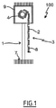
- an installation 100 comprising a closing, screening or solar protection device 3 in accordance with one embodiment of the invention, installed in a building comprising an opening 1, window or door.
- This installation 100 is equipped with a screen 2 belonging to the device for closing, concealment or concealment 3, in particular a motorized rolling shutter.
- the closing, shading or solar protection device 3 is hereinafter referred to as the "shading device".
- the concealment device 3 comprises the screen 2.
- the device for closing, screening or sun protection 3 can be a rolling shutter, a blind made of fabric or with adjustable slats, or even a rolling gate.
- the present invention applies to all types of concealment device.
- the installation 100 includes the concealment device 3.
- the screening device 3 comprises a winding tube 4 and a motorized drive device 5.
- the motorized drive device 5 comprises an electromechanical actuator 11 illustrated in picture 3 .
- the screen 2 is configured to be moved, in other words is moved, by means of the motorized drive device 5.
- the screen 2 of the screening device 3 is rolled up on the winding tube 4 driven by the motorized drive device 5.
- the screen 2 is movable between a rolled up position, in particular high, and a unrolled position, especially low.
- the screen 2 can be rolled up on the rolling tube 4.
- the rolling tube 4 is arranged so as to be driven in rotation by the electromechanical actuator 11.
- the concealment device 3 comprises a box 9.
- the screen 2 is arranged, in other words is configured to be arranged, at least partly inside the trunk 9, in an assembled configuration of the concealment device 3.
- the screen 2 of the concealment device 3 is a closing, concealment and/or solar protection screen, winding and unwinding around the winding tube 4, the internal diameter of which is greater than the external diameter of the electromechanical actuator 11, so that the electromechanical actuator 11 can be inserted into the winding tube 4, when assembling the occultation device 3.
- the motorized drive device 5 comprises the electromechanical actuator 11, in particular of the tubular type.
- the concealment device 3 includes the winding tube 4.
- the screen 2 can be rolled up and unrolled on the rolling tube 4.
- the electromechanical actuator 11 is inserted into the rolling tube 4.
- the concealment device 3 further comprises two side slides 6.
- Each side slide 6 comprises a groove 41.
- Each groove 41 of one of the side slides 6 cooperates, in other words is configured to cooperate, with an edge side 2a of the screen 2, in the assembled configuration of the concealment device 3, so as to guide the screen 2, during the movement, in particular the winding and unwinding, of the screen 2, in particular around the winding tube 4.
- the roller shutter which forms the concealment device 3
- the roller shutter comprises an apron comprising horizontal slats hinged to each other, forming the screen 2 of the roller shutter 3, and guided by the two side slides 6. These blades are contiguous when the apron 2 of the roller shutter 3 reaches its low unrolled position.
- the rolled up position corresponds to the bearing of a final end slat 8, for example L-shaped, of the apron 2 of the roller shutter 3 against an edge of the box 9 of the rolling shutter 3 or when the final end slat 8 stops in a programmed top end-of-travel position.
- the unrolled low position corresponds to the resting of the final end slat 8 of the apron 2 of the roller shutter 3 against a threshold 7 of the opening 1 or to the stopping of the final end slat 8 in a programmed bottom end position.
- the first slat of the roller shutter 3, opposite the final end slat 8, is connected to the winding tube 4 by means of at least one articulation 10, in particular a strap-shaped attachment piece.
- the winding tube 4 is arranged inside the box 9 of the roller shutter 3.
- the apron 2 of the roller shutter 3 is rolled up and unrolled around the winding tube 4 and is housed at least in part at the trunk interior 9.
- the trunk 9 is arranged above the opening 1, or even in the upper part of the opening 1.
- the motor drive device 5 is controlled by a control unit.
- the control unit can be, for example, a local control unit 12.
- the local control unit 12 can be connected by wired or wireless link with a central control unit 13.
- the central control unit 13 controls the local control unit 12, as well as other similar local control units and distributed throughout the building.
- the motorized drive device 5 is preferably configured to execute the movement commands, in particular for unwinding or winding, of the screen 2 of the concealment device 3, which can be issued, in particular, by the unit local control unit 12 or the central control unit 13.
- the installation 100 comprises either the local control unit 12, or the central control unit 13, or the local control unit 12 and the central control unit 13.
- the motorized drive device 5 including the electromechanical actuator 11, belonging to the installation 100 of the figure 1 and 2 .
- the electromechanical actuator 11 includes an electric motor 16.
- the electric motor 16 comprises a rotor and a stator, not shown and positioned coaxially around the axis of rotation X, which is also the axis of rotation of the winding tube 4 in the mounted configuration of the device. motor drive 5.
- Means for controlling the electromechanical actuator 11, allowing the movement of the screen 2 of the concealment device 3, consist of at least one electronic control unit 15.
- This electronic control unit 15 is capable of putting into operation the electric motor 16 of the electromechanical actuator 11 and, in particular, to allow the electric power supply to the electric motor 16.
- the electronic control unit 15 controls, in particular, the electric motor 16, so as to open or close the screen 2, as described previously.
- the control means of the electromechanical actuator 11 comprise hardware and/or software means.
- the hardware means may comprise at least one microcontroller 31, illustrated in picture 3 .
- the motorized drive device 5 comprises the electronic control unit 15.
- the electronic control unit 15 is electrically connected to the electric motor 16.
- the electronic control unit 15 is placed inside the box 9, in the Assembled configuration of the muting device 3.
- the electronic control unit 15 further comprises a first communication module 27, as illustrated in picture 3 , in particular for receiving control commands, the control commands being transmitted by a command transmitter, such as the local control unit 12 or the central control unit 13, these commands being intended to control the device motor drive 5.
- a command transmitter such as the local control unit 12 or the central control unit 13
- the first communication module 27 of the electronic control unit 15 is of the wireless type.
- the first communication module 27 is configured to receive radio control commands.
- the motorized drive device 5 comprises a radio antenna 25.
- the radio antenna 25 is electrically connected to the electronic control unit 15 and, more particularly, to the first communication module 27.
- the first communication module 27 can also allow the reception of control commands transmitted by wired means.
- the electronic control unit 15, the local control unit 12 and/or the central control unit 13 can be in communication with a remote weather station outside the building, including, in particular, one or more sensors that can be configured to determine, for example, a temperature, a luminosity or even a wind speed.
- the electronic control unit 15, the local control unit 12 and/or the central control unit 13 can also be in communication with a server 28, so as to control the electromechanical actuator 11 according to data made available remotely via a communication network, in particular an Internet network that can be connected to the server 28.
- a communication network in particular an Internet network that can be connected to the server 28.
- the electronic control unit 15 can be controlled from the local 12 and/or central 13 control unit.
- the local 12 and/or central 13 control unit is provided with a control keyboard.
- the control keyboard of the local 12 or central 13 control unit comprises one or more selection elements 14 and, optionally, one or more display elements 34.
- the selection elements can be push buttons or sensitive keys
- the display elements can be light-emitting diodes, an LCD display (acronym of the Anglo-Saxon term “Liquid Crystal Display”) or TFT (acronym of the Anglo-Saxon term “Thin Film Transistor”).
- the selection and display elements can also be produced by means of a touch screen.
- the local 12 and/or central 13 control unit comprises at least one second communication module 36.
- the second communication module 36 of the local 12 or central 13 control unit is configured to transmit, in other words sends, control commands, by wireless means, in this case radioelectric, and, possibly, by wired means.
- the second communication module 36 of the local 12 or central 13 control unit can also be configured to receive, in other words receive, control commands, in particular via the same means.
- the second communication module 36 of the local 12 or central 13 control unit is configured to communicate, in other words communicates, with the first communication module 27 of the electronic control unit 15.
- the second communication module 36 of the local 12 or central 13 control unit exchanges control commands with the first communication module 27 of the electronic control unit 15, either unidirectionally or bidirectionally.
- the local control unit 12 is a control point, which can be fixed or mobile.
- a fixed control point can be a control box control intended to be fixed on a facade of a wall of the building or on a face of a fixed frame of a window or a door.
- a nomadic control point can be a remote control, a smart phone or a tablet.
- the local 12 and/or central 13 control unit further comprises a controller 35.
- the motorized drive device 5, in particular the electronic control unit 15, is preferably configured to execute movement control commands, in particular closing as well as opening, of the screen 2 of the device. occultation 3. These commands can be issued, in particular, by the local control unit 12 or by the central control unit 13.
- the motorized drive device 5 can be controlled by the user, for example by receiving a control command corresponding to a press on the or one of the selection elements 14 of the local control unit 12 or center 13.
- the motorized drive device 5 can also be controlled automatically, for example by receiving a control command corresponding to at least one signal coming from at least one sensor and/or to a signal coming from a clock of the electronic control unit 15, in particular the microcontroller 31.
- the sensor and/or the clock can be integrated into the local control unit 12 or the central control unit 13.
- the electromechanical actuator 11 comprises a casing 17, in particular tubular.
- the electric motor 16 is mounted inside the casing 17, in particular in an assembled configuration of the electromechanical actuator 11.
- the casing 17 of the electromechanical actuator 11 is of cylindrical shape, in particular of revolution around the axis of rotation X.
- the casing 17 is made of a metallic material.
- the material of the housing of the electromechanical actuator is not limiting and can be different. It may be, in particular, a plastic material.
- the electromechanical actuator 11 further comprises a reduction gear 19 and an output shaft 20.
- the electromechanical actuator 11 further comprises a brake 29.
- the brake 29 can be a spring brake, a cam brake, a magnetic brake or an electromagnetic brake.
- the brake 29 is configured to be arranged, in other words is arranged between the electric motor 16 and the reducer 19, that is to say at the output of the electric motor 16.
- the brake 29 is configured to be arranged, in other words is arranged, between the electronic control unit 15 and the electric motor 16, in other words at the input of the electric motor 16, between the reducer 19 and the output shaft 20, in other words at the output of the reducer 19, or between two reduction stages of the reducer 19.
- the electric motor 16, the brake 29 and the reducer 19 are configured to be mounted, in other words are mounted, inside the casing 17 of the electromechanical actuator 11, in the assembled configuration of the electromechanical actuator 11.
- the electromechanical actuator 11 can also include an end-of-travel and/or obstacle detection device, which can be mechanical or electronic.
- the winding tube 4 is driven in rotation around the axis of rotation X and the casing 17 of the electromechanical actuator 11 while being supported via two pivot links.
- the first pivot connection is made at a first end of the winding tube 4 by means of a crown 30 inserted around a first end 17a of the casing 17 of the electromechanical actuator 11.
- the crown 30 thus makes it possible to make a landing.
- the second pivot link is made at a second end of the winding tube 4, not visible in this figure.
- the electromechanical actuator 11 comprises a torque support 21.
- the torque support 21 projects at the level of the first end 17a of the casing 17 of the electromechanical actuator 11, in particular the end 17a of the casing 17 receiving the crown 30.
- the torque support 21 of the electromechanical actuator 11 thus makes it possible to fix the electromechanical actuator 11 to a frame 23, in particular to a cheek of the trunk 9.
- the torque support 21 of the electromechanical actuator 11 can make it possible to close the first end 17a of the casing 17.
- the torque support 21 of the electromechanical actuator 11 can make it possible to support the electronic control unit 15.
- the electronic control unit 15 can be supplied with electrical energy by means of the electrical supply cable 18.
- the electronic control unit 15 is thus arranged, in other words integrated, inside the casing 17 of the electromechanical actuator 11.
- the electronic control unit 15 is arranged outside the casing 17 of the electromechanical actuator 11 and, in particular, mounted on the box 9 or in the torque support 21.
- the output shaft 20 of the electromechanical actuator 11 is arranged inside the winding tube 4 and at least partly outside the casing 17 of the electromechanical actuator 11.
- one end of the output shaft 20 projects relative to the casing 17 of the electromechanical actuator 11, in particular relative to a second end 17b of the casing 17 opposite the first end 17a.
- the output shaft 20 of the electromechanical actuator 11 is configured to rotate a connecting element 22 connected to the winding tube 4.
- the connecting element 22 is made in the form of a wheel.
- the electric motor 16 and the reducer 19 rotate the output shaft 20.
- the output shaft 20 of the electromechanical actuator 11 rotates the winding tube 4 via the connecting element 22.
- the winding tube 4 rotates the screen 2 of the screening device 3, so as to open or close the opening 1.
- the concealment device 3 further comprises an electric power supply device 39, visible to the figure 6 and 7 .
- the electromechanical actuator 11 is electrically connected to the electrical power supply device 39.
- the electrical energy supply device 39 comprises at least one battery 24.
- the electronic control unit 15 and the electric motor 16 and, more particularly, the electromechanical actuator 11 are supplied, in other words configured to be supplied, with energy electricity by means of the battery 24.
- the battery 24 can thus be arranged inside or outside the box 9.
- the battery 24 can also be arranged inside the winding tube 4, while being outside the casing 17.
- battery 24 can also be arranged inside the casing 17.
- the electromechanical actuator 11 comprises an electrical power cable 18 allowing it to be supplied with electrical energy, in particular from the electronic control unit 15 and from the electric motor 16, in particular from the battery 24.
- the battery 24 is electrically connected directly to the electronic control unit 15, in particular by the power supply cable 18.
- the battery 24 is of the rechargeable type.
- the battery 24 comprises one or more storage elements of energy.
- the energy storage elements of the battery 24 can be, in particular, rechargeable accumulators or batteries.
- the electrical energy supply device 39 further comprises at least one photovoltaic panel 40.
- the photovoltaic panel 40 forms an external electrical energy supply source.
- the battery 24 is supplied with electrical energy, in other words is configured to be supplied with electrical energy, by means of the photovoltaic panel 40.
- the motorized drive device 5 and, in particular, the electronic control unit 15, comprises charging elements configured to charge the battery 24 from the electrical energy supplied by the photovoltaic panel 40.
- the electronic control unit 15 comprises a single electronic card.
- the electronic card is configured to control the electric motor 16, to allow the recharging of the battery 24 and, possibly, to access parameter setting and/or configuration functions of the electromechanical actuator 11, by means of elements selection and, possibly, display, not shown.
- the battery charging elements 24 can be arranged at the level of the electronic card.
- the electronic control unit 15 comprises a first electronic card and a second electronic card.
- the first electronic card is configured to control the electric motor 16.
- the second electronic card is configured to allow the recharging of the battery 24 and, possibly, to access parameter setting and/or configuration functions of the electromechanical actuator 11, by means of selection and, possibly, display elements, not shown.
- the battery charging elements 24 can be arranged at the level of the second electronic card.
- the concealment device 3 further comprises a support 26.
- the support 26 comprises at least one housing 32.
- the support 26 is arranged outside the box 9, in the assembled configuration of the concealment device 3.
- the radio antenna 25 is arranged partly inside the housing 32 of the support 26, in the assembled configuration of the concealment device 3.
- such a configuration of the concealment device 3 makes it possible to maintain the radio antenna 25 in position outside the trunk 9, so as to guarantee satisfactory performance of reception, transmission or reception and transmission of radio signals, while respecting one or more conditions for positioning the motorized drive device 5 with respect to the concealment device 3.
- a condition of placement is, in particular, to place a part of the radio antenna 25 at a minimum distance D from a metallic surface, which can be, for example, of the order of ten millimeters.
- Another installation condition may be to prevent the radio antenna 25 from being folded back on itself.
- the radioelectric antenna 25 is held in position, in other words is channeled, partly outside the trunk 9, following the insertion of a part of the latter at the interior of housing 32.
- the distance D corresponds to a determined minimum distance between a base 26c of the support 26 and a wall 32a of the housing 32 of the support 26.
- the part of the radio antenna 25 introduced into the housing 32 of the support 26 is necessarily arranged, with respect to a surface 37, at a distance greater than or equal to the distance D.
- the surface 37 is a surface for fixing the support 26, in the assembled configuration of the concealment device 3, in particular in the installation 100.
- the surface 37 can be defined by a wall M of the building, a wall of the trunk 9, a wall of one of the side rails 6 or part of a frame of a window or a door.
- the support 32 makes it possible to protect the radioelectric antenna 25, in particular the part of the latter located outside the trunk 9, from any degradation, which may be due, in particular, to a tearing or a cut. , which can be caused, for example, by a displacement of the screen 2 by means of the motorized drive device 5 or by a closing of a sash of a window or a door with respect to a fixed frame.
- the support 26 therefore makes it possible, following the insertion of a part of the radioelectric antenna 25 inside the housing 32 of the support 26, to disengage the latter from the lateral slideways 6 of the concealment device 3 intended for guiding of the screen 2, when the screen 2 is moved, and to disengage it from the uprights of a window or a door, when the screening device 3 is placed on a wall M of the building.
- the support 26 makes it possible to improve the aesthetics of the concealment device 3 by masking the part of the radioelectric antenna 25 located outside the trunk 9, so as to prevent the radioelectric antenna 25 from coming out an opening 33 made in the trunk 9 while being left free outside thereof.
- the support 26 can be installed, in other words is configured to be installed, on different elements of the occultation device 3 or of the building receiving the occultation device 3.
- the support 26, in particular the base 26c of the support 26, is fixed on the surface 37.
- the support 26, in particular the base 26c of the support 26, is fixed to the surface 37, by means of an adhesive 38.
- the support 26 is installed, in other words is configured to be installed, on the surface 37 without the use of a tool.
- the housing 32 of the support 26 has a rectilinear shape, in a longitudinal direction.
- the shape of the housing 32 of the support 26 makes it possible to prevent the radio antenna 25 from folding back on itself.
- the trunk 9 includes the opening 33.
- the radio antenna 25 is configured to extend, in other words extends, from the electronic control unit 15 to the interior of the housing. 32 of support 26 passing through opening 33 of trunk 9.
- the support 26 is made of a plastic material.
- the plastic material of the support 26 can be a thermoplastic polymer, such as, for example, a polyvinyl chloride, or an elastomer.
- the support 26 is fixed to the trunk 9.
- the surface 37 is a wall of the trunk 9.
- the support 26 is fixed to one of the side slides 6.
- the surface 37 is a wall of one of the side slides 6.
- the support 26 is fixed to a wall M of the building.
- the surface 37 is the wall M of the building.
- the support 26 comprises fixing elements, not shown, in particular at least two tabs each comprising a passage hole.
- Each passage hole is configured to receive a fixing screw which is screwed into a plug fixed in the wall M of the building.
- the housing 32 of the support 26 emerges at each of the two ends 26a, 26b of the support 26.
- the support 26 comprises two openings 42, only one of which is shown in figure 8 .
- Each opening 42 emerges and is connected to housing 32 of support 26.
- the radio antenna 25 can be introduced inside the housing 32 of the support 26 by one or the other of the ends 26a, 26b of the support 26.
- the support 26 is reversible and therefore has no mounting direction with respect to the surface 37.
- the performance of receiving and/or transmitting radio signals by means of the radio antenna 25 is improved, since the radio signals can leave the housing 32 or enter the housing 32 without being disturbed by a wall of closure at the level of the openings 42 of the support 26.
- the radio antenna 25 is made in the form of a wire, in particular by means of a coaxial cable.
- such a coaxial cable comprises at least one central core, a dielectric material, in other words an insulating material, a shield and an insulating outer sheath, not shown.
- the central core is surrounded by the dielectric material.
- the dielectric material is surrounded by the shield. Further, the shield is surrounded by the insulating outer sheath.
- the central core is an electrical conductor comprising one or more strands.
- the central core can be made, for example, of copper, tinned or silvered copper, or copper-plated steel.
- the shielding can be made by a conductive braid, which can be, for example, copper.
- part of the radio antenna 25 is devoid of at least the conductive braid, in particular by stripping the coaxial cable.
- This part of the radio antenna 25 corresponds to a so-called active part, not shown.
- the part of the radio antenna 25 arranged inside the housing 32 of the support 26 corresponds at least to the active part of the radio antenna 25.
- the active part of the radioelectric antenna 25 has a length corresponding to a quarter wavelength of the transmission and/or reception frequency of radioelectric signals.
- the active part of the radio antenna 25 may have a length of the order of 86 millimeters when the frequency of transmission and/or reception of radio signals is of the order of 868 MHz , of the order of 173 millimeters when the frequency of transmission and/or reception of radioelectric signals is of the order of 433 MHz and of the order of 30.6 millimeters when the frequency of transmission and/or reception of radio signals is of the order of 2.4 GHz.
- the transmission and/or reception frequency of radioelectric signals may be different and within a range extending between 400 MHz and 4 GHz, and may take, in particular, values of the order of 433 MHz, 868 MHz or 2.4GHz.
- the active part of the radio antenna 25 can be made by means of a printed circuit board, the printed circuit board being configured to be placed inside the housing 32 of the support 26 and having a printed transmission line, in particular a printed quarter-wave line.
- the active part of the radio antenna 25 can be made by means of a metal wire, the metal wire being electrically connected to the remaining part of the radio antenna 25, in particular by means of an electrical connector or, for example, by crimping.
- the configuration of the concealment device makes it possible to maintain the radio antenna in position outside the trunk, so as to guarantee satisfactory performance of reception, transmission or reception and transmission of radioelectric signals, while complying with one or more conditions for positioning the motorized drive device with respect to the concealment device.
- the electronic control unit 15 and the electric motor 16 and, more particularly, the electromechanical actuator 11 are supplied with electrical energy by a mains electrical supply network.
- the electromechanical actuator 11 comprises an electric power cable allowing it to be supplied with electric power from the mains power supply network.
Landscapes
- Engineering & Computer Science (AREA)
- Structural Engineering (AREA)
- Architecture (AREA)
- Civil Engineering (AREA)
- Operating, Guiding And Securing Of Roll- Type Closing Members (AREA)
- Power-Operated Mechanisms For Wings (AREA)
Abstract
Un dispositif d'occultation (3) comprend un coffre (9), un écran (2) et un dispositif d'entraînement motorisé. Le dispositif d'entraînement motorisé comprend un actionneur électromécanique, une unité électronique de contrôle et une antenne radioélectrique (25). L'actionneur électromécanique comprend un moteur électrique. L'unité électronique de contrôle est reliée électriquement au moteur électrique. L'unité électronique de contrôle est disposée à l'intérieur du coffre (9). L'antenne radioélectrique (25) est reliée électriquement à l'unité électronique de contrôle. Le dispositif d'occultation (3) comprend, en outre, un support (26). Le support (26) comprend un logement (32). Le support (26) est disposé à l'extérieur du coffre (9). L'antenne radioélectrique (25) est disposée en partie à l'intérieur du logement (32) du support (26).A screening device (3) comprises a box (9), a screen (2) and a motor drive device. The motor drive device comprises an electromechanical actuator, an electronic control unit and a radio antenna (25). The electromechanical actuator includes an electric motor. The electronic control unit is electrically connected to the electric motor. The electronic control unit is arranged inside the trunk (9). The radio antenna (25) is electrically connected to the electronic control unit. The concealment device (3) further comprises a support (26). The support (26) includes a housing (32). The support (26) is arranged outside the box (9). The radio antenna (25) is arranged partly inside the housing (32) of the support (26).
Description
La présente invention concerne un dispositif d'occultation comprenant un coffre, un écran et un dispositif d'entraînement motorisé. L'écran est entraîné en déplacement par un actionneur électromécanique du dispositif d'entraînement motorisé disposé à l'intérieur du coffre.The present invention relates to a screening device comprising a box, a screen and a motorized drive device. The screen is driven in displacement by an electromechanical actuator of the motorized drive device disposed inside the trunk.
De manière générale, la présente invention concerne le domaine des dispositifs d'occultation comprenant un dispositif d'entraînement motorisé mettant en mouvement un écran, entre au moins une première position et au moins une deuxième position.In general, the present invention relates to the field of screening devices comprising a motorized drive device that sets a screen in motion between at least a first position and at least a second position.
Un dispositif d'entraînement motorisé comprend un actionneur électromécanique d'un élément mobile de fermeture, d'occultation ou de protection solaire tel qu'un volet, une porte, une grille, un store ou tout autre matériel équivalent, appelé par la suite écran.A motorized drive device comprises an electromechanical actuator for a movable closing, shading or solar protection element such as a shutter, a door, a grille, a blind or any other equivalent material, hereinafter called a screen. .
On connaît déjà des dispositifs d'occultation comprenant un coffre, un écran et un dispositif d'entraînement motorisé, comme par exemple dans le document
Cependant, ces dispositifs d'occultation présentent l'inconvénient de faire passer l'antenne radioélectrique au travers d'une ouverture du coffre et de laisser l'antenne radioélectrique libre à l'extérieur du coffre, c'est-à-dire sans être maintenue en position par rapport au dispositif d'occultation.However, these concealment devices have the disadvantage of passing the radio antenna through an opening in the trunk and of leaving the radio antenna free outside the trunk, that is to say without being held in position relative to the concealment device.
Ainsi, une partie de l'antenne radioélectrique peut être en contact avec une surface métallique.Thus, part of the radio antenna can be in contact with a metallic surface.
Par conséquent, une performance de réception, d'émission ou de réception et d'émission de signaux radioélectriques par l'intermédiaire de l'antenne radioélectrique peut être dégradée.Therefore, a performance of receiving, transmitting, or receiving and transmitting radio signals through the radio antenna may be degraded.
En outre, l'antenne radioélectrique peut être endommagée lors du déplacement de l'écran, puisque celle-ci peut être entraînée par l'écran et ce qui peut provoquer une coupure ou un arrachement de l'antenne radioélectrique par rapport à l'unité électronique de contrôle.In addition, the radio antenna can be damaged when moving the screen, since it can be dragged by the screen and this can cause the radio antenna to be cut or torn from the unit. control electronics.
Par ailleurs, l'antenne radioélectrique peut être repliée sur elle-même, étant donné que celle-ci n'est pas maintenue en position à l'extérieur du coffre.Furthermore, the radio antenna can be folded back on itself, given that the latter is not held in position outside the trunk.
Par conséquent, une performance de réception, d'émission ou de réception et d'émission de signaux radioélectriques par l'intermédiaire de l'antenne radioélectrique peut être dégradée.Therefore, a performance of receiving, transmitting, or receiving and transmitting radio signals through the radio antenna may be degraded.
On connaît également le document
On connaît également le document
La présente invention a pour but de résoudre les inconvénients précités et de proposer un dispositif d'occultation comprenant un dispositif d'entraînement motorisé équipé d'une antenne radioélectrique permettant de maintenir en position l'antenne radioélectrique à l'extérieur du coffre, de sorte à garantir une performance de réception, d'émission ou de réception et d'émission de signaux radioélectriques en respectant une ou plusieurs conditions de mise en place du dispositif d'entraînement motorisé par rapport au dispositif d'occultation.The object of the present invention is to solve the aforementioned drawbacks and to propose a concealment device comprising a motorized drive device equipped with a radioelectric antenna making it possible to maintain the radioelectric antenna in position outside the trunk, so to guarantee a performance of reception, transmission or reception and transmission of radioelectric signals while respecting one or more conditions of installation of the motorized drive device with respect to the occultation device.
A cet égard, la présente invention vise un dispositif d'occultation, le dispositif d'occultation comprenant au moins :
- un coffre,
- un écran, l'écran étant disposé au moins en partie à l'intérieur du coffre,
- dans une configuration assemblée du dispositif d'occultation, et
- un dispositif d'entraînement motorisé, l'écran étant configuré pour être
- déplacé au moyen du dispositif d'entraînement motorisé,
- un actionneur électromécanique, l'actionneur électromécanique comprenant au moins un moteur électrique,
- une unité électronique de contrôle, l'unité électronique de contrôle étant reliée électriquement au moteur électrique, l'unité électronique de contrôle étant disposée à l'intérieur du coffre, dans la configuration assemblée du dispositif d'occultation, et
- une antenne radioélectrique, l'antenne radioélectrique étant reliée électriquement à l'unité électronique de contrôle.
- a safe,
- a screen, the screen being arranged at least partly inside the trunk,
- in an assembled configuration of the concealment device, and
- a motorized training device, the screen being configured to be
- moved by means of the motorized drive device,
- an electromechanical actuator, the electromechanical actuator comprising at least one electric motor,
- an electronic control unit, the electronic control unit being electrically connected to the electric motor, the electronic control unit being arranged inside the boot, in the assembled configuration of the concealment device, and
- a radio antenna, the radio antenna being electrically connected to the electronic control unit.
Selon l'invention, le dispositif d'occultation comprend, en outre, un support, le support comprenant au moins un logement, le support étant disposé à l'extérieur du coffre, dans la configuration assemblée du dispositif d'occultation. En outre, l'antenne radioélectrique est disposée en partie à l'intérieur du logement du support, dans la configuration assemblée du dispositif d'occultation.According to the invention, the concealment device further comprises a support, the support comprising at least one housing, the support being arranged outside the trunk, in the assembled configuration of the concealment device. In addition, the radio antenna is arranged partly inside the housing of the support, in the assembled configuration of the concealment device.
Ainsi, une telle configuration du dispositif d'occultation permet de maintenir en position l'antenne radioélectrique à l'extérieur du coffre, de sorte à garantir une performance satisfaisante de réception, d'émission ou de réception et d'émission de signaux radioélectriques, tout en respectant une ou plusieurs conditions de mise en place du dispositif d'entraînement motorisé par rapport au dispositif d'occultation.Thus, such a configuration of the concealment device makes it possible to maintain the radio antenna in position outside the trunk, so as to guarantee satisfactory performance of reception, transmission or reception and transmission of radio signals, while respecting one or more conditions for positioning the motorized drive device with respect to the screening device.
Une condition de mise en place est, notamment, de disposer une partie de l'antenne radioélectrique à une distance minimale d'une surface métallique, pouvant être, par exemple, de l'ordre de dix millimètres. Une autre condition de mise en place peut être d'empêcher de replier l'antenne radioélectrique sur elle-même.One installation condition is, in particular, to place part of the radio antenna at a minimum distance from a metal surface, which may be, for example, of the order of ten millimeters. Another installation condition may be to prevent the radio antenna from being folded back on itself.
De cette manière, l'antenne radioélectrique est maintenue en position, autrement dit est canalisée, en partie à l'extérieur du coffre au moyen du support, suite à l'insertion d'une partie de celle-ci à l'intérieur du logement du support.In this way, the radio antenna is held in position, in other words is channeled, partly outside the trunk by means of the support, following the insertion of part of the latter inside the housing of the medium.
En outre, le support permet de protéger l'antenne radioélectrique, en particulier la partie de celle-ci située à l'extérieur du coffre, de toute dégradation, pouvant être due, notamment, à un arrachement ou à une coupure, pouvant être provoqué, par exemple, par un déplacement de l'écran au moyen du dispositif d'entraînement motorisé ou par une fermeture d'un ouvrant d'une fenêtre ou d'une porte par rapport à un cadre dormant. Le support permet donc, suite à l'insertion d'une partie de l'antenne radioélectrique à l'intérieur du logement du support, de dégager celle-ci de coulisses latérales du dispositif d'occultation destinées au guidage de l'écran, lors d'un déplacement de l'écran, et de dégager celle-ci de montants d'une fenêtre ou d'une porte, lors de la pose du dispositif d'occultation sur un mur d'un bâtiment.In addition, the support makes it possible to protect the radioelectric antenna, in particular the part of the latter located outside the boot, from any degradation, which may be due, in particular, to tearing or cutting, which may be caused , for example, by moving the screen by means of the motorized drive device or by closing a sash of a window or a door with respect to a fixed frame. The support therefore makes it possible, following the insertion of a part of the radioelectric antenna inside the housing of the support, to disengage the latter from the side slides of the concealment device intended for guiding the screen, when of a movement of the screen, and to release it from the uprights of a window or a door, during the installation of the concealment device on a wall of a building.
Par ailleurs, le support permet d'améliorer l'esthétisme du dispositif d'occultation en masquant la partie de l'antenne radioélectrique située à l'extérieur du coffre, de sorte à éviter que l'antenne radioélectrique ne sorte d'une ouverture ménagée dans le coffre et soit laissée libre à l'extérieur de celui-ci.Furthermore, the support makes it possible to improve the aesthetics of the concealment device by masking the part of the radioelectric antenna located outside the boot, so as to prevent the radioelectric antenna from coming out of an opening provided in the trunk and is left free outside it.
En outre, le support peut être installé, autrement dit est configuré pour être installé, sur différents éléments du dispositif d'occultation ou d'un bâtiment recevant le dispositif d'occultation.Furthermore, the support can be installed, in other words is configured to be installed, on different elements of the screening device or of a building receiving the screening device.
Selon une caractéristique avantageuse de l'invention, le support est fixé sur le coffre.According to an advantageous characteristic of the invention, the support is fixed to the trunk.
Selon une autre caractéristique avantageuse de l'invention, le dispositif d'occultation comprend, en outre, deux coulisses latérales, chaque coulisse latérale comprenant une gorge, chaque gorge de l'une des coulisses latérales coopérant avec un bord latéral de l'écran, dans la configuration assemblée du dispositif d'occultation de sorte à guider l'écran, lors du déplacement de l'écran.According to another advantageous characteristic of the invention, the concealment device further comprises two side slides, each side slide comprising a groove, each groove of one of the side slides cooperating with a side edge of the screen, in the assembled configuration of the concealment device so as to guide the screen, when moving the screen.
En variante, le support est fixé sur l'une des coulisses latérales.Alternatively, the support is fixed to one of the side slides.
En variante, le support est fixé sur un mur d'un bâtiment.Alternatively, the support is fixed to a wall of a building.
Selon une autre caractéristique avantageuse de l'invention, le support est fixé sur une surface au moyen d'un adhésif.According to another advantageous characteristic of the invention, the support is fixed to a surface by means of an adhesive.
Selon une autre caractéristique avantageuse de l'invention, le coffre comprend une ouverture. En outre, l'antenne radioélectrique est configurée pour s'étendre à partir de l'unité électronique de contrôle jusqu'à l'intérieur du logement du support en passant au travers de l'ouverture du coffre.According to another advantageous characteristic of the invention, the trunk comprises an opening. Further, the radio antenna is configured to extend from from the electronic control unit to the interior of the support housing, passing through the boot opening.
Selon une autre caractéristique avantageuse de l'invention, l'antenne radioélectrique est réalisée sous la forme d'un fil.According to another advantageous characteristic of the invention, the radio antenna is made in the form of a wire.
Selon une autre caractéristique avantageuse de l'invention, le support est réalisé dans une matière plastique.According to another advantageous characteristic of the invention, the support is made of a plastic material.
Selon une autre caractéristique avantageuse de l'invention, le dispositif d'occultation comprend un dispositif d'alimentation en énergie électrique. Le dispositif d'alimentation en énergie électrique comprend au moins une batterie. En outre, l'unité électronique de contrôle et le moteur électrique sont alimentés en énergie électrique au moyen de la batterie.According to another advantageous characteristic of the invention, the concealment device comprises an electrical power supply device. The electrical energy supply device comprises at least one battery. Furthermore, the electronic control unit and the electric motor are supplied with electrical energy by means of the battery.
Selon une autre caractéristique avantageuse de l'invention, le dispositif d'alimentation en énergie électrique comprend, en outre, au moins un panneau photovoltaïque. En outre, la batterie est alimentée en énergie électrique au moyen du panneau photovoltaïque.According to another advantageous characteristic of the invention, the electrical energy supply device further comprises at least one photovoltaic panel. In addition, the battery is supplied with electrical energy by means of the photovoltaic panel.
Selon une autre caractéristique avantageuse de l'invention, le logement du support est débouchant à chacune des deux extrémités du support.According to another advantageous characteristic of the invention, the housing of the support opens out at each of the two ends of the support.
Selon une autre caractéristique avantageuse de l'invention, la partie de l'antenne radioélectrique disposée à l'intérieur du logement du support correspond au moins à une partie active de l'antenne radioélectrique.According to another advantageous characteristic of the invention, the part of the radio antenna arranged inside the housing of the support corresponds at least to an active part of the radio antenna.
Selon une autre caractéristique avantageuse de l'invention, le logement du support présente une forme rectiligne, selon une direction longitudinale.According to another advantageous characteristic of the invention, the housing of the support has a rectilinear shape, in a longitudinal direction.
Selon une autre caractéristique avantageuse de l'invention, le support comprend, en outre, une base. Le logement comprend une paroi. Une distance minimale est déterminée entre la base du support et la paroi du logement du support. En outre, la base du support est fixée sur une surface.According to another advantageous characteristic of the invention, the support further comprises a base. The housing includes a wall. A minimum distance is determined between the base of the bracket and the wall of the bracket housing. In addition, the base of the stand is fixed on a surface.
D'autres particularités et avantages de l'invention apparaîtront encore dans la description ci-après.Other features and advantages of the invention will appear further in the description below.
Aux dessins annexés, donnés à titre d'exemples non limitatifs :
- [
Fig 1 ] lafigure 1 est une vue schématique en coupe transversale d'une installation comprenant un dispositif d'occultation conforme à un mode de réalisation de l'invention ; - [
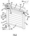
Fig 2 ] lafigure 2 est une vue schématique en perspective de l'installation illustrée à lafigure 1 ; - [
Fig 3 ] lafigure 3 est une vue schématique en coupe axiale et partielle de l'installation illustrée auxfigures 1 et 2 , montrant un actionneur électromécanique de l'installation ; - [
Fig 4 ] lafigure 4 est une vue schématique en perspective et partielle de l'installation telle qu'illustrée auxfigures 1 à 3 , montrant une antenne radioélectrique et un support de celle-ci, selon un premier exemple de positionnement dans l'installation, où un tube d'enroulement d'un écran a été ôté ; - [
Fig 5 ] lafigure 5 est une vue schématique de côté de l'installation telle qu'illustrée à lafigure 4 , montrant l'antenne radioélectrique et le support de celle-ci selon le premier exemple de positionnement dans l'installation, où une joue d'un coffre a été ôtée ; - [
Fig 6 ] lafigure 6 est une vue analogue à lafigure 4 , selon un autre angle de vue, illustrant l'antenne radioélectrique et le support, selon un deuxième exemple de positionnement dans l'installation, où le tube d'enroulement et l'écran ont été ôtés ; - [
Fig 7 ] lafigure 7 est une vue analogue auxfigures 4 et 6 , selon un autre angle de vue, illustrant l'antenne radioélectrique et le support, selon un troisième exemple de positionnement dans l'installation, où le tube d'enroulement de l'écran a été ôté ; et - [
Fig 8 ] lafigure 8 est une vue schématique en perspective du support illustré auxfigures 4 à 7 .
- [
Fig 1 ] thefigure 1 is a schematic cross-sectional view of an installation comprising a screening device according to one embodiment of the invention; - [
Fig 2 ] thepicture 2figure 1 ; - [
Fig.3 ] thepicture 3figure 1 and2 , showing an actuator electromechanical installation; - [
Fig 4 ] thefigure 4 is a schematic partial perspective view of the installation as illustrated infigures 1 to 3 , showing a radio antenna and a support thereof, according to a first example of positioning in the installation, where a winding tube of a screen has been removed; - [
Fig.5 ] thefigure 5 is a schematic side view of the installation as shown infigure 4 , showing the radio antenna and the support thereof according to the first example of positioning in the installation, where a cheek of a trunk has been removed; - [
Fig 6 ] thefigure 6 is a view analogous tofigure 4 , from another angle of view, illustrating the radio antenna and the support, according to a second example of positioning in the installation, where the winding tube and the screen have been removed; - [
Fig 7 ] thefigure 7 is a view analogous tofigure 4 and6 , from another angle of view, illustrating the radio antenna and the support, according to a third example of positioning in the installation, where the winding tube of the screen has been removed; and - [
Fig.8 ] thefigure 8 is a schematic perspective view of the support shown infigures 4 to 7 .
On décrit tout d'abord, en référence aux
Le dispositif de fermeture, d'occultation ou de protection solaire 3 est par la suite appelé « dispositif d'occultation ». Le dispositif d'occultation 3 comprend l'écran 2.The closing, shading or
Le dispositif de fermeture, d'occultation ou de protection solaire 3 peut être un volet roulant, un store en toile ou avec des lames orientables, ou encore un portail roulant. La présente invention s'applique à tous les types de dispositif d'occultation.The device for closing, screening or
Ici, l'installation 100 comprend le dispositif d'occultation 3.Here, the
On décrit, en référence aux
Le dispositif d'occultation 3 comprend un tube d'enroulement 4 et un dispositif d'entraînement motorisé 5. Le dispositif d'entraînement motorisé 5 comprend un actionneur électromécanique 11 illustré à la
L'écran 2 est configuré pour être déplacé, autrement dit est déplacé, au moyen du dispositif d'entraînement motorisé 5.The
Ici, l'écran 2 du dispositif d'occultation 3 est enroulé sur le tube d'enroulement 4 entraîné par le dispositif d'entraînement motorisé 5. Ainsi, l'écran 2 est mobile entre une position enroulée, en particulier haute, et une position déroulée, en particulier basse. Autrement dit, l'écran 2 est enroulable sur le tube d'enroulement 4. En outre, le tube d'enroulement 4 est agencé de sorte à être entraîné en rotation par l'actionneur électromécanique 11.Here, the
Le dispositif d'occultation 3 comprend un coffre 9.The
L'écran 2 est disposé, autrement dit est configuré pour être disposé, au moins en partie à l'intérieur du coffre 9, dans une configuration assemblée du dispositif d'occultation 3.The
L'écran 2 du dispositif d'occultation 3 est un écran de fermeture, d'occultation et/ou de protection solaire, s'enroulant et se déroulant autour du tube d'enroulement 4, dont le diamètre intérieur est supérieur au diamètre externe de l'actionneur électromécanique 11, de sorte que l'actionneur électromécanique 11 peut être inséré dans le tube d'enroulement 4, lors de l'assemblage du dispositif d'occultation 3.The
Le dispositif d'entraînement motorisé 5 comprend l'actionneur électromécanique 11, en particulier de type tubulaire.The
Celui-ci permet de mettre en rotation le tube d'enroulement 4 autour d'un axe de rotation X, de sorte à déplacer, en particulier dérouler ou enrouler, l'écran 2 du dispositif d'occultation 3.This makes it possible to rotate the winding
Le dispositif d'occultation 3 comprend le tube d'enroulement 4.The
Ainsi, l'écran 2 peut être enroulé et déroulé sur le tube d'enroulement 4. Dans l'état monté, l'actionneur électromécanique 11 est inséré dans le tube d'enroulement 4.Thus, the
Avantageusement, le dispositif d'occultation 3 comprend, en outre, deux coulisses latérales 6. Chaque coulisse latérale 6 comprend une gorge 41. Chaque gorge 41 de l'une des coulisses latérales 6 coopère, autrement dit est configurée pour coopérer, avec un bord latéral 2a de l'écran 2, dans la configuration assemblée du dispositif d'occultation 3, de sorte à guider l'écran 2, lors du déplacement, en particulier de l'enroulement et du déroulement, de l'écran 2, en particulier autour du tube d'enroulement 4.Advantageously, the
De manière connue, le volet roulant, qui forme le dispositif d'occultation 3, comporte un tablier comprenant des lames horizontales articulées les unes aux autres, formant l'écran 2 du volet roulant 3, et guidées par les deux coulisses latérales 6. Ces lames sont jointives lorsque le tablier 2 du volet roulant 3 atteint sa position basse déroulée.In known manner, the roller shutter, which forms the
Dans le cas d'un volet roulant, la position haute enroulée correspond à la mise en appui d'une lame d'extrémité finale 8, par exemple en forme de L, du tablier 2 du volet roulant 3 contre un bord du coffre 9 du volet roulant 3 ou à l'arrêt de la lame d'extrémité finale 8 dans une position de fin de course haute programmée. En outre, la position basse déroulée correspond à la mise en appui de la lame d'extrémité finale 8 du tablier 2 du volet roulant 3 contre un seuil 7 de l'ouverture 1 ou à l'arrêt de la lame d'extrémité finale 8 dans une position de fin de course basse programmée.In the case of a roller shutter, the rolled up position corresponds to the bearing of a
La première lame du volet roulant 3, opposée à la lame d'extrémité finale 8, est reliée au tube d'enroulement 4 au moyen d'au moins une articulation 10, en particulier une pièce d'attache en forme de bande.The first slat of the
Le tube d'enroulement 4 est disposé à l'intérieur du coffre 9 du volet roulant 3. Le tablier 2 du volet roulant 3 s'enroule et se déroule autour du tube d'enroulement 4 et est logé au moins en partie à l'intérieur du coffre 9.The winding
De manière générale, le coffre 9 est disposé au-dessus de l'ouverture 1, ou encore en partie supérieure de l'ouverture 1.In general, the
Le dispositif d'entraînement motorisé 5 est commandé par une unité de commande. L'unité de commande peut être, par exemple, une unité de commande locale 12.The
L'unité de commande locale 12 peut être reliée en liaison filaire ou non filaire avec une unité de commande centrale 13. L'unité de commande centrale 13 pilote l'unité de commande locale 12, ainsi que d'autres unités de commande locales similaires et réparties dans le bâtiment.The
Le dispositif d'entraînement motorisé 5 est, de préférence, configuré pour exécuter les commandes de déplacement, notamment de déroulement ou d'enroulement, de l'écran 2 du dispositif d'occultation 3, pouvant être émises, notamment, par l'unité de commande locale 12 ou l'unité de commande centrale 13.The
L'installation 100 comprend soit l'unité de commande locale 12, soit l'unité de commande centrale 13, soit l'unité de commande locale 12 et l'unité de commande centrale 13.The
On décrit à présent, plus en détail et en référence à la
L'actionneur électromécanique 11 comprend un moteur électrique 16.The
Avantageusement, le moteur électrique 16 comprend un rotor et un stator, non représentés et positionnés de manière coaxiale autour de l'axe de rotation X, qui est également l'axe de rotation du tube d'enroulement 4 en configuration montée du dispositif d'entraînement motorisé 5.Advantageously, the
Des moyens de commande de l'actionneur électromécanique 11, permettant le déplacement de l'écran 2 du dispositif d'occultation 3, sont constitués par au moins une unité électronique de contrôle 15. Cette unité électronique de contrôle 15 est apte à mettre en fonctionnement le moteur électrique 16 de l'actionneur électromécanique 11 et, en particulier, à permettre l'alimentation en énergie électrique du moteur électrique 16.Means for controlling the
Ainsi, l'unité électronique de contrôle 15 commande, notamment, le moteur électrique 16, de sorte à ouvrir ou fermer l'écran 2, comme décrit précédemment.Thus, the
Les moyens de commande de l'actionneur électromécanique 11 comprennent des moyens matériels et/ou logiciels.The control means of the
A titre d'exemple nullement limitatif, les moyens matériels peuvent comprendre au moins un microcontrôleur 31, illustré à la
Le dispositif d'entraînement motorisé 5 comprend l'unité électronique de contrôle 15. L'unité électronique de contrôle 15 est reliée électriquement au moteur électrique 16. L'unité électronique de contrôle 15 est disposée à l'intérieur du coffre 9, dans la configuration assemblée du dispositif d'occultation 3.The
Avantageusement, l'unité électronique de contrôle 15 comprend, en outre, un premier module de communication 27, comme illustré à la
Le premier module de communication 27 de l'unité électronique de contrôle 15 est de type sans fil. Le premier module de communication 27 est configuré pour recevoir des ordres de commande radioélectriques.The
Le dispositif d'entraînement motorisé 5 comprend une antenne radioélectrique 25. L'antenne radioélectrique 25 est reliée électriquement à l'unité électronique de contrôle 15 et, plus particulièrement, au premier module de communication 27.The
Avantageusement, le premier module de communication 27 peut également permettre la réception d'ordres de commande transmis par des moyens filaires.Advantageously, the
L'unité électronique de contrôle 15, l'unité de commande locale 12 et/ou l'unité de commande centrale 13 peuvent être en communication avec une station météorologique déportée à l'extérieur du bâtiment, incluant, notamment, un ou plusieurs capteurs pouvant être configurés pour déterminer, par exemple, une température, une luminosité ou encore une vitesse de vent.The
L'unité électronique de contrôle 15, l'unité de commande locale 12 et/ou l'unité de commande centrale 13 peuvent également être en communication avec un serveur 28, de sorte à contrôler l'actionneur électromécanique 11 suivant des données mises à disposition à distance par l'intermédiaire d'un réseau de communication, en particulier un réseau internet pouvant être relié au serveur 28.The
L'unité électronique de contrôle 15 peut être commandée à partir de l'unité de commande locale 12 et/ou centrale 13. L'unité de commande locale 12 et/ou centrale 13 est pourvue d'un clavier de commande. Le clavier de commande de l'unité de commande locale 12 ou centrale 13 comprend un ou plusieurs éléments de sélection 14 et, éventuellement, un ou plusieurs éléments d'affichage 34.The
A titre d'exemples nullement limitatifs, les éléments de sélection peuvent être des boutons poussoirs ou des touches sensitives, les éléments d'affichage peuvent être des diodes électroluminescentes, un afficheur LCD (acronyme du terme anglo-saxon « Liquid Crystal Display ») ou TFT (acronyme du terme anglo-saxon « Thin Film Transistor »). Les éléments de sélection et d'affichage peuvent être également réalisés au moyen d'un écran tactile.By way of non-limiting examples, the selection elements can be push buttons or sensitive keys, the display elements can be light-emitting diodes, an LCD display (acronym of the Anglo-Saxon term "Liquid Crystal Display") or TFT (acronym of the Anglo-Saxon term "Thin Film Transistor"). The selection and display elements can also be produced by means of a touch screen.
L'unité de commande locale 12 et/ou centrale 13 comprend au moins un deuxième module de communication 36.The local 12 and/or central 13 control unit comprises at least one
Ainsi, le deuxième module de communication 36 de l'unité de commande locale 12 ou centrale 13 est configuré pour émettre, autrement dit émet, des ordres de commande, par des moyens sans fil, en l'occurrence radioélectriques, et, éventuellement, par des moyens filaires.Thus, the
En outre, le deuxième module de communication 36 de l'unité de commande locale 12 ou centrale 13 peut également être configuré pour recevoir, autrement dit reçoit, des ordres de commande, en particulier par l'intermédiaire des mêmes moyens.In addition, the
Le deuxième module de communication 36 de l'unité de commande locale 12 ou centrale 13 est configuré pour communiquer, autrement dit communique, avec le premier module de communication 27 de l'unité électronique de contrôle 15.The
Ainsi, le deuxième module de communication 36 de l'unité de commande locale 12 ou centrale 13 échange des ordres de commande avec le premier module de communication 27 de l'unité électronique de contrôle 15, soit de manière monodirectionnelle soit de manière bidirectionnelle.Thus, the
Avantageusement, l'unité de commande locale 12 est un point de commande, pouvant être fixe ou nomade. Un point de commande fixe peut être un boîtier de commande destiné à être fixé sur une façade d'un mur du bâtiment ou sur une face d'un cadre dormant d'une fenêtre ou d'une porte. Un point de commande nomade peut être une télécommande, un téléphone intelligent ou une tablette.Advantageously, the
Avantageusement, l'unité de commande locale 12 et/ou centrale 13 comprend, en outre, un contrôleur 35.Advantageously, the local 12 and/or central 13 control unit further comprises a
Le dispositif d'entraînement motorisé 5, en particulier l'unité électronique de contrôle 15, est, de préférence, configuré pour exécuter des ordres de commande de déplacement, notamment de fermeture ainsi que d'ouverture, de l'écran 2 du dispositif d'occultation 3. Ces ordres de commande peuvent être émis, notamment, par l'unité de commande locale 12 ou par l'unité de commande centrale 13.The
Le dispositif d'entraînement motorisé 5 peut être contrôlé par l'utilisateur, par exemple par la réception d'un ordre de commande correspondant à un appui sur le ou l'un des éléments de sélection 14 de l'unité de commande locale 12 ou centrale 13.The
Le dispositif d'entraînement motorisé 5 peut également être contrôlé automatiquement, par exemple par la réception d'un ordre de commande correspondant à au moins un signal provenant d'au moins un capteur et/ou à un signal provenant d'une horloge de l'unité électronique de contrôle 15, en particulier du microcontrôleur 31. Le capteur et/ou l'horloge peuvent être intégrés à l'unité de commande locale 12 ou à l'unité de commande centrale 13.The
Avantageusement, l'actionneur électromécanique 11 comprend un carter 17, en particulier tubulaire. Le moteur électrique 16 est monté à l'intérieur du carter 17, en particulier dans une configuration assemblée de l'actionneur électromécanique 11.Advantageously, the
Ici, le carter 17 de l'actionneur électromécanique 11 est de forme cylindrique, notamment de révolution autour de l'axe de rotation X.Here, the
Dans un mode de réalisation, le carter 17 est réalisé dans un matériau métallique.In one embodiment, the
La matière du carter de l'actionneur électromécanique n'est pas limitative et peut être différente. Il peut s'agir, en particulier, d'une matière plastique.The material of the housing of the electromechanical actuator is not limiting and can be different. It may be, in particular, a plastic material.
Avantageusement, l'actionneur électromécanique 11 comprend, en outre, un réducteur 19 et un arbre de sortie 20.Advantageously, the
Avantageusement, l'actionneur électromécanique 11 comprend, en outre, un frein 29.Advantageously, the
A titre d'exemple nullement limitatif, le frein 29 peut être un frein à ressort, un frein à came, un frein magnétique ou un frein électromagnétique.By way of non-limiting example, the
Ici et comme visible à la
En variante, non représentée, dans la configuration assemblée de l'actionneur électromécanique 11, le frein 29 est configuré pour être disposé, autrement dit est disposé, entre l'unité électronique de contrôle 15 et le moteur électrique 16, autrement dit à l'entrée du moteur électrique 16, entre le réducteur 19 et l'arbre de sortie 20, autrement dit à la sortie du réducteur 19, ou entre deux étages de réduction du réducteur 19.Alternatively, not shown, in the assembled configuration of the
Avantageusement, le moteur électrique 16, le frein 29 et le réducteur 19 sont configurés pour être montés, autrement dit sont montés, à l'intérieur du carter 17 de l'actionneur électromécanique 11, dans la configuration assemblée de l'actionneur électromécanique 11.Advantageously, the
L'actionneur électromécanique 11 peut également comprendre un dispositif de détection de fin de course et/ou d'obstacle, pouvant être mécanique ou électronique.The
Le tube d'enroulement 4 est entraîné en rotation autour de l'axe de rotation X et du carter 17 de l'actionneur électromécanique 11 en étant soutenu par l'intermédiaire de deux liaisons pivot. La première liaison pivot est réalisée au niveau d'une première extrémité du tube d'enroulement 4 au moyen d'une couronne 30 insérée autour d'une première extrémité 17a du carter 17 de l'actionneur électromécanique 11. La couronne 30 permet ainsi de réaliser un palier. La deuxième liaison pivot, non représentée à la
Avantageusement, l'actionneur électromécanique 11 comprend un support de couple 21. Le support de couple 21 est en saillie au niveau de la première extrémité 17a du carter 17 de l'actionneur électromécanique 11, en particulier l'extrémité 17a du carter 17 recevant la couronne 30. Le support de couple 21 de l'actionneur électromécanique 11 permet ainsi de fixer l'actionneur électromécanique 11 sur un bâti 23, en particulier à une joue du coffre 9.Advantageously, the
En outre, le support de couple 21 de l'actionneur électromécanique 11 peut permettre d'obturer la première extrémité 17a du carter 17.In addition, the
Par ailleurs, le support de couple 21 de l'actionneur électromécanique 11 peut permettre de supporter l'unité électronique de contrôle 15. L'unité électronique de contrôle 15 peut être alimentée en énergie électrique au moyen du câble d'alimentation électrique 18.Furthermore, the
Ici et tel qu'illustré à la
En variante, non représentée, l'unité électronique de contrôle 15 est disposée à l'extérieur du carter 17 de l'actionneur électromécanique 11 et, en particulier, montée sur le coffre 9 ou dans le support de couple 21.Alternatively, not shown, the
Avantageusement, l'arbre de sortie 20 de l'actionneur électromécanique 11 est disposé à l'intérieur du tube d'enroulement 4 et au moins en partie à l'extérieur du carter 17 de l'actionneur électromécanique 11.Advantageously, the
Avantageusement, une extrémité de l'arbre de sortie 20 est en saillie par rapport au carter 17 de l'actionneur électromécanique 11, en particulier par rapport à une deuxième extrémité 17b du carter 17 opposée à la première extrémité 17a.Advantageously, one end of the
Avantageusement, l'arbre de sortie 20 de l'actionneur électromécanique 11 est configuré pour entraîner en rotation un élément de liaison 22 relié au tube d'enroulement 4. L'élément de liaison 22 est réalisé sous la forme d'une roue.Advantageously, the
Lors de la mise en fonctionnement de l'actionneur électromécanique 11, le moteur électrique 16 et le réducteur 19 entraînent en rotation l'arbre de sortie 20. En outre, l'arbre de sortie 20 de l'actionneur électromécanique 11 entraîne en rotation le tube d'enroulement 4 par l'intermédiaire de l'élément de liaison 22.When the
Ainsi, le tube d'enroulement 4 entraîne en rotation l'écran 2 du dispositif d'occultation 3, de sorte à ouvrir ou fermer l'ouverture 1.Thus, the winding
Le dispositif d'occultation 3 comprend, en outre, un dispositif d'alimentation en énergie électrique 39, visible aux
Le dispositif d'alimentation en énergie électrique 39 comprend au moins une batterie 24. L'unité électronique de contrôle 15 et le moteur électrique 16 et, plus particulièrement, l'actionneur électromécanique 11 sont alimentés, autrement dit configurés pour être alimentés, en énergie électrique au moyen de la batterie 24.The electrical
La batterie 24 peut ainsi être disposée à l'intérieur ou à l'extérieur du coffre 9. La batterie 24 peut également être disposée à l'intérieur du tube d'enroulement 4, tout en étant à l'extérieur du carter 17. La batterie 24 peut également être disposée à l'intérieur du carter 17.The
Ici, l'actionneur électromécanique 11 comprend un câble d'alimentation électrique 18 permettant son alimentation en énergie électrique, notamment de l'unité électronique de contrôle 15 et du moteur électrique 16, en particulier à partir de la batterie 24.Here, the
Ici, la batterie 24 est reliée électriquement directement à l'unité électronique de contrôle 15, en particulier par le câble d'alimentation électrique 18.Here, the
Avantageusement, la batterie 24 est de type rechargeable.Advantageously, the
Avantageusement, la batterie 24 comprend un ou plusieurs éléments de stockage d'énergie. Les éléments de stockage d'énergie de la batterie 24 peuvent être, notamment, des accumulateurs rechargeables ou encore des piles.Advantageously, the
Avantageusement, le dispositif d'alimentation en énergie électrique 39 comprend, en outre, au moins un panneau photovoltaïque 40.Advantageously, the electrical
Ainsi, le panneau photovoltaïque 40 forme une source d'alimentation en énergie électrique externe.Thus, the
La batterie 24 est alimentée en énergie électrique, autrement dit est configurée pour être alimentée en énergie électrique, au moyen du panneau photovoltaïque 40.The
Avantageusement, le dispositif d'entraînement motorisé 5 et, en particulier, l'unité électronique de contrôle 15, comprend des éléments de chargement configurés pour charger la batterie 24 à partir de l'énergie électrique fournie par le panneau photovoltaïque 40.Advantageously, the
Avantageusement, l'unité électronique de contrôle 15 comprend une seule carte électronique. En outre, la carte électronique est configurée pour contrôler le moteur électrique 16, pour permettre la recharge de la batterie 24 et, éventuellement, accéder à des fonctions de paramétrage et/ou de configuration de l'actionneur électromécanique 11, au moyen d'éléments de sélection et, éventuellement, d'affichage, non représentés. Les éléments de chargement de la batterie 24 peuvent être disposés au niveau de la carte électronique.Advantageously, the
En variante, non représentée, l'unité électronique de contrôle 15 comprend une première carte électronique et une deuxième carte électronique. La première carte électronique est configurée pour contrôler le moteur électrique 16. En outre, la deuxième carte électronique est configurée pour permettre la recharge de la batterie 24 et, éventuellement, accéder à des fonctions de paramétrage et/ou de configuration de l'actionneur électromécanique 11, au moyen d'éléments de sélection et, éventuellement, d'affichage, non représentés. Les éléments de chargement de la batterie 24 peuvent être disposés au niveau de la deuxième carte électronique.Alternatively, not shown, the
Le dispositif d'occultation 3 comprend, en outre, un support 26.The
On décrit à présent, en référence aux
Le support 26 comprend au moins un logement 32. Le support 26 est disposé à l'extérieur du coffre 9, dans la configuration assemblée du dispositif d'occultation 3.The
L'antenne radioélectrique 25 est disposée en partie à l'intérieur du logement 32 du support 26, dans la configuration assemblée du dispositif d'occultation 3.The
Ainsi, une telle configuration du dispositif d'occultation 3 permet de maintenir en position l'antenne radioélectrique 25 à l'extérieur du coffre 9, de sorte à garantir une performance satisfaisante de réception, d'émission ou de réception et d'émission de signaux radioélectriques, tout en respectant une ou plusieurs conditions de mise en place du dispositif d'entraînement motorisé 5 par rapport au dispositif d'occultation 3.Thus, such a configuration of the
Une condition de mise en place est, notamment, de disposer une partie de l'antenne radioélectrique 25 à une distance D minimale d'une surface métallique, pouvant être, par exemple, de l'ordre de dix millimètres. Une autre condition de mise en place peut être d'empêcher de replier l'antenne radioélectrique 25 sur elle-même.A condition of placement is, in particular, to place a part of the
Grâce à l'utilisation du support 26, l'antenne radioélectrique 25 est maintenue en position, autrement dit est canalisée, en partie à l'extérieur du coffre 9, suite à l'insertion d'une partie de celle-ci à l'intérieur du logement 32.Thanks to the use of the
Avantageusement, la distance D correspond à une distance minimale déterminée entre une base 26c du support 26 et une paroi 32a du logement 32 du support 26.Advantageously, the distance D corresponds to a determined minimum distance between a base 26c of the
Ainsi, la partie de l'antenne radioélectrique 25 introduite dans le logement 32 du support 26 est forcément disposée, par rapport à une surface 37, à une distance supérieure ou égale à la distance D.Thus, the part of the
La surface 37 est une surface de fixation du support 26, dans la configuration assemblée du dispositif d'occultation 3, en particulier dans l'installation 100. La surface 37 peut être définie par un mur M du bâtiment, une paroi du coffre 9, une paroi de l'une des coulisses latérales 6 ou une partie d'un dormant d'une fenêtre ou d'une porte.The
En outre, le support 32 permet de protéger l'antenne radioélectrique 25, en particulier la partie de celle-ci située à l'extérieur du coffre 9, de toute dégradation, qui peut être due, notamment, à un arrachement ou à une coupure, pouvant être provoqué, par exemple, par un déplacement de l'écran 2 au moyen du dispositif d'entraînement motorisé 5 ou par une fermeture d'un ouvrant d'une fenêtre ou d'une porte par rapport à un cadre dormant. Le support 26 permet donc, suite à l'insertion d'une partie de l'antenne radioélectrique 25 à l'intérieur du logement 32 du support 26, de dégager celle-ci des coulisses latérales 6 du dispositif d'occultation 3 destinées au guidage de l'écran 2, lors d'un déplacement de l'écran 2, et de dégager celle-ci des montants d'une fenêtre ou d'une porte, lors de la pose du dispositif d'occultation 3 sur un mur M du bâtiment.In addition, the
Par ailleurs, le support 26 permet d'améliorer l'esthétique du dispositif d'occultation 3 en masquant la partie de l'antenne radioélectrique 25 située à l'extérieur du coffre 9, de sorte à éviter que l'antenne radioélectrique 25 ne sorte d'une ouverture 33 ménagée dans le coffre 9 tout en étant laissée libre à l'extérieur de celui-ci.Furthermore, the
En outre, le support 26 peut être installé, autrement dit est configuré pour être installé, sur différents éléments du dispositif d'occultation 3 ou du bâtiment recevant le dispositif d'occultation 3.In addition, the
Avantageusement, le support 26, en particulier la base 26c du support 26, est fixé sur la surface 37.Advantageously, the
Ici et tel qu'illustré à la
Ainsi, le support 26 est installé, autrement dit est configuré pour être installé, sur la surface 37 sans avoir recours à un outil.Thus, the
Avantageusement, le logement 32 du support 26 présente une forme rectiligne, selon une direction longitudinale.Advantageously, the
Ainsi, la forme du logement 32 du support 26 permet d'empêcher de replier l'antenne radioélectrique 25 sur elle-même.Thus, the shape of the
Avantageusement, le coffre 9 comprend l'ouverture 33. En outre, l'antenne radioélectrique 25 est configurée pour s'étendre, autrement dit s'étend, à partir de l'unité électronique de contrôle 15 jusqu'à l'intérieur du logement 32 du support 26 en passant au travers de l'ouverture 33 du coffre 9.Advantageously, the
Avantageusement, le support 26 est réalisé dans une matière plastique.Advantageously, the
A titre d'exemple nullement limitatif, la matière plastique du support 26 peut être un polymère thermoplastique, tel que, par exemple, un polychlorure de vinyle, ou un élastomère.By way of non-limiting example, the plastic material of the
Selon le premier exemple de positionnement illustré aux
Dans ce cas, la surface 37 est une paroi du coffre 9.In this case, the
Selon le deuxième exemple de positionnement illustré à la
Dans ce cas, la surface 37 est une paroi de l'une des coulisses latérales 6.In this case, the
Selon le troisième exemple de positionnement illustré à la
Dans ce cas, la surface 37 est le mur M du bâtiment.In this case, the
Avantageusement, dans ce cas, le support 26 comprend des éléments de fixation, non représentés, en particulier au moins deux languettes comprenant chacune un trou de passage. Chaque trou de passage est configuré pour recevoir une vis de fixation qui est vissée dans une cheville fixée dans le mur M du bâtiment.Advantageously, in this case, the
Avantageusement, le logement 32 du support 26 est débouchant à chacune des deux extrémités 26a, 26b du support 26. Autrement dit, le support 26 comprend deux ouvertures 42, dont une seule est représentée à la
Ainsi, l'antenne radioélectrique 25 peut être introduite à l'intérieur du logement 32 du support 26 par l'une ou l'autre des extrémités 26a, 26b du support 26.Thus, the
De cette manière, le support 26 est réversible et ne présente donc pas de sens de montage par rapport à la surface 37.In this way, the
En outre, la performance de réception et/ou d'émission de signaux radioélectriques au moyen de l'antenne radioélectrique 25 est améliorée, puisque les signaux radioélectriques peuvent sortir du logement 32 ou entrer dans le logement 32 sans être perturbés par une paroi d'obturation au niveau des ouvertures 42 du support 26.In addition, the performance of receiving and/or transmitting radio signals by means of the
Avantageusement, l'antenne radioélectrique 25 est réalisée sous la forme d'un fil, notamment au moyen d'un câble coaxial.Advantageously, the
En pratique, un tel câble coaxial comprend au moins une âme centrale, un matériau diélectrique, autrement dit un matériau isolant, un blindage et une gaine extérieure isolante, non représentés. L'âme centrale est entourée par le matériau diélectrique. Le matériau diélectrique est entouré par le blindage. En outre, le blindage est entouré par la gaine extérieure isolante. L'âme centrale est un conducteur électrique comprenant un ou plusieurs brins. L'âme centrale peut être réalisée, par exemple, en cuivre, en cuivre étamé ou argenté, ou en acier cuivré. Le blindage peut être réalisé par une tresse conductrice, pouvant être, par exemple, en cuivre.In practice, such a coaxial cable comprises at least one central core, a dielectric material, in other words an insulating material, a shield and an insulating outer sheath, not shown. The central core is surrounded by the dielectric material. The dielectric material is surrounded by the shield. Further, the shield is surrounded by the insulating outer sheath. The central core is an electrical conductor comprising one or more strands. The central core can be made, for example, of copper, tinned or silvered copper, or copper-plated steel. The shielding can be made by a conductive braid, which can be, for example, copper.
Avantageusement, une partie de l'antenne radioélectrique 25 est dépourvue au moins de la tresse conductrice, en particulier en dénudant le câble coaxial. Cette partie de l'antenne radioélectrique 25 correspond à une partie dite active, non représentée. En outre, la partie de l'antenne radioélectrique 25 disposée à l'intérieur du logement 32 du support 26 correspond au moins à la partie active de l'antenne radioélectrique 25.Advantageously, part of the
Avantageusement, la partie active de l'antenne radioélectrique 25 présente une longueur correspondant à un quart de longueur d'onde de la fréquence d'émission et/ou de réception de signaux radioélectriques.Advantageously, the active part of the
A titres d'exemples nullement limitatifs, la partie active de l'antenne radioélectrique 25 peut présenter une longueur de l'ordre de 86 millimètres lorsque la fréquence d'émission et/ou de réception de signaux radioélectriques est de l'ordre de 868 MHz, de l'ordre de 173 millimètres lorsque la fréquence d'émission et/ou de réception de signaux radioélectriques est de l'ordre de 433 MHz et de l'ordre de 30,6 millimètres lorsque la fréquence d'émission et/ou de réception de signaux radioélectriques est de l'ordre de 2,4 GHz.By way of non-limiting examples, the active part of the
La fréquence d'émission et/ou de réception de signaux radioélectriques peut être différente et comprise dans une plage s'étendant entre 400 MHz et 4 GHz, et pouvant prendre, notamment, des valeurs de l'ordre de 433 MHz, de 868 MHz ou 2,4 GHz.The transmission and/or reception frequency of radioelectric signals may be different and within a range extending between 400 MHz and 4 GHz, and may take, in particular, values of the order of 433 MHz, 868 MHz or 2.4GHz.
En variante, non représentée, la partie active de l'antenne radioélectrique 25 peut être réalisée au moyen d'une plaquette de circuit imprimé, la plaquette de circuit imprimée étant configurée pour être disposée à l'intérieur du logement 32 du support 26 et présentant une ligne de transmission imprimée, en particulier une ligne quart d'onde imprimée. Selon une autre variante non représentée, la partie active de l'antenne radioélectrique 25 peut être réalisée au moyen d'un fil métallique, le fil métallique étant relié électriquement à la partie restante de l'antenne radioélectrique 25, en particulier au moyen d'un connecteur électrique ou, par exemple, par sertissage.Alternatively, not shown, the active part of the
Grâce à la présente invention, quel que soit l'exemple de positionnement de l'antenne radioélectrique et du support, la configuration du dispositif d'occultation permet de maintenir en position l'antenne radioélectrique à l'extérieur du coffre, de sorte à garantir une performance satisfaisante de réception, d'émission ou de réception et d'émission de signaux radioélectriques, tout en respectant une ou plusieurs conditions de mise en place du dispositif d'entraînement motorisé par rapport au dispositif d'occultation.Thanks to the present invention, whatever the example of positioning of the radio antenna and of the support, the configuration of the concealment device makes it possible to maintain the radio antenna in position outside the trunk, so as to guarantee satisfactory performance of reception, transmission or reception and transmission of radioelectric signals, while complying with one or more conditions for positioning the motorized drive device with respect to the concealment device.
De nombreuses modifications peuvent être apportées aux exemples de réalisation décrits précédemment sans sortir du cadre de l'invention défini par les revendications.Many modifications can be made to the embodiments described above without departing from the scope of the invention defined by the claims.
En variante, l'unité électronique de contrôle 15 et le moteur électrique 16 et, plus particulièrement, l'actionneur électromécanique 11 sont alimentés en énergie électrique par un réseau d'alimentation électrique du secteur. Dans ce cas, l'actionneur électromécanique 11 comprend un câble d'alimentation électrique permettant son alimentation en énergie électrique à partir du réseau d'alimentation électrique du secteur.As a variant, the
En outre, les modes de réalisation et variantes envisagés peuvent être combinés pour générer de nouveaux modes de réalisation de l'invention, sans sortir du cadre de l'invention défini par les revendications.Furthermore, the embodiments and variants envisaged can be combined to generate new embodiments of the invention, without departing from the scope of the invention defined by the claims.
Claims (15)
et en ce que le support (26) est fixé sur l'une des coulisses latérales (6).Screening device (3) according to Claim 1, characterized in that the screen device (3) further comprises two lateral slides (6), each lateral slide (6) comprising a groove (41), each groove (41) of one of the lateral guides (6) cooperating with a lateral edge (2a) of the screen (2), in the assembled configuration of the screening device (3), so as to guide the screen (2), when moving the screen (2),
and in that the support (26) is fixed to one of the side slides (6).
et en ce que la batterie (24) est alimentée en énergie électrique au moyen du panneau photovoltaïque (40).Screening device (3) according to Claim 9, characterized in that the electrical energy supply device (39) further comprises at least one photovoltaic panel (40),
and in that the battery (24) is supplied with electrical energy by means of the photovoltaic panel (40).
Applications Claiming Priority (1)
| Application Number | Priority Date | Filing Date | Title |
|---|---|---|---|
| FR2008159A FR3113089B1 (en) | 2020-07-31 | 2020-07-31 | Screening device comprising a motorized drive device |
Publications (2)
| Publication Number | Publication Date |
|---|---|
| EP3954857A1 true EP3954857A1 (en) | 2022-02-16 |
| EP3954857B1 EP3954857B1 (en) | 2024-08-07 |
Family
ID=73138960
Family Applications (1)
| Application Number | Title | Priority Date | Filing Date |
|---|---|---|---|
| EP21188691.6A Active EP3954857B1 (en) | 2020-07-31 | 2021-07-30 | Shade device comprising a motorised drive device |
Country Status (2)
| Country | Link |
|---|---|
| EP (1) | EP3954857B1 (en) |
| FR (1) | FR3113089B1 (en) |
Citations (5)
| Publication number | Priority date | Publication date | Assignee | Title |
|---|---|---|---|---|
| JP3073956B2 (en) | 1998-03-13 | 2000-08-07 | 新生精機株式会社 | Antenna structure of remote control remote control |
| JP2005133418A (en) | 2003-10-30 | 2005-05-26 | Toshiba Home Technology Corp | Radio communication device |
| US20180106102A1 (en) | 2016-10-19 | 2018-04-19 | Hunter Douglas, Inc. | End caps for architectural coverings |
| WO2019012076A1 (en) * | 2017-07-13 | 2019-01-17 | Somfy Activites Sa | Radiofrequency device for a home automation closure or protection facility, and associated home automation facility |
| FR3081492A1 (en) * | 2018-05-28 | 2019-11-29 | Somfy Activites Sa | OCCULTATION DEVICE FOR A DOMOTIC INSTALLATION OF CLOSURE OR SOLAR PROTECTION OF A BUILDING AND ASSOCIATED DOMOTIC INSTALLATION |
-
2020
- 2020-07-31 FR FR2008159A patent/FR3113089B1/en active Active
-
2021
- 2021-07-30 EP EP21188691.6A patent/EP3954857B1/en active Active
Patent Citations (5)
| Publication number | Priority date | Publication date | Assignee | Title |
|---|---|---|---|---|
| JP3073956B2 (en) | 1998-03-13 | 2000-08-07 | 新生精機株式会社 | Antenna structure of remote control remote control |
| JP2005133418A (en) | 2003-10-30 | 2005-05-26 | Toshiba Home Technology Corp | Radio communication device |
| US20180106102A1 (en) | 2016-10-19 | 2018-04-19 | Hunter Douglas, Inc. | End caps for architectural coverings |
| WO2019012076A1 (en) * | 2017-07-13 | 2019-01-17 | Somfy Activites Sa | Radiofrequency device for a home automation closure or protection facility, and associated home automation facility |
| FR3081492A1 (en) * | 2018-05-28 | 2019-11-29 | Somfy Activites Sa | OCCULTATION DEVICE FOR A DOMOTIC INSTALLATION OF CLOSURE OR SOLAR PROTECTION OF A BUILDING AND ASSOCIATED DOMOTIC INSTALLATION |
Also Published As
| Publication number | Publication date |
|---|---|
| FR3113089B1 (en) | 2023-04-28 |
| FR3113089A1 (en) | 2022-02-04 |
| EP3954857B1 (en) | 2024-08-07 |
Similar Documents
| Publication | Publication Date | Title |
|---|---|---|
| EP3803021B1 (en) | Shutter device for a home automation closure or solar protection installation in a building and associated home automation installation | |
| WO2018037118A1 (en) | Motorised drive device for a closure or solar protection unit, and associated unit | |
| EP4008876A1 (en) | Electromechanical actuator and closing, concealment or sun-protection system including such an electromechanical actuator | |
| EP3528310A1 (en) | Device for storing electrical energy, motorised drive device and associated home automation installation | |
| WO2022090174A1 (en) | Method for controlling the operation of a shading device, and associated shading device | |
| EP3954857B1 (en) | Shade device comprising a motorised drive device | |
| EP3969715B1 (en) | Electromechanical actuator and closure, covering or solar protection installation comprising such an electromechanical actuator | |
| EP2937505B1 (en) | Home-automation installation comprising a device for attaching a motorised drive mechanism of a tube for winding a screen in a casing | |
| FR3100266A1 (en) | Autonomous electric power supply device, motorized drive device, associated installation and window | |
| EP4172452B1 (en) | Shading device comprising a motorised drive device | |
| FR3139592A1 (en) | Motorized drive device for a concealment device and associated concealment device | |
| EP4195469A1 (en) | Motorised drive device for a concealment device and associated concealment device | |
| EP4047170A1 (en) | Electromechanical actuator, motorised drive device comprising such an electromechanical actuator and concealment device comprising such a motorised drive device | |
| WO2022207133A1 (en) | Electromechanical actuator and closure, covering or solar protection installation comprising such an electromechanical actuator | |
| EP4230835A1 (en) | Electromechanical actuator and concealment device comprising such an electromechanical actuator | |
| WO2022175518A1 (en) | Electromechanical actuator, motorized drive device comprising such an electromechanical actuator and covering device comprising such a motorized drive device | |
| WO2022253874A1 (en) | Electromechanical actuator for a blackout device and associated blackout device | |
| WO2022148734A1 (en) | Motorised drive device for a shading device, associated shading device and method for controlling operation | |
| WO2022263552A1 (en) | Occulting device | |
| FR3135295A1 (en) | Electrical wiring accessory to an electrical supply network of an electromechanical actuator for a concealment device and associated concealment device | |
| FR3093753A1 (en) | Mounting accessory for an electromechanical actuator for a closing, concealment or sun protection installation on a frame and associated installation | |
| EP4222870A1 (en) | Radiofrequency signal control device of a domestic electrical apparatus, and associated domestic electrical apparatus and blanking device | |
| FR3128731A1 (en) | Motorized drive device, concealment device and associated control method |
Legal Events
| Date | Code | Title | Description |
|---|---|---|---|
| PUAI | Public reference made under article 153(3) epc to a published international application that has entered the european phase |
Free format text: ORIGINAL CODE: 0009012 |
|
| STAA | Information on the status of an ep patent application or granted ep patent |
Free format text: STATUS: THE APPLICATION HAS BEEN PUBLISHED |
|
| AK | Designated contracting states |
Kind code of ref document: A1 Designated state(s): AL AT BE BG CH CY CZ DE DK EE ES FI FR GB GR HR HU IE IS IT LI LT LU LV MC MK MT NL NO PL PT RO RS SE SI SK SM TR |
|
| STAA | Information on the status of an ep patent application or granted ep patent |
Free format text: STATUS: REQUEST FOR EXAMINATION WAS MADE |
|
| 17P | Request for examination filed |
Effective date: 20220322 |
|
| RBV | Designated contracting states (corrected) |
Designated state(s): AL AT BE BG CH CY CZ DE DK EE ES FI FR GB GR HR HU IE IS IT LI LT LU LV MC MK MT NL NO PL PT RO RS SE SI SK SM TR |
|
| GRAP | Despatch of communication of intention to grant a patent |
Free format text: ORIGINAL CODE: EPIDOSNIGR1 |
|
| STAA | Information on the status of an ep patent application or granted ep patent |
Free format text: STATUS: GRANT OF PATENT IS INTENDED |
|
| INTG | Intention to grant announced |
Effective date: 20231109 |
|
| GRAJ | Information related to disapproval of communication of intention to grant by the applicant or resumption of examination proceedings by the epo deleted |
Free format text: ORIGINAL CODE: EPIDOSDIGR1 |
|
| STAA | Information on the status of an ep patent application or granted ep patent |
Free format text: STATUS: REQUEST FOR EXAMINATION WAS MADE |
|
| GRAP | Despatch of communication of intention to grant a patent |
Free format text: ORIGINAL CODE: EPIDOSNIGR1 |
|
| STAA | Information on the status of an ep patent application or granted ep patent |
Free format text: STATUS: GRANT OF PATENT IS INTENDED |
|
| INTC | Intention to grant announced (deleted) | ||
| INTG | Intention to grant announced |
Effective date: 20240229 |
|
| GRAS | Grant fee paid |
Free format text: ORIGINAL CODE: EPIDOSNIGR3 |
|
| GRAA | (expected) grant |
Free format text: ORIGINAL CODE: 0009210 |
|
| STAA | Information on the status of an ep patent application or granted ep patent |
Free format text: STATUS: THE PATENT HAS BEEN GRANTED |
|
| AK | Designated contracting states |
Kind code of ref document: B1 Designated state(s): AL AT BE BG CH CY CZ DE DK EE ES FI FR GB GR HR HU IE IS IT LI LT LU LV MC MK MT NL NO PL PT RO RS SE SI SK SM TR |
|
| REG | Reference to a national code |
Ref country code: GB Ref legal event code: FG4D Free format text: NOT ENGLISH |
|
| REG | Reference to a national code |
Ref country code: CH Ref legal event code: EP |
|
| REG | Reference to a national code |
Ref country code: IE Ref legal event code: FG4D Free format text: LANGUAGE OF EP DOCUMENT: FRENCH |
|
| REG | Reference to a national code |
Ref country code: DE Ref legal event code: R096 Ref document number: 602021016708 Country of ref document: DE |