EP3952770B1 - Ensemble de positionnement et de blocage en position d'un ballonnet gonflable au sein d'un corps vertebral - Google Patents
Ensemble de positionnement et de blocage en position d'un ballonnet gonflable au sein d'un corps vertebral Download PDFInfo
- Publication number
- EP3952770B1 EP3952770B1 EP20717195.0A EP20717195A EP3952770B1 EP 3952770 B1 EP3952770 B1 EP 3952770B1 EP 20717195 A EP20717195 A EP 20717195A EP 3952770 B1 EP3952770 B1 EP 3952770B1
- Authority
- EP
- European Patent Office
- Prior art keywords
- assembly
- positioning
- locking
- inflatable balloon
- catheter
- Prior art date
- Legal status (The legal status is an assumption and is not a legal conclusion. Google has not performed a legal analysis and makes no representation as to the accuracy of the status listed.)
- Active
Links
Images



Classifications
-
- A—HUMAN NECESSITIES
- A61—MEDICAL OR VETERINARY SCIENCE; HYGIENE
- A61B—DIAGNOSIS; SURGERY; IDENTIFICATION
- A61B17/00—Surgical instruments, devices or methods
- A61B17/56—Surgical instruments or methods for treatment of bones or joints; Devices specially adapted therefor
- A61B17/58—Surgical instruments or methods for treatment of bones or joints; Devices specially adapted therefor for osteosynthesis, e.g. bone plates, screws or setting implements
- A61B17/88—Osteosynthesis instruments; Methods or means for implanting or extracting internal or external fixation devices
- A61B17/8802—Equipment for handling bone cement or other fluid fillers
- A61B17/8805—Equipment for handling bone cement or other fluid fillers for introducing fluid filler into bone or extracting it
- A61B17/8811—Equipment for handling bone cement or other fluid fillers for introducing fluid filler into bone or extracting it characterised by the introducer tip, i.e. the part inserted into or onto the bone
-
- A—HUMAN NECESSITIES
- A61—MEDICAL OR VETERINARY SCIENCE; HYGIENE
- A61B—DIAGNOSIS; SURGERY; IDENTIFICATION
- A61B17/00—Surgical instruments, devices or methods
- A61B17/56—Surgical instruments or methods for treatment of bones or joints; Devices specially adapted therefor
- A61B17/58—Surgical instruments or methods for treatment of bones or joints; Devices specially adapted therefor for osteosynthesis, e.g. bone plates, screws or setting implements
- A61B17/88—Osteosynthesis instruments; Methods or means for implanting or extracting internal or external fixation devices
- A61B17/885—Tools for expanding or compacting bones or discs or cavities therein
- A61B17/8852—Tools for expanding or compacting bones or discs or cavities therein capable of being assembled or enlarged, or changing shape, inside the bone or disc
- A61B17/8855—Tools for expanding or compacting bones or discs or cavities therein capable of being assembled or enlarged, or changing shape, inside the bone or disc inflatable, e.g. kyphoplasty balloons
-
- A—HUMAN NECESSITIES
- A61—MEDICAL OR VETERINARY SCIENCE; HYGIENE
- A61B—DIAGNOSIS; SURGERY; IDENTIFICATION
- A61B17/00—Surgical instruments, devices or methods
- A61B17/16—Instruments for performing osteoclasis; Drills or chisels for bones; Trepans
- A61B17/1662—Instruments for performing osteoclasis; Drills or chisels for bones; Trepans for particular parts of the body
- A61B17/1671—Instruments for performing osteoclasis; Drills or chisels for bones; Trepans for particular parts of the body for the spine
-
- A—HUMAN NECESSITIES
- A61—MEDICAL OR VETERINARY SCIENCE; HYGIENE
- A61B—DIAGNOSIS; SURGERY; IDENTIFICATION
- A61B17/00—Surgical instruments, devices or methods
- A61B17/56—Surgical instruments or methods for treatment of bones or joints; Devices specially adapted therefor
- A61B17/58—Surgical instruments or methods for treatment of bones or joints; Devices specially adapted therefor for osteosynthesis, e.g. bone plates, screws or setting implements
- A61B17/68—Internal fixation devices, including fasteners and spinal fixators, even if a part thereof projects from the skin
- A61B17/70—Spinal positioners or stabilisers, e.g. stabilisers comprising fluid filler in an implant
- A61B17/7097—Stabilisers comprising fluid filler in an implant, e.g. balloon; devices for inserting or filling such implants
-
- A—HUMAN NECESSITIES
- A61—MEDICAL OR VETERINARY SCIENCE; HYGIENE
- A61B—DIAGNOSIS; SURGERY; IDENTIFICATION
- A61B17/00—Surgical instruments, devices or methods
- A61B17/56—Surgical instruments or methods for treatment of bones or joints; Devices specially adapted therefor
- A61B17/58—Surgical instruments or methods for treatment of bones or joints; Devices specially adapted therefor for osteosynthesis, e.g. bone plates, screws or setting implements
- A61B17/88—Osteosynthesis instruments; Methods or means for implanting or extracting internal or external fixation devices
- A61B17/8802—Equipment for handling bone cement or other fluid fillers
- A61B17/8805—Equipment for handling bone cement or other fluid fillers for introducing fluid filler into bone or extracting it
-
- A—HUMAN NECESSITIES
- A61—MEDICAL OR VETERINARY SCIENCE; HYGIENE
- A61B—DIAGNOSIS; SURGERY; IDENTIFICATION
- A61B17/00—Surgical instruments, devices or methods
- A61B17/56—Surgical instruments or methods for treatment of bones or joints; Devices specially adapted therefor
- A61B17/58—Surgical instruments or methods for treatment of bones or joints; Devices specially adapted therefor for osteosynthesis, e.g. bone plates, screws or setting implements
- A61B17/88—Osteosynthesis instruments; Methods or means for implanting or extracting internal or external fixation devices
- A61B17/8802—Equipment for handling bone cement or other fluid fillers
- A61B17/8805—Equipment for handling bone cement or other fluid fillers for introducing fluid filler into bone or extracting it
- A61B17/8808—Equipment for handling bone cement or other fluid fillers for introducing fluid filler into bone or extracting it with sealing collar for bone cavity
-
- A—HUMAN NECESSITIES
- A61—MEDICAL OR VETERINARY SCIENCE; HYGIENE
- A61B—DIAGNOSIS; SURGERY; IDENTIFICATION
- A61B17/00—Surgical instruments, devices or methods
- A61B17/56—Surgical instruments or methods for treatment of bones or joints; Devices specially adapted therefor
- A61B17/58—Surgical instruments or methods for treatment of bones or joints; Devices specially adapted therefor for osteosynthesis, e.g. bone plates, screws or setting implements
- A61B17/88—Osteosynthesis instruments; Methods or means for implanting or extracting internal or external fixation devices
- A61B17/8802—Equipment for handling bone cement or other fluid fillers
- A61B17/8805—Equipment for handling bone cement or other fluid fillers for introducing fluid filler into bone or extracting it
- A61B17/8819—Equipment for handling bone cement or other fluid fillers for introducing fluid filler into bone or extracting it characterised by the introducer proximal part, e.g. cannula handle, or by parts which are inserted inside each other, e.g. stylet and cannula
-
- A—HUMAN NECESSITIES
- A61—MEDICAL OR VETERINARY SCIENCE; HYGIENE
- A61B—DIAGNOSIS; SURGERY; IDENTIFICATION
- A61B17/00—Surgical instruments, devices or methods
- A61B17/56—Surgical instruments or methods for treatment of bones or joints; Devices specially adapted therefor
- A61B17/58—Surgical instruments or methods for treatment of bones or joints; Devices specially adapted therefor for osteosynthesis, e.g. bone plates, screws or setting implements
- A61B17/88—Osteosynthesis instruments; Methods or means for implanting or extracting internal or external fixation devices
- A61B17/885—Tools for expanding or compacting bones or discs or cavities therein
- A61B17/8852—Tools for expanding or compacting bones or discs or cavities therein capable of being assembled or enlarged, or changing shape, inside the bone or disc
-
- A—HUMAN NECESSITIES
- A61—MEDICAL OR VETERINARY SCIENCE; HYGIENE
- A61B—DIAGNOSIS; SURGERY; IDENTIFICATION
- A61B17/00—Surgical instruments, devices or methods
- A61B17/56—Surgical instruments or methods for treatment of bones or joints; Devices specially adapted therefor
- A61B17/58—Surgical instruments or methods for treatment of bones or joints; Devices specially adapted therefor for osteosynthesis, e.g. bone plates, screws or setting implements
- A61B17/88—Osteosynthesis instruments; Methods or means for implanting or extracting internal or external fixation devices
- A61B17/885—Tools for expanding or compacting bones or discs or cavities therein
- A61B17/8852—Tools for expanding or compacting bones or discs or cavities therein capable of being assembled or enlarged, or changing shape, inside the bone or disc
- A61B17/8858—Tools for expanding or compacting bones or discs or cavities therein capable of being assembled or enlarged, or changing shape, inside the bone or disc laterally or radially expansible
-
- A—HUMAN NECESSITIES
- A61—MEDICAL OR VETERINARY SCIENCE; HYGIENE
- A61B—DIAGNOSIS; SURGERY; IDENTIFICATION
- A61B17/00—Surgical instruments, devices or methods
- A61B17/56—Surgical instruments or methods for treatment of bones or joints; Devices specially adapted therefor
- A61B17/58—Surgical instruments or methods for treatment of bones or joints; Devices specially adapted therefor for osteosynthesis, e.g. bone plates, screws or setting implements
- A61B17/88—Osteosynthesis instruments; Methods or means for implanting or extracting internal or external fixation devices
- A61B17/90—Guides therefor
-
- A—HUMAN NECESSITIES
- A61—MEDICAL OR VETERINARY SCIENCE; HYGIENE
- A61F—FILTERS IMPLANTABLE INTO BLOOD VESSELS; PROSTHESES; DEVICES PROVIDING PATENCY TO, OR PREVENTING COLLAPSING OF, TUBULAR STRUCTURES OF THE BODY, e.g. STENTS; ORTHOPAEDIC, NURSING OR CONTRACEPTIVE DEVICES; FOMENTATION; TREATMENT OR PROTECTION OF EYES OR EARS; BANDAGES, DRESSINGS OR ABSORBENT PADS; FIRST-AID KITS
- A61F2/00—Filters implantable into blood vessels; Prostheses, i.e. artificial substitutes or replacements for parts of the body; Appliances for connecting them with the body; Devices providing patency to, or preventing collapsing of, tubular structures of the body, e.g. stents
- A61F2/02—Prostheses implantable into the body
- A61F2/28—Bones
-
- A—HUMAN NECESSITIES
- A61—MEDICAL OR VETERINARY SCIENCE; HYGIENE
- A61F—FILTERS IMPLANTABLE INTO BLOOD VESSELS; PROSTHESES; DEVICES PROVIDING PATENCY TO, OR PREVENTING COLLAPSING OF, TUBULAR STRUCTURES OF THE BODY, e.g. STENTS; ORTHOPAEDIC, NURSING OR CONTRACEPTIVE DEVICES; FOMENTATION; TREATMENT OR PROTECTION OF EYES OR EARS; BANDAGES, DRESSINGS OR ABSORBENT PADS; FIRST-AID KITS
- A61F2/00—Filters implantable into blood vessels; Prostheses, i.e. artificial substitutes or replacements for parts of the body; Appliances for connecting them with the body; Devices providing patency to, or preventing collapsing of, tubular structures of the body, e.g. stents
- A61F2/02—Prostheses implantable into the body
- A61F2/30—Joints
- A61F2/44—Joints for the spine, e.g. vertebrae or spinal discs
- A61F2/441—Joints for the spine, e.g. vertebrae or spinal discs made of inflatable pockets or chambers filled with fluid, e.g. with hydrogel
Definitions
- the present invention relates to the field of vertebral stabilization, and more particularly to the height restoration (reduction) of a vertebra exhibiting collapse.
- the invention relates more particularly to an assembly for positioning and locking in position an inflatable balloon within a vertebral body, which assembly comprises an elongated cannulated access piece to an area within the vertebral body, an inflatable balloon mounted at the end of a catheter capable of being connected to a fluid delivery unit, the balloon and catheter assembly being arranged to slide through the access piece.
- catheter means a thin, flexible tube allowing the injection and/or evacuation of a liquid.
- Kyphoplasty is one of the techniques used to reduce a collapsed vertebra. This technique involves restoring vertebral height using a balloon, or any other device capable of being expanded within the vertebral body, placed in the vertebral body before injecting cement.
- the balloon and more generally the device, is inserted percutaneously through the pedicle.
- the balloon is guided through a working cannula to the vertebral body and then inflated to reduce the fracture.
- the balloon is deflated and then removed.
- the resulting cavity then receives a deposit of bone cement to stabilize the fracture.
- WO99/02214 A1 describes an apparatus for repairing a collapsed space within vertebral bodies, which includes an introducer with a threaded anchor that facilitates positioning, securing, or mounting the introducer to the vertebral body.
- EP 3 081 178 A1 describes a system for implanting a bone filler product, comprising a balloon attached to a catheter.
- Another problem encountered with this technique lies in maintaining the balloon within the vertebra to be straightened. Indeed, under the action of the forces exerted on the balloon by the vertebra during its straightening, the balloon tends to slide towards the area in which the least constraints are exerted, so that the effect of the balloon on the restoration of the height of the vertebra can be reduced.
- the height straightening of the vertebra will be all the less significant the less advanced the balloon is in the vertebral body.
- the invention aims to remedy these problems by proposing an assembly providing stabilized positioning of the inflatable balloon within the vertebral body to ensure optimal straightening of the collapsed vertebra, regardless of the degree of collapse of the latter.
- the invention proposes an assembly for positioning and locking in position an inflatable balloon within a vertebral body, comprising a cannulated and elongated part for accessing the vertebral body, an inflatable balloon mounted at the end of a catheter capable of being connected to a fluid delivery unit, the balloon and rod assembly being arranged to slide through the access part, the assembly being remarkable in that the access part comprises means for anchoring in the vertebral body and in that it further comprises means for locking in position the catheter provided with the balloon on the access part.
- the access piece due to its anchoring means in the vertebral body, forms, once anchored in the vertebra, a working channel stabilized relative to the vertebra while the locking means make it possible to block any sliding movement of the catheter through the access piece.
- the presence of the locking means combined with the anchoring of the access piece thus allows the anchored access piece to establish a fixed point relative to the vertebra but also in relation to the catheter. This facilitates the placement of the balloon and ensures that it is held in position within the vertebra. The positioning of the balloon is therefore no longer random as is the case with current kyphoplasty systems, as any slippage of the balloon during inflation is avoided.
- the anchoring means consist of at least one net.
- the access part comprises an instrument extended from the implant.
- the implant is an anchoring pin.
- the access part is a cannula.
- the cannula is configured to be traversed by a slidingly mounted drilling instrument, said drilling instrument comprising an axis provided with a tapered distal end so as to allow drilling of the vertebral body, the cannula and the drilling axis being sized relative to each other so that the tapered distal end of the drilling rod extends beyond the cannula.
- the locking means are arranged to allow adjustment of the positioning of the catheter relative to the access part and to lock the catheter in the chosen position relative to said part.
- the locking means comprise a sleeve mounted to slide on the catheter and means for securing the sleeve to the access part.
- the sleeve comprises a longitudinal mounting slot for the passage of the catheter through said sleeve, said slot being arranged to hold the sleeve on the catheter while allowing it to slide along the latter.
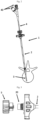
- an example of the embodiment of an assembly 1 is described allowing the positioning and blocking in position of an inflatable balloon 3 within a vertebral body.
- the assembly 1 comprises two sub-assemblies: a first sub-assembly comprising an access piece in the vertebral body, said piece being of elongated and cannulated shape, and a second sub-assembly formed by an inflatable balloon 3 mounted at the end of an advantageously flexible catheter 4.
- the balloon/rod (catheter) sub-assembly is arranged to slide through the access piece 2.
- the access piece is a rigid cannula.
- the catheter 4 comprises connection means 40 to a fluid delivery unit.
- the assembly 1 comprises means ensuring the stabilization of the balloon 3 relative to the vertebral body.
- the means for stabilizing the balloon 3 comprise first means ensuring the locking in position of the catheter, carrying at the end the balloon 3, on the access part 2 and second means ensuring the anchoring of the access part 2 in the vertebral body.
- the blocking means are in the form of a sleeve 5 mounted to slide along the catheter 4.
- the sleeve 5 and the access part 2 comprise means of reciprocal association.
- the sleeve 5 is screwed onto a hooking end piece 20 provided at the proximal end of the access part 2.
- the sleeve 5 comprises a longitudinal mounting slot 55 allowing the passage of the catheter 4 ( figure 9 ).
- the slot 55 is arranged to hold the sleeve 5 on the catheter while allowing it to slide along it.
- the sleeve 5 also comprises a retaining tip 50 for the catheter 4 when it is in place on the access part 2.
- the retaining tip 50 is a deformable tip of the clamp type. It has a side wall provided with a passage slot extending over its entire length. and communicating with the mounting slot 55.
- the retaining tip 50 is arranged to fit inside the hooking tip 20 of the access part 2.
- the retaining tip 50 has a truncated internal wall sized so that, when it is inserted into the hooking tip 20 of the access part 2, its section narrows in contact with the internal wall of the hooking tip 20 so as to enclose and block the movement of the catheter 4 of the balloon 3.
- the anchoring means consist, in the example illustrated, of a thread 6 provided on the peripheral wall of the cannulated part 2.
- the cannula 2 is configured to be traversed by a drilling instrument slidably mounted therein and comprising an axis provided with a tapered distal end allowing drilling of the vertebral body.
- the cannula and the drilling axis are sized relative to each other so that the tapered distal end of the drilling axis extends beyond the cannula.
- the cannula and the drilling instrument thus advantageously form a Jamshidi TM type instrument.
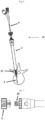
- THE figures 5 to 8 illustrate another exemplary embodiment of an assembly 10 allowing the positioning and locking in position of an inflatable balloon 3.
- the assembly 10 for positioning and locking in position of the balloon takes up all of the characteristics of the assembly previously described, and in particular the part locking the balloon 3 relative to the access part. It differs however by the constitution of the access part 2 and the anchoring means implemented.
- the access part 2 is formed not by a cannula as in the example previously described, but by an instrument coupled to an implant. More particularly, and as illustrated in the Figure 5 , the access part 2 comprises a tube 22 provided at the proximal end with a cannulated implant 21.
- the implant 21 is an anchoring pin.
- the anchoring peg 21, in the example illustrated, is in the form of a cannulated cylindrical peg body comprising two parts: an upper part 21a provided with an external helical thread 210 and an expandable lower part 21b.
- the peg 21 may be made of a thermoplastic material, preferably PEEK, or of metal.
- the upper part 210 provided with the thread allows primary anchoring of the peg in the vertebral body. It defines an area extending approximately over one third of the length of the peg 4.
- the lower part 21b has longitudinal slots delimiting arms that can expand radially. The longitudinal slots are advantageously non-opening at the proximal end of the ankle. The arms are thus connected to each other at the proximal end.
- the lower part 21b also includes external radial notches 211 arranged to block the movement of the ankle in a direction opposite to that of its insertion into the vertebral body, and thus preventing any untimely withdrawal of the ankle when it is anchored in the vertebral body.
- the ankle 21 constitutes the means of anchoring to the vertebral body.
Landscapes
- Health & Medical Sciences (AREA)
- Orthopedic Medicine & Surgery (AREA)
- Life Sciences & Earth Sciences (AREA)
- Surgery (AREA)
- Engineering & Computer Science (AREA)
- Biomedical Technology (AREA)
- Veterinary Medicine (AREA)
- Public Health (AREA)
- Heart & Thoracic Surgery (AREA)
- General Health & Medical Sciences (AREA)
- Animal Behavior & Ethology (AREA)
- Nuclear Medicine, Radiotherapy & Molecular Imaging (AREA)
- Molecular Biology (AREA)
- Medical Informatics (AREA)
- Oral & Maxillofacial Surgery (AREA)
- Neurology (AREA)
- Cardiology (AREA)
- Vascular Medicine (AREA)
- Transplantation (AREA)
- Chemical & Material Sciences (AREA)
- Dispersion Chemistry (AREA)
- Dentistry (AREA)
- Prostheses (AREA)
- Surgical Instruments (AREA)
- Media Introduction/Drainage Providing Device (AREA)
Description
- La présente invention concerne le domaine de la stabilisation des vertèbres, et plus particulièrement la restauration en hauteur (réduction) d'une vertèbre présentant un affaissement.
- L'invention concerne plus particulièrement un ensemble de positionnement et de blocage en position d'un ballonnet gonflable au sein d'un corps vertébral, lequel ensemble comprend une pièce d'accès canulée allongée à une zone au sein du corps vertébral, un ballonnet gonflable monté en extrémité d'un cathéter apte à être raccordé à une unité de délivrance d'un fluide, l'ensemble ballonnet et cathéter étant arrangé pour traverser de manière coulissante la pièce d'accès.
- Par cathéter, on entend dans la présente demande un tube mince et flexible permettant l'injection et/ou l'évacuation d'un liquide.
- Parmi les techniques de réduction d'une vertèbre affaissée, on connait la kyphoplastie. Cette technique consiste à réaliser la restauration de la hauteur vertébrale à l'aide d'un ballonnet, ou de tout autre dispositif apte à être expansé au sein du corps vertébral, placé dans le corps vertébral avant l'injection de ciment. Le ballonnet, et plus généralement le dispositif, est inséré par voie percutanée à travers le pédicule. A l'aide d'un cathéter, d'une seringue ou similaire, à l'extrémité duquel il est monté, le ballonnet est guidé au travers d'une canule de travail jusqu'au corps vertébral pour être ensuite gonflé de manière à réduire la fracture. Après réduction de la fracture, le ballonnet est dégonflé puis retiré. La cavité résultante reçoit alors un dépôt de ciment osseux pour stabiliser la fracture.
WO99/02214 A1 -
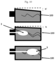
EP 3 081 178 A1 décrit un système d'implantation d'un produit de comblement osseux, comprenant un ballonet attaché a un cathéter. - L'une des problématiques rencontrées avec cette technique est le positionnement du ballonnet au sein de la vertèbre à restaurer. Un positionnement trop ou au contraire insuffisamment avancé au sein de la vertèbre a une influence sur le redressement de la vertèbre comme le montre la
figure 10 . Ainsi, et comme illustré sur la figure 10b, un ballonnet 3 insuffisamment avancé au sein de la vertèbre 100 ne permet pas de restaurer totalement la hauteur de la vertèbre : on peut voir en effet un décalage entre la hauteur de la vertèbre redressée et la hauteur optimale de redressement. Au contraire, comme illustré sur la figure 10c, le positionnement d'un ballonnet 3 plus loin dans le corps vertébral permet un redressement optimal de la vertèbre 100. - Une autre problématique rencontrée avec cette technique réside dans le maintien du ballonnet au sein de la vertèbre à redresser. En effet, sous l'action des efforts exercés sur le ballonnet par la vertèbre lors de son redressement, le ballonnet a tendance à glisser vers la zone dans laquelle s'exerce le moins de contraintes, de sorte que l'effet du ballonnet sur la restauration en hauteur de la vertèbre peut être amoindri. Le redressement en hauteur de la vertèbre sera d'autant moins important que le ballonnet sera peu avancé dans le corps vertébral.
- L'invention vise à remédier à ces problèmes en proposant un ensemble offrant un positionnement stabilisé du ballonnet gonflable au sein du corps vertébral pour ainsi assurer un redressement optimal de la vertèbre affaissée et ce, quel que soit le degré d'affaissement de cette dernière.
- A cet effet, et selon un premier aspect, l'invention propose un ensemble de positionnement et de blocage en position d'un ballonnet gonflable au sein d'un corps vertébral, comprenant une pièce d'accès au corps vertébral, canulée et de forme allongée, un ballonnet gonflable monté en extrémité d'un cathéter apte à être raccordé à une unité de délivrance d'un fluide, l'ensemble ballonnet et tige étant arrangé pour traverser de manière coulissante la pièce d'accès, l'ensemble étant remarquable en ce que la pièce d'accès comporte des moyens d'ancrage dans le corps vertébral et en ce qu'il comporte en outre des moyens de blocage en position du cathéter pourvu du ballonnet sur la pièce d'accès.
- La pièce d'accès, du fait de ses moyens d'ancrage dans le corps vertébral, forme, une fois ancrée dans la vertèbre, un canal de travail stabilisé par rapport à la vertèbre tandis que les moyens de blocage permettent de bloquer tout mouvement de coulissement du cathéter au travers de la pièce d'accès. La présence des moyens de blocage combiné avec l'ancrage de la pièce d'accès permet ainsi à la pièce d'accès ancrée d'établir un point fixe par rapport à la vertèbre mais aussi par rapport au cathéter. Cela facilite ainsi la mise en place du ballonnet et assure le maintien en position du celui-ci au sein de la vertèbre. Le positionnement du ballonnet n'est donc plus aléatoire comme cela est le cas avec les systèmes actuels de kyphoplastie, tout glissement du ballonnet lors de son gonflement étant évité.
- Avantageusement, les moyens d'ancrage consistent en au moins un filet.
- Avantageusement, la pièce d'accès est un implant.
- Selon une variante de réalisation, la pièce d'accès comprend un instrument prolongé de l'implant.
- Avantageusement, l'implant est une cheville d'ancrage.
- Selon une autre variante, la pièce d'accès est une canule. Avantageusement, la canule est configurée pour être traversée par un instrument de forage monté coulissant, ledit instrument de forage comportant un axe pourvu d'une extrémité distale effilée de sorte à permettre le forage du corps vertébral, la canule et l'axe de forage étant dimensionnés l'un par rapport à l'autre pour que l'extrémité distale effilée de la tige de forage s'étende au-delà de la canule.
- Avantageusement, les moyens de blocage sont arrangés pour autoriser un réglage du positionnement du cathéter par rapport à la pièce d'accès et bloquer le cathéter dans la position choisie par rapport à ladite pièce.
- Avantageusement, les moyens de blocage comportent un manchon monté coulissant sur le cathéter et des moyens de solidarisation du manchon sur la pièce d'accès.
- Avantageusement, le manchon comporte une fente de montage longitudinale pour le passage du cathéter au travers dudit manchon, ladite fente étant arrangée pour maintenir le manchon sur le cathéter tout en permettant son coulissement le long de ce dernier.
- D'autres caractéristiques et avantages de l'invention ressortiront de la description détaillée de l'invention qui va suivre en référence aux figures annexées et dans lesquelles :
- La
figure 1 représente un ensemble de positionnement et de blocage en position d'un ballonnet gonflable au sein d'un corps vertébral selon un premier exemple de réalisation ; - La
figure 2 représente l'ensemble de lafigure 1 en position dans une vertèbre, le ballonnet représenté en position dans le corps vertébral ; - La
figure 3 représente une vue de détail de la partie proximale de l'ensemble de lafigure 1 assurant le blocage du ballonnet ; - La
figure 4 représente une vue de détail de la partie distale de l'ensemble de lafigure 1 assurant le blocage du ballonnet ; - La
figure 5 représente un ensemble de positionnement et de blocage en position d'un ballonnet gonflable au sein d'un corps vertébral selon un deuxième exemple de réalisation ; - La
figure 6 représente l'ensemble de lafigure 5 en position dans une vertèbre, le ballonnet représenté en position dans le corps vertébral ; - La
figure 7 représente une vue de détail de la partie proximale de l'ensemble de lafigure 5 assurant le blocage du ballonnet ; - La
figure 8 représente une vue de détail de la partie distale de l'ensemble de lafigure 5 assurant le blocage du ballonnet ; - La
figure 9 représente une vue de détail des moyens de blocage du ballonnet ; - La
figure 10 montre l'impact du positionnement du ballonnet au sein d'une vertèbre sur le redressement de cette dernière. - Pour plus de clarté, les éléments identiques ou similaires des différents modes de réalisation sont repérés par des signes de référence identiques sur l'ensemble des figures.
- En relation avec les
figures 1 à 4 , il est décrit un exemple de réalisation d'un ensemble 1 permettant le positionnement et le blocage en position d'un ballonnet 3 gonflable au sein d'un corps vertébral. - L'ensemble 1 comprend deux sous-ensembles : un premier sous-ensemble comprenant une pièce d'accès dans le corps vertébral, ladite pièce-étant de forme allongée et canulée, et un deuxième sous-ensemble formé d'un ballonnet 3 gonflable monté en extrémité d'un cathéter 4 avantageusement flexible. Le sous ensemble ballonnet / tige (cathéter) est arrangé pour coulisser au travers de la pièce d'accès 2. Dans l'exemple illustré, la pièce d'accès est une canule rigide. Avantageusement, le cathéter 4 comporte des moyens de raccordement 40 à une unité de délivrance d'un fluide.
- Selon l'invention, l'ensemble 1 comporte des moyens assurant la stabilisation du ballonnet 3 par rapport au corps vertébral. Les moyens de stabilisation du ballonnet 3 comportent des premiers moyens assurant le blocage en position du cathéter, portant en extrémité le ballonnet 3, sur la pièce d'accès 2 et des deuxièmes moyens assurant l'ancrage de la pièce d'accès 2 dans le corps vertébral.
- Avantageusement, les moyens de blocage se présentent sous la forme d'un manchon 5 monté coulissant de long du cathéter 4.
- Selon un exemple de réalisation particulier illustré sur la
figure 3 , le manchon 5 et la pièce d'accès 2 comportent des moyens d'association réciproque. Dans le mode de réalisation illustré sur lafigure 3 , le manchon 5 est vissé sur un embout d'accroche 20 ménagé en extrémité proximale de la pièce d'accès 2. - Dans le mode de réalisation décrit, le manchon 5 comporte une fente de montage 55 longitudinale permettant le passage du cathéter 4 (
figure 9 ). La fente 55 est arrangée pour maintenir le manchon 5 sur le cathéter tout en autorisant son coulissement le long de celui-ci. - Le manchon 5 comporte également un embout de retenue 50 du cathéter 4 lorsqu'il est en place sur la pièce d'accès 2. L'embout de retenue 50 est un embout déformable de type pince. Il présente une paroi latérale pourvue d'une fente de passage s'étendant sur tout sa longueur et communiquant avec la fente de montage 55. L'embout de retenue 50 est arrangé pour s'insérer à l'intérieur de l'embout d'accroche 20 de la pièce d'accès 2. L'embout de retenue 50 présente une paroi interne tronconique dimensionnée pour que, lors de son insertion dans l'embout d'accroche 20 de la pièce d'accès 2, sa section se rétrécisse au contact de la paroi interne de l'embout d'accroche 20 de sorte à enserrer et bloquer le mouvement du cathéter 4 du ballonnet 3.
- Les moyens d'ancrage consistent, dans l'exemple illustré, à un filet 6 prévu sur la paroi périphérique de la pièce canulée 2.
- Avantageusement, la canule 2 est configurée pour être traversée par un instrument de forage monté coulissant dans celle-ci et comportant un axe pourvu d'une extrémité distale effilée permettant le forage du corps vertébral. La canule et l'axe de forage sont dimensionnés l'un par rapport à l'autre pour que l'extrémité distale effilée de l'axe de forage s'étende au-delà de la canule. La canule et l'instrument de forage forment ainsi avantageusement un instrument de type Jamshidi™.
- Les
figures 5 à 8 illustrent un autre exemple de réalisation d'un ensemble 10 permettant le positionnement et le blocage en position d'un ballonnet 3 gonflable. Dans ce mode de réalisation, l'ensemble 10 de positionnement et de blocage en position du ballonnet reprend l'ensemble des caractéristiques de l'ensemble précédemment décrit, et notamment la partie blocage du ballonnet 3 par rapport à la pièce d'accès. Il diffère cependant par la constitution de la pièce d'accès 2 et les moyens d'ancrage mis en œuvre. Selon cet exemple de réalisation, la pièce d'accès 2 est formée non pas par une canule comme dans l'exemple précédemment décrit, mais par un instrument couplé à un implant. Plus particulièrement, et comme illustré sur lafigure 5 , la pièce d'accès 2 comprend un tube 22 pourvu en extrémité proximale d'un implant canulé 21. Dans l'exemple illustré, l'implant 21 est une cheville d'ancrage. - La cheville d'ancrage 21, dans l'exemple illustré, se présente sous la forme d'un corps de cheville cylindrique canulé comprenant deux parties : une partie supérieure 21a pourvue d'un filetage 210 hélicoïdal externe et une partie inférieure 21b expansible. La cheville 21 peut être réalisée en un matériau thermoplastique, de préférence en PEEK, ou en métal. La partie supérieure 210 pourvue du filetage permet un ancrage primaire de la cheville dans le corps vertébral. Elle définit une zone s'étendant approximativement sur un tiers de la longueur de la cheville 4. La partie inférieure 21b comporte des fentes longitudinales délimitant des bras pouvant s'expanser radialement. Les fentes longitudinales sont avantageusement non débouchantes en extrémité proximale de la cheville. Les bras sont ainsi reliés entre eux en extrémité proximale. La partie inférieure 21b comporte également des crans radiaux 211 externes arrangés pour bloquer le mouvement de la cheville dans une direction opposée à celle de son insertion dans le corps vertébral, et empêchant ainsi tout retrait intempestif de la cheville lorsque celle-ci est ancrée dans le corps vertébral.
- Comme on le comprend, la cheville 21 constitue les moyens d'ancrage au corps vertébral.
- L'invention est décrite dans ce qui précède à titre d'exemple. Il est entendu que l'homme du métier est à même de réaliser différentes variantes de réalisation de l'invention sans pour autant sortir du cadre de l'invention.
Claims (10)
- Ensemble (1, 10) de positionnement et de blocage en position d'un ballonnet (3) gonflable au sein d'un corps vertébral, comprenant une pièce d'accès (2) au corps vertébral, canulée et de forme allongée, et un ballonnet (3) gonflable monté en extrémité d'un cathéter (4) apte à être raccordé à une unité de délivrance d'un fluide, l'ensemble ballonnet (3) et cathéter étant arrangé pour traverser de manière coulissante la pièce d'accès (2), la pièce d'accès (2) comporte des moyens d'ancrage dans le corps vertébral, caractérisé en ce que l'ensemble comprend en outre des moyens de blocage en position du cathéter pourvu du ballonnet (3) sur la pièce d'accès (2).
- Ensemble (1, 10) de positionnement et de blocage en position d'un ballonnet (3) gonflable selon la revendication 1, caractérisé en ce que les moyens d'ancrage consistent en au moins un filet (6).
- Ensemble (1, 10) de positionnement et de blocage en position d'un ballonnet (3) gonflable selon la revendication 1 ou la revendication 2, caractérisé en ce que la pièce d'accès (2) est un implant.
- Ensemble (1, 10) de positionnement et de blocage en position d'un ballonnet (3) gonflable selon la revendication 1 ou la revendication 2, caractérisé en ce que la pièce d'accès (2) comprend un instrument prolongé d'un implant.
- Ensemble (1, 10) de positionnement et de blocage en position d'un ballonnet (3) gonflable selon la revendication 3 ou la revendication 4, caractérisé en ce que l'implant est une cheville d'ancrage (21).
- Ensemble (1, 10) de positionnement et de blocage en position d'un ballonnet (3) gonflable selon la revendication 1 ou la revendication 2, caractérisé en ce que la pièce d'accès (2) est une canule.
- Ensemble (1, 10) de positionnement et de blocage en position d'un ballonnet (3) gonflable selon la revendication 6, caractérisé en ce que la canule est configurée pour être traversée par un instrument de forage monté coulissant, ledit instrument de forage comportant un axe pourvu d'une extrémité distale effilée de sorte à permettre le forage du corps vertébral, la canule et l'axe de forage étant dimensionnés l'un par rapport à l'autre pour que l'extrémité distale effilée de l'axe de forage s'étende au-delà de la canule.
- Ensemble (1, 10) de positionnement et de blocage en position d'un ballonnet (3) gonflable selon l'un quelconque des revendications précédentes, caractérisé en ce que les moyens de blocage sont arrangés pour autoriser un réglage du positionnement du cathéter par rapport à la pièce d'accès (2) et bloquer le cathéter dans la position choisie par rapport à ladite pièce.
- Ensemble (1, 10) de positionnement et de blocage en position d'un ballonnet (3) gonflable selon l'une quelconque des revendications précédentes, caractérisé en ce que les moyens de blocage comportent un manchon (5) monté coulissant sur le cathéter (4) et des moyens de solidarisation du manchon sur la pièce d'accès (2).
- Ensemble (1, 10) de positionnement et de blocage en position d'un ballonnet (3) gonflable selon la revendication 9, caractérisé en ce que le manchon (5) comporte une fente de montage (55) longitudinale pour le passage du cathéter au travers dudit manchon, ladite fente de montage (55) étant arrangée pour maintenir le manchon (5) sur le cathéter tout en permettant son coulissement le long de ce dernier.
Applications Claiming Priority (2)
| Application Number | Priority Date | Filing Date | Title |
|---|---|---|---|
| FR1903788A FR3094888B1 (fr) | 2019-04-09 | 2019-04-09 | Ensemble de positionnement et de blocage en position d’un ballonnet gonflable au sein d’un corps vertébral |
| PCT/EP2020/060145 WO2020208135A1 (fr) | 2019-04-09 | 2020-04-09 | Ensemble de positionnement et de blocage en position d'un ballonnet gonflable au sein d'un corps vertebral |
Publications (3)
| Publication Number | Publication Date |
|---|---|
| EP3952770A1 EP3952770A1 (fr) | 2022-02-16 |
| EP3952770B1 true EP3952770B1 (fr) | 2025-06-04 |
| EP3952770C0 EP3952770C0 (fr) | 2025-06-04 |
Family
ID=67999771
Family Applications (1)
| Application Number | Title | Priority Date | Filing Date |
|---|---|---|---|
| EP20717195.0A Active EP3952770B1 (fr) | 2019-04-09 | 2020-04-09 | Ensemble de positionnement et de blocage en position d'un ballonnet gonflable au sein d'un corps vertebral |
Country Status (5)
| Country | Link |
|---|---|
| US (1) | US20220202461A1 (fr) |
| EP (1) | EP3952770B1 (fr) |
| JP (1) | JP2022527718A (fr) |
| FR (1) | FR3094888B1 (fr) |
| WO (1) | WO2020208135A1 (fr) |
Family Cites Families (12)
| Publication number | Priority date | Publication date | Assignee | Title |
|---|---|---|---|---|
| US6852095B1 (en) * | 1997-07-09 | 2005-02-08 | Charles D. Ray | Interbody device and method for treatment of osteoporotic vertebral collapse |
| CA2328229C (fr) * | 1997-07-09 | 2007-04-17 | Tegementa, L.L.C. | Dispositif intermediaire et procede utiles pour traiter un tassement vertebral osteoporotique |
| US20120316648A1 (en) * | 1999-08-18 | 2012-12-13 | Intrinsic Therapeutics, Inc. | Intervertebral disc reinforcement systems |
| KR20030029621A (ko) * | 2000-07-14 | 2003-04-14 | 카이폰 인코포레이티드 | 척추체의 치료 시스템 및 방법 |
| US7544196B2 (en) * | 2001-02-20 | 2009-06-09 | Orthovita, Inc. | System and kit for delivery of restorative materials |
| US20090171461A1 (en) * | 2005-08-26 | 2009-07-02 | Magellan Spine Technologies, Inc. | Spinal implants and methods |
| US20090299378A1 (en) * | 2008-06-02 | 2009-12-03 | Knopp Peter G | Controlled deployment handles for bone stabilization devices |
| US8617053B2 (en) * | 2009-04-24 | 2013-12-31 | Warsaw Othropedic, Inc. | Remote position control for surgical apparatus |
| US9326799B2 (en) * | 2009-12-07 | 2016-05-03 | Globus Medical, Inc. | Methods and apparatus for treating vertebral fractures |
| TWI495458B (zh) * | 2012-11-13 | 2015-08-11 | Univ Chang Gung | A device that supports bone strength |
| US9730746B2 (en) * | 2013-03-15 | 2017-08-15 | Kyphon SÀRL | Device for performing a surgical procedure and method |
| CN103637842B (zh) * | 2013-12-12 | 2017-05-10 | 宁波华科润生物科技有限公司 | 一种骨填充物植入系统 |
-
2019
- 2019-04-09 FR FR1903788A patent/FR3094888B1/fr not_active Expired - Fee Related
-
2020
- 2020-04-09 EP EP20717195.0A patent/EP3952770B1/fr active Active
- 2020-04-09 US US17/601,810 patent/US20220202461A1/en not_active Abandoned
- 2020-04-09 WO PCT/EP2020/060145 patent/WO2020208135A1/fr not_active Ceased
- 2020-04-09 JP JP2021560618A patent/JP2022527718A/ja active Pending
Also Published As
| Publication number | Publication date |
|---|---|
| FR3094888B1 (fr) | 2022-10-07 |
| FR3094888A1 (fr) | 2020-10-16 |
| EP3952770C0 (fr) | 2025-06-04 |
| US20220202461A1 (en) | 2022-06-30 |
| WO2020208135A1 (fr) | 2020-10-15 |
| JP2022527718A (ja) | 2022-06-03 |
| EP3952770A1 (fr) | 2022-02-16 |
Similar Documents
| Publication | Publication Date | Title |
|---|---|---|
| EP2953564B1 (fr) | Ensemble d'implantation comprenant un instrument d'entraînement pre-monté sur un implant osseux | |
| EP1073373B1 (fr) | Implant osseux comprenant un dispositif de fixation reversible | |
| EP1532930A1 (fr) | Ancre de suture à expansion réversible | |
| EP3119298B1 (fr) | Ensemble chirurgical, vis d'ancrage osseux et dispositif d'extension d'une telle vis faisant parties dudit ensemble chirurgical | |
| FR2910269A1 (fr) | Materiel de traitement d'une valve cardiaque,en particulier d'une valve mitrale | |
| FR2970864A1 (fr) | Systeme de delivrance d'un stent | |
| EP2874552B1 (fr) | Dispositif de guidage d'un instrument chirurgical en position sur un element d'ancrage osseux comprenant des moyens de realignement d'une tige de liaison avec l'element d'ancrage et systeme d'instrumentation chirurgical associe | |
| FR2736257A1 (fr) | Piece d'ancrage pour tissu vivant et son appareil de conditionnement et de mise en place | |
| EP2854674B1 (fr) | Systeme d'instrumentation pour la realisation d'une intervention chirurgicale sur des vertebres comprenant des moyens de blocage temporaire | |
| EP2140824A1 (fr) | Ancrage canulé d'os avec élément de prise et outil d'insertion de l'élément de prise dans l'ancrage d'os | |
| EP4132391B1 (fr) | Implant d'ancrage osseux à stabilisation corticale | |
| CA2966590A1 (fr) | Dispositif de guidage securise | |
| WO2020208135A1 (fr) | Ensemble de positionnement et de blocage en position d'un ballonnet gonflable au sein d'un corps vertebral | |
| WO2018024617A1 (fr) | Implant deployable | |
| EP3490510A1 (fr) | Stent intra-osseux | |
| FR3004636A1 (fr) | Ensemble de reprise pour materiel d'osteosynthese vertebrale | |
| EP3116426A1 (fr) | Systeme d'osteosynthese comprenant des moyens de redressement d'un element d'ancrage osseux par rapport a une tete de vis et vis d'ancrage mise en oeuvre dans un tel systeme | |
| WO2020043629A1 (fr) | Dispositif d'aide a la reconstruction d'une vertebre | |
| EP3565491A1 (fr) | Vis osseuse pour dispositif d'ostéosynthèse, ensemble formé par une vis, un connecteur et un écrou, et kit comportant au moins un tel ensemble | |
| EP1967150A1 (fr) | Dispositif d'ancrage vertébral par clou intrapédiculaire | |
| WO2014191663A1 (fr) | Dispositif d'ostéosynthèse à vis cervico-céphalique | |
| EP4717207A1 (fr) | Instruments de chirurgie orthopédique humaine d'installation d'implants osseux expansibles | |
| WO2015132480A1 (fr) | Dispositif pour réaliser une dérivation sur un vaisseau sanguin | |
| EP4717211A1 (fr) | Implant osseux expansible de chirurgie orthopédique vétérinaire, système orthopédique et instrument associé | |
| WO2020245515A1 (fr) | Systeme de fixation entre un dispositif medical et au moins une partie d'un os |
Legal Events
| Date | Code | Title | Description |
|---|---|---|---|
| STAA | Information on the status of an ep patent application or granted ep patent |
Free format text: STATUS: UNKNOWN |
|
| STAA | Information on the status of an ep patent application or granted ep patent |
Free format text: STATUS: THE INTERNATIONAL PUBLICATION HAS BEEN MADE |
|
| PUAI | Public reference made under article 153(3) epc to a published international application that has entered the european phase |
Free format text: ORIGINAL CODE: 0009012 |
|
| STAA | Information on the status of an ep patent application or granted ep patent |
Free format text: STATUS: REQUEST FOR EXAMINATION WAS MADE |
|
| 17P | Request for examination filed |
Effective date: 20211019 |
|
| AK | Designated contracting states |
Kind code of ref document: A1 Designated state(s): AL AT BE BG CH CY CZ DE DK EE ES FI FR GB GR HR HU IE IS IT LI LT LU LV MC MK MT NL NO PL PT RO RS SE SI SK SM TR |
|
| DAV | Request for validation of the european patent (deleted) | ||
| DAX | Request for extension of the european patent (deleted) | ||
| GRAP | Despatch of communication of intention to grant a patent |
Free format text: ORIGINAL CODE: EPIDOSNIGR1 |
|
| STAA | Information on the status of an ep patent application or granted ep patent |
Free format text: STATUS: GRANT OF PATENT IS INTENDED |
|
| INTG | Intention to grant announced |
Effective date: 20241210 |
|
| GRAS | Grant fee paid |
Free format text: ORIGINAL CODE: EPIDOSNIGR3 |
|
| GRAA | (expected) grant |
Free format text: ORIGINAL CODE: 0009210 |
|
| STAA | Information on the status of an ep patent application or granted ep patent |
Free format text: STATUS: THE PATENT HAS BEEN GRANTED |
|
| AK | Designated contracting states |
Kind code of ref document: B1 Designated state(s): AL AT BE BG CH CY CZ DE DK EE ES FI FR GB GR HR HU IE IS IT LI LT LU LV MC MK MT NL NO PL PT RO RS SE SI SK SM TR |
|
| REG | Reference to a national code |
Ref country code: GB Ref legal event code: FG4D Free format text: NOT ENGLISH |
|
| REG | Reference to a national code |
Ref country code: CH Ref legal event code: EP |
|
| REG | Reference to a national code |
Ref country code: DE Ref legal event code: R096 Ref document number: 602020052258 Country of ref document: DE |
|
| REG | Reference to a national code |
Ref country code: IE Ref legal event code: FG4D Free format text: LANGUAGE OF EP DOCUMENT: FRENCH |
|
| U01 | Request for unitary effect filed |
Effective date: 20250703 |
|
| RAP4 | Party data changed (patent owner data changed or rights of a patent transferred) |
Owner name: SAFE ORTHOPAEDICS |
|
| U07 | Unitary effect registered |
Designated state(s): AT BE BG DE DK EE FI FR IT LT LU LV MT NL PT RO SE SI Effective date: 20250710 |
|
| PG25 | Lapsed in a contracting state [announced via postgrant information from national office to epo] |
Ref country code: ES Free format text: LAPSE BECAUSE OF FAILURE TO SUBMIT A TRANSLATION OF THE DESCRIPTION OR TO PAY THE FEE WITHIN THE PRESCRIBED TIME-LIMIT Effective date: 20250604 |
|
| PG25 | Lapsed in a contracting state [announced via postgrant information from national office to epo] |
Ref country code: GR Free format text: LAPSE BECAUSE OF FAILURE TO SUBMIT A TRANSLATION OF THE DESCRIPTION OR TO PAY THE FEE WITHIN THE PRESCRIBED TIME-LIMIT Effective date: 20250905 Ref country code: NO Free format text: LAPSE BECAUSE OF FAILURE TO SUBMIT A TRANSLATION OF THE DESCRIPTION OR TO PAY THE FEE WITHIN THE PRESCRIBED TIME-LIMIT Effective date: 20250904 |
|
| PG25 | Lapsed in a contracting state [announced via postgrant information from national office to epo] |
Ref country code: PL Free format text: LAPSE BECAUSE OF FAILURE TO SUBMIT A TRANSLATION OF THE DESCRIPTION OR TO PAY THE FEE WITHIN THE PRESCRIBED TIME-LIMIT Effective date: 20250604 |
|
| PG25 | Lapsed in a contracting state [announced via postgrant information from national office to epo] |
Ref country code: HR Free format text: LAPSE BECAUSE OF FAILURE TO SUBMIT A TRANSLATION OF THE DESCRIPTION OR TO PAY THE FEE WITHIN THE PRESCRIBED TIME-LIMIT Effective date: 20250604 |
|
| PG25 | Lapsed in a contracting state [announced via postgrant information from national office to epo] |
Ref country code: RS Free format text: LAPSE BECAUSE OF FAILURE TO SUBMIT A TRANSLATION OF THE DESCRIPTION OR TO PAY THE FEE WITHIN THE PRESCRIBED TIME-LIMIT Effective date: 20250904 |
|
| PG25 | Lapsed in a contracting state [announced via postgrant information from national office to epo] |
Ref country code: IS Free format text: LAPSE BECAUSE OF FAILURE TO SUBMIT A TRANSLATION OF THE DESCRIPTION OR TO PAY THE FEE WITHIN THE PRESCRIBED TIME-LIMIT Effective date: 20251004 |
|
| PG25 | Lapsed in a contracting state [announced via postgrant information from national office to epo] |
Ref country code: SM Free format text: LAPSE BECAUSE OF FAILURE TO SUBMIT A TRANSLATION OF THE DESCRIPTION OR TO PAY THE FEE WITHIN THE PRESCRIBED TIME-LIMIT Effective date: 20250604 |
|
| PG25 | Lapsed in a contracting state [announced via postgrant information from national office to epo] |
Ref country code: CZ Free format text: LAPSE BECAUSE OF FAILURE TO SUBMIT A TRANSLATION OF THE DESCRIPTION OR TO PAY THE FEE WITHIN THE PRESCRIBED TIME-LIMIT Effective date: 20250604 |
|
| PG25 | Lapsed in a contracting state [announced via postgrant information from national office to epo] |
Ref country code: SK Free format text: LAPSE BECAUSE OF FAILURE TO SUBMIT A TRANSLATION OF THE DESCRIPTION OR TO PAY THE FEE WITHIN THE PRESCRIBED TIME-LIMIT Effective date: 20250604 |
|
| PLBE | No opposition filed within time limit |
Free format text: ORIGINAL CODE: 0009261 |
|
| STAA | Information on the status of an ep patent application or granted ep patent |
Free format text: STATUS: NO OPPOSITION FILED WITHIN TIME LIMIT |
|
| REG | Reference to a national code |
Ref country code: CH Ref legal event code: L10 Free format text: ST27 STATUS EVENT CODE: U-0-0-L10-L00 (AS PROVIDED BY THE NATIONAL OFFICE) Effective date: 20260416 |
|
| 26N | No opposition filed |
Effective date: 20260305 |
|
| U20 | Renewal fee for the european patent with unitary effect paid |
Year of fee payment: 7 Effective date: 20260422 |