EP3952062A1 - Stator and motor comprising said stator - Google Patents
Stator and motor comprising said stator Download PDFInfo
- Publication number
- EP3952062A1 EP3952062A1 EP20779349.8A EP20779349A EP3952062A1 EP 3952062 A1 EP3952062 A1 EP 3952062A1 EP 20779349 A EP20779349 A EP 20779349A EP 3952062 A1 EP3952062 A1 EP 3952062A1
- Authority
- EP
- European Patent Office
- Prior art keywords
- stator
- claw magnetic
- magnetic pole
- rotor
- contact
- Prior art date
- Legal status (The legal status is an assumption and is not a legal conclusion. Google has not performed a legal analysis and makes no representation as to the accuracy of the status listed.)
- Pending
Links
Images





Classifications
-
- H—ELECTRICITY
- H02—GENERATION; CONVERSION OR DISTRIBUTION OF ELECTRIC POWER
- H02K—DYNAMO-ELECTRIC MACHINES
- H02K1/00—Details of the magnetic circuit
- H02K1/06—Details of the magnetic circuit characterised by the shape, form or construction
- H02K1/12—Stationary parts of the magnetic circuit
- H02K1/14—Stator cores with salient poles
- H02K1/145—Stator cores with salient poles having an annular coil, e.g. of the claw-pole type
-
- H—ELECTRICITY
- H02—GENERATION; CONVERSION OR DISTRIBUTION OF ELECTRIC POWER
- H02K—DYNAMO-ELECTRIC MACHINES
- H02K1/00—Details of the magnetic circuit
- H02K1/04—Details of the magnetic circuit characterised by the material used for insulating the magnetic circuit or parts thereof
-
- H—ELECTRICITY
- H02—GENERATION; CONVERSION OR DISTRIBUTION OF ELECTRIC POWER
- H02K—DYNAMO-ELECTRIC MACHINES
- H02K1/00—Details of the magnetic circuit
- H02K1/06—Details of the magnetic circuit characterised by the shape, form or construction
- H02K1/12—Stationary parts of the magnetic circuit
- H02K1/18—Means for mounting or fastening magnetic stationary parts on to, or to, the stator structures
- H02K1/187—Means for mounting or fastening magnetic stationary parts on to, or to, the stator structures to inner stators
-
- H—ELECTRICITY
- H02—GENERATION; CONVERSION OR DISTRIBUTION OF ELECTRIC POWER
- H02K—DYNAMO-ELECTRIC MACHINES
- H02K2213/00—Specific aspects, not otherwise provided for and not covered by codes H02K2201/00 - H02K2211/00
- H02K2213/03—Machines characterised by numerical values, ranges, mathematical expressions or similar information
Definitions
- the present disclosure relates to a stator and a motor including the stator.
- Patent Document 1 discloses a motor including a three-phase claw pole stator.
- the stator iron cores of the respective phases of the stator in the circumferential direction of the rotor are stacked such that the positions of the stator iron cores of the phases of electrical angles are different from each other by 120°.
- a circular coupling plate made of a non-magnetic plastic material is arranged between the stator iron cores of the phases. The stator iron core of each phase is positioned by the coupling plate.
- Patent Document 1 Japanese Laid-Open Patent Publication No. 2008-148397
- one side surface of the coupling plate includes a projection
- one side surface of each stator iron core includes a recess.
- the stator iron core is positioned relative to the coupling plate by engaging the projection with the recess.
- the projections of the coupling plate are arranged on the opposite sides of the coupling plate.
- a stator that solves the problem includes: stator iron cores stacked in an axial direction of a rotor; and an interphase insulating member arranged between the stator iron cores.
- the stator iron cores each include a circular back yoke and a stator claw magnetic pole that protrudes from the back yoke in a radial direction of the rotor.
- the interphase insulating member includes an insulating portion, arranged between adjacent ones of the stator iron cores, and a support. The stator claw magnetic pole is in contact with the support in at least one of a circumferential direction of the rotor and the radial direction of the rotor.
- each stator iron core is positioned through the contact between the stator claw magnetic pole and the support in at least one of the circumferential direction of the rotor and the radial direction of the rotor. This allows the stator iron cores to be positioned relative to each other without complicating the structures of the stator iron cores.
- the support include a first support extending in the axial direction of the rotor from a first surface of the insulating portion in the axial direction of the rotor and a second support extending in the axial direction of the rotor from a second surface on a side opposite from the first surface of the insulating portion and that the first support be located at a position that differs from a position of the second support in the circumferential direction of the rotor.
- one of the stator iron cores adjacent to the interphase insulating member is positioned through the contact between the stator claw magnetic pole and the first support, and the other one of the stator iron cores adjacent to the interphase insulating member is positioned through the contact between the stator claw magnetic pole and the second support.
- stator iron cores each include a first stator and a second stator, that the first stator include a circular first back yoke and a first stator claw magnetic pole that protrudes from the first back yoke in the radial direction of the rotor and that the second stator include a circular second back yoke and a second stator claw magnetic pole that protrudes from the second back yoke in the radial direction of the rotor.
- This structure simplifies the structures of the stator iron cores.
- the first stator claw magnetic pole protrude from the first back yoke in the radial direction of the rotor and extends at least toward the second stator in the axial direction of the rotor and that the second stator claw magnetic pole protrude from the second back yoke in the radial direction of the rotor, and extend at least toward the first stator in the axial direction of the rotor such that a void is created between the first stator claw magnetic pole and the second stator claw magnetic pole in the circumferential direction of the rotor.
- the stator iron core is configured such that the first stator claw magnetic pole and the second stator claw magnetic pole are laid out in the circumferential direction of the rotor.
- This structure increases the areas of the stator iron cores opposing the rotor and thus contributes to generating torque in a stable manner.
- the insulating portion be in contact with, in the axial direction of the rotor, a tip of one of the stator claw magnetic poles extending toward the insulating portion in the first stator claw magnetic pole and the second stator claw magnetic pole of the stator iron core adjacent to the insulating portion.
- the tip of one of the first and second stator claw magnetic poles is supported by the insulating portion in the axial direction of the rotor so as to reinforce the stator claw magnetic pole. This improves the strength of the stator iron core.
- the support be in contact with, in the circumferential direction of the rotor, the first stator claw magnetic pole and the second stator claw magnetic pole of the stator iron core adjacent to the insulating portion.
- the first stator in the stator iron core adjacent to the insulating portion, is positioned in the circumferential direction of the rotor through the contact between the first stator claw magnetic pole and the support and the second stator is positioned in the circumferential direction of the rotor through the contact between the second stator claw magnetic pole and the support. This allows the first stator and the second stator to be positioned relative to each other in the circumferential direction of the rotor.
- the support be in contact with, in the circumferential direction of the rotor, one of the first stator claw magnetic pole and the second stator claw magnetic pole of the stator iron core adjacent to the insulating portion and be in contact with, in the radial direction of the rotor, the other one of the first stator claw magnetic pole and the second stator claw magnetic pole.
- the first stator is positioned in one of the circumferential direction of the rotor and the radial direction of the rotor through the contact between the first stator claw magnetic pole and the support and the second stator is positioned in the other one of the circumferential direction of the rotor and the radial direction of the rotor through the contact between the second stator claw magnetic pole and the support.
- This allows the first stator and the second stator to be positioned relative to each other in the circumferential direction of the rotor and the radial direction of the rotor.
- stator iron cores be each formed using a powder magnetic core.
- This structure prevents the generation of eddy currents and thus contributes to reducing eddy-current losses. Additionally, the degree of freedom in the shape of the stator iron core improves.
- a motor that solves the above-described problem includes the stator and the rotor.
- each stator iron core is positioned through the contact between the stator claw magnetic pole and the support in at least one of the circumferential direction of the rotor and the radial direction of the rotor. This allows the stator iron cores to be positioned relative to each other without complicating the structures of the stator iron cores.
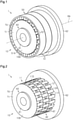
- a motor 1 according to a first embodiment will now be described.
- the scope of the present disclosure is defined not by the detailed description but by the claims and their equivalents, and all variations within the scope of the claims and their equivalents are to be construed as being included in the disclosure.
- the motor 1 is of an outer-rotor type.
- the motor 1 is installed in, for example, an air conditioner (not shown).
- the motor 1 is capable of driving a sirocco fan (not shown) installed in the air conditioner.
- the motor 1 includes a claw-pole stator 10 (hereinafter referred to as the stator 10), a rotor 50 capable of rotating relative to the stator 10, and a fixing member 60 capable of fixing the stator 10.
- the rotor 50 includes a rotation axis RA.
- the rotor 50 is capable of rotating about the rotation axis RA.
- the rotor 50 includes rotor iron cores 51 stacked in the axial direction of the rotation axis RA and magnets 52 arranged on an inner circumferential surface 51A of each rotor iron core 51.
- the axial direction of the rotation axis RA coincides with the axial direction of the rotor 50 (hereinafter referred to as the axial direction).
- Each rotor iron core 51 is, for example, annular.
- the number of the rotor iron cores 51 coincides with the number of stator iron cores 11 (refer to Fig. 2 ) included in the stator 10.
- the number of the rotor iron cores 51 is three.
- the magnets 52 are, for example, laid out on the inner circumferential surface 51A of each rotor iron core 51 in the circumferential direction so as to oppose an outer circumferential surface 11D (refer to Fig. 2 ) of the corresponding stator iron core 11.
- twenty magnets 52 are laid out in the circumferential direction of the rotation axis RA on the inner circumferential surface 51A of each rotor iron core 51.
- the circumferential direction of the rotation axis RA coincides with the circumferential direction of the rotor 50 (hereinafter referred to as the circumferential direction).
- the magnets 52 are, for example, permanent magnets.
- the stator 10 includes the stator iron cores 11 stacked in the axial direction and interphase insulating members 40 each arranged between the corresponding stator iron cores 11.
- the stator iron cores 11 are each formed using a powder magnetic core.
- the number of the stator iron cores 11 is two or more.
- the number of the stator iron cores 11 is three.
- the stator 10 of the present embodiment is a three-phase claw-pole stator with a three-dimensional magnetic structure in which the stator iron cores 11 are stacked in the order of U-phase, V-phase, and W-phase.
- the stator iron cores 11 of the respective phases in the circumferential direction are stacked such that the positions of the stator iron cores 11 of the phases of electrical angles are different from each other by 120°.
- Each interphase insulating member 40 is non-magnetic.
- the interphase insulating member 40 is made of, for example, plastic.
- Each interphase insulating member 40 is arranged between ones of the stator iron cores 11 adjacent to each other in the axial direction such that one of the stator iron cores 11 is insulated from the other one of the stator iron cores 11.
- the number of the interphase insulating members 40 is determined by the number of the stator iron cores 11. For example, the number of the interphase insulating members 40 is two.
- the dotted parts in Fig. 2 illustrate the interphase insulating members 40.
- the stator 10 further includes an insulating member 70 arranged between the stator iron cores 11 and the fixing member 60.
- the insulating member 70 is non-magnetic.
- the insulating member 70 is made of, for example, plastic.
- the insulating member 70 is arranged between the stator iron cores 11 and the fixing member 60 such that the stator iron cores 11 and the fixing member 60 are insulated from each other.
- the insulating member 70 is arranged in at least one of a section between the stator iron cores 11 and a first end plate 61 of the fixing member 60 and a section between the stator iron cores 11 and a second end plate 62 of the fixing member 60 in the axial direction.
- the insulating member 70 is arranged between the stator iron cores 11 and the first end plate 61 of the fixing member 60.
- the insulating member 70 has the shape of one of the two pieces into which each interphase insulating member 40 is split along a plane that is orthogonal to the axial direction.
- the insulating member 70 includes a flat end surface 71 opposing the first end plate 61 of the fixing member 60.
- the end surface 71 of the insulating member 70 defines one end surface 10B of the stator 10.
- the insulating member 70 may have the substantially same shape as the interphase insulating member 40 and may have the shape of a flat plate.
- the shape of one of the two pieces into which the interphase insulating member 40 is split along the plane that is orthogonal to the axial direction may be formed on a portion of the second end plate 62 opposing the stator iron cores 11.
- the stator 10 does not have to include the insulating member 70.
- the end surface 10B of the stator 10 is formed by an end surface 11B of the U-phase stator iron core 11 opposing the first end plate 61 of the fixing member 60.
- the stator 10 includes a through-hole 10A extending through in the axial direction.
- each stator iron core 11 includes a through-hole 11A extending through in the axial direction
- each interphase insulating member 40 includes a through-hole 40A extending through in the axial direction
- the insulating member 70 includes a through-hole 70A extending through in the axial direction.
- the through-hole 11A of each stator iron core 11, the through-hole 40A of each interphase insulating member 40, and the through-hole 70A of the insulating member 70 form the through-hole 10A of the stator 10.
- the through-hole 11A of each stator iron core 11, the through-hole 40A of each interphase insulating member 40, and the through-hole 70A of the insulating member 70 have the substantially same size.
- the fixing member 60 includes the first end plate 61, the second end plate 62, and one or more rod portions 63.
- the first end plate 61 has the shape of, for example, a circular plate.
- the first end plate 61 is arranged in contact with the end surface 10B in the axial direction.
- the first end plate 61 is arranged in contact with the end surface 71 of the insulating member 70.
- the first end plate 61 is arranged in contact with the end surface 11B of the U-phase stator iron core 11.
- the second end plate 62 has the shape of, for example, a circular plate.
- the second end plate 62 has the shape of a circular plate with a larger diameter than the first end plate 61.
- the second end plate 62 is arranged in contact with the other end surface 10C (refer to Fig. 8 ) in the axial direction in the stator 10.
- the other end surface 10C of the stator 10 is defined by an end surface 11C (refer to Fig. 8 ) of the W-phase stator iron core 11.
- the second end plate 62 is arranged in contact with the end surface 11C of the W-phase stator iron core 11.
- the rod portion 63 is insertable into the through-hole 10A of the stator 10.
- the rod portion 63 and the first and second end plates 61, 62 are fixed with the rod portion 63 inserted into the through-hole 10A of the stator 10 and the stator 10 held between the first end plate 61 and the second end plate 62 in the axial direction.
- One of the first end plate 61 and the second end plate 62 is formed integrally with the rod portion 63.
- the rod portion 63 of the present embodiment is formed integrally with the first end plate 61.
- the rod portion 63 may be formed integrally with the second end plate 62.
- the rod portion 63 includes a thread groove 63A.
- the thread groove 63A is formed on an outer circumferential surface 63B of the rod portion 63.
- the thread groove 63A is formed on a tip 63C of the rod portion 63.
- At least one of the first end plate 61 and the second end plate 62 includes a thread groove 62A that can be threaded to the thread groove 63A of the rod portion 63.
- the second end plate 62 includes an insertion hole 62B into which the rod portion 63 is insertable.
- the insertion hole 62B extends through, for example, in the axial direction.
- the insertion hole 62B does not have to extend through in the axial direction.
- the thread groove 62A is formed in the insertion hole 62B of the second end plate 62.
- the first end plate 61 and the second end plate 62 may both include the thread groove 62A.
- the rod portion 63 is fixed to the second end plate 62 by inserting the rod portion 63 into the insertion hole 62B of the second end plate 62 through the through-hole 10A of the stator 10 and fastening the thread groove 63A of the rod portion 63 to the thread groove 62A of the second end plate 62.
- the stator 10 is fixed so as to be held between the first end plate 61 and the second end plate 62 (refer to Fig. 8 ).
- each stator iron core 11 will now be described with reference to Fig. 4 .
- the stator iron core 11 includes a circular back yoke 12 and stator claw magnetic poles 13 that protrude from the back yoke 12 in the radial direction of the rotor 50 (hereinafter referred to as the radial direction).
- the back yoke 12 of the present embodiment is annular.
- the through-hole 11A of the stator iron core 11 is formed in the back yoke 12.
- the back yoke 12 includes the through-hole 11A.
- the stator claw magnetic poles 13 protrude in the radial direction from an outer circumferential surface 12A of the back yoke 12 and extends in the axial direction.
- the stator iron core 11 includes a first stator 20 and a second stator 30.
- the first stator 20 includes a circular first back yoke 21 and first stator claw magnetic poles 22 that protrude from the first back yoke 21 in the radial direction.
- the first back yoke 21 of the present embodiment is annular.
- the first back yoke 21 is included in the back yoke 12.
- the first stator claw magnetic poles 22 protrude from the first back yoke 21 in the radial direction and extend at least toward the second stator 30 in the axial direction. For example.
- the first stator claw magnetic poles 22 protrude from the outer circumferential surface 21A of the first back yoke 21 in the radial direction and extend toward the second stator 30 in the axial direction.
- the first stator claw magnetic poles 22 are included in the stator claw magnetic poles 13.
- the number of the first stator claw magnetic poles 22 is, for example, ten.
- the first stator claw magnetic poles 22 are arranged, for example, at equal intervals in the circumferential direction on the outer circumferential surface 21A of the first back yoke 21.
- Each first stator claw magnetic pole 22 includes a first claw magnetic pole 23 and a second claw magnetic pole 24.
- the first claw magnetic pole 23 is a portion including the root of the first stator claw magnetic pole 22.
- the first claw magnetic pole 23 extends in the radial direction from the outer circumferential surface 21A of the first back yoke 21.
- the second claw magnetic pole 24 is a portion including a tip 24A of the first stator claw magnetic pole 22.
- the second claw magnetic pole 24 extends from the first claw magnetic pole 23 toward the second stator 30.
- the second claw magnetic pole 24 has, for example, a parallelepiped shape.
- the second stator 30 has, for example, the substantially same structure as the first stator 20.
- the second stator 30 includes a circular second back yoke 31 and second stator claw magnetic poles 32 that protrude from the second back yoke 31 in the radial direction.
- the second back yoke 31 of the present embodiment is annular.
- the second back yoke 31 is included in the back yoke 12.
- Each second stator claw magnetic pole 32 protrudes from the second back yoke 31 in the radial direction, and extends at least toward the first stator 20 in the axial direction such that a void G (refer to Fig. 3 ) is created between the first stator claw magnetic pole 22 and the second stator claw magnetic pole 32 in the circumferential direction.
- the second stator claw magnetic poles 32 protrude from the outer circumferential surface 31A of the second back yoke 31 in the radial direction and extend toward the first stator 20 in the axial direction.
- the second stator claw magnetic poles 32 are included in the stator claw magnetic poles 13.
- the number of the second stator claw magnetic poles 32 is, for example, ten.
- the second stator claw magnetic poles 32 are arranged, for example, at equal intervals in the circumferential direction on the outer circumferential surface 31A of the second back yoke 31.
- Each second stator claw magnetic pole 32 includes a first claw magnetic pole 33 and a second claw magnetic pole 34.
- the first claw magnetic pole 33 is a portion including the root of the second stator claw magnetic pole 32.
- the first claw magnetic pole 33 extends in the radial direction from the outer circumferential surface 31A of the second back yoke 31.
- the second claw magnetic pole 34 is a portion including a tip 34A of the second stator claw magnetic pole 32.
- the second claw magnetic pole 34 extends from the first claw magnetic pole 33 toward the first stator 20 such that the void G is created between the second claw magnetic pole 34 and the second claw magnetic pole 24 of the first stator claw magnetic pole 22 in the circumferential direction.
- the second claw magnetic pole 34 has, for example, a parallelepiped shape.
- an outer surface 34B of each second claw magnetic pole 34 which is a part of the outer circumferential surface 11D of the stator iron core 11, opposes the corresponding magnet 52 of the rotor 50.
- the stator 10 further includes a coil 14 wound around in an annular manner.
- the coil 14 is connected to, for example, an inverter circuit or a current conversion circuit (not shown).
- the coil 14 is arranged between the first stator 20 and the second stator 30 in the axial direction.
- the coil 14 is arranged between the first stator 20 and the second stator 30 in the circumferential direction, and the stator iron core 11 is formed by coupling the first stator 20 to the second stator 30 so as to create the void G between each first stator claw magnetic pole 22 and the corresponding second stator claw magnetic pole 32.
- the positional relationship between the first stator 20 and the second stator 30 is determined by the interphase insulating member 40, and the first stator 20 is coupled to the second stator 30 by the fixing member 60.
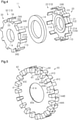
- each interphase insulating member 40 will now be described with reference to Figs. 5 to 7 .
- the interphase insulating member 40 includes an insulating portion 41, arranged between adjacent ones of the stator iron cores 11, and supports 42.
- the insulating portion 41 is, for example, annular.
- the insulating portion 41 has a sheet shape, a hollow shape, or a mesh shape.
- the insulating portion 41 of the present embodiment has a sheet shape.
- the supports 42 are arranged on the insulating portion 41 such that the supports 42 are in contact with the stator claw magnetic poles 13 of the stator iron core 11.
- the supports 42 are arranged on the insulating portion 41 such that the supports 42 extend in at least one of the axial direction and the radial direction.
- the stator claw magnetic poles 13 are in contact with the supports 42 in at least one of the circumferential direction and the radial direction.
- the stator claw magnetic poles 13 are in contact with the supports 42 in the circumferential direction (refer to Fig. 2 ). More specifically, the supports 42 are in contact with, in the circumferential direction, the first stator claw magnetic poles 22 and the second stator claw magnetic poles 32 of the stator iron cores 11 adjacent to the insulating portion 41.
- Each support 42 includes a first support 43 extending in the axial direction from a first surface 41A of the insulating portion 41 in the axial direction and a second support 44 extending in the axial direction from a second surface 41C on a side opposite from the first surface 41A of the insulating portion 41.
- Each first support 43 is located at a position that differs from the position of the corresponding second support 44 in the circumferential direction.
- the deviations between the first supports 43 and the second supports 44 in the circumferential direction are set in reference to the positions of the stator iron cores 11 of the respective phases in the circumferential direction.
- the stator iron core 11 in contact with the first supports 43 and the stator iron core 11 in contact with the second supports 44 are the stator iron cores 11 of the phases adjacent to each other in the axial direction.
- the first supports 43 are arranged on an edge 41B of the first surface 41A of the insulating portion 41.
- the number of the first supports 43 is, for example, twenty.
- the first supports 43 are laid out, for example, at equal intervals in the circumferential direction on the edge 41B of the first surface 41A of the insulating portion 41.
- the first supports 43 are, for example, columnar.
- the first supports 43 have the shape of a substantially quadrilateral column that tapers toward the rotation axis RA of the rotor 50 in the radial direction.
- Each first support 43 is in contact with the corresponding stator claw magnetic pole 22, 32 of one of the first stator 20 and the second stator 30 on one side surface 43A (hereinafter referred to as the first side surface 43A) in the circumferential direction.
- Each first support 43 is in contact with the corresponding stator claw magnetic pole 22, 32 of the other one of the first stator 20 and the second stator 30 on the other side surface 43B (hereinafter referred to as the second side surface 43B) in the circumferential direction.
- the first supports 43 adjacent to each other in the circumferential direction the relationship between the side surfaces 43A, 43B in the circumferential direction is reverse. In other words, in the first supports 43 adjacent to each other in the circumferential direction, the first side surfaces 43A or the second side surfaces 43B oppose each other.
- the first side surfaces 43A of the first supports 43 are in contact with a first stator claw magnetic pole 22 of the first stator 20 in the circumferential direction.
- the first stator claw magnetic pole 22 is held between the first side surfaces 43A of the first supports 43 that oppose each other in the circumferential direction.
- the first stator 20 is positioned in the circumferential direction through the contact between the first stator claw magnetic pole 22 and the first side surfaces 43A of the first supports 43.
- Each first support 43 includes a side surface 43C closer to the rotation axis RA in the radial direction (hereinafter referred to as the third side surface 43C).
- the third side surface 43C is in contact with the first back yoke 21 of the first stator 20.
- the third side surfaces 43C of the first supports 43 are in contact with the outer circumferential surface 21A of the first back yoke 21 in the radial direction.
- the first stator 20 is positioned in the radial direction through the contact between the first back yoke 21 and the first side surfaces 43C of the first supports 43.
- the second side surfaces 43B of the first supports 43 are in contact with a second stator claw magnetic pole 32 of the second stator 30 in the circumferential direction. More specifically, the second side surfaces 43B of the first supports 43 are in contact with the tip 34A of the second stator claw magnetic pole 32 in the circumferential direction. In the example shown in Fig. 7 , the second side surfaces 43B of the first supports 43 are in contact with a side surface 34C of the second claw magnetic pole 34 including the tip 34A of the second stator claw magnetic pole 32. For example, the tip 34A of the second stator claw magnetic pole 32 is held between the second side surfaces 43B of the first supports 43 that oppose each other in the circumferential direction. Thus, the second stator 30 is positioned in the circumferential direction through the contact between the second stator claw magnetic pole 32 and the second side surfaces 43B of the first supports 43.
- the second supports 44 are arranged on an edge 41D of the second surface 41C of the insulating portion 41.
- the number of the second supports 44 is, for example, twenty.
- the second supports 44 are laid out, for example, at equal intervals in the circumferential direction on the edge 41D of the second surface 41C of the insulating portion 41.
- the shapes of the second supports 44 are substantially the same as the shapes of the first supports 43.
- Each second support 44 is in contact with the corresponding stator claw magnetic pole 22, 32 of one of the first stator 20 and the second stator 30 on one side surface 44A (hereinafter referred to as the first side surface 44A) in the circumferential direction.
- Each second support 44 is in contact with the corresponding stator claw magnetic pole 22, 32 of the other one of the first stator 20 and the second stator 30 on the other side surface 44B (hereinafter referred to as the second side surface 44B) in the circumferential direction.
- the second side surface 44B In the second supports 44 adjacent to each other in the circumferential direction, the relationship between the side surfaces 44A, 44B in the circumferential direction is reverse. In other words, in the second supports 44 adjacent to each other in the circumferential direction, the first side surfaces 44A or the second side surfaces 44B oppose each other.
- the first side surfaces 44A of the second supports 44 are in contact with a second stator claw magnetic pole 32 of the second stator 30 in the circumferential direction.
- the relationship between the first side surfaces 44A of the second supports 44 and the second stator claw magnetic pole 32 is substantially the same as the relationship between the first side surfaces 43A of the first supports 43 and the first stator claw magnetic pole 22.
- the second stator 30 is positioned in the circumferential direction through the contact between the second stator claw magnetic pole 32 and the first side surfaces 44A of the second supports 44.
- Each second support 44 includes a side surface closer to the rotation axis RA in the radial direction (hereinafter referred to as the third side surface).
- the third side surface is in contact with the second back yoke 31 of the second stator 30.
- the relationship between the third side surface of each second support 44 is substantially the same as the relationship between the third side surface 43C of the corresponding first support 43 and the first back yoke 21.
- the second stator 30 is positioned in the radial direction through the contact between the second back yoke 31 and the third side surfaces of the second supports 44.
- the second side surfaces 44B of the second supports 44 are in contact with a first stator claw magnetic pole 22 of the first stator 20 in the circumferential direction.
- the relationship between the second side surfaces 44A of the second supports 44 and the first stator claw magnetic pole 22 is substantially the same as the relationship between the second side surfaces 43B of the first supports 43 and the second stator claw magnetic pole 32.
- the first stator 20 is positioned in the circumferential direction through the contact between the first stator claw magnetic pole 22 and the second side surfaces 44B of the second supports 44. Accordingly, in the stator iron cores 11 adjacent to each other in the axial direction, one of the stator iron cores 11 is positioned by the first supports 43 and the other one of the stator iron cores 11 is positioned by the second supports 44.
- the insulating portion 41 of the interphase insulating member 40 is in contact with, in the axial direction, the tips 24A, 34A of one of the stator claw magnetic poles 22, 32 extending toward the insulating portion 41 in the first stator claw magnetic poles 22 and the second stator claw magnetic poles 32 of the stator iron core 11 adjacent to the insulating portion 41.
- the first surface 41A of the insulating portion 41 is in contact with the tips 34A of the second stator claw magnetic poles 32 in the axial direction
- the second surface 41C of the insulating portion 41 is in contact with the tips 24A of the first stator claw magnetic poles 22 in the axial direction.
- the insulating portion 41 does not have to be in contact with, in the axial direction, the tips 24A, 34A of one of the stator claw magnetic poles 22, 32 extending toward the insulating portion 41 in the first stator claw magnetic poles 22 and the second stator claw magnetic poles 32 of the stator iron core 11 adjacent to the insulating portion 41.
- the rod portion 63 has a specific length in the axial direction.
- the length of the rod portion 63 in the axial direction is set to be longer than the thickness of the stator 10 in the axial direction.
- the length of the rod portion 63 in the axial direction is preferably set to be less than or equal to the sum of the thickness of the stator 10 in the axial direction and the thickness of the second end plate 62 in the axial direction.
- the length of the rod portion 63 in the axial direction is set so as to coincide with the sum of the thickness of the stator 10 in the axial direction and the thickness of the second end plate 62 in the axial direction.
- the length of the rod portion 63 in the axial direction may be set to be greater than the sum of the thickness of the stator 10 in the axial direction and the thickness of the second end plate 62 in the axial direction.
- the outer diameter of the rod portion 63 is smaller than the inner diameter of the through-hole 10A of the stator 10.
- the rod portion 63 opposes an inner surface 10D of the through-hole 10A of the stator 10 in the radial direction with a gap S located in between.
- the gap S includes a space greater than or equal to the engagement tolerance of the rod portion 63 and the through-hole 10A of the stator 10.
- the gap S is of necessary size to allow the coil 14 to be drawn through.
- the stator 10 is formed by combining the interphase insulating members 40 and the insulating member 70 with the stator iron cores 11 of the respective phases such that the stator iron cores 11 of the phases are positioned by the interphase insulating members 40 and the insulating member 70. Further, the stator 10 is formed by inserting the rod portion 63 into the through-hole 10A of the stator 10 such that the thread groove 63A of the rod portion 63 is fastened to the thread groove 62A of the second end plate 62. In the motor 1, the stator 10 is fixed using the fixing member 60 in a favorable manner with the stator iron cores 11 positioned relative to each other.
- the present embodiment provides the following advantages.
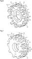
- the motor 1 according to a second embodiment will now be described with reference to Figs. 9 to 12 .
- the motor 1 of the present embodiment differs from the motor 1 of the first embodiment in the structure of the interphase insulating member.
- like or the same reference numerals are given to those components that have the same functions as the corresponding components of the motor 1 according to the first embodiment. The functions of the components will not be described.
- the motor 1 shown in Fig. 9 does not include the rotor 50.
- the stator 10 includes the stator iron cores 11 stacked in the axial direction and interphase insulating members 80 each arranged between the corresponding stator iron cores 11.
- Each interphase insulating member 80 is non-magnetic.
- the interphase insulating member 80 is made of, for example, plastic.
- Each interphase insulating member 80 is arranged between the stator iron cores 11 adjacent to each other in the axial direction such that one of the stator iron cores 11 is insulated from the other one of the stator iron cores 11.
- the number of the interphase insulating members 80 is determined by the number of the stator iron cores 11. For example, the number of the interphase insulating members 80 is two.
- the insulating member 70 of the present embodiment may have the shape of one of the two pieces into which the interphase insulating member 80 is split along a plane that is orthogonal to the axial direction.
- the insulating member 70 may have the substantially same shape as the interphase insulating member 80 and may have the shape of a flat plate.
- the interphase insulating member 80 includes a through-hole 80A extending through in the axial direction.
- the through-hole 80A forms a part of the through-hole 10A of the stator 10.
- the interphase insulating member 80 includes an insulating portion 81 arranged between adjacent ones of the stator iron cores 11 and supports 82.
- the shape of the insulating portion 81 is substantially the same as the shape of the insulating portion 41 of the first embodiment.
- the supports 82 are arranged on the insulating portion 81 such that the supports 82 are in contact with the stator claw magnetic poles 13 of the stator iron core 11.
- the supports 82 are arranged on the insulating portion 81 such that the supports 82 in at least one of the axial direction and the radial direction.
- the stator claw magnetic poles 13 are in contact with the supports 82 in at least one of the circumferential direction and the radial direction.
- the stator claw magnetic poles 13 are in contact with the supports 82 in the circumferential direction and the radial direction (refer to Fig. 9 ).
- the supports 82 are in contact with one of the first stator claw magnetic poles 22 and the second stator claw magnetic poles 32 of the stator iron cores 11 adjacent to the insulating portion 81 in the circumferential direction and are in contact with the other one of the first stator claw magnetic poles 22 and the second stator claw magnetic poles 32 in the radial direction.
- Each support 82 includes a first support 83 extending in the axial direction from a first surface 81A of the insulating portion 81 in the axial direction and a second support 84 extending in the axial direction from a second surface 81C on a side opposite from the first surface 81A of the insulating portion 81.
- the first support 83 is located at a position that differs from the position of the second support 84 in the circumferential direction.
- the deviations between the first supports 83 and the second supports 84 in the circumferential direction are set in reference to the positions of the stator iron cores 11 of the respective phases in the circumferential direction.
- the stator iron core 11 in contact with the first support 83 and the stator iron core 11 in contact with the second support 84 are the stator iron cores 11 of the phases adjacent to each other in the axial direction.
- the first supports 83 are arranged in the vicinity of an edge 81B of the first surface 81A of the insulating portion 81.
- the first supports 83 are arranged on the first surface 81A such that a specific gap is formed between the first supports 83 and the edge 81B of the first surface 81A in the radial direction.
- the specific gap includes a space in which the tips 24A, 34A of the stator claw magnetic poles 22, 32 can be arranged.
- the number of the first supports 83 is, for example, ten.
- the first supports 83 are laid out, for example, at equal intervals in the circumferential direction in the vicinity of the edge 81B of the first surface 81A of the insulating portion 81.
- the first supports 83 are configured to extend in the circumferential direction.
- the first supports 83 are, for example, columnar.
- the first supports 83 have the shape of a substantially quadrilateral column that tapers toward the rotation axis RA of the rotor 50 in the radial direction.
- Each first support 83 is in contact with the corresponding stator claw magnetic pole 22, 32 of one of the first stator 20 and the second stator 30 on one side surface 83A (hereinafter referred to as the first side surface 83A) in the circumferential direction.
- Each first support 83 is in contact with the corresponding stator claw magnetic pole 22, 32 of the other one of the first stator 20 and the second stator 30 on one side surface 83B on a side opposite from the side surface 83C that is closer to the rotation axis RA in the radial direction (hereinafter referred to as the second side surface 83B).
- the first side surfaces 83A of the first supports 83 are in contact with a first stator claw magnetic pole 22 of the first stator 20 in the circumferential direction. More specifically, the first side surfaces 83A of the first supports 83 are in contact with the first claw magnetic pole 23 of the first stator claw magnetic pole 22 in the circumferential direction. For example, the first claw magnetic pole 23 of the first stator claw magnetic pole 22 is held between the first side surfaces 83A of the first supports 83 that oppose each other in the circumferential direction. Thus, the first stator 20 is positioned in the circumferential direction through the contact between the first stator claw magnetic pole 22 and the first side surfaces 83A of the first supports 83.
- Each first support 83 includes a side surface 83C closer to the rotation axis RA in the radial direction (hereinafter referred to as the third side surface 83C).
- the third side surface 83C is in contact with the first back yoke 21 of the first stator 20.
- the third side surfaces 83C of the first supports 83 are in contact with the outer circumferential surface 21A of the first back yoke 21 in the radial direction.
- the first stator 20 is positioned in the radial direction through the contact between the first back yoke 21 and the first side surfaces 83C of the first supports 83.
- the second side surface 83B of each first support 83 is in contact with the corresponding second stator claw magnetic pole 32 of the second stator 30 in the radial direction. More specifically, the second side surface 83B of the first support 83 is in contact with the tip 34A of the second stator claw magnetic pole 32 in the radial direction. In the example shown in Fig. 12 , the second side surface 83B of the first support 83 is in contact with an inner surface 34D of the second claw magnetic pole 34 including the tip 34A of the second stator claw magnetic pole 32 in the radial direction. The inner surface 34D of the second claw magnetic pole 34 faces the rotation axis RA in the radial direction.
- the tip 34A of the second stator claw magnetic pole 32 is arranged in the above-described specific gap such that the tip 34A is in contact with the second side surface 83B of the first support 83.
- the second stator 30 is positioned in the radial direction through the contact between the second stator claw magnetic pole 32 and the second side surface 83B of the first support 83.
- the second supports 84 are arranged in the vicinity of an edge 81D of the second surface 81C of the insulating portion 81.
- the second supports 84 are arranged on the second surface 81C such that a specific gap is formed between the second supports 84 and the edge 81D of the second surface 81C in the radial direction.
- the number of the second supports 84 is, for example, ten.
- the second supports 84 are laid out, for example, at equal intervals in the circumferential direction in the vicinity of the edge 81D of the second surface 81C of the insulating portion 81.
- the shapes of the second supports 84 are substantially the same as the shapes of the first supports 83.
- Each second support 84 is in contact with the corresponding stator claw magnetic pole 22, 32 of one of the first stator 20 and the second stator 30 on one side surface 84A (hereinafter referred to as the first side surface 84A) in the circumferential direction.
- Each second support 84 is in contact with the corresponding stator claw magnetic pole 22, 32 of the other one of the first stator 20 and the second stator 30 on one side surface 84B on a side opposite from the side surface that is closer to the rotation axis RA in the radial direction (hereinafter referred to as the second side surface 84B).
- the first side surfaces 84A of the second supports 84 are in contact with a second stator claw magnetic pole 32 of the second stator 30 in the circumferential direction.
- the relationship between the first side surfaces 84A of the second supports 84 and the second stator claw magnetic pole 32 is substantially the same as the relationship between the first side surfaces 83A of the first supports 83 and the first stator claw magnetic pole 22.
- the second stator 30 is positioned in the circumferential direction through the contact between the second stator claw magnetic pole 32 and the first side surfaces 84A of the second supports 84.
- Each second support 84 includes a side surface closer to the rotation axis RA in the radial direction (hereinafter referred to as the third side surface).
- the third side surface is in contact with the second back yoke 31 of the second stator 30.
- the relationship between the third side surface of the second support 84 is substantially the same as the relationship between the third side surface 83C of the first support 83 and the first back yoke 21.
- the second stator 30 is positioned in the radial direction through the contact between the second back yoke 31 and the third side surfaces of the second supports 84.
- each second support 84 is in contact with the corresponding first stator claw magnetic pole 22 of the first stator 20 in the radial direction.
- the relationship between the second side surface 84A of the second support 84 and the first stator claw magnetic pole 22 is substantially the same as the relationship between the second side surface 83B of the first support 83 and the second stator claw magnetic pole 32.
- the first stator 20 is positioned in the radial direction through the contact between the first stator claw magnetic poles 22 and the second side surfaces 84B of the second supports 84. Accordingly, in the stator iron cores 11 adjacent to each other in the axial direction, one of the stator iron cores 11 is positioned by the first supports 83 and the other one of the stator iron cores 11 is positioned by the second supports 84.
- the insulating portion 81 of the interphase insulating member 80 is in contact with, in the axial direction, the tips 24A, 34A of one of the stator claw magnetic poles 22, 32 extending toward the insulating portion 81 in the first stator claw magnetic poles 22 and the second stator claw magnetic poles 32 of the stator iron core 11 adjacent to the insulating portion 81.
- the first surface 81A of the insulating portion 81 is in contact with the tips 34A of the second stator claw magnetic poles 32 in the axial direction
- the second surface 81C of the insulating portion 41 is in contact with the tips 24A of the first stator claw magnetic poles 22 in the axial direction.
- the insulating portion 81 does not have to be in contact with, in the axial direction, the tips 24A, 34A of one of the stator claw magnetic poles 22, 32 extending toward the insulating portion 81 in the first stator claw magnetic poles 22 and the second stator claw magnetic poles 32 of the stator iron core 11 adjacent to the insulating portion 81.
- the present embodiment provides the following advantage.
- the supports 82 are in contact with one of the first stator claw magnetic poles 22 and the second stator claw magnetic poles 32 of the stator iron cores 11 adjacent to the insulating portion 81 in the circumferential direction and are in contact with the other one of the first stator claw magnetic poles 22 and the second stator claw magnetic poles 32 in the radial direction.
- the first stator 20 is positioned in one of the circumferential direction and the radial direction through the contact between the first stator claw magnetic poles 22 and the supports 82 and the second stator 30 is positioned in the other one of the circumferential direction and the radial direction through the contact between the second stator claw magnetic poles 32 and the supports 82.
- This allows the stator iron cores 11 to be positioned relative to each other in the circumferential direction and the radial direction in a favorable manner.
- the first stator 20 and the second stator 30 are positioned in the circumferential direction and the radial direction without complicating the structure of the stator iron core 11.
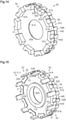
- the motor 1 according to a third embodiment will now be described with reference to Figs. 13 to 16 .
- the motor 1 of the present embodiment differs from the motor 1 of the first embodiment in the structure of the interphase insulating member.
- like or the same reference numerals are given to those components that have the same functions as the corresponding components of the motor 1 according to the first embodiment. The functions of the components will not be described.
- the motor 1 shown in Fig. 13 does not include the rotor 50.
- the stator 10 includes the stator iron cores 11 stacked in the axial direction and interphase insulating members 90 each arranged between the corresponding stator iron cores 11.
- Each interphase insulating member 90 is non-magnetic.
- the interphase insulating member 90 is made of, for example, plastic.
- Each interphase insulating member 90 is arranged between the stator iron cores 11 adjacent to each other in the axial direction such that one of the stator iron cores 11 is insulated from the other one of the stator iron cores 11.
- the number of the interphase insulating members 90 is determined by the number of the stator iron cores 11. For example, the number of the interphase insulating members 90 is two.
- the insulating member 70 of the present embodiment may have the shape of one of the two pieces into which the interphase insulating member 90 is split along a plane that is orthogonal to the axial direction.
- the insulating member 70 may have the substantially same shape as the interphase insulating member 90 and may have the shape of a flat plate.
- the interphase insulating member 90 includes a through-hole 90A extending through in the axial direction.
- the through-hole 90A forms a part of the through-hole 10A of the stator 10.
- the interphase insulating member 90 includes an insulating portion 91 arranged between adjacent ones of the stator iron cores 11 and supports 92.
- the shape of the insulating portion 91 is substantially the same as the shape of the insulating portion 41 of the first embodiment.
- the supports 92 are arranged on the insulating portion 91 such that the supports 92 are in contact with the stator claw magnetic poles 13 of the stator iron core 11.
- the supports 92 are arranged on the insulating portion 91 such that the supports 92 in at least one of the axial direction and the radial direction.
- the stator claw magnetic poles 13 are in contact with the supports 92 in at least one of the circumferential direction and the radial direction.
- the stator claw magnetic poles 13 are in contact with the supports 92 in the circumferential direction and the radial direction (refer to Fig. 13 ).
- the supports 92 are in contact with one of the first stator claw magnetic poles 22 and the second stator claw magnetic poles 32 of the stator iron cores 11 adjacent to the insulating portion 91 in the circumferential direction and are in contact with the other one of the first stator claw magnetic poles 22 and the second stator claw magnetic poles 32 in the circumferential direction and the radial direction.
- Each support 92 includes a first support 93 extending in the axial direction from a first surface 91A of the insulating portion 91 in the axial direction and a second support 94 extending in the axial direction from a second surface 91C on a side opposite from the first surface 91A of the insulating portion 91.
- the first support 93 is located at a position that differs from the position of the second support 94 in the circumferential direction.
- the deviations between the first supports 93 and the second supports 94 in the circumferential direction are set in reference to the positions of the stator iron cores 11 of the respective phases in the circumferential direction.
- the stator iron core 11 in contact with the first support 93 and the stator iron core 11 in contact with the second support 94 are the stator iron cores 11 of the phases adjacent to each other in the axial direction.
- the first supports 93 are arranged on an edge 91B of the first surface 91A of the insulating portion 91.
- the number of the first supports 93 is, for example, ten.
- the first supports 93 are laid out, for example, at equal intervals in the circumferential direction on the edge 91B of the first surface 91A of the insulating portion 91.
- the first supports 93 are, for example, columnar.
- the first supports 93 have the shape of a substantially quadrilateral column that tapers toward the rotation axis RA of the rotor 50 in the radial direction.
- Each first support 93 is in contact with the corresponding stator claw magnetic pole 22, 32 of one of the first stator 20 and the second stator 30 on one side surface 93A (hereinafter referred to as the first side surface 93A) in the circumferential direction.
- Each first support 93 is in contact with the corresponding stator claw magnetic pole 22, 32 of the other one of the first stator 20 and the second stator 30 on one side surface 93B on a side opposite from a side surface 93D that is closer to the rotation axis RA in the radial direction (hereinafter referred to as the second side surface 93B).
- each first support 93 includes a recess 93C in the corresponding second side surface 93B so that the recess 93C is in contact with the stator claw magnetic pole 22, 32 of the other one of the first stator 20 and the second stator 30.
- the recess 93C is recessed from the second side surface 93B so as to accommodate the tip 24A, 34A of the stator claw magnetic pole 22, 32.
- the first side surfaces 93A of the first supports 93 are in contact with a first stator claw magnetic pole 22 of the first stator 20 in the circumferential direction.
- the first stator claw magnetic pole 22 is held between the first side surfaces 93A of the first supports 93 that oppose each other in the circumferential direction.
- the first stator 20 is positioned in the circumferential direction through the contact between the first stator claw magnetic pole 22 and the first side surfaces 93A of the first supports 93.
- Each first support 93 includes the corresponding side surface 93D closer to the rotation axis RA in the radial direction (hereinafter referred to as the third side surface 93D).
- the third side surface 93D is in contact with the first back yoke 21 of the first stator 20.
- the third side surfaces 93D of the first supports 93 are in contact with the outer circumferential surface 21A of the first back yoke 21 in the radial direction.
- the first stator 20 is positioned in the radial direction through the contact between the first back yoke 21 and the first side surfaces 93D of the first supports 93.
- each first support 93 is in contact with the corresponding second stator claw magnetic pole 32 of the second stator 30 in the circumferential direction and the radial direction. More specifically, the recess 93C of each first support 93 is in contact with the tip 34A of the corresponding second stator claw magnetic pole 32 in the circumferential direction and the radial direction. In the example shown in Fig. 16 , the recess 93C of the first support 93 is in contact with the side surface 34C of the second claw magnetic pole 34 including the tip 34A of the second stator claw magnetic pole 32 in the circumferential direction and is in contact with the inner surface 34D of the second claw magnetic pole 34 in the radial direction.
- the tip 34A of the second stator claw magnetic pole 32 is fitted into the recess 93C of the first support 93.
- the second stator 30 is positioned in the circumferential direction and the radial direction through the contact between the second stator claw magnetic pole 32 and the recess 93C of the first support 93.
- the second supports 94 are arranged on an edge 91D of the second surface 91C of the insulating portion 91.
- the number of the second supports 94 is, for example, ten.
- the second supports 94 are laid out, for example, at equal intervals in the circumferential direction on the edge 91D of the second surface 91C of the insulating portion 91.
- the shapes of the second supports 94 are substantially the same as the shapes of the first supports 93.
- Each second support 94 is in contact with the corresponding stator claw magnetic pole 22, 32 of one of the first stator 20 and the second stator 30 on one side surface 94A (hereinafter referred to as the first side surface 94A) in the circumferential direction.
- Each second support 94 is in contact with the corresponding stator claw magnetic pole 22, 32 of the other one of the first stator 20 and the second stator 30 on one side surface 94B on a side opposite from the side surface that is closer to the rotation axis RA in the radial direction (hereinafter referred to as the second side surface 94B).
- each second support 94 includes a recess 94C in the corresponding second side surface 94B so that the recess 94C is in contact with the stator claw magnetic pole 22, 32 of the other one of the first stator 20 and the second stator 30.
- the recess 94C is recessed from the second side surface 94B so as to accommodate the tip 24A, 34A of the stator claw magnetic pole 22, 32.
- the first side surfaces 94A of the second supports 94 are in contact with a second stator claw magnetic pole 32 of the second stator 30 in the circumferential direction.
- the relationship between the first side surfaces 94A of the second supports 94 and the second stator claw magnetic pole 32 is substantially the same as the relationship between the first side surfaces 93A of the first supports 93 and the first stator claw magnetic pole 22.
- the second stator 30 is positioned in the circumferential direction through the contact between the second stator claw magnetic pole 32 and the first side surfaces 94A of the second supports 94.
- Each second support 94 includes a side surface closer to the rotation axis RA in the radial direction (hereinafter referred to as the third side surface).
- the third side surface is in contact with the second back yoke 31 of the second stator 30.
- the relationship between the third side surface of the second support 94 is substantially the same as the relationship between the third side surface 93D of the first support 93 and the first back yoke 21.
- the second stator 30 is positioned in the radial direction through the contact between the second back yoke 31 and the third side surface of the second support 94.
- each second support 94 is in contact with the corresponding first stator claw magnetic pole 22 of the first stator 20 in the circumferential direction and the radial direction.
- the relationship between the recess 94C of the second support 94 and the first stator claw magnetic pole 22 is substantially the same as the relationship between the recess 93C of the first support 93 and the first stator claw magnetic pole 32.
- the first stator 20 is positioned in the circumferential direction and the radial direction through the contact between the first stator claw magnetic pole 22 and the recess 94C of the second support 94. Accordingly, in the stator iron cores 11 adjacent to each other in the axial direction, one of the stator iron cores 11 is positioned by the first supports 93 and the other one of the stator iron cores 11 is positioned by the second supports 94.
- the insulating portion 91 of the interphase insulating member 90 is in contact with, in the axial direction, the tips 24A, 34A of one of the stator claw magnetic poles 22, 32 extending toward the insulating portion 91 in the first stator claw magnetic poles 22 and the second stator claw magnetic poles 32 of the stator iron core 11 adjacent to the insulating portion 91.
- the first surface 91A of the insulating portion 91 is in contact with the tips 34A of the second stator claw magnetic poles 32 in the axial direction
- the second surface 91C of the insulating portion 41 is in contact with the tips 24A of the first stator claw magnetic poles 22 in the axial direction.
- the insulating portion 91 does not have to be in contact with, in the axial direction, the tips 24A, 34A of one of the stator claw magnetic poles 22, 32 extending toward the insulating portion 91 in the first stator claw magnetic poles 22 and the second stator claw magnetic poles 32 of the stator iron core 11 adjacent to the insulating portion 91.
- the present embodiment provides the following advantage.
- the supports 92 are in contact with one of the first stator claw magnetic poles 22 and the second stator claw magnetic poles 32 of the stator iron cores 11 adjacent to the insulating portion 91 in the circumferential direction and are in contact with the other one of the first stator claw magnetic poles 22 and the second stator claw magnetic poles 32 in the circumferential direction and the radial direction.
- one of the first stator 20 and the second stator 30 is positioned in the circumferential direction through the contact between the first stator claw magnetic poles 22, 32 and the supports 92 and the other one of the first stator 20 and the second stator 30 is positioned in the circumferential direction and the radial direction through the contact between the second stator claw magnetic poles 22, 32 and the supports 92.
- This allows the stator iron cores 11 to be positioned relative to each other in the circumferential direction and the radial direction in a favorable manner.
- the first stator 20 and the second stator 30 are positioned in the circumferential direction and the radial direction without complicating the structure of the stator iron core 11.
- the motor 1 according to a fourth embodiment will now be described with reference to Fig. 17 .
- the motor 1 of the present embodiment differs from the motor 1 of the first embodiment in the structure of the fixing member 60.
- like or the same reference numerals are given to those components that have the same functions as the corresponding components of the motor 1 according to the first embodiment. The functions of the components will not be described.
- Fig. 17 shows the cross-section of the motor 1 without the rotor 50.
- the fixing member 60 includes the first end plate 61, the second end plate 62, and rod portions 64.
- Each rod portion 64 is insertable into the through-hole 10A of the stator 10.
- the number of the rod portions 64 is, for example, four.
- the rod portions 64 are spaced apart from each other in the circumferential direction.
- the rod portions 64 are arranged at equal intervals in the circumferential direction.
- the rod portions 64 and the first and second end plates 61, 62 are fixed with the rod portions 64 inserted into the through-hole 10A of the stator 10 and the stator 10 held between the first end plate 61 and the second end plate 62 in the axial direction.
- the first end plate 61, the second end plate 62, and the rod portions 64 are separate from each other.
- the number of the rod portions 64 may be less than or equal to three or may be greater than or equal to five.
- the rod portions 64 each include a thread groove 64A.
- the thread groove 64A is formed on an outer circumferential surface 64B of the rod portion 64.
- the thread groove 64A is formed on a tip 64C of the rod portion 64.
- the rod portions 64 of the present embodiment are bolts.
- Each rod portion 64 opposes the inner surface 10D of the through-hole 10A of the stator 10 in the radial direction with the gap S located in between.
- At least one of the first end plate 61 and the second end plate 62 includes a thread groove 62C that can be threaded to the thread groove 64A of each rod portion 64.
- the first end plate 61 includes insertion through-holes 61A through which the rod portions 64 are insertable.
- the second end plate 62 includes insertion holes 62D into which the rod portions 64 are insertable, instead of the insertion hole 62B of the first embodiment.
- each of the insertion holes 62D of the second end plate 62 includes the corresponding thread groove 62C.
- the rod portions 64 are fixed to the second end plate 62 by inserting the rod portions 64 into the insertion holes 62D of the second end plate 62 through the insertion through-holes 61A of the first end plate 61 and through the through-hole 10A of the stator 10 and fastening the thread grooves 64A of the rod portions 64 to the thread grooves 62C of the second end plate 62.
- the stator 10 is fixed so as to be held between the first end plate 61 and the second end plate 62.
- the present embodiment provides the following advantage.
- the rod portions 64 are spaced apart from each other in the circumferential direction.
- the rod portions 64 are inserted into the through-hole 10A of the stator 10 to fix the rod portions 64 and the first and second end plates 61, 62. Accordingly, the stator 10 is fixed securely.
- the motor 1 according to a fifth embodiment will now be described with reference to Fig. 18 .
- the motor 1 of the present embodiment differs from the motor 1 of the first embodiment in the structure of the fixing member 60.
- like or the same reference numerals are given to those components that have the same functions as the corresponding components of the motor 1 according to the first embodiment. The functions of the components will not be described.
- Fig. 18 shows the cross-section of the motor 1 without the rotor 50.
- the fixing member 60 includes the first end plate 61, the second end plate 62, and one or more rod portions 63. At least one of the first end plate 61 and the second end plate 62 includes a through-hole 62E that extends through in the axial direction such that the rod portion 63 is insertable through the through-hole 62E.
- the second end plate 62 includes the through-hole 62E, instead of the insertion hole 62B of the first embodiment.
- the fixing member 60 further includes a holding portion 65 with a thread groove 65A. The thread groove 65A of the holding portion 65 is capable of being fastened to the thread groove 63A of the rod portion 63.
- the holding portion 65 is arranged so as to oppose the stator 10 with at least one of the first end plate 61 and the second end plate 62 located in between.
- the holding portion 65 is arranged so as to oppose the stator 10 with the second end plate 62 located in between.
- the holding portion 65 of the present embodiment is a nut.
- the rod portion 63 has a specific length in the axial direction.
- the length of the rod portion 63 in the axial direction may be set to be greater than the sum of the thickness of the stator 10 in the axial direction and the thickness of the second end plate 62 in the axial direction.
- the length of the rod portion 63 in the axial direction is preferably set to be less than or equal to the sum of the thickness of the stator 10 in the axial direction, the thickness of the second end plate 62 in the axial direction, and the thickness of the holding portion 65 in the axial direction.
- the length of the rod portion 63 in the axial direction is set so as to coincide with the sum of the thickness of the stator 10 in the axial direction, the thickness of the second end plate 62 in the axial direction, and the thickness of the holding portion 65 in the axial direction.
- the length of the rod portion 63 in the axial direction may be set to be greater than the sum of the thickness of the stator 10 in the axial direction, the thickness of the second end plate 62 in the axial direction, and the thickness of the holding portion 65 in the axial direction.
- the rod portion 63 and the holding portion 65 are fixed by inserting the rod portion 63 into the through-hole 10A of the stator 10 and the through-hole 62E of the second end plate 62 and fastening the thread groove 65A of the holding portion 65 to the thread groove 63A of the rod portion 63 that protrudes from the through-hole 62E of the second end plate 62.
- the stator 10 is fixed so as to be held between the first end plate 61 and the second end plate 62.
- the present embodiment provides the following advantage.
- the thread groove 63A of the rod portion 63 inserted into the through-hole 10A of the stator 10 is inserted through the through-hole 62E of the second end plate 62 and fastened to the thread groove 65A of the holding portion 65. This allows the stator 10 to be fixed with a simple structure.
- the motor 1 according to a sixth embodiment will now be described with reference to Fig. 19 .
- the motor 1 of the present embodiment differs from the motor 1 of the first embodiment in the structure of the fixing member 60.
- like or the same reference numerals are given to those components that have the same functions as the corresponding components of the motor 1 according to the first embodiment. The functions of the components will not be described.
- Fig. 19 shows the cross-section of the motor 1 without the rotor 50.
- the fixing member 60 includes the first end plate 61, the second end plate 62, and one or more rod portions 63. At least one of the first end plate 61 and the second end plate 62 includes a hole 62F in the axial direction such that the rod portion 63 is insertable into the hole 62F.
- the second end plate 62 includes the hole 62F, instead of the insertion hole 62B of the first embodiment. It is preferred that the rod portion 63 does not include the thread groove 63A.
- the rod portion 63 and at least one of the first end plate 61 and the second end plate 62 are fixed in accordance with, for example, the following first or second example.
- the rod portion 63 is engaged with the hole 62F of at least one of the first end plate 61 and the second end plate 62 through press-fitting, shrink-fitting, or cool-fitting.
- the rod portion 63 is engaged with the hole 62F of the second end plate 62 through press-fitting, shrink-fitting, or cool-fitting.
- the rod portion 63 is bonded, welded, or fused to the hole 62F of at least one of the first end plate 61 and the second end plate 62.
- the rod portion 63 is bonded, welded, or fused to the second end plate 62.
- the rod portion 63 may be bonded, welded, or fused to the hole 62F of the second end plate 62.
- the second end plate 62 does not have to include the hole 62F.
- the present embodiment provides the following advantages.
- the stator 10 is fixed by engaging the rod portion 63 inserted into the through-hole 10A of the stator 10 with the hole 62F of the second end plate 62 through press-fitting, shrink-fitting, or cool-fitting. This structure allows the stator 10 to be fixed securely.
- stator 10 is fixed by bonding, welding, or fusing the rod portion 63 inserted into the through-hole 10A of the stator 10 to the hole 62F. This structure allows the stator 10 to be fixed securely.
- the motor 1 according to a seventh embodiment will now be described with reference to Fig. 20 .
- the motor 1 of the present embodiment differs from the motor 1 of the first embodiment in the structure of the rod portion 63.
- like or the same reference numerals are given to those components that have the same functions as the corresponding components of the motor 1 according to the first embodiment. The functions of the components will not be described.
- the rod portion 63 includes an internal space 63D.
- the rod portion 63 includes through portions 63F that extend in the radial direction through the outer circumferential surface 63B of the rod portion 63 and an inner circumferential surface 63E.
- the inner circumferential surface 63E defines the internal space 63D.
- the through portions 63F are, for example, slits extending in the axial direction.
- the through portions 63F are each sized such that the coil 14 of the stator 10 can be drawn out of the through portion 63F.
- the number of the through portions 63F is, for example, two.
- the two through portions 63F are, for example, arranged in the rod portion 63 so as to oppose each other in the radial direction.
- the through portions 63F are continuously arranged in the first end plate 61 and the rod portion 63.
- the through portions 63F may be arranged only in the rod portion 63.
- the present embodiment provides the following advantage.
- the rod portion 63 includes the through portions 63F extending in the radial direction through the outer circumferential surface 63B and the inner circumferential surface 63E, which defines the internal space 63D. This structure allows the coil 14 of the stator 10 to be easily drawn out of the through portions 63F. Additionally, the motor 1 has a reduced weight.
- the above-described embodiments exemplify, without any intention to limit, an applicable form of a stator and a motor including the stator related to the present invention.
- the stator and the motor including the stator related to the present disclosure can take a form different from the form illustrated in the embodiment.
- some of the components of the above-described embodiments may be replaced, changed, or omitted.
- another component may be added to the above-described embodiments.
- the same reference characters are given to those elements that are the same as the corresponding elements of the above-described embodiments. Such elements will not be described in detail.
- each first stator claw magnetic pole 22 of the first stator 20 includes a tapered tip 24A.
- the tip 24A of each first stator claw magnetic pole 22 is tapered in the circumferential direction.
- the same modification is applied to the second stator 30.
- each first stator claw magnetic pole 22 of the first stator 20 does not include the corresponding second claw magnetic pole 24.
- each second stator claw magnetic pole 32 preferably includes the corresponding first claw magnetic pole 33 and the corresponding second claw magnetic pole 34.
- each first stator claw magnetic pole 22 of the first stator 20 further includes a third claw magnetic pole 25 in addition to the corresponding first claw magnetic pole 23 and the corresponding second claw magnetic pole 24.
- the third claw magnetic pole 25 extends, for example, in the axial direction from the first claw magnetic pole 23 toward a side opposite from the second claw magnetic pole 24.
- the length of the third claw magnetic pole 25 in the axial direction is shorter than the length of the second claw magnetic pole 24 in the axial direction.
- the stator iron cores 11 are each formed using a magnetic steel sheet.
- each stator iron core 11 does not include the through-hole 11A.
- the stator 10 is fixed using a fixing member that differs from the fixing member 60.
- the stator iron core 11 may be manufactured through molding.
- the through-hole 70A does not have to include the through-hole 70A.
- the interphase insulating members 40, 80, 90 do not have to include the through-holes 40A, 80A, 90A, respectively.
- each stator 10 may be changed.
- the stator 10 is a claw-pole stator having two or less phases or having four or more phases.
- the number of the stator iron cores 11 is two or is or four or more.
- the stator 10 does not include the fixing member 60.
- the stator iron core 11 is, for example, press-fitted to a support member that is insertable through the through-hole 10A of the stator 10.
- the structure of the motor 1 may be changed.
- the motor 1 is an inner rotor motor.
Landscapes
- Engineering & Computer Science (AREA)
- Power Engineering (AREA)
- Iron Core Of Rotating Electric Machines (AREA)
Abstract
Description
- The present disclosure relates to a stator and a motor including the stator.
-
Patent Document 1 discloses a motor including a three-phase claw pole stator. In the motor, the stator iron cores of the respective phases of the stator in the circumferential direction of the rotor are stacked such that the positions of the stator iron cores of the phases of electrical angles are different from each other by 120°. A circular coupling plate made of a non-magnetic plastic material is arranged between the stator iron cores of the phases. The stator iron core of each phase is positioned by the coupling plate. - Patent Document 1:
Japanese Laid-Open Patent Publication No. 2008-148397 - In the stator of
Patent Document 1, one side surface of the coupling plate includes a projection, and one side surface of each stator iron core includes a recess. The stator iron core is positioned relative to the coupling plate by engaging the projection with the recess. The projections of the coupling plate are arranged on the opposite sides of the coupling plate. Thus, the positioning of the stator iron cores of the respective phases relative to the coupling plate causes the stator iron cores to be positioned relative to each other. However, to position the stator iron cores of the phases, each stator iron core needs a recess. This complicates the structure of the stator iron core. - It is an object of the present disclosure to provide a stator capable of positioning stator iron cores relative to each other without complicating the structure of each stator iron core and provide a motor including the stator.
- A stator that solves the problem includes: stator iron cores stacked in an axial direction of a rotor; and an interphase insulating member arranged between the stator iron cores. The stator iron cores each include a circular back yoke and a stator claw magnetic pole that protrudes from the back yoke in a radial direction of the rotor. The interphase insulating member includes an insulating portion, arranged between adjacent ones of the stator iron cores, and a support. The stator claw magnetic pole is in contact with the support in at least one of a circumferential direction of the rotor and the radial direction of the rotor.
- In this structure, each stator iron core is positioned through the contact between the stator claw magnetic pole and the support in at least one of the circumferential direction of the rotor and the radial direction of the rotor. This allows the stator iron cores to be positioned relative to each other without complicating the structures of the stator iron cores.
- In the above-described stator, it is preferred that the support include a first support extending in the axial direction of the rotor from a first surface of the insulating portion in the axial direction of the rotor and a second support extending in the axial direction of the rotor from a second surface on a side opposite from the first surface of the insulating portion and that the first support be located at a position that differs from a position of the second support in the circumferential direction of the rotor.
- In this structure, one of the stator iron cores adjacent to the interphase insulating member is positioned through the contact between the stator claw magnetic pole and the first support, and the other one of the stator iron cores adjacent to the interphase insulating member is positioned through the contact between the stator claw magnetic pole and the second support. This allows the stator iron cores to be positioned relative to each other with the positions of the stator iron cores located at different positions in the circumferential direction of the rotor.
- In the above-described stator, it is preferred that the stator iron cores each include a first stator and a second stator, that the first stator include a circular first back yoke and a first stator claw magnetic pole that protrudes from the first back yoke in the radial direction of the rotor and that the second stator include a circular second back yoke and a second stator claw magnetic pole that protrudes from the second back yoke in the radial direction of the rotor. This structure simplifies the structures of the stator iron cores.
- In the above-described stator, it is preferred that the first stator claw magnetic pole protrude from the first back yoke in the radial direction of the rotor and extends at least toward the second stator in the axial direction of the rotor and that the second stator claw magnetic pole protrude from the second back yoke in the radial direction of the rotor, and extend at least toward the first stator in the axial direction of the rotor such that a void is created between the first stator claw magnetic pole and the second stator claw magnetic pole in the circumferential direction of the rotor.
- In this structure, the stator iron core is configured such that the first stator claw magnetic pole and the second stator claw magnetic pole are laid out in the circumferential direction of the rotor. This structure increases the areas of the stator iron cores opposing the rotor and thus contributes to generating torque in a stable manner.
- In the above-described stator, it is preferred that the insulating portion be in contact with, in the axial direction of the rotor, a tip of one of the stator claw magnetic poles extending toward the insulating portion in the first stator claw magnetic pole and the second stator claw magnetic pole of the stator iron core adjacent to the insulating portion.
- In this structure, the tip of one of the first and second stator claw magnetic poles is supported by the insulating portion in the axial direction of the rotor so as to reinforce the stator claw magnetic pole. This improves the strength of the stator iron core.
- In the above-described stator, it is preferred that the support be in contact with, in the circumferential direction of the rotor, the first stator claw magnetic pole and the second stator claw magnetic pole of the stator iron core adjacent to the insulating portion.
- In this structure, in the stator iron core adjacent to the insulating portion, the first stator is positioned in the circumferential direction of the rotor through the contact between the first stator claw magnetic pole and the support and the second stator is positioned in the circumferential direction of the rotor through the contact between the second stator claw magnetic pole and the support. This allows the first stator and the second stator to be positioned relative to each other in the circumferential direction of the rotor.
- In the above-described stator, it is preferred that the support be in contact with, in the circumferential direction of the rotor, one of the first stator claw magnetic pole and the second stator claw magnetic pole of the stator iron core adjacent to the insulating portion and be in contact with, in the radial direction of the rotor, the other one of the first stator claw magnetic pole and the second stator claw magnetic pole.
- In this structure, in the stator iron core adjacent to the insulating portion, the first stator is positioned in one of the circumferential direction of the rotor and the radial direction of the rotor through the contact between the first stator claw magnetic pole and the support and the second stator is positioned in the other one of the circumferential direction of the rotor and the radial direction of the rotor through the contact between the second stator claw magnetic pole and the support. This allows the first stator and the second stator to be positioned relative to each other in the circumferential direction of the rotor and the radial direction of the rotor.
- In the above-described stator, it is preferred that the stator iron cores be each formed using a powder magnetic core.
- This structure prevents the generation of eddy currents and thus contributes to reducing eddy-current losses. Additionally, the degree of freedom in the shape of the stator iron core improves.
- A motor that solves the above-described problem includes the stator and the rotor.
- In this structure, each stator iron core is positioned through the contact between the stator claw magnetic pole and the support in at least one of the circumferential direction of the rotor and the radial direction of the rotor. This allows the stator iron cores to be positioned relative to each other without complicating the structures of the stator iron cores.
-
-
Fig. 1 is a perspective view showing a motor according to a first embodiment. -
Fig. 2 is a perspective view showing the motor inFig. 1 without the rotor. -
Fig. 3 is an exploded perspective view showing the motor inFig. 2 . -
Fig. 4 is an exploded perspective view showing one of the stator iron cores inFig. 3 . -
Fig. 5 is a perspective view showing one of the interphase insulating members inFig. 3 . -
Fig. 6 is a perspective view showing the relationship between the interphase insulating member inFig. 5 and the first stator. -
Fig. 7 is a perspective view showing the relationship between the interphase insulating member inFig. 5 and the second stator. -
Fig. 8 is a cross-sectional view taken along the axial direction of the rotor in the motor inFig. 2 . -
Fig. 9 is a perspective view showing a motor according to a second embodiment. -
Fig. 10 is a perspective view showing one of the interphase insulating members inFig. 9 . -
Fig. 11 is a perspective view showing the relationship between the interphase insulating member inFig. 10 and the first stator. -
Fig. 12 is a perspective view showing the relationship between the interphase insulating member inFig. 10 and the second stator. -
Fig. 13 is a perspective view showing a motor according to a third embodiment. -
Fig. 14 is a perspective view showing one of the interphase insulating members inFig. 13 . -
Fig. 15 is a perspective view showing the relationship between the interphase insulating member inFig. 14 and the first stator. -
Fig. 16 is a perspective view showing the relationship between the interphase insulating member inFig. 14 and the second stator. -
Fig. 17 is a cross-sectional view taken along the axial direction of the rotor in the motor according to a fourth embodiment. -
Fig. 18 is a cross-sectional view taken along the axial direction of the rotor in the motor according to a fifth embodiment. -
Fig. 19 is a cross-sectional view taken along the axial direction of the rotor in the motor according to a sixth embodiment. -
Fig. 20 is a perspective view showing the rod portion according to a seventh embodiment. -
Fig. 21 is a perspective view showing the first stator of the stator iron core according to a modification. -
Fig. 22 is a perspective view showing the first stator of the stator iron core according to a modification. -
Fig. 23 is a perspective view showing the first stator of the stator iron core according to a modification. - A
motor 1 according to a first embodiment will now be described. The scope of the present disclosure is defined not by the detailed description but by the claims and their equivalents, and all variations within the scope of the claims and their equivalents are to be construed as being included in the disclosure. - As shown in
Fig. 1 , themotor 1 is of an outer-rotor type. Themotor 1 is installed in, for example, an air conditioner (not shown). For example, themotor 1 is capable of driving a sirocco fan (not shown) installed in the air conditioner. Themotor 1 includes a claw-pole stator 10 (hereinafter referred to as the stator 10), arotor 50 capable of rotating relative to thestator 10, and a fixingmember 60 capable of fixing thestator 10. - The
rotor 50 includes a rotation axis RA. Therotor 50 is capable of rotating about the rotation axis RA. Therotor 50 includesrotor iron cores 51 stacked in the axial direction of the rotation axis RA andmagnets 52 arranged on an innercircumferential surface 51A of eachrotor iron core 51. The axial direction of the rotation axis RA coincides with the axial direction of the rotor 50 (hereinafter referred to as the axial direction). Eachrotor iron core 51 is, for example, annular. The number of therotor iron cores 51 coincides with the number of stator iron cores 11 (refer toFig. 2 ) included in thestator 10. For example, the number of therotor iron cores 51 is three. Themagnets 52 are, for example, laid out on the innercircumferential surface 51A of eachrotor iron core 51 in the circumferential direction so as to oppose an outercircumferential surface 11D (refer toFig. 2 ) of the correspondingstator iron core 11. For example, twentymagnets 52 are laid out in the circumferential direction of the rotation axis RA on the innercircumferential surface 51A of eachrotor iron core 51. The circumferential direction of the rotation axis RA coincides with the circumferential direction of the rotor 50 (hereinafter referred to as the circumferential direction). Themagnets 52 are, for example, permanent magnets. - As shown in
Fig. 2 , thestator 10 includes thestator iron cores 11 stacked in the axial direction and interphase insulatingmembers 40 each arranged between the correspondingstator iron cores 11. Thestator iron cores 11 are each formed using a powder magnetic core. The number of thestator iron cores 11 is two or more. For example, the number of thestator iron cores 11 is three. Thestator 10 of the present embodiment is a three-phase claw-pole stator with a three-dimensional magnetic structure in which thestator iron cores 11 are stacked in the order of U-phase, V-phase, and W-phase. In the example shown inFig. 2 , thestator iron cores 11 of the respective phases in the circumferential direction are stacked such that the positions of thestator iron cores 11 of the phases of electrical angles are different from each other by 120°. - Each
interphase insulating member 40 is non-magnetic. Theinterphase insulating member 40 is made of, for example, plastic. Eachinterphase insulating member 40 is arranged between ones of thestator iron cores 11 adjacent to each other in the axial direction such that one of thestator iron cores 11 is insulated from the other one of thestator iron cores 11. The number of theinterphase insulating members 40 is determined by the number of thestator iron cores 11. For example, the number of theinterphase insulating members 40 is two. The dotted parts inFig. 2 illustrate theinterphase insulating members 40. - As shown in
Fig. 3 , thestator 10 further includes an insulatingmember 70 arranged between thestator iron cores 11 and the fixingmember 60. The insulatingmember 70 is non-magnetic. The insulatingmember 70 is made of, for example, plastic. The insulatingmember 70 is arranged between thestator iron cores 11 and the fixingmember 60 such that thestator iron cores 11 and the fixingmember 60 are insulated from each other. The insulatingmember 70 is arranged in at least one of a section between thestator iron cores 11 and afirst end plate 61 of the fixingmember 60 and a section between thestator iron cores 11 and asecond end plate 62 of the fixingmember 60 in the axial direction. In the example shown inFig. 3 , the insulatingmember 70 is arranged between thestator iron cores 11 and thefirst end plate 61 of the fixingmember 60. - The insulating
member 70 has the shape of one of the two pieces into which each interphase insulatingmember 40 is split along a plane that is orthogonal to the axial direction. In this case, the insulatingmember 70 includes aflat end surface 71 opposing thefirst end plate 61 of the fixingmember 60. Theend surface 71 of the insulatingmember 70 defines oneend surface 10B of thestator 10. The insulatingmember 70 may have the substantially same shape as theinterphase insulating member 40 and may have the shape of a flat plate. The shape of one of the two pieces into which theinterphase insulating member 40 is split along the plane that is orthogonal to the axial direction may be formed on a portion of thesecond end plate 62 opposing thestator iron cores 11. Thestator 10 does not have to include the insulatingmember 70. In this example, theend surface 10B of thestator 10 is formed by anend surface 11B of the U-phasestator iron core 11 opposing thefirst end plate 61 of the fixingmember 60. - The
stator 10 includes a through-hole 10A extending through in the axial direction. For example, eachstator iron core 11 includes a through-hole 11A extending through in the axial direction, each interphase insulatingmember 40 includes a through-hole 40A extending through in the axial direction, the insulatingmember 70 includes a through-hole 70A extending through in the axial direction. The through-hole 11A of eachstator iron core 11, the through-hole 40A of each interphase insulatingmember 40, and the through-hole 70A of the insulatingmember 70 form the through-hole 10A of thestator 10. The through-hole 11A of eachstator iron core 11, the through-hole 40A of each interphase insulatingmember 40, and the through-hole 70A of the insulatingmember 70 have the substantially same size. - The fixing
member 60 includes thefirst end plate 61, thesecond end plate 62, and one ormore rod portions 63. Thefirst end plate 61 has the shape of, for example, a circular plate. Thefirst end plate 61 is arranged in contact with theend surface 10B in the axial direction. For example, thefirst end plate 61 is arranged in contact with theend surface 71 of the insulatingmember 70. In an example in which thestator 10 does not include the insulatingmember 70, thefirst end plate 61 is arranged in contact with theend surface 11B of the U-phasestator iron core 11. Thesecond end plate 62 has the shape of, for example, a circular plate. For example, thesecond end plate 62 has the shape of a circular plate with a larger diameter than thefirst end plate 61. Thesecond end plate 62 is arranged in contact with theother end surface 10C (refer toFig. 8 ) in the axial direction in thestator 10. Theother end surface 10C of thestator 10 is defined by anend surface 11C (refer toFig. 8 ) of the W-phasestator iron core 11. For example, thesecond end plate 62 is arranged in contact with theend surface 11C of the W-phasestator iron core 11. - The
rod portion 63 is insertable into the through-hole 10A of thestator 10. Therod portion 63 and the first andsecond end plates rod portion 63 inserted into the through-hole 10A of thestator 10 and thestator 10 held between thefirst end plate 61 and thesecond end plate 62 in the axial direction. One of thefirst end plate 61 and thesecond end plate 62 is formed integrally with therod portion 63. Therod portion 63 of the present embodiment is formed integrally with thefirst end plate 61. Therod portion 63 may be formed integrally with thesecond end plate 62. - The
rod portion 63 includes athread groove 63A. Thethread groove 63A is formed on an outercircumferential surface 63B of therod portion 63. For example, thethread groove 63A is formed on atip 63C of therod portion 63. At least one of thefirst end plate 61 and thesecond end plate 62 includes athread groove 62A that can be threaded to thethread groove 63A of therod portion 63. Thesecond end plate 62 includes aninsertion hole 62B into which therod portion 63 is insertable. Theinsertion hole 62B extends through, for example, in the axial direction. Theinsertion hole 62B does not have to extend through in the axial direction. Thethread groove 62A is formed in theinsertion hole 62B of thesecond end plate 62. When the fixingmember 60 includes more than onerod portions 63, thefirst end plate 61 and thesecond end plate 62 may both include thethread groove 62A. Therod portion 63 is fixed to thesecond end plate 62 by inserting therod portion 63 into theinsertion hole 62B of thesecond end plate 62 through the through-hole 10A of thestator 10 and fastening thethread groove 63A of therod portion 63 to thethread groove 62A of thesecond end plate 62. Thus, thestator 10 is fixed so as to be held between thefirst end plate 61 and the second end plate 62 (refer toFig. 8 ). - The structure of each
stator iron core 11 will now be described with reference toFig. 4 . - The
stator iron core 11 includes acircular back yoke 12 and stator clawmagnetic poles 13 that protrude from theback yoke 12 in the radial direction of the rotor 50 (hereinafter referred to as the radial direction). Theback yoke 12 of the present embodiment is annular. The through-hole 11A of thestator iron core 11 is formed in theback yoke 12. In other words, theback yoke 12 includes the through-hole 11A. The stator clawmagnetic poles 13 protrude in the radial direction from an outercircumferential surface 12A of theback yoke 12 and extends in the axial direction. - The
stator iron core 11 includes afirst stator 20 and asecond stator 30. Thefirst stator 20 includes a circularfirst back yoke 21 and first stator clawmagnetic poles 22 that protrude from thefirst back yoke 21 in the radial direction. Thefirst back yoke 21 of the present embodiment is annular. Thefirst back yoke 21 is included in theback yoke 12. The first stator clawmagnetic poles 22 protrude from thefirst back yoke 21 in the radial direction and extend at least toward thesecond stator 30 in the axial direction. For example. the first stator clawmagnetic poles 22 protrude from the outercircumferential surface 21A of thefirst back yoke 21 in the radial direction and extend toward thesecond stator 30 in the axial direction. The first stator clawmagnetic poles 22 are included in the stator clawmagnetic poles 13. The number of the first stator clawmagnetic poles 22 is, for example, ten. The first stator clawmagnetic poles 22 are arranged, for example, at equal intervals in the circumferential direction on the outercircumferential surface 21A of thefirst back yoke 21. - Each first stator claw
magnetic pole 22 includes a first clawmagnetic pole 23 and a second clawmagnetic pole 24. The first clawmagnetic pole 23 is a portion including the root of the first stator clawmagnetic pole 22. The first clawmagnetic pole 23 extends in the radial direction from the outercircumferential surface 21A of thefirst back yoke 21. The second clawmagnetic pole 24 is a portion including atip 24A of the first stator clawmagnetic pole 22. The second clawmagnetic pole 24 extends from the first clawmagnetic pole 23 toward thesecond stator 30. The second clawmagnetic pole 24 has, for example, a parallelepiped shape. For example, anouter surface 24B of each second clawmagnetic pole 24, which is a part of the outercircumferential surface 11D of thestator iron core 11, opposes thecorresponding magnet 52 of therotor 50. - The
second stator 30 has, for example, the substantially same structure as thefirst stator 20. Thesecond stator 30 includes a circularsecond back yoke 31 and second stator clawmagnetic poles 32 that protrude from thesecond back yoke 31 in the radial direction. Thesecond back yoke 31 of the present embodiment is annular. Thesecond back yoke 31 is included in theback yoke 12. Each second stator clawmagnetic pole 32 protrudes from thesecond back yoke 31 in the radial direction, and extends at least toward thefirst stator 20 in the axial direction such that a void G (refer toFig. 3 ) is created between the first stator clawmagnetic pole 22 and the second stator clawmagnetic pole 32 in the circumferential direction. For example, the second stator clawmagnetic poles 32 protrude from the outercircumferential surface 31A of thesecond back yoke 31 in the radial direction and extend toward thefirst stator 20 in the axial direction. The second stator clawmagnetic poles 32 are included in the stator clawmagnetic poles 13. The number of the second stator clawmagnetic poles 32 is, for example, ten. The second stator clawmagnetic poles 32 are arranged, for example, at equal intervals in the circumferential direction on the outercircumferential surface 31A of thesecond back yoke 31. - Each second stator claw
magnetic pole 32 includes a first clawmagnetic pole 33 and a second clawmagnetic pole 34. The first clawmagnetic pole 33 is a portion including the root of the second stator clawmagnetic pole 32. The first clawmagnetic pole 33 extends in the radial direction from the outercircumferential surface 31A of thesecond back yoke 31. The second clawmagnetic pole 34 is a portion including atip 34A of the second stator clawmagnetic pole 32. The second clawmagnetic pole 34 extends from the first clawmagnetic pole 33 toward thefirst stator 20 such that the void G is created between the second clawmagnetic pole 34 and the second clawmagnetic pole 24 of the first stator clawmagnetic pole 22 in the circumferential direction. The second clawmagnetic pole 34 has, for example, a parallelepiped shape. For example, anouter surface 34B of each second clawmagnetic pole 34, which is a part of the outercircumferential surface 11D of thestator iron core 11, opposes thecorresponding magnet 52 of therotor 50. - The
stator 10 further includes acoil 14 wound around in an annular manner. Thecoil 14 is connected to, for example, an inverter circuit or a current conversion circuit (not shown). Thecoil 14 is arranged between thefirst stator 20 and thesecond stator 30 in the axial direction. For example, thecoil 14 is arranged between thefirst stator 20 and thesecond stator 30 in the circumferential direction, and thestator iron core 11 is formed by coupling thefirst stator 20 to thesecond stator 30 so as to create the void G between each first stator clawmagnetic pole 22 and the corresponding second stator clawmagnetic pole 32. In the present embodiment, the positional relationship between thefirst stator 20 and thesecond stator 30 is determined by theinterphase insulating member 40, and thefirst stator 20 is coupled to thesecond stator 30 by the fixingmember 60. - The structure of each interphase insulating
member 40 will now be described with reference toFigs. 5 to 7 . - As shown in
Fig. 5 , theinterphase insulating member 40 includes an insulatingportion 41, arranged between adjacent ones of thestator iron cores 11, and supports 42. The insulatingportion 41 is, for example, annular. The insulatingportion 41 has a sheet shape, a hollow shape, or a mesh shape. The insulatingportion 41 of the present embodiment has a sheet shape. The supports 42 are arranged on the insulatingportion 41 such that thesupports 42 are in contact with the stator clawmagnetic poles 13 of thestator iron core 11. For example, thesupports 42 are arranged on the insulatingportion 41 such that thesupports 42 extend in at least one of the axial direction and the radial direction. The stator clawmagnetic poles 13 are in contact with thesupports 42 in at least one of the circumferential direction and the radial direction. In the present embodiment, the stator clawmagnetic poles 13 are in contact with thesupports 42 in the circumferential direction (refer toFig. 2 ). More specifically, thesupports 42 are in contact with, in the circumferential direction, the first stator clawmagnetic poles 22 and the second stator clawmagnetic poles 32 of thestator iron cores 11 adjacent to the insulatingportion 41. - Each
support 42 includes afirst support 43 extending in the axial direction from afirst surface 41A of the insulatingportion 41 in the axial direction and asecond support 44 extending in the axial direction from asecond surface 41C on a side opposite from thefirst surface 41A of the insulatingportion 41. Eachfirst support 43 is located at a position that differs from the position of the correspondingsecond support 44 in the circumferential direction. The deviations between the first supports 43 and the second supports 44 in the circumferential direction are set in reference to the positions of thestator iron cores 11 of the respective phases in the circumferential direction. Thestator iron core 11 in contact with the first supports 43 and thestator iron core 11 in contact with the second supports 44 are thestator iron cores 11 of the phases adjacent to each other in the axial direction. - The first supports 43 are arranged on an
edge 41B of thefirst surface 41A of the insulatingportion 41. The number of the first supports 43 is, for example, twenty. The first supports 43 are laid out, for example, at equal intervals in the circumferential direction on theedge 41B of thefirst surface 41A of the insulatingportion 41. The first supports 43 are, for example, columnar. For example, the first supports 43 have the shape of a substantially quadrilateral column that tapers toward the rotation axis RA of therotor 50 in the radial direction. - Each
first support 43 is in contact with the corresponding stator clawmagnetic pole first stator 20 and thesecond stator 30 on oneside surface 43A (hereinafter referred to as thefirst side surface 43A) in the circumferential direction. Eachfirst support 43 is in contact with the corresponding stator clawmagnetic pole first stator 20 and thesecond stator 30 on theother side surface 43B (hereinafter referred to as thesecond side surface 43B) in the circumferential direction. In the first supports 43 adjacent to each other in the circumferential direction, the relationship between the side surfaces 43A, 43B in the circumferential direction is reverse. In other words, in the first supports 43 adjacent to each other in the circumferential direction, the first side surfaces 43A or the second side surfaces 43B oppose each other. - As shown in
Fig. 6 , the first side surfaces 43A of the first supports 43 are in contact with a first stator clawmagnetic pole 22 of thefirst stator 20 in the circumferential direction. For example, the first stator clawmagnetic pole 22 is held between the first side surfaces 43A of the first supports 43 that oppose each other in the circumferential direction. Thus, thefirst stator 20 is positioned in the circumferential direction through the contact between the first stator clawmagnetic pole 22 and the first side surfaces 43A of the first supports 43. - Each
first support 43 includes aside surface 43C closer to the rotation axis RA in the radial direction (hereinafter referred to as thethird side surface 43C). Thethird side surface 43C is in contact with thefirst back yoke 21 of thefirst stator 20. For example, the third side surfaces 43C of the first supports 43 are in contact with the outercircumferential surface 21A of thefirst back yoke 21 in the radial direction. Thus, thefirst stator 20 is positioned in the radial direction through the contact between thefirst back yoke 21 and the first side surfaces 43C of the first supports 43. - As shown in
Fig. 7 , the second side surfaces 43B of the first supports 43 are in contact with a second stator clawmagnetic pole 32 of thesecond stator 30 in the circumferential direction. More specifically, the second side surfaces 43B of the first supports 43 are in contact with thetip 34A of the second stator clawmagnetic pole 32 in the circumferential direction. In the example shown inFig. 7 , the second side surfaces 43B of the first supports 43 are in contact with aside surface 34C of the second clawmagnetic pole 34 including thetip 34A of the second stator clawmagnetic pole 32. For example, thetip 34A of the second stator clawmagnetic pole 32 is held between the second side surfaces 43B of the first supports 43 that oppose each other in the circumferential direction. Thus, thesecond stator 30 is positioned in the circumferential direction through the contact between the second stator clawmagnetic pole 32 and the second side surfaces 43B of the first supports 43. - The second supports 44 are arranged on an
edge 41D of thesecond surface 41C of the insulatingportion 41. The number of the second supports 44 is, for example, twenty. The second supports 44 are laid out, for example, at equal intervals in the circumferential direction on theedge 41D of thesecond surface 41C of the insulatingportion 41. The shapes of the second supports 44 are substantially the same as the shapes of the first supports 43. - Each
second support 44 is in contact with the corresponding stator clawmagnetic pole first stator 20 and thesecond stator 30 on oneside surface 44A (hereinafter referred to as thefirst side surface 44A) in the circumferential direction. Eachsecond support 44 is in contact with the corresponding stator clawmagnetic pole first stator 20 and thesecond stator 30 on theother side surface 44B (hereinafter referred to as thesecond side surface 44B) in the circumferential direction. In the second supports 44 adjacent to each other in the circumferential direction, the relationship between the side surfaces 44A, 44B in the circumferential direction is reverse. In other words, in the second supports 44 adjacent to each other in the circumferential direction, the first side surfaces 44A or the second side surfaces 44B oppose each other. - The first side surfaces 44A of the second supports 44 are in contact with a second stator claw
magnetic pole 32 of thesecond stator 30 in the circumferential direction. The relationship between the first side surfaces 44A of the second supports 44 and the second stator clawmagnetic pole 32 is substantially the same as the relationship between the first side surfaces 43A of the first supports 43 and the first stator clawmagnetic pole 22. Thus, thesecond stator 30 is positioned in the circumferential direction through the contact between the second stator clawmagnetic pole 32 and the first side surfaces 44A of the second supports 44. - Each
second support 44 includes a side surface closer to the rotation axis RA in the radial direction (hereinafter referred to as the third side surface). The third side surface is in contact with thesecond back yoke 31 of thesecond stator 30. The relationship between the third side surface of eachsecond support 44 is substantially the same as the relationship between thethird side surface 43C of the correspondingfirst support 43 and thefirst back yoke 21. Thus, thesecond stator 30 is positioned in the radial direction through the contact between thesecond back yoke 31 and the third side surfaces of the second supports 44. - The second side surfaces 44B of the second supports 44 are in contact with a first stator claw
magnetic pole 22 of thefirst stator 20 in the circumferential direction. The relationship between the second side surfaces 44A of the second supports 44 and the first stator clawmagnetic pole 22 is substantially the same as the relationship between the second side surfaces 43B of the first supports 43 and the second stator clawmagnetic pole 32. Thus, thefirst stator 20 is positioned in the circumferential direction through the contact between the first stator clawmagnetic pole 22 and the second side surfaces 44B of the second supports 44. Accordingly, in thestator iron cores 11 adjacent to each other in the axial direction, one of thestator iron cores 11 is positioned by the first supports 43 and the other one of thestator iron cores 11 is positioned by the second supports 44. - The insulating
portion 41 of theinterphase insulating member 40 is in contact with, in the axial direction, thetips magnetic poles portion 41 in the first stator clawmagnetic poles 22 and the second stator clawmagnetic poles 32 of thestator iron core 11 adjacent to the insulatingportion 41. For example, thefirst surface 41A of the insulatingportion 41 is in contact with thetips 34A of the second stator clawmagnetic poles 32 in the axial direction, and thesecond surface 41C of the insulatingportion 41 is in contact with thetips 24A of the first stator clawmagnetic poles 22 in the axial direction. The insulatingportion 41 does not have to be in contact with, in the axial direction, thetips magnetic poles portion 41 in the first stator clawmagnetic poles 22 and the second stator clawmagnetic poles 32 of thestator iron core 11 adjacent to the insulatingportion 41. - As shown in
Fig. 8 , therod portion 63 has a specific length in the axial direction. The length of therod portion 63 in the axial direction is set to be longer than the thickness of thestator 10 in the axial direction. The length of therod portion 63 in the axial direction is preferably set to be less than or equal to the sum of the thickness of thestator 10 in the axial direction and the thickness of thesecond end plate 62 in the axial direction. In the present embodiment, the length of therod portion 63 in the axial direction is set so as to coincide with the sum of the thickness of thestator 10 in the axial direction and the thickness of thesecond end plate 62 in the axial direction. The length of therod portion 63 in the axial direction may be set to be greater than the sum of the thickness of thestator 10 in the axial direction and the thickness of thesecond end plate 62 in the axial direction. - The outer diameter of the
rod portion 63 is smaller than the inner diameter of the through-hole 10A of thestator 10. For example, therod portion 63 opposes aninner surface 10D of the through-hole 10A of thestator 10 in the radial direction with a gap S located in between. The gap S includes a space greater than or equal to the engagement tolerance of therod portion 63 and the through-hole 10A of thestator 10. For example, the gap S is of necessary size to allow thecoil 14 to be drawn through. - The
stator 10 is formed by combining theinterphase insulating members 40 and the insulatingmember 70 with thestator iron cores 11 of the respective phases such that thestator iron cores 11 of the phases are positioned by theinterphase insulating members 40 and the insulatingmember 70. Further, thestator 10 is formed by inserting therod portion 63 into the through-hole 10A of thestator 10 such that thethread groove 63A of therod portion 63 is fastened to thethread groove 62A of thesecond end plate 62. In themotor 1, thestator 10 is fixed using the fixingmember 60 in a favorable manner with thestator iron cores 11 positioned relative to each other. - The present embodiment provides the following advantages.
- (1-1) In the
stator 10, the stator clawmagnetic poles 13 are in contact with thesupports 42 in the circumferential direction. In this structure, eachstator iron core 11 is positioned through the contact between the stator clawmagnetic poles 13 and thesupports 42 in the circumferential direction. This allows thestator iron cores 11 to be positioned relative to each other without complicating the structures of thestator iron cores 11. - (1-2) Each
first support 43 is located at a position that differs from the position of the correspondingsecond support 44 in the circumferential direction. In this structure, one of thestator iron cores 11 adjacent to theinterphase insulating member 40 is positioned through the contact between the stator clawmagnetic poles 13 and the first supports 43, and the other one of thestator iron cores 11 adjacent to theinterphase insulating member 40 is positioned through the contact between the stator clawmagnetic poles 13 and the second supports 44. This allows thestator iron cores 11 to be positioned relative to each other with the positions of thestator iron cores 11 located at different positions in the circumferential direction. - (1-3) The
stator iron core 11 is configured such that the first stator clawmagnetic poles 22 and the second stator clawmagnetic poles 32 are laid out in the circumferential direction. This structure increases the areas of thestator iron cores 11 opposing therotor 50 and thus contributes to generating torque in a stable manner. - (1-4) The first stator claw
magnetic poles 22 and the second stator clawmagnetic poles 32 of thestator iron cores 11 adjacent to the insulatingportion 41 are in contact with thesupports 42 in the circumferential direction. In this structure, in thestator iron cores 11 adjacent to the insulatingportion 41, thefirst stator 20 is positioned in the circumferential direction through the contact between the first stator clawmagnetic poles 22 and thesupports 42 and thesecond stator 30 is positioned in the circumferential direction through the contact between the second stator clawmagnetic poles 32 and thesupports 42. This allows thestator iron cores 11 to be positioned relative to each other in the circumferential direction in a favorable manner. In addition, thefirst stator 20 and thesecond stator 30 are positioned in the circumferential direction without complicating the structure of thestator iron core 11. - (1-5) The
first surface 41A of the insulatingportion 41 is in contact with thetips 34A of the second stator clawmagnetic poles 32 in the axial direction, and thesecond surface 41C of the insulatingportion 41 is in contact with thetips 24A of the first stator clawmagnetic poles 22 in the axial direction. In this structure, thetips 34A of the second stator clawmagnetic poles 32 are supported by thefirst surface 41A of the insulatingportion 41 and thetips 24A of the first stator clawmagnetic poles 22 are supported by thesecond surface 41C of the insulatingportion 41 so as to reinforce the stator clawmagnetic poles stator iron core 11. - (1-6) The
rod portion 63 and the first andsecond end plates rod portion 63 inserted into the through-hole 10A of thestator 10 and thestator 10 held between thefirst end plate 61 and thesecond end plate 62 in the axial direction. In this structure, therod portion 63 inserted into the through-hole 10A of thestator 10 and the first andsecond end plates stator 10 is fixed so as to be held between thefirst end plate 61 and thesecond end plate 62. This limits the action of a force in the radial direction on thestator 10 during manufacturing. Accordingly, thestator 10 is fixed using the fixingmember 60 in a stable manner. - (1-7) The
rod portion 63 of the present embodiment is formed integrally with thefirst end plate 61. In this structure, some of the components of the fixingmember 60 are integrally formed. This reduces the number of the components of the fixingmember 60. - (1-8) The
rod portion 63 is inserted into the through-hole 10A of thestator 10 such that thethread groove 63A of therod portion 63 is fastened to thethread groove 62A of thesecond end plate 62. This allows thestator 10 to be fixed with a simple structure. - (1-9) The
rod portion 63 opposes theinner surface 10D of the through-hole 10A of thestator 10 in the radial direction with the gap S located in between. In this structure, therod portion 63 inserted into the through-hole 10A of thestator 10 is not in contact with theinner surface 10D of the through-hole 10A. This limits a force in the radial direction on thestator 10. Accordingly, thestator 10 is fixed using the fixingmember 60 in a stable manner. - (1-10) The
stator iron cores 11 are each formed using a powder magnetic core. This structure prevents the generation of eddy currents and thus contributes to reducing eddy-current losses. Additionally, the degree of freedom in the shape of thestator iron core 11 improves. - The
motor 1 according to a second embodiment will now be described with reference toFigs. 9 to 12 . Themotor 1 of the present embodiment differs from themotor 1 of the first embodiment in the structure of the interphase insulating member. In the following description, to facilitate understanding, like or the same reference numerals are given to those components that have the same functions as the corresponding components of themotor 1 according to the first embodiment. The functions of the components will not be described. Themotor 1 shown inFig. 9 does not include therotor 50. - As shown in
Fig. 9 , thestator 10 includes thestator iron cores 11 stacked in the axial direction and interphase insulatingmembers 80 each arranged between the correspondingstator iron cores 11. Eachinterphase insulating member 80 is non-magnetic. Theinterphase insulating member 80 is made of, for example, plastic. Eachinterphase insulating member 80 is arranged between thestator iron cores 11 adjacent to each other in the axial direction such that one of thestator iron cores 11 is insulated from the other one of thestator iron cores 11. The number of theinterphase insulating members 80 is determined by the number of thestator iron cores 11. For example, the number of theinterphase insulating members 80 is two. The dotted parts inFig. 9 illustrate theinterphase insulating members 80. The insulatingmember 70 of the present embodiment may have the shape of one of the two pieces into which theinterphase insulating member 80 is split along a plane that is orthogonal to the axial direction. Alternatively, the insulatingmember 70 may have the substantially same shape as theinterphase insulating member 80 and may have the shape of a flat plate. - As shown in
Fig. 10 , theinterphase insulating member 80 includes a through-hole 80A extending through in the axial direction. The through-hole 80A forms a part of the through-hole 10A of thestator 10. Theinterphase insulating member 80 includes an insulatingportion 81 arranged between adjacent ones of thestator iron cores 11 and supports 82. The shape of the insulatingportion 81 is substantially the same as the shape of the insulatingportion 41 of the first embodiment. The supports 82 are arranged on the insulatingportion 81 such that thesupports 82 are in contact with the stator clawmagnetic poles 13 of thestator iron core 11. For example, thesupports 82 are arranged on the insulatingportion 81 such that thesupports 82 in at least one of the axial direction and the radial direction. The stator clawmagnetic poles 13 are in contact with thesupports 82 in at least one of the circumferential direction and the radial direction. In the present embodiment, the stator clawmagnetic poles 13 are in contact with thesupports 82 in the circumferential direction and the radial direction (refer toFig. 9 ). More specifically, thesupports 82 are in contact with one of the first stator clawmagnetic poles 22 and the second stator clawmagnetic poles 32 of thestator iron cores 11 adjacent to the insulatingportion 81 in the circumferential direction and are in contact with the other one of the first stator clawmagnetic poles 22 and the second stator clawmagnetic poles 32 in the radial direction. - Each
support 82 includes afirst support 83 extending in the axial direction from afirst surface 81A of the insulatingportion 81 in the axial direction and asecond support 84 extending in the axial direction from asecond surface 81C on a side opposite from thefirst surface 81A of the insulatingportion 81. Thefirst support 83 is located at a position that differs from the position of thesecond support 84 in the circumferential direction. The deviations between the first supports 83 and the second supports 84 in the circumferential direction are set in reference to the positions of thestator iron cores 11 of the respective phases in the circumferential direction. Thestator iron core 11 in contact with thefirst support 83 and thestator iron core 11 in contact with thesecond support 84 are thestator iron cores 11 of the phases adjacent to each other in the axial direction. - The first supports 83 are arranged in the vicinity of an
edge 81B of thefirst surface 81A of the insulatingportion 81. For example, the first supports 83 are arranged on thefirst surface 81A such that a specific gap is formed between the first supports 83 and theedge 81B of thefirst surface 81A in the radial direction. The specific gap includes a space in which thetips magnetic poles edge 81B of thefirst surface 81A of the insulatingportion 81. The first supports 83 are configured to extend in the circumferential direction. The first supports 83 are, for example, columnar. For example, the first supports 83 have the shape of a substantially quadrilateral column that tapers toward the rotation axis RA of therotor 50 in the radial direction. - Each
first support 83 is in contact with the corresponding stator clawmagnetic pole first stator 20 and thesecond stator 30 on oneside surface 83A (hereinafter referred to as thefirst side surface 83A) in the circumferential direction. Eachfirst support 83 is in contact with the corresponding stator clawmagnetic pole first stator 20 and thesecond stator 30 on oneside surface 83B on a side opposite from theside surface 83C that is closer to the rotation axis RA in the radial direction (hereinafter referred to as thesecond side surface 83B). - As shown in
Fig. 11 , the first side surfaces 83A of the first supports 83 are in contact with a first stator clawmagnetic pole 22 of thefirst stator 20 in the circumferential direction. More specifically, the first side surfaces 83A of the first supports 83 are in contact with the first clawmagnetic pole 23 of the first stator clawmagnetic pole 22 in the circumferential direction. For example, the first clawmagnetic pole 23 of the first stator clawmagnetic pole 22 is held between the first side surfaces 83A of the first supports 83 that oppose each other in the circumferential direction. Thus, thefirst stator 20 is positioned in the circumferential direction through the contact between the first stator clawmagnetic pole 22 and the first side surfaces 83A of the first supports 83. - Each
first support 83 includes aside surface 83C closer to the rotation axis RA in the radial direction (hereinafter referred to as thethird side surface 83C). Thethird side surface 83C is in contact with thefirst back yoke 21 of thefirst stator 20. For example, the third side surfaces 83C of the first supports 83 are in contact with the outercircumferential surface 21A of thefirst back yoke 21 in the radial direction. Thus, thefirst stator 20 is positioned in the radial direction through the contact between thefirst back yoke 21 and the first side surfaces 83C of the first supports 83. - As shown in
Fig. 12 , thesecond side surface 83B of eachfirst support 83 is in contact with the corresponding second stator clawmagnetic pole 32 of thesecond stator 30 in the radial direction. More specifically, thesecond side surface 83B of thefirst support 83 is in contact with thetip 34A of the second stator clawmagnetic pole 32 in the radial direction. In the example shown inFig. 12 , thesecond side surface 83B of thefirst support 83 is in contact with aninner surface 34D of the second clawmagnetic pole 34 including thetip 34A of the second stator clawmagnetic pole 32 in the radial direction. Theinner surface 34D of the second clawmagnetic pole 34 faces the rotation axis RA in the radial direction. For example, thetip 34A of the second stator clawmagnetic pole 32 is arranged in the above-described specific gap such that thetip 34A is in contact with thesecond side surface 83B of thefirst support 83. Thus, thesecond stator 30 is positioned in the radial direction through the contact between the second stator clawmagnetic pole 32 and thesecond side surface 83B of thefirst support 83. - The second supports 84 are arranged in the vicinity of an
edge 81D of thesecond surface 81C of the insulatingportion 81. For example, the second supports 84 are arranged on thesecond surface 81C such that a specific gap is formed between the second supports 84 and theedge 81D of thesecond surface 81C in the radial direction. The number of the second supports 84 is, for example, ten. The second supports 84 are laid out, for example, at equal intervals in the circumferential direction in the vicinity of theedge 81D of thesecond surface 81C of the insulatingportion 81. The shapes of the second supports 84 are substantially the same as the shapes of the first supports 83. - Each
second support 84 is in contact with the corresponding stator clawmagnetic pole first stator 20 and thesecond stator 30 on oneside surface 84A (hereinafter referred to as thefirst side surface 84A) in the circumferential direction. Eachsecond support 84 is in contact with the corresponding stator clawmagnetic pole first stator 20 and thesecond stator 30 on oneside surface 84B on a side opposite from the side surface that is closer to the rotation axis RA in the radial direction (hereinafter referred to as thesecond side surface 84B). - The first side surfaces 84A of the second supports 84 are in contact with a second stator claw
magnetic pole 32 of thesecond stator 30 in the circumferential direction. The relationship between the first side surfaces 84A of the second supports 84 and the second stator clawmagnetic pole 32 is substantially the same as the relationship between the first side surfaces 83A of the first supports 83 and the first stator clawmagnetic pole 22. Thus, thesecond stator 30 is positioned in the circumferential direction through the contact between the second stator clawmagnetic pole 32 and the first side surfaces 84A of the second supports 84. - Each
second support 84 includes a side surface closer to the rotation axis RA in the radial direction (hereinafter referred to as the third side surface). The third side surface is in contact with thesecond back yoke 31 of thesecond stator 30. The relationship between the third side surface of thesecond support 84 is substantially the same as the relationship between thethird side surface 83C of thefirst support 83 and thefirst back yoke 21. Thus, thesecond stator 30 is positioned in the radial direction through the contact between thesecond back yoke 31 and the third side surfaces of the second supports 84. - The
second side surface 84B of eachsecond support 84 is in contact with the corresponding first stator clawmagnetic pole 22 of thefirst stator 20 in the radial direction. The relationship between thesecond side surface 84A of thesecond support 84 and the first stator clawmagnetic pole 22 is substantially the same as the relationship between thesecond side surface 83B of thefirst support 83 and the second stator clawmagnetic pole 32. Thus, thefirst stator 20 is positioned in the radial direction through the contact between the first stator clawmagnetic poles 22 and the second side surfaces 84B of the second supports 84. Accordingly, in thestator iron cores 11 adjacent to each other in the axial direction, one of thestator iron cores 11 is positioned by the first supports 83 and the other one of thestator iron cores 11 is positioned by the second supports 84. - The insulating
portion 81 of theinterphase insulating member 80 is in contact with, in the axial direction, thetips magnetic poles portion 81 in the first stator clawmagnetic poles 22 and the second stator clawmagnetic poles 32 of thestator iron core 11 adjacent to the insulatingportion 81. For example, thefirst surface 81A of the insulatingportion 81 is in contact with thetips 34A of the second stator clawmagnetic poles 32 in the axial direction, and thesecond surface 81C of the insulatingportion 41 is in contact with thetips 24A of the first stator clawmagnetic poles 22 in the axial direction. The insulatingportion 81 does not have to be in contact with, in the axial direction, thetips magnetic poles portion 81 in the first stator clawmagnetic poles 22 and the second stator clawmagnetic poles 32 of thestator iron core 11 adjacent to the insulatingportion 81. - In addition to advantages (1-1) to (1-10) of the first embodiment, the present embodiment provides the following advantage.
- (2-1) The
supports 82 are in contact with one of the first stator clawmagnetic poles 22 and the second stator clawmagnetic poles 32 of thestator iron cores 11 adjacent to the insulatingportion 81 in the circumferential direction and are in contact with the other one of the first stator clawmagnetic poles 22 and the second stator clawmagnetic poles 32 in the radial direction. In this structure, in thestator iron cores 11 adjacent to the insulatingportion 81, thefirst stator 20 is positioned in one of the circumferential direction and the radial direction through the contact between the first stator clawmagnetic poles 22 and thesupports 82 and thesecond stator 30 is positioned in the other one of the circumferential direction and the radial direction through the contact between the second stator clawmagnetic poles 32 and thesupports 82. This allows thestator iron cores 11 to be positioned relative to each other in the circumferential direction and the radial direction in a favorable manner. In addition, thefirst stator 20 and thesecond stator 30 are positioned in the circumferential direction and the radial direction without complicating the structure of thestator iron core 11. - The
motor 1 according to a third embodiment will now be described with reference toFigs. 13 to 16 . Themotor 1 of the present embodiment differs from themotor 1 of the first embodiment in the structure of the interphase insulating member. In the following description, to facilitate understanding, like or the same reference numerals are given to those components that have the same functions as the corresponding components of themotor 1 according to the first embodiment. The functions of the components will not be described. Themotor 1 shown inFig. 13 does not include therotor 50. - As shown in
Fig. 13 , thestator 10 includes thestator iron cores 11 stacked in the axial direction and interphase insulatingmembers 90 each arranged between the correspondingstator iron cores 11. Eachinterphase insulating member 90 is non-magnetic. Theinterphase insulating member 90 is made of, for example, plastic. Eachinterphase insulating member 90 is arranged between thestator iron cores 11 adjacent to each other in the axial direction such that one of thestator iron cores 11 is insulated from the other one of thestator iron cores 11. The number of theinterphase insulating members 90 is determined by the number of thestator iron cores 11. For example, the number of theinterphase insulating members 90 is two. The dotted parts inFig. 13 illustrate theinterphase insulating members 90. The insulatingmember 70 of the present embodiment may have the shape of one of the two pieces into which theinterphase insulating member 90 is split along a plane that is orthogonal to the axial direction. Alternatively, the insulatingmember 70 may have the substantially same shape as theinterphase insulating member 90 and may have the shape of a flat plate. - As shown in
Fig. 14 , theinterphase insulating member 90 includes a through-hole 90A extending through in the axial direction. The through-hole 90A forms a part of the through-hole 10A of thestator 10. Theinterphase insulating member 90 includes an insulatingportion 91 arranged between adjacent ones of thestator iron cores 11 and supports 92. The shape of the insulatingportion 91 is substantially the same as the shape of the insulatingportion 41 of the first embodiment. The supports 92 are arranged on the insulatingportion 91 such that thesupports 92 are in contact with the stator clawmagnetic poles 13 of thestator iron core 11. For example, thesupports 92 are arranged on the insulatingportion 91 such that thesupports 92 in at least one of the axial direction and the radial direction. The stator clawmagnetic poles 13 are in contact with thesupports 92 in at least one of the circumferential direction and the radial direction. In the present embodiment, the stator clawmagnetic poles 13 are in contact with thesupports 92 in the circumferential direction and the radial direction (refer toFig. 13 ). More specifically, thesupports 92 are in contact with one of the first stator clawmagnetic poles 22 and the second stator clawmagnetic poles 32 of thestator iron cores 11 adjacent to the insulatingportion 91 in the circumferential direction and are in contact with the other one of the first stator clawmagnetic poles 22 and the second stator clawmagnetic poles 32 in the circumferential direction and the radial direction. - Each
support 92 includes afirst support 93 extending in the axial direction from afirst surface 91A of the insulatingportion 91 in the axial direction and asecond support 94 extending in the axial direction from asecond surface 91C on a side opposite from thefirst surface 91A of the insulatingportion 91. Thefirst support 93 is located at a position that differs from the position of thesecond support 94 in the circumferential direction. The deviations between the first supports 93 and the second supports 94 in the circumferential direction are set in reference to the positions of thestator iron cores 11 of the respective phases in the circumferential direction. Thestator iron core 11 in contact with thefirst support 93 and thestator iron core 11 in contact with thesecond support 94 are thestator iron cores 11 of the phases adjacent to each other in the axial direction. - The first supports 93 are arranged on an
edge 91B of thefirst surface 91A of the insulatingportion 91. The number of the first supports 93 is, for example, ten. The first supports 93 are laid out, for example, at equal intervals in the circumferential direction on theedge 91B of thefirst surface 91A of the insulatingportion 91. The first supports 93 are, for example, columnar. For example, the first supports 93 have the shape of a substantially quadrilateral column that tapers toward the rotation axis RA of therotor 50 in the radial direction. - Each
first support 93 is in contact with the corresponding stator clawmagnetic pole first stator 20 and thesecond stator 30 on oneside surface 93A (hereinafter referred to as thefirst side surface 93A) in the circumferential direction. Eachfirst support 93 is in contact with the corresponding stator clawmagnetic pole first stator 20 and thesecond stator 30 on oneside surface 93B on a side opposite from aside surface 93D that is closer to the rotation axis RA in the radial direction (hereinafter referred to as thesecond side surface 93B). More specifically, eachfirst support 93 includes arecess 93C in the correspondingsecond side surface 93B so that therecess 93C is in contact with the stator clawmagnetic pole first stator 20 and thesecond stator 30. Therecess 93C is recessed from thesecond side surface 93B so as to accommodate thetip magnetic pole - As shown in
Fig. 15 , the first side surfaces 93A of the first supports 93 are in contact with a first stator clawmagnetic pole 22 of thefirst stator 20 in the circumferential direction. For example, the first stator clawmagnetic pole 22 is held between the first side surfaces 93A of the first supports 93 that oppose each other in the circumferential direction. Thus, thefirst stator 20 is positioned in the circumferential direction through the contact between the first stator clawmagnetic pole 22 and the first side surfaces 93A of the first supports 93. - Each
first support 93 includes thecorresponding side surface 93D closer to the rotation axis RA in the radial direction (hereinafter referred to as thethird side surface 93D). Thethird side surface 93D is in contact with thefirst back yoke 21 of thefirst stator 20. For example, the third side surfaces 93D of the first supports 93 are in contact with the outercircumferential surface 21A of thefirst back yoke 21 in the radial direction. Thus, thefirst stator 20 is positioned in the radial direction through the contact between thefirst back yoke 21 and the first side surfaces 93D of the first supports 93. - As shown in
Fig. 16 , therecess 93C of eachfirst support 93 is in contact with the corresponding second stator clawmagnetic pole 32 of thesecond stator 30 in the circumferential direction and the radial direction. More specifically, therecess 93C of eachfirst support 93 is in contact with thetip 34A of the corresponding second stator clawmagnetic pole 32 in the circumferential direction and the radial direction. In the example shown inFig. 16 , therecess 93C of thefirst support 93 is in contact with theside surface 34C of the second clawmagnetic pole 34 including thetip 34A of the second stator clawmagnetic pole 32 in the circumferential direction and is in contact with theinner surface 34D of the second clawmagnetic pole 34 in the radial direction. For example, thetip 34A of the second stator clawmagnetic pole 32 is fitted into therecess 93C of thefirst support 93. Thus, thesecond stator 30 is positioned in the circumferential direction and the radial direction through the contact between the second stator clawmagnetic pole 32 and therecess 93C of thefirst support 93. - The second supports 94 are arranged on an
edge 91D of thesecond surface 91C of the insulatingportion 91. The number of the second supports 94 is, for example, ten. The second supports 94 are laid out, for example, at equal intervals in the circumferential direction on theedge 91D of thesecond surface 91C of the insulatingportion 91. The shapes of the second supports 94 are substantially the same as the shapes of the first supports 93. - Each
second support 94 is in contact with the corresponding stator clawmagnetic pole first stator 20 and thesecond stator 30 on oneside surface 94A (hereinafter referred to as thefirst side surface 94A) in the circumferential direction. Eachsecond support 94 is in contact with the corresponding stator clawmagnetic pole first stator 20 and thesecond stator 30 on oneside surface 94B on a side opposite from the side surface that is closer to the rotation axis RA in the radial direction (hereinafter referred to as thesecond side surface 94B). More specifically, eachsecond support 94 includes arecess 94C in the correspondingsecond side surface 94B so that therecess 94C is in contact with the stator clawmagnetic pole first stator 20 and thesecond stator 30. Therecess 94C is recessed from thesecond side surface 94B so as to accommodate thetip magnetic pole - The first side surfaces 94A of the second supports 94 are in contact with a second stator claw
magnetic pole 32 of thesecond stator 30 in the circumferential direction. The relationship between the first side surfaces 94A of the second supports 94 and the second stator clawmagnetic pole 32 is substantially the same as the relationship between the first side surfaces 93A of the first supports 93 and the first stator clawmagnetic pole 22. Thus, thesecond stator 30 is positioned in the circumferential direction through the contact between the second stator clawmagnetic pole 32 and the first side surfaces 94A of the second supports 94. - Each
second support 94 includes a side surface closer to the rotation axis RA in the radial direction (hereinafter referred to as the third side surface). The third side surface is in contact with thesecond back yoke 31 of thesecond stator 30. The relationship between the third side surface of thesecond support 94 is substantially the same as the relationship between thethird side surface 93D of thefirst support 93 and thefirst back yoke 21. Thus, thesecond stator 30 is positioned in the radial direction through the contact between thesecond back yoke 31 and the third side surface of thesecond support 94. - The
recess 94C of eachsecond support 94 is in contact with the corresponding first stator clawmagnetic pole 22 of thefirst stator 20 in the circumferential direction and the radial direction. The relationship between therecess 94C of thesecond support 94 and the first stator clawmagnetic pole 22 is substantially the same as the relationship between therecess 93C of thefirst support 93 and the first stator clawmagnetic pole 32. Thus, thefirst stator 20 is positioned in the circumferential direction and the radial direction through the contact between the first stator clawmagnetic pole 22 and therecess 94C of thesecond support 94. Accordingly, in thestator iron cores 11 adjacent to each other in the axial direction, one of thestator iron cores 11 is positioned by the first supports 93 and the other one of thestator iron cores 11 is positioned by the second supports 94. - The insulating
portion 91 of theinterphase insulating member 90 is in contact with, in the axial direction, thetips magnetic poles portion 91 in the first stator clawmagnetic poles 22 and the second stator clawmagnetic poles 32 of thestator iron core 11 adjacent to the insulatingportion 91. For example, thefirst surface 91A of the insulatingportion 91 is in contact with thetips 34A of the second stator clawmagnetic poles 32 in the axial direction, and thesecond surface 91C of the insulatingportion 41 is in contact with thetips 24A of the first stator clawmagnetic poles 22 in the axial direction. The insulatingportion 91 does not have to be in contact with, in the axial direction, thetips magnetic poles portion 91 in the first stator clawmagnetic poles 22 and the second stator clawmagnetic poles 32 of thestator iron core 11 adjacent to the insulatingportion 91. - In addition to advantages (1-1) to (1-10) of the first embodiment, the present embodiment provides the following advantage.
- (3-1) The
supports 92 are in contact with one of the first stator clawmagnetic poles 22 and the second stator clawmagnetic poles 32 of thestator iron cores 11 adjacent to the insulatingportion 91 in the circumferential direction and are in contact with the other one of the first stator clawmagnetic poles 22 and the second stator clawmagnetic poles 32 in the circumferential direction and the radial direction. In this structure, in thestator iron cores 11 adjacent to the insulatingportion 91, one of thefirst stator 20 and thesecond stator 30 is positioned in the circumferential direction through the contact between the first stator clawmagnetic poles supports 92 and the other one of thefirst stator 20 and thesecond stator 30 is positioned in the circumferential direction and the radial direction through the contact between the second stator clawmagnetic poles supports 92. This allows thestator iron cores 11 to be positioned relative to each other in the circumferential direction and the radial direction in a favorable manner. In addition, thefirst stator 20 and thesecond stator 30 are positioned in the circumferential direction and the radial direction without complicating the structure of thestator iron core 11. - The
motor 1 according to a fourth embodiment will now be described with reference toFig. 17 . Themotor 1 of the present embodiment differs from themotor 1 of the first embodiment in the structure of the fixingmember 60. In the following description, to facilitate understanding, like or the same reference numerals are given to those components that have the same functions as the corresponding components of themotor 1 according to the first embodiment. The functions of the components will not be described.Fig. 17 shows the cross-section of themotor 1 without therotor 50. - The fixing
member 60 includes thefirst end plate 61, thesecond end plate 62, androd portions 64. Eachrod portion 64 is insertable into the through-hole 10A of thestator 10. The number of therod portions 64 is, for example, four. Therod portions 64 are spaced apart from each other in the circumferential direction. For example, therod portions 64 are arranged at equal intervals in the circumferential direction. Therod portions 64 and the first andsecond end plates rod portions 64 inserted into the through-hole 10A of thestator 10 and thestator 10 held between thefirst end plate 61 and thesecond end plate 62 in the axial direction. In the present embodiment, thefirst end plate 61, thesecond end plate 62, and therod portions 64 are separate from each other. The number of therod portions 64 may be less than or equal to three or may be greater than or equal to five. - The
rod portions 64 each include athread groove 64A. Thethread groove 64A is formed on an outercircumferential surface 64B of therod portion 64. For example, thethread groove 64A is formed on atip 64C of therod portion 64. Therod portions 64 of the present embodiment are bolts. Eachrod portion 64 opposes theinner surface 10D of the through-hole 10A of thestator 10 in the radial direction with the gap S located in between. At least one of thefirst end plate 61 and thesecond end plate 62 includes athread groove 62C that can be threaded to thethread groove 64A of eachrod portion 64. Thefirst end plate 61 includes insertion through-holes 61A through which therod portions 64 are insertable. Thesecond end plate 62 includesinsertion holes 62D into which therod portions 64 are insertable, instead of theinsertion hole 62B of the first embodiment. For example, each of theinsertion holes 62D of thesecond end plate 62 includes thecorresponding thread groove 62C. Therod portions 64 are fixed to thesecond end plate 62 by inserting therod portions 64 into theinsertion holes 62D of thesecond end plate 62 through the insertion through-holes 61A of thefirst end plate 61 and through the through-hole 10A of thestator 10 and fastening thethread grooves 64A of therod portions 64 to thethread grooves 62C of thesecond end plate 62. Thus, thestator 10 is fixed so as to be held between thefirst end plate 61 and thesecond end plate 62. - In addition to advantages (1-1) to (1-6) and (1-8) to (1-10) of the first embodiment, the present embodiment provides the following advantage.
- (4-1) The
rod portions 64 are spaced apart from each other in the circumferential direction. In this structure, therod portions 64 are inserted into the through-hole 10A of thestator 10 to fix therod portions 64 and the first andsecond end plates stator 10 is fixed securely. - The
motor 1 according to a fifth embodiment will now be described with reference toFig. 18 . Themotor 1 of the present embodiment differs from themotor 1 of the first embodiment in the structure of the fixingmember 60. In the following description, to facilitate understanding, like or the same reference numerals are given to those components that have the same functions as the corresponding components of themotor 1 according to the first embodiment. The functions of the components will not be described.Fig. 18 shows the cross-section of themotor 1 without therotor 50. - The fixing
member 60 includes thefirst end plate 61, thesecond end plate 62, and one ormore rod portions 63. At least one of thefirst end plate 61 and thesecond end plate 62 includes a through-hole 62E that extends through in the axial direction such that therod portion 63 is insertable through the through-hole 62E. For example, thesecond end plate 62 includes the through-hole 62E, instead of theinsertion hole 62B of the first embodiment. The fixingmember 60 further includes a holdingportion 65 with athread groove 65A. Thethread groove 65A of the holdingportion 65 is capable of being fastened to thethread groove 63A of therod portion 63. The holdingportion 65 is arranged so as to oppose thestator 10 with at least one of thefirst end plate 61 and thesecond end plate 62 located in between. For example, the holdingportion 65 is arranged so as to oppose thestator 10 with thesecond end plate 62 located in between. The holdingportion 65 of the present embodiment is a nut. - The
rod portion 63 has a specific length in the axial direction. The length of therod portion 63 in the axial direction may be set to be greater than the sum of the thickness of thestator 10 in the axial direction and the thickness of thesecond end plate 62 in the axial direction. The length of therod portion 63 in the axial direction is preferably set to be less than or equal to the sum of the thickness of thestator 10 in the axial direction, the thickness of thesecond end plate 62 in the axial direction, and the thickness of the holdingportion 65 in the axial direction. In the present embodiment, the length of therod portion 63 in the axial direction is set so as to coincide with the sum of the thickness of thestator 10 in the axial direction, the thickness of thesecond end plate 62 in the axial direction, and the thickness of the holdingportion 65 in the axial direction. The length of therod portion 63 in the axial direction may be set to be greater than the sum of the thickness of thestator 10 in the axial direction, the thickness of thesecond end plate 62 in the axial direction, and the thickness of the holdingportion 65 in the axial direction. - The
rod portion 63 and the holdingportion 65 are fixed by inserting therod portion 63 into the through-hole 10A of thestator 10 and the through-hole 62E of thesecond end plate 62 and fastening thethread groove 65A of the holdingportion 65 to thethread groove 63A of therod portion 63 that protrudes from the through-hole 62E of thesecond end plate 62. Thus, thestator 10 is fixed so as to be held between thefirst end plate 61 and thesecond end plate 62. - In addition to advantages (1-1) to (1-7), (1-9), and (1-10) of the first embodiment, the present embodiment provides the following advantage.
- (5-1) The
thread groove 63A of therod portion 63 inserted into the through-hole 10A of thestator 10 is inserted through the through-hole 62E of thesecond end plate 62 and fastened to thethread groove 65A of the holdingportion 65. This allows thestator 10 to be fixed with a simple structure. - The
motor 1 according to a sixth embodiment will now be described with reference toFig. 19 . Themotor 1 of the present embodiment differs from themotor 1 of the first embodiment in the structure of the fixingmember 60. In the following description, to facilitate understanding, like or the same reference numerals are given to those components that have the same functions as the corresponding components of themotor 1 according to the first embodiment. The functions of the components will not be described.Fig. 19 shows the cross-section of themotor 1 without therotor 50. - The fixing
member 60 includes thefirst end plate 61, thesecond end plate 62, and one ormore rod portions 63. At least one of thefirst end plate 61 and thesecond end plate 62 includes ahole 62F in the axial direction such that therod portion 63 is insertable into thehole 62F. For example, thesecond end plate 62 includes thehole 62F, instead of theinsertion hole 62B of the first embodiment. It is preferred that therod portion 63 does not include thethread groove 63A. - The
rod portion 63 and at least one of thefirst end plate 61 and thesecond end plate 62 are fixed in accordance with, for example, the following first or second example. In the first example, therod portion 63 is engaged with thehole 62F of at least one of thefirst end plate 61 and thesecond end plate 62 through press-fitting, shrink-fitting, or cool-fitting. For instance, therod portion 63 is engaged with thehole 62F of thesecond end plate 62 through press-fitting, shrink-fitting, or cool-fitting. In the second example, therod portion 63 is bonded, welded, or fused to thehole 62F of at least one of thefirst end plate 61 and thesecond end plate 62. For instance, therod portion 63 is bonded, welded, or fused to thesecond end plate 62. In this case, therod portion 63 may be bonded, welded, or fused to thehole 62F of thesecond end plate 62. Thesecond end plate 62 does not have to include thehole 62F. - In addition to advantages (1-1) to (1-7), (1-9), and (1-10) of the first embodiment, the present embodiment provides the following advantages.
- (6-1) The
stator 10 is fixed by engaging therod portion 63 inserted into the through-hole 10A of thestator 10 with thehole 62F of thesecond end plate 62 through press-fitting, shrink-fitting, or cool-fitting. This structure allows thestator 10 to be fixed securely. - (6-2) The
stator 10 is fixed by bonding, welding, or fusing therod portion 63 inserted into the through-hole 10A of thestator 10 to thehole 62F. This structure allows thestator 10 to be fixed securely. - The
motor 1 according to a seventh embodiment will now be described with reference toFig. 20 . Themotor 1 of the present embodiment differs from themotor 1 of the first embodiment in the structure of therod portion 63. In the following description, to facilitate understanding, like or the same reference numerals are given to those components that have the same functions as the corresponding components of themotor 1 according to the first embodiment. The functions of the components will not be described. - The
rod portion 63 includes aninternal space 63D. Therod portion 63 includes throughportions 63F that extend in the radial direction through the outercircumferential surface 63B of therod portion 63 and an innercircumferential surface 63E. The innercircumferential surface 63E defines theinternal space 63D. The throughportions 63F are, for example, slits extending in the axial direction. The throughportions 63F are each sized such that thecoil 14 of thestator 10 can be drawn out of the throughportion 63F. The number of the throughportions 63F is, for example, two. The two throughportions 63F are, for example, arranged in therod portion 63 so as to oppose each other in the radial direction. For example, the throughportions 63F are continuously arranged in thefirst end plate 61 and therod portion 63. The throughportions 63F may be arranged only in therod portion 63. - In addition to advantages (1-1) to (1-10) of the first embodiment, the present embodiment provides the following advantage.
- (7-1) The
rod portion 63 includes the throughportions 63F extending in the radial direction through the outercircumferential surface 63B and the innercircumferential surface 63E, which defines theinternal space 63D. This structure allows thecoil 14 of thestator 10 to be easily drawn out of the throughportions 63F. Additionally, themotor 1 has a reduced weight. - The above-described embodiments exemplify, without any intention to limit, an applicable form of a stator and a motor including the stator related to the present invention. The stator and the motor including the stator related to the present disclosure can take a form different from the form illustrated in the embodiment. In one example, some of the components of the above-described embodiments may be replaced, changed, or omitted. Alternatively, another component may be added to the above-described embodiments. In the following modifications, the same reference characters are given to those elements that are the same as the corresponding elements of the above-described embodiments. Such elements will not be described in detail.
- In each of the above-described embodiments, the structure of each
stator iron core 11 may be changed. In a first example, as shown inFig. 21 , each first stator clawmagnetic pole 22 of thefirst stator 20 includes a taperedtip 24A. For instance, thetip 24A of each first stator clawmagnetic pole 22 is tapered in the circumferential direction. The same modification is applied to thesecond stator 30. In a second example, as shown inFig. 22 , each first stator clawmagnetic pole 22 of thefirst stator 20 does not include the corresponding second clawmagnetic pole 24. In this case, each second stator clawmagnetic pole 32 preferably includes the corresponding first clawmagnetic pole 33 and the corresponding second clawmagnetic pole 34. In a third example, as shown inFig. 23 , each first stator clawmagnetic pole 22 of thefirst stator 20 further includes a third clawmagnetic pole 25 in addition to the corresponding first clawmagnetic pole 23 and the corresponding second clawmagnetic pole 24. The third clawmagnetic pole 25 extends, for example, in the axial direction from the first clawmagnetic pole 23 toward a side opposite from the second clawmagnetic pole 24. The length of the third clawmagnetic pole 25 in the axial direction is shorter than the length of the second clawmagnetic pole 24 in the axial direction. The same modification is applied to thesecond stator 30. In a fourth example, thestator iron cores 11 are each formed using a magnetic steel sheet. In a fifth example, eachstator iron core 11 does not include the through-hole 11A. In this case, thestator 10 is fixed using a fixing member that differs from the fixingmember 60. Thestator iron core 11 may be manufactured through molding. The through-hole 70A does not have to include the through-hole 70A. Theinterphase insulating members holes - In each of the above-described embodiments, the structure of each
stator 10 may be changed. In a first example, thestator 10 is a claw-pole stator having two or less phases or having four or more phases. In this case, the number of thestator iron cores 11 is two or is or four or more. In a second example, thestator 10 does not include the fixingmember 60. In this case, thestator iron core 11 is, for example, press-fitted to a support member that is insertable through the through-hole 10A of thestator 10. - The structure of the
motor 1 may be changed. For example, themotor 1 is an inner rotor motor. - While the embodiments of the present device have been described herein above, it is to be appreciated that various changes in form and detail may be made without departing from the spirit and scope of the present device described in the claims.
Claims (9)
- A stator, comprising:stator iron cores (11) stacked in an axial direction of a rotor (50); andan interphase insulating member (40, 80, 90) arranged between the stator iron cores (11), whereinthe stator iron cores (11) each include a circular back yoke (12) and a stator claw magnetic pole (13) that protrudes from the back yoke (12) in a radial direction of the rotor (50),the interphase insulating member (40, 80, 90) includes an insulating portion (41, 81, 91), arranged between adjacent ones of the stator iron cores (11), and a support (42, 82, 92), andthe stator claw magnetic pole (13) is in contact with the support (42, 82, 92) in at least one of a circumferential direction of the rotor (50) and the radial direction of the rotor (50).
- The stator according to claim 1, whereinthe support (42, 82, 92) includes a first support (43, 83, 93) extending in the axial direction of the rotor (50) from a first surface (41A, 81A, 91A) of the insulating portion (41, 81, 91) in the axial direction of the rotor (50) and a second support (44, 84, 94) extending in the axial direction of the rotor (50) from a second surface (41C, 81C, 91C) on a side opposite from the first surface (41A, 81A, 91A) of the insulating portion (41, 81, 91), andthe first support (43, 83, 93) is located at a position that differs from a position of the second support (44, 84, 94) in the circumferential direction of the rotor (50).
- The stator according to claim 1 or 2, whereinthe stator iron cores (11) each include a first stator (20) and a second stator (30),the first stator (20) includes a circular first back yoke (21) and a first stator claw magnetic pole (22) that protrudes from the first back yoke (21) in the radial direction of the rotor (50), andthe second stator (30) includes a circular second back yoke (31) and a second stator claw magnetic pole (32) that protrudes from the second back yoke (31) in the radial direction of the rotor (50).
- The stator according to claim 3, whereinthe first stator claw magnetic pole (22) protrudes from the first back yoke (21) in the radial direction of the rotor (50) and extends at least toward the second stator (30) in the axial direction of the rotor (50), andthe second stator claw magnetic pole (32) protrudes from the second back yoke (31) in the radial direction of the rotor (50), and extends at least toward the first stator (20) in the axial direction of the rotor (50) such that a void (G) is created between the first stator claw magnetic pole (22) and the second stator claw magnetic pole (32) in the circumferential direction of the rotor (50).
- The stator according to claim 4, wherein the insulating portion (41, 81, 91) is in contact with, in the axial direction of the rotor (50), a tip (24A, 34A) of one of the stator claw magnetic poles (22, 32) extending toward the insulating portion (41, 81, 91) in the first stator claw magnetic pole (22) and the second stator claw magnetic pole (32) of the stator iron core (11) adjacent to the insulating portion (41, 81, 91).
- The stator according to any one of claims 3 to 5, wherein the support (42, 82, 92) is in contact with, in the circumferential direction of the rotor (50), the first stator claw magnetic pole (22) and the second stator claw magnetic pole (32) of the stator iron core (11) adjacent to the insulating portion (41, 81, 91).
- The stator according to any one of claims 3 to 6, wherein the support (42, 82, 92) is in contact with, in the circumferential direction of the rotor (50), one of the first stator claw magnetic pole (22) and the second stator claw magnetic pole (32) of the stator iron core (11) adjacent to the insulating portion (41, 81, 91) and is in contact with, in the radial direction of the rotor (50), the other one of the first stator claw magnetic pole (22) and the second stator claw magnetic pole (32).
- The stator according to any one of claims 1 to 7, wherein the stator iron cores (11) are each formed using a powder magnetic core.
- A motor, comprising:the stator (10) according to any one of claims 1 to 8; andthe rotor (50).
Applications Claiming Priority (2)
| Application Number | Priority Date | Filing Date | Title |
|---|---|---|---|
| JP2019064556A JP6885417B2 (en) | 2019-03-28 | 2019-03-28 | Stator and motor with this stator |
| PCT/JP2020/012646 WO2020196379A1 (en) | 2019-03-28 | 2020-03-23 | Stator and motor comprising said stator |
Publications (2)
| Publication Number | Publication Date |
|---|---|
| EP3952062A1 true EP3952062A1 (en) | 2022-02-09 |
| EP3952062A4 EP3952062A4 (en) | 2022-12-14 |
Family
ID=72611032
Family Applications (1)
| Application Number | Title | Priority Date | Filing Date |
|---|---|---|---|
| EP20779349.8A Pending EP3952062A4 (en) | 2019-03-28 | 2020-03-23 | STATOR AND MOTOR COMPRISING SUCH STATOR |
Country Status (5)
| Country | Link |
|---|---|
| US (1) | US12034333B2 (en) |
| EP (1) | EP3952062A4 (en) |
| JP (1) | JP6885417B2 (en) |
| CN (1) | CN113678342B (en) |
| WO (1) | WO2020196379A1 (en) |
Families Citing this family (7)
| Publication number | Priority date | Publication date | Assignee | Title |
|---|---|---|---|---|
| CN112787425A (en) * | 2021-01-12 | 2021-05-11 | 江苏海能动力科技有限公司 | Novel split-phase type stacked motor stator |
| CN112769265A (en) * | 2021-01-12 | 2021-05-07 | 江苏海能动力科技有限公司 | Novel split-phase permanent magnet synchronous servo motor |
| JP7288220B2 (en) * | 2021-03-29 | 2023-06-07 | ダイキン工業株式会社 | Motors, blowers, and refrigerators |
| JP7197812B2 (en) * | 2021-03-29 | 2022-12-28 | ダイキン工業株式会社 | Motors, Compressors, Blowers, and Refrigerators |
| JP7256431B1 (en) | 2021-09-30 | 2023-04-12 | ダイキン工業株式会社 | Rotating electric machine, blower, compressor, refrigeration equipment |
| JP7364951B1 (en) * | 2022-03-30 | 2023-10-19 | ダイキン工業株式会社 | Rotating electric machines, blowers, compressors, refrigeration equipment, vehicles |
| JP7415188B2 (en) * | 2022-03-30 | 2024-01-17 | ダイキン工業株式会社 | Electromagnetic equipment, rotating electric machines, thrust magnetic bearings, blowers, compressors, refrigeration equipment, vehicles |
Family Cites Families (10)
| Publication number | Priority date | Publication date | Assignee | Title |
|---|---|---|---|---|
| JP4887128B2 (en) | 2006-12-07 | 2012-02-29 | 日立オートモティブシステムズ株式会社 | Rotating electric machine |
| JP4881708B2 (en) * | 2006-12-07 | 2012-02-22 | 日立オートモティブシステムズ株式会社 | Vehicle alternator and rotating electric machine |
| JP2009005421A (en) * | 2007-06-19 | 2009-01-08 | Hitachi Ltd | Rotating electric machine |
| EP2012409A2 (en) * | 2007-06-19 | 2009-01-07 | Hitachi, Ltd. | Rotating electrical machine |
| JP4558008B2 (en) * | 2007-06-19 | 2010-10-06 | 日立オートモティブシステムズ株式会社 | Rotating electric machine |
| JP6007122B2 (en) * | 2013-02-14 | 2016-10-12 | アスモ株式会社 | Stator, motor, and stator manufacturing method |
| US10141821B2 (en) * | 2013-09-24 | 2018-11-27 | Denso Corporation | Motor and rotor |
| DE102015004669A1 (en) * | 2014-04-15 | 2016-02-18 | Asmo Co., Ltd. | ENGINE |
| US20160028277A1 (en) * | 2014-07-23 | 2016-01-28 | Asmo Co., Ltd. | Multi-lundell motor |
| DE102016102573A1 (en) * | 2015-02-19 | 2016-08-25 | Asmo Co., Ltd. | Engine and blower |
-
2019
- 2019-03-28 JP JP2019064556A patent/JP6885417B2/en active Active
-
2020
- 2020-03-23 WO PCT/JP2020/012646 patent/WO2020196379A1/en not_active Ceased
- 2020-03-23 US US17/442,545 patent/US12034333B2/en active Active
- 2020-03-23 EP EP20779349.8A patent/EP3952062A4/en active Pending
- 2020-03-23 CN CN202080023717.1A patent/CN113678342B/en active Active
Also Published As
| Publication number | Publication date |
|---|---|
| EP3952062A4 (en) | 2022-12-14 |
| CN113678342A (en) | 2021-11-19 |
| JP2020167792A (en) | 2020-10-08 |
| US12034333B2 (en) | 2024-07-09 |
| JP6885417B2 (en) | 2021-06-16 |
| CN113678342B (en) | 2024-08-09 |
| US20220190652A1 (en) | 2022-06-16 |
| WO2020196379A1 (en) | 2020-10-01 |
Similar Documents
| Publication | Publication Date | Title |
|---|---|---|
| EP3952062A1 (en) | Stator and motor comprising said stator | |
| CN104054237B (en) | The manufacture method of rotor core, motor and motor | |
| JP7727690B2 (en) | Stator temporarily assembled into a ring shape | |
| US20150357878A1 (en) | Motor | |
| US20150244218A1 (en) | Rotor for a permanent magnet electric machine and use thereof | |
| US9966824B2 (en) | Magnetic inductor electric motor and manufacturing method therefor | |
| CN116094220A (en) | rotor assembly | |
| CN116134707A (en) | electric motor | |
| CN104659937A (en) | Rotator Of Rotational Electric Machine | |
| CN107707042A (en) | Motor | |
| CN112020813A (en) | Bus bar unit, motor, and electric power steering device | |
| EP3952061A1 (en) | Motor | |
| JP2011109786A (en) | Electric motor rotor | |
| JP2020088952A (en) | Rotary electric machine, stator, and stator assembly method | |
| CN112005468A (en) | Bus bar unit, motor and electric power steering device | |
| JP6429400B2 (en) | Stator core, stator and rotating electric machine | |
| JP2020014368A (en) | Brushless motor and brushless motor manufacturing method | |
| CN117981205A (en) | Rotor manufacturing device | |
| JP2017103986A (en) | Electric motor | |
| WO2020262246A1 (en) | Motor | |
| JP7760266B2 (en) | rotating electrical machines | |
| KR102910554B1 (en) | Division magnetization york structure and spoke type motor using the same | |
| CN111989846A (en) | Bus bar unit, motor, and electric power steering device | |
| JP7754187B2 (en) | Stator and motor | |
| KR20200113972A (en) | Motor stator |
Legal Events
| Date | Code | Title | Description |
|---|---|---|---|
| STAA | Information on the status of an ep patent application or granted ep patent |
Free format text: STATUS: THE INTERNATIONAL PUBLICATION HAS BEEN MADE |
|
| PUAI | Public reference made under article 153(3) epc to a published international application that has entered the european phase |
Free format text: ORIGINAL CODE: 0009012 |
|
| STAA | Information on the status of an ep patent application or granted ep patent |
Free format text: STATUS: REQUEST FOR EXAMINATION WAS MADE |
|
| 17P | Request for examination filed |
Effective date: 20211007 |
|
| AK | Designated contracting states |
Kind code of ref document: A1 Designated state(s): AL AT BE BG CH CY CZ DE DK EE ES FI FR GB GR HR HU IE IS IT LI LT LU LV MC MK MT NL NO PL PT RO RS SE SI SK SM TR |
|
| DAV | Request for validation of the european patent (deleted) | ||
| DAX | Request for extension of the european patent (deleted) | ||
| A4 | Supplementary search report drawn up and despatched |
Effective date: 20221111 |
|
| RIC1 | Information provided on ipc code assigned before grant |
Ipc: H02K 1/14 20060101AFI20221107BHEP |
|
| RAP3 | Party data changed (applicant data changed or rights of an application transferred) |
Owner name: DAIKIN INDUSTRIES, LTD. |
|
| P01 | Opt-out of the competence of the unified patent court (upc) registered |
Effective date: 20230525 |
|
| STAA | Information on the status of an ep patent application or granted ep patent |
Free format text: STATUS: EXAMINATION IS IN PROGRESS |
|
| 17Q | First examination report despatched |
Effective date: 20251217 |