EP3952061A1 - Motor - Google Patents
Motor Download PDFInfo
- Publication number
- EP3952061A1 EP3952061A1 EP20776336.8A EP20776336A EP3952061A1 EP 3952061 A1 EP3952061 A1 EP 3952061A1 EP 20776336 A EP20776336 A EP 20776336A EP 3952061 A1 EP3952061 A1 EP 3952061A1
- Authority
- EP
- European Patent Office
- Prior art keywords
- stator
- end plate
- rod
- rotor
- iron core
- Prior art date
- Legal status (The legal status is an assumption and is not a legal conclusion. Google has not performed a legal analysis and makes no representation as to the accuracy of the status listed.)
- Pending
Links
- XEEYBQQBJWHFJM-UHFFFAOYSA-N Iron Chemical group [Fe] XEEYBQQBJWHFJM-UHFFFAOYSA-N 0.000 claims abstract description 229
- 239000000843 powder Substances 0.000 claims abstract description 27
- 210000000078 claw Anatomy 0.000 claims description 260
- 238000009413 insulation Methods 0.000 claims description 153
- 230000016507 interphase Effects 0.000 claims description 69
- 238000003780 insertion Methods 0.000 claims description 30
- 230000037431 insertion Effects 0.000 claims description 30
- 239000012212 insulator Substances 0.000 description 23
- 230000004323 axial length Effects 0.000 description 9
- 238000004804 winding Methods 0.000 description 9
- 239000011347 resin Substances 0.000 description 4
- 229920005989 resin Polymers 0.000 description 4
- 230000004907 flux Effects 0.000 description 3
- 230000004308 accommodation Effects 0.000 description 2
- 238000004519 manufacturing process Methods 0.000 description 2
- 230000004048 modification Effects 0.000 description 2
- 238000012986 modification Methods 0.000 description 2
- 229910000831 Steel Inorganic materials 0.000 description 1
- 238000006243 chemical reaction Methods 0.000 description 1
- 230000008878 coupling Effects 0.000 description 1
- 238000010168 coupling process Methods 0.000 description 1
- 238000005859 coupling reaction Methods 0.000 description 1
- 229910052742 iron Inorganic materials 0.000 description 1
- 239000010959 steel Substances 0.000 description 1
Images


Classifications
-
- H—ELECTRICITY
- H02—GENERATION; CONVERSION OR DISTRIBUTION OF ELECTRIC POWER
- H02K—DYNAMO-ELECTRIC MACHINES
- H02K21/00—Synchronous motors having permanent magnets; Synchronous generators having permanent magnets
- H02K21/12—Synchronous motors having permanent magnets; Synchronous generators having permanent magnets with stationary armatures and rotating magnets
- H02K21/22—Synchronous motors having permanent magnets; Synchronous generators having permanent magnets with stationary armatures and rotating magnets with magnets rotating around the armatures, e.g. flywheel magnetos
-
- H—ELECTRICITY
- H02—GENERATION; CONVERSION OR DISTRIBUTION OF ELECTRIC POWER
- H02K—DYNAMO-ELECTRIC MACHINES
- H02K1/00—Details of the magnetic circuit
- H02K1/06—Details of the magnetic circuit characterised by the shape, form or construction
- H02K1/12—Stationary parts of the magnetic circuit
- H02K1/14—Stator cores with salient poles
- H02K1/145—Stator cores with salient poles having an annular coil, e.g. of the claw-pole type
-
- H—ELECTRICITY
- H02—GENERATION; CONVERSION OR DISTRIBUTION OF ELECTRIC POWER
- H02K—DYNAMO-ELECTRIC MACHINES
- H02K1/00—Details of the magnetic circuit
- H02K1/06—Details of the magnetic circuit characterised by the shape, form or construction
- H02K1/12—Stationary parts of the magnetic circuit
- H02K1/18—Means for mounting or fastening magnetic stationary parts on to, or to, the stator structures
- H02K1/187—Means for mounting or fastening magnetic stationary parts on to, or to, the stator structures to inner stators
Definitions
- the present disclosure relates to a motor.
- Patent Document 1 discloses an outer rotor type motor.
- a stator is fixed to a support member.
- Patent Document 1 Japanese Laid-Open Patent Publication No. 2013-158072
- a stator is formed by a powder magnetic core
- the press-fitting when press-fitting a support member to the stator, the press-fitting produces a force acting on the powder magnetic core in the radial direction that may damage the powder magnetic core.
- a rotor is formed by a powder magnetic core
- the force of the press-fitting when the rotor is press-fitted with respect to an axis, the force of the press-fitting produces a force acting on the powder magnetic core in the radial direction that may damage the powder magnetic core.
- An objective of the present disclosure is to provide a motor that includes an iron core formed by a powder magnetic core and avoids damage to the iron core.
- a motor that solves the above problems includes a stator, a rotor, and a fixing member.
- the rotor is rotatable relative to the stator.
- the fixing member includes a first end plate, a second end plate, and at least one rod-like portion.
- At least one of the stator and the rotor includes an iron core formed by a powder magnetic core.
- the iron core includes a through hole extending through the iron core in an axial direction of the rotor.
- the first end plate is arranged to directly or indirectly contact one end surface of the iron core in axial direction.
- the second end plate is arranged to directly or indirectly contact the other end surface of the iron core in the axial direction.
- the rod-like portion is fixed to the first end plate and the second end plate in a state in which the rod-like portion is inserted in the through hole of the iron core and the iron core is sandwiched by the first end plate and the second end plate in the axial direction of the rotor.
- the rod-like portion which is inserted in the through hole of the iron core, is fastened to the first end plate and the second end plate so that the iron core is fixed, sandwiched between the first end plate and the second end plate.
- the iron core is fixed to the fixing member by the force compressing the powder magnetic core. This avoids damage to the iron core formed by a powder magnetic core.
- one of the first end plate and the second end plate be formed integrally with the rod-like portion.
- the fixing member includes integrally-formed parts that lessen the number of parts of the fixing member.
- the rod-like portion include a thread.
- at least one of the first end plate and the second end plate includes a thread that can be joined with the thread of the rod-like portion.
- the thread of the rod-like portion which is inserted in the through hole of the iron core, is joined with the thread of at least one of the first end plate and the second end plate. This fixes the iron core with a simple structure.
- the fixing member further include a holding section including a thread.
- the rod-like portion includes a thread.
- At least one of the first end plate and the second end plate includes a through hole extending through the at least one of the first end plate and the second end plate in the axial direction of the rotor and allowing for insertion of the rod-like portion.
- the holding section is arranged to oppose the iron core with one of the first end plate and the second end plate located between the holding section and the iron core. The thread of the rod-like portion is joined with the thread of the holding section.
- the thread of the rod-like portion which is inserted in the through hole of the iron core, is inserted through the through hole of at least one of the first end plate and the second end plate and joined with the thread of the holding section. This fixes the iron core with a simple structure.
- At least one of the first end plate and the second end plate include a hole extending in the axial direction of the rotor and allowing for insertion of the rod-like portion. Further, the rod-like portion is fastened in the hole of at least one of the first end plate and the second end plate through any of press-fitting, shrink-fitting, or expansion-fitting.
- the rod-like portion which is inserted in the through hole of the iron core, is fastened in the hole of at least one of the first end plate and the second end plate through any of press-fitting, shrink-fitting, and expansion-fitting.
- the iron core is firmly fixed.
- the rod-like portion be adhered, fused, or welded to at least one of the first end plate and the second end plate.
- the rod-like portion inserted in the through hole of the iron core is adhered, fused, or welded to at least one of first end plate and the second end plate.
- the iron core is firmly fixed.
- the rod-like portion oppose a wall of the through hole of the iron core with a gap extending in between in a radial direction of the rotor.
- the rod-like portion inserted in the through hole of the iron core does not contact the wall of the through hole. This reduces the force acting on the iron core in the radial direction.
- the fixing member stably fixes the iron core.
- the fixing member include the rod-like portions.
- the rod-like portions are spaced apart from one another in a circumferential direction about a rotation axis of the rotor.
- the rod-like portions are inserted in the through hole of the iron core and fixed to the first end plate and the second end plate. In this manner, the iron core is firmly fixed.
- the rod-like portion include a cavity.
- the rod-like portion includes a through portion extending in a radial direction of the rotor from an inner circumferential surface that defines the cavity to an outer circumferential surface of the rod-like portion.
- the stator include a stator iron core formed by a powder magnetic core.
- This structure restricts generation of eddy current and loss that would be caused by an eddy current. Further, this structure increases the degree of freedom for the shape of the stator iron core.
- the rotor include a rotor iron core formed by a powder magnetic core.
- This structure restricts generation of eddy current and loss that would be caused by an eddy current. Further, this structure increases the degree of freedom for the shape of the rotor iron core.
- stator include stator iron cores arranged in the axial direction of the rotor and an interphase insulation member arranged between the stator iron cores.
- the interphase insulation member is located between the stator iron cores to obtain appropriate insulation between the stator iron cores 11. This restricts leakage of magnetic flux and improves the performance of the motor.
- each of the stator iron cores include a circular back yoke and a stator claw magnetic pole.
- the back yoke includes a through hole.
- the stator claw magnetic pole projects from the back yoke in a radial direction of the rotor.
- the interphase insulation member includes a support portion and an insulation portion. The insulation portion is located between adjacent ones of the stator iron cores.
- the stator claw magnetic pole contacts the support portion in at least one of a circumferential direction about a rotation axis of the rotor and the radial direction of the rotor.
- each stator iron core is positioned in at least one of the circumferential direction of the rotor and the radial direction of the rotor by contact of the stator claw magnetic pole with the support portion.
- the stator iron cores can be positioned relative to one another without the need for the stator iron cores to have a complicated structure.
- An outer rotor type motor that includes a claw pole type stator, a rotor, and a fixing member.
- the rotor is rotatable relative to the claw pole type stator.
- the fixing member includes a first end plate, a second end plate, and at least one rod-like portion.
- the claw pole type stator includes a through hole extending through the claw pole type stator in an axial direction of the rotor.
- the first end plate is arranged to contact an end surface of the claw pole type stator at one end in the axial direction of the rotor.
- the second end plate is arranged to contact an end surface of the claw pole type stator at the other end in the axial direction of the rotor.
- the rod-like portion is fixed to the first end plate and the second end plate in a state in which the rod-like portion is inserted in the through hole of the claw pole type stator and the claw pole type stator is sandwiched between the first end plate and the second end plate in the axial direction of the rotor.
- the rod-like portion which is inserted in the through hole of the claw pole type stator, is fastened to the first end plate and the second end plate so that the claw pole type stator is fixed, sandwiched between the first end plate and the second end plate.
- subtle force acts on the claw pole type stator in the radial direction of the rotor during manufacturing.
- the claw pole type stator can be stably fixed by the fixing member.
- one of the first end plate and the second end plate be formed integrally with the rod-like portion.
- the fixing member includes integrally-formed parts that lessen the number of parts of the fixing member.
- the rod-like portion include a thread.
- at least one of the first end plate and the second end plate includes a thread that can be joined with the thread of the rod-like portion.
- the thread of the rod-like portion which is inserted in the through hole of the claw pole type stator, is joined with the thread of at least one of the first end plate and the second end plate. This fixes the claw pole type stator with a simple structure.
- the fixing member further include a holding section including a thread.
- the rod-like portion includes a thread.
- At least one of the first end plate and the second end plate includes a through hole extending through the at least one of the first end plate and the second end plate in the axial direction of the rotor and allowing for insertion of the rod-like portion.
- the holding section is arranged to oppose the claw pole type stator with one of the first end plate and the second end plate located between the holding section and the iron core. The thread of the rod-like portion is joined with the thread of the holding section.
- the thread of the rod-like portion which is inserted in the through hole of the claw pole type stator, is inserted through the through hole of at least one of the first end plate and the second end plate and joined with the thread of the holding section.
- At least one of the first end plate and the second end plate include a hole extending in the axial direction of the rotor and allowing for insertion of the rod-like portion. Further, the rod-like portion is fastened in the hole of the at least one of the first end plate and the second end plate through any of press-fitting, shrink-fitting, or expansion-fitting.
- the rod-like portion which is inserted in the through hole of the claw pole type stator, is fastened in the hole of at least one of the first end plate and the second end plate through any of press-fitting, shrink-fitting, and expansion-fitting.
- the claw pole type stator is firmly fixed.
- the rod-like portion be adhered, fused, or welded to at least one of the first end plate and the second end plate.
- the rod-like portion inserted in the through hole of the claw pole type stator is adhered, fused, or welded to at least one of first end plate and the second end plate.
- the claw pole type stator is firmly fixed.
- the rod-like portion oppose a wall of the through hole of the claw pole type stator with a gap extending in between in a radial direction of the rotor.
- the rod-like portion inserted in the through hole of the claw pole type stator does not contact the wall of the through hole. This reduces the force acting on the claw pole type stator in the radial direction.
- the fixing member stably fixes the claw pole type stator.
- the fixing member include the rod-like portions.
- the rod-like portions are spaced apart from one another in a circumferential direction of the rotor.
- the rod-like portions are inserted in the through hole of the claw pole type stator and fixed to the first end plate and the second end plate.
- the claw pole type stator is firmly fixed.
- the rod-like portion include a cavity.
- the rod-like portion includes a through portion extending in a radial direction of the rotor from an inner circumferential surface that defines the cavity to an outer circumferential surface of the rod-like portion.
- the claw pole type stator include a stator iron core formed by a powder magnetic core.
- This structure restricts generation of eddy current and loss that would be caused by an eddy current. Further, this structure increases the degree of freedom for the shape of the stator iron core.
- the claw pole type stator include stator iron cores arranged in the axial direction of the rotor and an interphase insulation member arranged between the stator iron cores.
- the interphase insulation member is located between the stator iron cores to obtain appropriate insulation between the stator iron cores 11. This restricts leakage of magnetic flux and improves the performance of the motor.
- each of the stator iron cores include a circular back yoke and a stator claw magnetic pole.
- the back yoke includes a through hole.
- the stator claw magnetic pole projects from the back yoke in a radial direction of the rotor.
- the interphase insulation member includes a support portion and an insulation portion. The insulation portion is located between adjacent ones of the stator iron cores.
- the stator claw magnetic pole contacts the support portion in at least one of the circumferential direction of the rotor and the radial direction of the rotor.
- each stator iron core is positioned in at least one of the circumferential direction of the rotor and the radial direction of the rotor by contact of the stator claw magnetic pole with the support portion.
- the stator iron cores can be positioned relative to one another without the need for the stator iron cores to have a complicated structure.
- a motor 1 in accordance with a first embodiment will now be described.
- the scope of the disclosure is defined not by the detailed description, but by the claims and their equivalents, and all variations within the scope of the claims and their equivalents are to be construed as being included in the disclosure.
- the motor 1 includes a stator 10, a rotor, and a fixing member 60.
- the rotor is rotatable relative to the stator 10.
- at least one of the stator 10 and the rotor 50 includes an iron core formed by a powder magnetic core.
- the motor 1 has the structure of an outer rotor type motor or an inner rotor type motor.
- the motor 1 of the present embodiment is an outer rotor type motor.
- the motor 1 is mounted on, for example, an air conditioner (not shown).
- the motor 1 is configured to drive a Sirocco fan (not shown) installed in the air conditioner.
- the motor 1 includes the rotor 50, which is rotatable relative to the claw-pole type stator 10 (hereafter, "the stator 10"), and the fixing member 60 that allows for fixing of the stator 10.
- the rotor 50 has a rotation axis RA.
- the rotor 50 is rotatable about the rotation axis RA.
- the rotor 50 includes rotor iron cores 51 and magnets 52.
- the rotor iron cores 51 are arranged in an axial direction of the rotation axis RA.
- the magnets 52 are arranged on an inner circumferential surface 51A of each rotor iron core 51.
- the axial direction of the rotation axis RA coincides with the axial direction of the rotor 50 (hereafter, "the axial direction").
- the rotor iron cores 51 are, for example, annular.
- the number of the rotor iron cores 51 corresponds to the number of stator iron cores 11 of the stator 10 (refer to Fig.
- the number of the rotor iron cores 51 is three.
- the magnets 52 are arranged, for example, on the inner circumferential surface 51A of each rotor iron core 51 in a circumferential direction about the rotation axis RA and oppose an outer circumferential surface 11D of a corresponding one of the stator iron cores 11 (refer to Fig. 2 ).
- twenty magnets 52 are arranged on the inner circumferential surfaces 51A of the rotor iron cores 51 in the circumferential direction about the rotation axis RA.
- the circumferential direction about the rotation axis RA coincides with the circumferential direction of the rotor 50 (hereafter, "the circumferential direction").
- the magnets 52 are, for example, permanent magnets.
- the stator 10 includes the stator iron cores 11 arranged in the axial direction and interphase insulation members 40 arranged between the stator iron cores 11.
- Each stator iron core 11 is formed by a powder magnetic core.
- the number of the stator iron cores 11 is two or greater. In an example, the number of the stator iron cores 11 is three.
- the stator 10 in the present embodiment has a three-dimensional magnetic structure and is a three-phase claw pole type stator, in which the stator iron cores 11 are arranged in the order of U-phase, V-phase, and W-phase.
- the stator iron cores 11 of different phases are arranged together and positioned in the circumferential direction so that the phases of the stator iron cores 11 differ from one another by 120° in electrical angle.
- Each interphase insulation member 40 is a non-magnetic body.
- the interphase insulation member 40 is formed from resin.
- the interphase insulation member 40 is arranged between one stator iron core 11 and another stator iron core 11 that are located next to each other in the axial direction so that the one stator iron core 11 is insulated from the other stator iron core 11.
- the number of the interphase insulation members 40 is determined by the number of the stator iron cores 11. In an example, the number of the interphase insulation member 40 is two. In Fig. 2 , the interphase insulation members 40 are dotted.
- the stator 10 further includes an insulator 70 located between the fixing member 60 and the stator iron cores 11.
- the insulator 70 is a non-magnetic body.
- the insulator 70 is formed from resin.
- the insulator 70 is arranged between the fixing member 60 and the stator iron cores 11 so that the fixing member 60 is insulated from the stator iron cores 11.
- the insulator 70 is arranged in at least one of two positions, one between the stator iron cores 11 and a first end plate 61 of the fixing member 60 and the other between the stator iron cores 11 and a second end plate 62 of the fixing member 60.
- the insulator 70 is located between the stator iron cores 11 and the first end plate 61 of the fixing member 60.
- the insulator 70 has a form of, for example, one-half of an interphase insulation member 40 obtained by equally dividing the interphase insulation member 40 into two along a plane orthogonal to the axial direction.
- an end surface 71 of the insulator 70 that opposes the first end plate 61 of the fixing member 60 is flat.
- the end surface 71 of the insulator 70 forms one end surface 10B of the stator 10.
- the insulator 70 may have substantially the same shape as the interphase insulation member 40.
- the insulator 70 may have the form of a flat plate.
- the form obtained by equally dividing the interphase insulation member 40 into two along a plane orthogonal to the axial direction may be provided on the portion of the second end plate 62 opposing the stator iron core 11.
- the insulator 70 may be omitted from the stator 10.
- an end surface 11B of the U-phase stator iron core 11 that opposes the first end plate 61 of the fixing member 60 defines the end surface 10B of the stator 10.
- the stator 10 includes a through hole 10A extending in the axial direction.
- each stator iron core 11 includes a through hole 11A extending in the axial direction
- each interphase insulation member 40 includes a through hole 40A extending in the axial direction
- the insulator 70 includes a through hole 70A extending in the axial direction.
- the through holes 11A of the stator iron cores 11, the through holes 40A of the interphase insulation members 40, and the through hole 70A of the insulator 70 define the through hole 10A of the stator 10.
- the through holes 11A of the stator iron cores 11, the through holes 40A of the interphase insulation members 40, and the through hole 70A of the insulator 70 have substantially the same size.
- the fixing member 60 includes the first end plate 61, the second end plate 62, and at least one rod-like portion 63.
- the first end plate 61 has the form of, for example, a disc.
- the first end plate 61 is arranged to contact one end surface 10B of the stator 10 in the axial direction.
- the first end plate 61 is arranged to contact the end surface 71 of the insulator 70.
- the first end plate 61 is arranged to contact the end surface 11B of the U-phase stator iron core 11.
- the second end plate 62 has the form of, for example, a disc.
- the second end plate 62 has the form of a disc having a larger diameter than the first end plate 61.
- the second end plate 62 is arranged to contact the other end surface 10C of the stator 10 in the axial direction (refer to Fig. 8 ).
- the end surface 10C of the stator 10 is formed by an end surface 11C of the W-phase stator iron core 11 (refer to Fig. 8 ).
- the second end plate 62 is arranged to contact the end surface 11C of the W-phase stator iron core 11.
- the rod-like portion 63 is insertable into the through hole 10A of the stator 10.
- the rod-like portion 63 is fixed to the first end plate 61 and the second end plate 62 in a state in which the rod-like portion 63 is inserted in the through hole 10A of the stator 10 and the stator 10 is sandwiched by the first end plate 61 and the second end plate 62 in the axial direction.
- One of the first end plate 61 and the second end plate 62 is formed integrally with the rod-like portion 63.
- the rod-like portion 63 in the present embodiment is formed integrally with the first end plate 61.
- the rod-like portion 63 may be formed integrally with the second end plate 62.
- the rod-like portion 63 includes a thread 63A.
- the thread 63A is formed in an outer circumferential surface 63B of the rod-like portion 63.
- the thread 63A is formed in a distal end 63C of the rod-like portion 63.
- At least one of the first end plate 61 and the second end plate 62 includes a thread 62A that can be joined with the thread 63A of the rod-like portion 63.
- the second end plate 62 includes an insertion hole 62B allowing for insertion of the rod-like portion 63.
- the insertion hole 62B extends through the second end plate 62 in, for example, the axial direction.
- the insertion hole 62B does not have to extend through the second end plate 62 in the axial direction.
- the thread 62A is formed in the wall of the insertion hole 62B of the second end plate 62.
- the first end plate 61 and the second end plate 62 may both include the thread 62A.
- the rod-like portion 63 is fastened to the second end plate 62 by inserting the rod-like portion 63 through the through hole 10A of the stator 10 and into the insertion hole 62B of the second end plate 62 and then joining the thread 63A of the rod-like portion 63 with the thread 62A of the second end plate 62. In this manner, the stator 10 is fixed, sandwiched between the first end plate 61 and the second end plate 62 (refer to Fig. 8 ).
- each stator iron core 11 will now be described with reference to Fig. 4 .
- the stator iron core 11 includes a circular back yoke 12 and stator claw magnetic poles 13 projecting from the back yoke 12 in a radial direction of the rotor 50 (hereafter, "the radial direction").
- the back yoke 12 in the present embodiment is annular.
- the through hole 11A of the stator iron core 11 is formed in the back yoke 12. That is, the back yoke 12 includes the through hole 11A.
- the stator claw magnetic poles 13 project from an outer circumferential surface 12A of the back yoke 12 in the radial direction and extend in the axial direction.
- the stator iron core 11 includes a first stator 20 and a second stator 30.
- the first stator 20 includes a circular first back yoke 21 and first stator claw magnetic poles 22 projecting from the first back yoke 21 in the radial direction.
- the first back yoke 21 in the present embodiment is annular.
- the first back yoke 21 forms the back yoke 12.
- the first stator claw magnetic poles 22 project from the first back yoke 21 in the radial direction and extend at least toward the second stator 30 in the axial direction.
- the first stator claw magnetic poles 22 project from an outer circumferential surface 21A of the first back yoke 21 and extend toward the second stator 30 in the axial direction.
- the first stator claw magnetic poles 22 form the stator claw magnetic poles 13.
- the number of the first stator claw magnetic poles 22 is ten.
- the first stator claw magnetic poles 22 are arranged, for example, on the outer circumferential surface 21A of the first back yoke 21 in equal intervals in the circumferential direction.
- Each of the first stator claw magnetic poles 22 includes a first claw magnetic pole 23 and a second claw magnetic pole 24.
- the first claw magnetic pole 23 is formed by a portion including the base of the first stator claw magnetic pole 22.
- the first claw magnetic pole 23 extends from the outer circumferential surface 21A of the first back yoke 21 in the radial direction.
- the second claw magnetic pole 24 is formed by a portion including a distal end 24A of the first stator claw magnetic pole 22.
- the second claw magnetic pole 24 extends from the first claw magnetic pole 23 toward the second stator 30.
- the second claw magnetic pole 24 is, for example, box-shaped.
- the second stator 30 has, for example, substantially the same structure as the first stator 20.
- the second stator 30 includes a circular second back yoke 31 and second stator claw magnetic poles 32 projecting from the second back yoke 31 in the radial direction.
- the second back yoke 31 in the present embodiment is annular.
- the second back yoke 31 forms the back yoke 12.
- the second stator claw magnetic poles 32 project from the second back yoke 31 in the radial direction and extend at least toward the first stator 20 in the axial direction to form gaps G between the second stator claw magnetic poles 32 and the first stator claw magnetic poles 22 in the circumferential direction (refer to Fig. 3 ).
- the second stator claw magnetic poles 32 project from an outer circumferential surface 31A of the second back yoke 31 in the radial direction and extend toward the first stator 20 in the axial direction.
- the second stator claw magnetic poles 32 form the stator claw magnetic poles 13.
- the number of the second stator claw magnetic poles 32 is ten.
- the second stator claw magnetic poles 32 are arranged, for example, on the outer circumferential surface 31A of the second back yoke 31 in equal intervals in the circumferential direction.
- Each of the second stator claw magnetic poles 32 includes a first claw magnetic pole 33 and a second claw magnetic pole 34.
- the first claw magnetic pole 33 is formed by a portion including the base of the second stator claw magnetic pole 32.
- the first claw magnetic pole 33 extends from the outer circumferential surface 31A of the second back yoke 31 in the radial direction.
- the second claw magnetic pole 34 is formed by a portion including a distal end 34A the second stator claw magnetic pole 32.
- the second claw magnetic poles 34 extend from the first claw magnetic poles 33 toward the first stator 20 to form the gaps G between the second claw magnetic poles 34 and the second claw magnetic poles 24 of the first stator claw magnetic pole 22 in the circumferential direction.
- the second claw magnetic pole 34 is, for example, box-shaped.
- an outer surface 34B of the second claw magnetic pole 34 which forms the outer circumferential surface 11D of the stator iron core 11, opposes the magnets 52 of the rotor 50.
- the stator 10 further includes an annular winding 14.
- the winding 14 is connected to, for example, an inverter circuit-current conversion circuit (not shown) or the like.
- the winding 14 is arranged between the first stator 20 and the second stator 30 in the axial direction.
- the stator iron core 11 is formed by arranging the winding 14 between the first stator 20 and the second stator 30 and coupling the first stator 20 with the second stator 30 such that the gaps G are formed between the first stator claw magnetic poles 22 and the second stator claw magnetic poles 32 in the circumferential direction.
- the interphase insulation member 40 determines the positional relationship of the first stator 20 and the second stator 30, and the fixing member 60 couples the first stator 20 and the second stator 30.
- each interphase insulation member 40 will now be described with reference to Figs. 5 to 7 .
- the interphase insulation member 40 includes an insulation portion 41 and support portions 42.
- the insulation portion 41 is arranged between adjacent stator iron cores 11.
- the insulation portion 41 is, for example, annular.
- the insulation portion 41 is sheet-like, hollow, or meshed.
- the insulation portion 41 in the present embodiment is sheet-like.
- the support portions 42 are arranged on the insulation portion 41 to contact the stator claw magnetic poles 13 of the stator iron cores 11.
- the support portions 42 are arranged on the insulation portion 41 to extend in at least one of the axial direction and the radial direction.
- the stator claw magnetic poles 13 contact the support portions 42 in at least one of the circumferential direction and the radial direction.
- stator claw magnetic poles 13 contact the support portions 42 in the circumferential direction (refer to Fig. 2 ). Specifically, the support portions 42 contact the first stator claw magnetic poles 22 and the second stator claw magnetic poles 32 of the stator iron cores 11, which are adjacent to the insulation portion 41, in the circumferential direction.
- the support portions 42 include first support portions 43 and second support portions 44.
- the first support portions 43 extend from a first surface 41A of the insulation portion 41 in the axial direction.
- the second support portions 44 extend from a second surface 41C of the insulation portion 41 in the axial direction at the opposite side of the first surface 41A.
- the first support portions 43 are arranged at positions that differ from where the second support portions 44 are arranged in the circumferential direction.
- the difference in circumferential position between the first support portions 43 and the second support portions 44 is set based on the position of the stator iron core 11 for each phase in the circumferential direction.
- the stator iron core 11 contacting the first support portions 43 is located next to the stator iron core 11 contacting the second support portions 44 in the axial direction.
- the first support portions 43 are arranged on an edge 41B of the first surface 41A of the insulation portion 41.
- the number of the first support portions 43 is twenty.
- the first support portions 43 are arranged, for example, on the edge 41B of the first surface 41A of the insulation portion 41 in equal intervals in the circumferential direction.
- Each first support portion 43 is post-shaped.
- the first support portion 43 has the form of a substantially quadrilateral post that becomes smaller toward the rotation axis RA of the rotor 50 in the radial direction.
- first side surface 43A (hereafter, “the first side surface 43A") of each first support portion 43 contacts one of the corresponding stator claw magnetic pole 22 of the first stator 20 and the corresponding stator claw magnetic pole 23 of the second stator 30 in the circumferential direction.
- Another side surface 43B (hereafter, “the second side surface 43B”) of each first support portion 43 contacts the other one of the corresponding stator claw magnetic pole 22 of the first stator 20 and the corresponding stator claw magnetic pole 23 of the second stator 30 in the circumferential direction.
- the positional relationship of the side surfaces 43A and 43B of each first support portion 43 is reversed in the one of the first support portions 43 adjacent in the circumferential direction. In other words, in adjacent ones of the first support portions 43 in the circumferential direction, the first side surfaces 43A oppose each other or the second side surfaces 43B oppose each other.
- the first side surfaces 43A of the first support portions 43 contact the first stator claw magnetic poles 22 of the first stator 20 in the circumferential direction.
- each first stator claw magnetic pole 22 is sandwiched between the first side surfaces 43A of opposing first support portions 43 in the circumferential direction. In this manner, the first stator 20 is positioned in the circumferential direction by contact of the first stator claw magnetic poles 22 with the first side surfaces 43A of the first support portions 43.
- Each first support portion 43 includes a side surface 43C (hereafter, "the third side surface 43C") that is located toward the rotation axis RA in the radial direction and contacts the first back yoke 21 of the first stator 20.
- the third side surfaces 43C of the first support portions 43 contact the outer circumferential surface 21A of the first back yoke 21 in the radial direction. In this manner, the first stator 20 is positioned in the radial direction by contact of the first back yoke 21 with the third side surfaces 43C of the first support portions 43 in the radial direction.
- the second side surfaces 43B of the first support portions 43 contact the second stator claw magnetic poles 32 of the second stator 30 in the circumferential direction. Specifically, the second side surfaces 43B of the first support portions 43 contact the distal ends 34A of the second stator claw magnetic poles 32 in the circumferential direction. In the example shown in Fig. 7 , the second side surface 43B of each first support portion 43 contacts a side surface 34C of the corresponding second claw magnetic pole 34 that includes the distal end 34A of the second stator claw magnetic pole 32. In an example, each distal end 34A of the second stator claw magnetic pole 32 is sandwiched between the second side surfaces 43B of opposing first support portions 43 in the circumferential direction. In this manner, the second stator 30 is positioned in the circumferential direction by contact of the second stator claw magnetic poles 32 with the second side surfaces 43B of the first support portions 43.
- the second support portions 44 are arranged on an edge 41D of the second surface 41C of the insulation portion 41.
- the number of the second support portions 44 is twenty.
- the second support portions 44 are arranged, for example, on the edge 41D of the second surface 41C of the insulation portion 41 in equal intervals in the circumferential direction.
- the second support portions 44 have substantially the same structure as the first support portions 43.
- One side surface 44A (hereafter, “the first side surface 44A”) of each second support portion 44 contacts one of the corresponding stator claw magnetic pole 22 of the first stator 20 and the corresponding stator claw magnetic pole 23 of the second stator 30 in the circumferential direction.
- the other side surface 44B (hereafter, “the second side surface 44B”) of each second support portion 44 contacts the other one of the corresponding stator claw magnetic pole 22 of the first stator 20 and the corresponding stator claw magnetic pole 23 of the second stator 30 in the circumferential direction.
- the positional relationship of the side surfaces 44A and 44B of each second support portion 44 is reversed in the one of the second support portions 44 adjacent in the circumferential direction. In other words, in adjacent ones of the second support portions 44 in the circumferential direction, the first side surfaces 44A oppose each other or the second side surfaces 44B oppose each other.
- the first side surfaces 44A of the second support portions 44 contact the second stator claw magnetic poles 32 of the second stator 30 in the circumferential direction.
- the relationship of the first side surfaces 44A of the second support portions 44 and the second stator claw magnetic poles 32 is substantially the same as the relationship of the first side surfaces 43A of the first support portions 43 and the first stator claw magnetic poles 22.
- the second stator 30 is positioned in the circumferential direction by contact of the second stator claw magnetic poles 32 with the first side surfaces 44A of the second support portions 44.
- Each second support portion 44 includes a side surface (hereafter, "the third side surface") that is located toward the rotation axis RA in the radial direction and contacts the second back yoke 31 of the second stator 30.
- the relationship of the third side surfaces of the second support portions 44 and the second back yoke 31 is substantially the same as the relationship of the third side surfaces 43C of the first support portions 43 and the first back yoke 21.
- the second stator 30 is positioned in the radial direction by contact of the second back yoke 31 with the third side surfaces of the second support portions 44.
- the second side surfaces 44B of the second support portions 44 contact the first stator claw magnetic poles 22 of the first stator 20 in the circumferential direction.
- the relationship of the second side surfaces 44B of the second support portions 44 and the first stator claw magnetic poles 22 is substantially the same as the relationship of the second side surfaces 43B of the first support portions 43 and the second stator claw magnetic poles 32.
- the first stator 20 is positioned in the circumferential direction by contact of the first stator claw magnetic poles 22 with the second side surfaces 44B of the second support portions 44.
- one stator iron core 11 is positioned by the first support portions 43 and the other stator iron core 11 is positioned by the second support portions 44.
- the insulation portion 41 of the interphase insulation member 40 axially contacts one of the distal ends 24A of the first stator claw magnetic poles 22 and the distal ends 34A of the second stator claw magnetic poles 32 of the stator iron cores 11, which are adjacent to the insulation portion 41, that extend toward the insulation portion 41.
- the first surface 41A of the insulation portion 41 contacts the distal ends 34A of the second stator claw magnetic poles 32 in the axial direction
- the second surface 41C of the insulation portion 41 contacts the distal ends 24A of the first stator claw magnetic poles 22 on in the axial direction.
- the insulation portion 41 does not have to axially contact one of the distal ends 24A of the first stator claw magnetic poles 22 and the distal ends 34A of the second stator claw magnetic poles 32 of the stator iron cores 11, which are adjacent to the insulation portion 41, that extend toward the insulation portion 41.
- the rod-like portion 63 has a predetermined length in the axial direction.
- the axial length of the rod-like portion 63 is greater than the thickness of the stator 10 in the axial direction.
- the axial length of the rod-like portion 63 is less than or equal to the sum of the thickness of the stator 10 and the thickness of the second end plate 62 in the axial direction.
- the axial length of the rod-like portion 63 in the present embodiment coincides with the sum of the thickness of the stator 10 and the thickness of the second end plate 62 in the axial direction.
- the axial length of the rod-like portion 63 may be greater than the sum of the thickness of the stator 10 and the thickness of the second end plate 62 in the axial direction.
- the outer diameter of the rod-like portion 63 is smaller than the diameter of the through hole 10A of the stator 10.
- the rod-like portion 63 opposes a wall 10D of the through hole 10A of the stator 10 with a gap S extending in between in the radial direction.
- the gap S is greater than or equal to space that would be provided for a fitting tolerance of the rod-like portion 63 in the through hole 10A of the stator 10.
- the gap S is large enough to draw out the winding 14.
- the stator 10 is formed by combining the stator iron cores 11 of each phase, the interphase insulation members 40, and the insulator 70 so that the stator iron cores 11 of each phase are positioned by the interphase insulation members 40 and the insulator 70. Then, the rod-like portion 63 is inserted in the through hole 10A of the stator 10, and the thread 63A of the rod-like portion 63 is joined with the thread 62A of the second end plate 62 to form the motor 1. In the motor 1, the stator 10 is be fixed by the fixing member 60 in a state in which the stator iron cores 11 are positioned relative to one another.
- the present embodiment has the following advantages.
- the motor 1 of a second embodiment will now be described with reference to Figs. 9 to 12 .
- the motor 1 of the present embodiment differs from the motor 1 of the first embodiment in the structure of the interphase insulation member.
- same reference numerals are given to those components having the same functions as the corresponding components of the motor 1 in the first embodiment. Such components will not be described in detail.
- Fig. 9 shows the motor 1 without the rotor 50.
- the stator 10 includes the stator iron cores 11 arranged in the axial direction and an interphase insulation member 80 arranged between the stator iron cores 11.
- the interphase insulation member 80 is a non-magnetic body.
- the interphase insulation member 80 is formed from resin.
- the interphase insulation member 80 is arranged between one stator iron core 11 and another stator iron core 11 that are located next to each other in the axial direction so that the one stator iron core 11 is insulated from the other stator iron core 11.
- the number of the interphase insulation members 80 is determined by the number of the stator iron cores 11. In an example, the number of the interphase insulation members 80 is two. In Fig. 9 , the interphase insulation members 80 are dotted.
- the insulator 70 in the present embodiment may have the form obtained by equally dividing the interphase insulation member 80 into two along a plane orthogonal to the axial direction.
- the insulator 70 may have the form of a flat plate or substantially the same shape as the interphase insulation member 80.
- each interphase insulation member 80 includes a through hole 80A extending in the axial direction.
- the through hole 80A defines the through hole 10A of the stator 10.
- the interphase insulation member 80 includes an insulation portion 81 and support portions 82.
- the insulation portion 81 is arranged between adjacent stator iron cores 11.
- the insulation portion 81 has substantially the same shape as the insulation portion 41 of the first embodiment.
- the support portions 82 are arranged on the insulation portion 81 to contact the stator claw magnetic poles 13 of the stator iron cores 11. In an example, the support portions 82 are arranged on the insulation portion 81 to extend in at least one of the axial direction and the radial direction.
- the stator claw magnetic poles 13 contact the support portions 82 in at least one of the circumferential direction and the radial direction.
- the stator claw magnetic poles 13 contact the support portions 82 in the circumferential direction and the radial direction (refer to Fig. 9 ).
- the support portions 82 contact one of the first stator claw magnetic poles 22 and the second stator claw magnetic poles 32 of the stator iron cores 11, which are adjacent to the insulation portion 81, in the circumferential direction and contact the other one of the first stator claw magnetic poles 22 and the second stator claw magnetic poles 32 in the radial direction.
- the support portions 82 include first support portions 83 and second support portions 84.
- the first support portions 83 extend from a first surface 81A of the insulation portion 81 in the axial direction.
- the second support portions 84 extend from a second surface 81C of the insulation portion 81 in the axial direction at the opposite side of the first surface 81A.
- the first support portions 83 are arranged at positions differing from where the second support portions 84 are arranged in the circumferential direction.
- the difference in position between the first support portions 83 and the second support portions 84 in the circumferential direction is set based on the positions of the stator iron cores 11 of each phase in the circumferential direction.
- the stator iron core 11 contacting the first support portions 83 is located next to the stator iron core 11 contacting the second support portions 84 in the axial direction.
- the first support portions 83 are arranged near an edge 81B of the first surface 81A of the insulation portion 81.
- the first support portions 83 are arranged on the first surface 81A so that a predetermined gap extends between the first support portions 83 and the edge 81B of the first surface 81A in the radial direction.
- the predetermined gap is large enough to accommodate the distal ends 24A and 34A of the stator claw magnetic poles 22 and 32.
- the number of the first support portions 83 is ten.
- the first support portions 83 are arranged, for example, near the edge 81B of the first surface 81A of the insulation portion 81 in equal intervals in the circumferential direction.
- the first support portions 83 extend in the circumferential direction.
- Each first support portion 83 is post-shaped.
- the first support portion 83 has the form of a substantially quadrilateral post that becomes smaller toward the rotation axis RA of the rotor 50 in the radial direction.
- Each first support portion 83 includes a side surface 83A (hereafter, "the first side surface 83A”) that contacts one of a corresponding one of the stator claw magnetic poles 22 of the first stator 20 and a corresponding one of the stator claw magnetic poles 23 of the second stator 30 in the circumferential direction.
- Each first support portion 83 includes a side surface 83B (hereafter, “the second side surface 83B”) at a side opposite to a side surface 83C that is located toward the rotation axis RA in the radial direction.
- the second side surface 83B contacts the other one of a corresponding one of the stator claw magnetic poles 22 of the first stator 20 and a corresponding one of the stator claw magnetic poles 23 of the second stator 30
- the first side surfaces 83A of the first support portions 83 contact the first stator claw magnetic poles 22 of the first stator 20 in the circumferential direction. Specifically, the first side surfaces 83A of the first support portions 83 contact the first claw magnetic poles 23 of the first stator claw magnetic poles 22 in the circumferential direction. In an example, the first claw magnetic poles 23 of the first stator claw magnetic poles 22 are each sandwiched by the opposing first side surfaces 83A of the first support portions 83 in the circumferential direction. Thus, the first stator 20 is positioned in the circumferential direction by contact of the first stator claw magnetic poles 22 with the first side surfaces 83A of the first support portions 83.
- each first support portion 83 the side surface 83C (hereafter, "the third side surface 83C") that is located toward the rotation axis RA in the radial direction contacts the first back yoke 21 of the first stator 20.
- the third side surfaces 83C of the first support portions 83 contact the outer circumferential surface 21A of the first back yoke 21 in the radial direction. In this manner, the first stator 20 is positioned in the radial direction by contact of the first back yoke 21 with the third side surfaces 83C of the first support portions 83.
- the second side surfaces 83B of the first support portions 83 contact the second stator claw magnetic poles 32 of the second stator 30 in the radial direction. Specifically, the second side surfaces 83B of the first support portions 83 contact the distal ends 34A of the second stator claw magnetic poles 32 in the radial direction. In the example shown in Fig. 12 , the second side surface 83B of each first support portion 83 contacts an inner surface 34D of the second claw magnetic pole 34 that includes the distal end 34A of the second stator claw magnetic pole 32. The inner surface 34D of the second claw magnetic pole 34 faces the rotation axis RA in the radial direction.
- the distal ends 34A of the second stator claw magnetic poles 32 are arranged in the predetermined gap and contact the second side surfaces 83B of the first support portions 83.
- the second stator 30 is positioned in the radial direction by contact of the second stator claw magnetic poles 32 with the second side surfaces 83B of the first support portions 83.
- the second support portions 84 are arranged near an edge 81D of the second surface 81C of the insulation portion 81.
- the second support portions 84 are arranged on the second surface 81C so that a predetermined gap is formed between the second support portions 84 and the edge 81D of the second surface 81C in the radial direction.
- the number of the second support portions 84 is ten.
- the second support portions 84 are arranged, for example, near the edge 81D of the second surface 81C of the insulation portion 81 in equal intervals in the circumferential direction.
- the second support portions 84 have substantially the same structure as the first support portions 83.
- Each second support portion 84 includes a side surface 84A (hereafter, "the first side surface 84A”) that contacts one of a corresponding one of the stator claw magnetic poles 22 of the first stator 20 and a corresponding one of the stator claw magnetic poles 23 of the second stator 30 in the circumferential direction.
- Each second support portion 84 includes a side surface 84B (hereafter, “the second side surface 84B”) at a side opposite to an end surface that is located toward the rotation axis RA in the radial direction. The second support portion 84 contacts the other one of a corresponding one of the stator claw magnetic poles 22 of the first stator 20 and a corresponding one of the stator claw magnetic poles 23 of the second stator 30.
- the first side surfaces 84A of the second support portions 84 contact the second stator claw magnetic poles 32 of the second stator 30 in the circumferential direction.
- the relationship of the first side surfaces 84A of the second support portions 84 and the second stator claw magnetic poles 32 is substantially the same as the relationship of the first side surfaces 83A of the first support portions 83 and the first stator claw magnetic poles 22.
- the second stator 30 is positioned in the circumferential direction by contact of the second stator claw magnetic poles 32 with the first side surfaces 84A of the second support portions 84.
- Each second support portion 84 contacts the second back yoke 31 of the second stator 30 on the side surface (hereafter, "the third side surface") that is located toward the rotation axis RA in the radial direction.
- the relationship of the third side surfaces of the second support portions 84 and the second back yoke 31 is substantially the same as the relationship of the third side surfaces 83C of the first support portions 83 and the first back yoke 21.
- the second stator 30 is positioned in the radial direction by contact of the second back yoke 31 with the third side surfaces of the second support portions 84.
- the second side surfaces 84B of the second support portions 84 contact the first stator claw magnetic poles 22 of the first stator 20 in the radial direction.
- the relationship of the second side surfaces 84B of the second support portions 84 and the first stator claw magnetic poles 22 is substantially the same as the relationship of the second side surfaces 83B of the first support portions 83 and the second stator claw magnetic poles 32.
- the first stator 20 is positioned in the radial direction by contact of the first stator claw magnetic poles 22 with the second side surfaces 84B of the second support portions 84. In this manner, in two stator iron cores 11 located next to each other in the axial direction, one stator iron core 11 is positioned by the first support portions 83 and the other stator iron core 11 is positioned by the second support portions 84.
- the insulation portion 81 of the interphase insulation member 80 axially contacts one of the distal ends 24A of the first stator claw magnetic poles 22 and the distal ends 34A of the second stator claw magnetic poles 32 of the stator iron cores 11, which are adjacent to the insulation portion 81, that extend toward the insulation portion 81.
- the first surface 81A of the insulation portion 81 contacts the distal ends 34A of the second stator claw magnetic poles 32 in the axial direction
- the second surface 81C of the insulation portion 81 contacts the distal ends 24A of the first stator claw magnetic poles 22 in the axial direction.
- the insulation portion 81 does not have to axially contact one of the distal ends 24A of the first stator claw magnetic poles 22 and the distal ends 34A of the second stator claw magnetic poles 32 of the stator iron cores 11, which are adjacent to the insulation portion 81, that extend toward the insulation portion 81.
- the present embodiment has following advantages in addition to advantages (1-1) to (1-12) of the first embodiment.
- (2-1) The support portions 82 contact one of the first stator claw magnetic poles 22 and the second stator claw magnetic poles 32 of the stator iron cores 11, which are adjacent to the insulation portion 81, in the circumferential direction and contact the other one of the first stator claw magnetic poles 22 and the second stator claw magnetic poles 32 in the radial direction.
- the first stators 20 are positioned in one of the circumferential direction and the radial direction by contact of the first stator claw magnetic poles 22 with the support portions 82, and the second stators 30 are positioned in the other one of the circumferential direction and the radial direction by contact of the second stator claw magnetic poles 32 with the support portions 82.
- This allows for appropriate positioning of the stator iron cores 11 in the circumferential direction and the radial direction.
- the first stators 20 and the second stators 30 can be positioned in the circumferential direction and the radial direction without the need for the stator iron cores 11 to have a complicated structure.
- the motor 1 of a third embodiment will now be described with reference to Figs. 13 to 16 .
- the motor 1 of the present embodiment differs from the motor 1 of the first embodiment in the structure of the interphase insulation member.
- same reference numerals are given to those components having the same functions as the corresponding components of the motor 1 in the first embodiment. Such components will not be described in detail.
- Fig. 13 shows the motor 1 without the rotor 50.
- the stator 10 includes the stator iron cores 11 arranged in the axial direction and an interphase insulation member 90 arranged between the stator iron cores 11.
- the interphase insulation member 90 is a non-magnetic body.
- the interphase insulation member 90 is formed from resin.
- the interphase insulation member 90 is arranged between one stator iron core 11 and another stator iron core 11 that are located next to each other in the axial direction so that the one stator iron core 11 is insulated from the other stator iron core 11.
- the number of the interphase insulation members 90 is determined by the number of the stator iron cores 11. In an example, the number of the interphase insulation members 90 is two. In Fig. 13 , the interphase insulation members 90 are dotted.
- the insulator 70 in the present embodiment may have the form obtained by equally dividing the interphase insulation member 90 into two along a plane orthogonal to the axial direction.
- the insulator 70 may have the form of a flat plate or substantially the same shape as the interphase insulation member 90.
- each interphase insulation member 90 includes a through hole 90A extending in the axial direction.
- the through hole 90A defines the through hole 10A of the stator 10.
- the interphase insulation member 90 includes an insulation portion 91 and support portions 92.
- the insulation portion 91 is arranged between adjacent stator iron cores 11.
- the insulation portion 91 has substantially the same shape as the insulation portion 41 of the first embodiment.
- the support portions 92 are arranged on the insulation portion 91 to contact the stator claw magnetic poles 13 of the stator iron cores 11.
- the support portions 92 are arranged on the insulation portion 91 to extend in at least one of the axial direction and the radial direction.
- the stator claw magnetic poles 13 contact the support portions 92 in at least one of the circumferential direction and the radial direction.
- the stator claw magnetic poles 13 contact the support portions 92 in the circumferential direction and the radial direction (refer to Fig. 13 ).
- the support portions 92 contact one of the first stator claw magnetic poles 22 and the second stator claw magnetic poles 32 of the stator iron cores 11, which are adjacent to the insulation portion 91, in the circumferential direction and contact the other one of the first stator claw magnetic poles 22 and the second stator claw magnetic poles 32 in the circumferential direction and the radial direction.
- the support portions 92 include first support portions 93 and second support portions 94.
- the first support portions 93 extend from a first surface 91A of the insulation portion 91 in the axial direction.
- the second support portions 94 extend from a second surface 91C of the insulation portion 91 in the axial direction at the opposite side of the first surface 91A.
- the first support portions 93 are arranged at positions differing from positions where the second support portions 94 are arranged in the circumferential direction.
- the difference in position between the first support portions 93 and the second support portions 94 in the circumferential direction is set based on the positions of the stator iron cores 11 of each phase in the circumferential direction.
- the stator iron core 11 contacting the first support portions 93 is located next to the stator iron core 11 contacting the second support portions 94 in the axial direction.
- the first support portions 93 are arranged on an edge 91B of the first surface 91A of the insulation portion 91. In an example, the number of the first support portions 93 is ten. The first support portions 93 are arranged, for example, on the edge 91B of the first surface 91A of the insulation portion 91 in equal intervals in the circumferential direction. Each first support portion 93 is post-shaped. In an example, the first support portion 93 has the form of a substantially quadrilateral post that becomes smaller toward the rotation axis RA of the rotor 50 in the radial direction.
- Each first support portion 93 includes a side surface 93A (hereafter, "the first side surface 93A”) that contacts one of a corresponding one of the stator claw magnetic poles 22 of the first stator 20 and a corresponding one of the stator claw magnetic poles 23 of the second stator 30 in the circumferential direction.
- Each first support portion 93 includes a side surface 93B (hereafter, “the second side surface 93B”) at the opposite side of a side surface 93D that is located toward the rotation axis RA in the radial direction.
- the second side surface 93B contacts the other one of a corresponding one of the stator claw magnetic poles 22 of the first stator 20 and a corresponding one of the stator claw magnetic poles 23 of the second stator 30.
- each first support portion 93 includes a recess 93C arranged in the second side surface 93B that contacts the other one of a corresponding one of the stator claw magnetic poles 22 of the first stator 20 and a corresponding one of the stator claw magnetic poles 23 of the second stator 30.
- the recesses 93C are recessed from the second side surfaces 93B to allow for accommodation of the distal ends 24A, 34A of corresponding ones of the stator claw magnetic poles 22, 32.
- the first side surfaces 93A of the first support portions 93 contact the first stator claw magnetic poles 22 of the first stator 20 in the circumferential direction.
- each first stator claw magnetic pole 22 is sandwiched between opposing first side surfaces 93A of first support portions 93 in the circumferential direction.
- the first stator 20 is positioned in the circumferential direction by the contact of the first stator claw magnetic poles 22 and the first side surfaces 93A of the first support portions 93.
- the side surface 93D (hereafter, "the third side surface 93D") that is located toward the rotation axis RA in the radial direction contacts the first back yoke 21 of the first stator 20.
- the third side surfaces 93D of the first support portions 93 contact the outer circumferential surface 21A of the first back yoke 21 in the radial direction. In this manner, the first stator 20 is positioned in the radial direction by contact of the first back yoke 21 with the third side surfaces 93D of the first support portions 93.
- the recesses 93C of the first support portions 93 contact the second stator claw magnetic poles 32 of the second stator 30 in the circumferential direction and the radial direction. Specifically, the recesses 93C of the first support portions 93 contact the distal ends 34A of the second stator claw magnetic poles 32 in the circumferential direction and the radial direction. In the example shown in Fig. 16 , each recess 93C of the first support portion 93 contacts the side surfaces 34C of the corresponding second claw magnetic pole 34 including the distal end 34A of the second stator claw magnetic pole 32 in the circumferential direction and contacts the inner surface 34D of the second claw magnetic pole 34 in the radial direction.
- the distal ends 34A of the second stator claw magnetic poles 32 are fitted in the recesses 93C of the first support portions 93.
- the second stator 30 is positioned in the circumferential direction and the radial direction by contact of the second stator claw magnetic poles 32 with the recesses 93C of the first support portions 93.
- the second support portions 94 are arranged on an edge 91D of the second surface 91C of the insulation portion 91.
- the number of the second support portions 94 is ten.
- the second support portions 94 are arranged, for example, on the edge 91D of the second surface 91C of the insulation portion 91 in equal intervals in the circumferential direction.
- the second support portions 94 have substantially the same structure as the first support portions 93.
- Each second support portion 94 includes a side surface 94A (hereafter, "the first side surface 94A”) that contacts one of a corresponding one of the stator claw magnetic poles 22 of the first stator 20 and a corresponding one of the stator claw magnetic poles 23 of the second stator 30 in the circumferential direction.
- Each second support portion 94 includes a side surface 94B (hereafter, “the second side surface 94B”) at the opposite side of a side surface that is located toward the rotation axis RA in the radial direction. The second side surface 94B contacts the other one of a corresponding one of the stator claw magnetic poles 22 of the first stator 20 and a corresponding one of the stator claw magnetic poles 23 of the second stator 30.
- each second support portion 94 includes a recess 94C arranged in the second side surface 93B that contacts the other one of a corresponding one of the stator claw magnetic poles 22 of the first stator 20 and a corresponding one of the stator claw magnetic poles 23 of the second stator 30.
- the recesses 94C are recessed from the second side surface 94B to allow for accommodation of the distal ends 24A, 34A of corresponding ones of the stator claw magnetic poles 22, 32.
- the first side surfaces 94A of the second support portions 94 contact the second stator claw magnetic poles 32 of the second stator 30 in the circumferential direction.
- the relationship of the first side surfaces 94A of the second support portions 94 and the second stator claw magnetic poles 32 is substantially the same as the relationship of the first side surfaces 93A of the first support portions 93 and the first stator claw magnetic poles 22.
- the second stator 30 is positioned in the circumferential direction by contact of the second stator claw magnetic poles 32 with the first side surfaces 94A of the second support portions 94.
- Each second support portion 94 contacts the second back yoke 31 of the second stator 30 on the side surface (hereafter, "the third side surface") that is located toward the rotation axis RA in the radial direction.
- the relationship of the third side surfaces of the second support portions 94 and the second back yoke 31 is substantially the same as the relationship of the third side surfaces 93D of the first support portions 93 and the first back yoke 21.
- the second stator 30 is positioned in the radial direction by the contact of the second back yoke 31 and the third side surfaces of the second support portions 94.
- the recesses 94C of the second support portions 94 contact the first stator claw magnetic poles 22 of the first stator 20 in the circumferential direction and the radial direction.
- the relationship of the recesses 94C of the second support portions 94 and the first stator claw magnetic poles 22 is substantially the same as the relationship of the recesses 93C of the first support portions 93 and the second stator claw magnetic poles 32.
- the first stator 20 is positioned in the circumferential direction and the radial direction by contact of the first stator claw magnetic poles 22 with the recesses 94C of the second support portions 94. In this manner, in the two stator iron cores 11 located next to each other in the axial direction, one stator iron core 11 is positioned by the first support portions 93 and the other stator iron core 11 is positioned by the second support portions 94.
- the insulation portion 91 of the interphase insulation member 90 axially contacts one of the distal ends 24A of the first stator claw magnetic poles 22 and the distal ends 34A of the second stator claw magnetic poles 32 of the stator iron cores 11, which are adjacent to the insulation portion 91, that extend toward the insulation portion 91.
- the first surface 91A of the insulation portion 91 contacts the distal ends 34A of the second stator claw magnetic poles 32 in the axial direction
- the second surface 91C of the insulation portion 91 contacts the distal ends 24A of the first stator claw magnetic poles 22 in the axial direction.
- the insulation portion 91 does not have to axially contact one of the distal ends 24A of the first stator claw magnetic poles 22 and the distal ends 34A of the second stator claw magnetic poles 32 of the stator iron cores 11, which are adjacent to the insulation portion 91, that extend toward the insulation portion 91.
- the present embodiment has the following advantages in addition to advantages (1-1) to (1-12) of the first embodiment.
- the support portions 92 contact one of the first stator claw magnetic poles 22 and the second stator claw magnetic poles 32 of the stator iron cores 11, which are adjacent to the insulation portion 91, in the circumferential direction and contact the other one of the first stator claw magnetic poles 22 and the second stator claw magnetic poles 32 in the circumferential direction and the radial direction.
- one of the first stators 20 and the second stators 30 are positioned in the circumferential direction by contact of the stator claw magnetic poles 22 and 32 with the support portions 92, and the other one of the first stators 20 and the second stators 30 are positioned in the circumferential direction and the radial direction by the contact of the stator claw magnetic poles 22 and 32 and the support portions 92.
- This allows the stator iron cores 11 to be positioned in the circumferential direction and the radial direction.
- the first stators 20 and the second stators 30 can be positioned in the circumferential direction and the radial direction without of the need for the stator iron cores 11 to have a complicated structure.
- the motor 1 of a fourth embodiment will now be described with reference to Fig. 17 .
- the motor 1 of the present embodiment differs from the motor 1 of the first embodiment in the structure of the fixing member 60.
- same reference numerals are given to those components having the same functions as the corresponding components of the motor 1 in the first embodiment. Such components will not be described in detail.
- Fig. 17 shows a cross section of the motor 1 without the rotor 50.
- the fixing member 60 includes the first end plate 61, the second end plate 62, and more than one rod-like portion 64.
- the rod-like portions 64 are insertable in the through hole 10A of the stator 10.
- the number of the rod-like portions 64 is four.
- the rod-like portions 64 are spaced apart from one another in the circumferential direction.
- the rod-like portions 64 are arranged in equal intervals in the circumferential direction.
- the rod-like portions 64 are fixed to the first end plate 61 and the second end plate 62 in a state in which the rod-like portions 64 are inserted in the through hole 10A of the stator 10 and the stator 10 is sandwiched between the first end plate 61 and the second end plate 62 in the axial direction.
- the first end plate 61, the second end plate 62, and the rod-like portions 64 are formed separately from one another.
- the number of the rod-like portions 64 may be three or less or five or greater.
- Each rod-like portion 64 includes a thread 64A.
- the thread 64A is formed in an outer circumferential surface 64B of the rod-like portion 64.
- the thread 64A is formed in a distal end 63C of the rod-like portion 64.
- the rod-like portion 64 of the present embodiment forms a bolt.
- the rod-like portion 64 opposes the wall 10D of the through hole 10A of the stator 10 with the gap S extending in between in the radial direction.
- At least one of the first end plate 61 and the second end plate 62 includes threads 62C that can be joined with the threads 64A of the rod-like portions 64.
- the first end plate 61 includes insertion holes 61A allowing for insertion of the rod-like portions 64.
- the second end plate 62 includes insertion holes 62D allowing for insertion of the rod-like portions 64 instead of the insertion hole 62B of the first embodiment.
- the thread 62C is formed in each insertion hole 62D of the second end plate 62.
- the rod-like portions 64 are fastened to the second end plate 62 by inserting the rod-like portions 64 through the insertion holes 61A of the first end plate 61 and the through hole 10A of the stator 10 into the insertion holes 62D of the second end plate 62 and then joining the threads 64A of the rod-like portions 64 with the corresponding threads 62C of the second end plate 62. In this manner, the stator 10 is fixed, sandwiched between the first end plate 61 and the second end plate 62.
- the present embodiment has the following advantages in addition to advantages (1-1) to (1-7) and (1-9) to (1-12) of the first embodiment.
- (4-1) The rod-like portions 64 are spaced apart from one another in the circumferential direction about the rotation axis RA. With this structure, the rod-like portions 64 are inserted in the through hole 10A of the stator 10 and fixed to the first end plate 61 and the second end plate 62. Thus, the stator 10 is stably fixed.
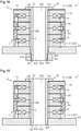
- the motor 1 of a fifth embodiment will now be described with reference to Fig. 18 .
- the motor 1 of the present embodiment differs from the motor 1 of the first embodiment in the structure of the fixing member 60.
- same reference numerals are given to those components having the same functions as the corresponding components of the motor 1 in the first embodiment. Such components will not be described in detail.
- Fig. 18 shows a cross section of the motor 1 without the rotor 50.
- the fixing member 60 includes the first end plate 61, the second end plate 62, and at least one rod-like portion 63. At least one of the first end plate 61 and the second end plate 62 includes a through hole 62E extending in the axial direction and allowing for insertion of the rod-like portion 63. In an example, the second end plate 62 includes the through hole 62E instead of the insertion hole 62B in the first embodiment.
- the fixing member 60 further includes a holding section 65 on which a thread 65A is formed. The thread 65A of the holding section 65 can be joined with the thread 63A of the rod-like portion 63.
- the holding section 65 is arranged to oppose the stator 10 with one of the first end plate 61 and the second end plate 62 located between the holding section 65 and the stator 10.
- the holding section 65 is arranged to oppose the stator 10 via the second end plate 62 located between the holding section 65 and the stator 10.
- the holding section 65 of the present embodiment forms a nut.
- the rod-like portion 63 has a predetermined length in the axial direction.
- the axial length of the rod-like portion 63 is greater than the sum of the thickness of the stator 10 and the thickness of the second end plate 62 in the axial direction.
- the axial length of the rod-like portion 63 is less than or equal to the sum of the thickness of the stator 10, the thickness of the second end plate 62, and the thickness of the holding section 65 in the axial direction.
- the axial length of the rod-like portion 63 in the present embodiment coincides with the sum of the thickness of the stator 10, the thickness of the second end plate 62, and the thickness of holding section 65 in the axial direction.
- the axial length of the rod-like portion 63 may be greater than the sum of the thickness of the stator 10, the thickness of the second end plate 62, and the thickness of the holding section 65 in the axial direction.
- the rod-like portion 63 is fastened to the holding section 65 by inserting the rod-like portion 63 in the through hole 10A of the stator 10 and the through hole 62E of the second end plate 62 and joining the thread 63A of the rod-like portion 63, which projects out of the through hole 62E of the second end plate 62, with the thread 65A of the holding section 65. In this manner, the stator 10 is fixed, sandwiched between the first end plate 61 and the second end plate 62.
- the present embodiment has the following advantages in addition to advantages (1-1) to (1-8) and (1-10) to (1-12) of the first embodiment.
- (5-1) The thread 63A of the rod-like portion 63, which is inserted in the through hole 10A of the stator 10, are inserted through the through hole 62E of the second end plate 62 and joined with the thread 65A of the holding section 65. With this structure, a simple structure fixes the stator 10.
- the motor 1 of a sixth embodiment will now be described with reference to Fig. 19 .
- the motor 1 of the present embodiment differs from the motor 1 of the first embodiment in the structure of the fixing member 60.
- same reference numerals are given to those components having the same functions as the corresponding components of the motor 1 in the first embodiment. Such components will not be described in detail.
- Fig. 19 shows a cross section of the motor 1 without the rotor 50.
- the fixing member 60 includes the first end plate 61, the second end plate 62, and at least one rod-like portion 63. At least one of the first end plate 61 and the second end plate 62 includes a hole 62F extending in the axial direction and allowing for insertion of the rod-like portion 63. In an example, the second end plate 62 includes the hole 62F instead of the insertion hole 62B of the first embodiment. Preferably, the rod-like portion 63 does not include the thread 63A.
- the rod-like portion 63 is fixed to at least one of the first end plate 61 and the second end plate 62 in accordance with, for example, a first example or a second example described as below.
- the rod-like portion 63 is fastened in the hole 62F of at least one of the first end plate 61 and the second end plate 62 through any of press-fitting, shrink-fitting, and expansion-fitting.
- the rod-like portion 63 is fastened in the hole 62F of the second end plate 62 through any of press-fitting, shrink-fitting, and expansion-fitting.
- the rod-like portion 63 is adhered, fused, or welded to at least one of the first end plate 61 and the second end plate 62.
- the rod-like portion 63 is adhered, fused, or welded to the second end plate 62.
- the rod-like portion 63 may be adhered, fused, or welded in the hole 62F of the second end plate 62.
- the second end plate 62 does not have to include the hole 62F.
- the present embodiment has following advantages in addition to advantages (1-1) to (1-8) and (1-10) to (1-12) of the first embodiment.
- the motor 1 of a seventh embodiment will now be described with reference to Fig. 20 .
- the motor 1 of the present embodiment differs from the motor 1 of the first embodiment in the structure of the rod-like portion 63.
- same reference numerals are given to those components having the same functions as the corresponding components of the motor 1 in the first embodiment. Such components will not be described in detail.
- the rod-like portion 63 includes a cavity 63D.
- the rod-like portion 63 includes a through portion 63F extending in the radial direction from an inner circumferential surface 63E, which defines the cavity 63D, to the outer circumferential surface 63B of the rod-like portion 63.
- the through portion 63F is, for example, a slit extending in the axial direction.
- the through portion 63F is large enough to draw out the winding 14 of the stator 10.
- the number of the through portions 63F is two.
- the two through portions 63F are formed in the rod-like portion 63, for example, opposing each other in the radial direction.
- the through portion 63F is formed continuously in the first end plate 61 and the rod-like portion 63.
- the through portion 63F may be formed only in the rod-like portion 63.
- the present embodiment has the following advantages in addition to advantages (1-1) to (1-12) of the first embodiment.
- the rod-like portion 63 includes the through portion 63F extending in the radial direction from the inner circumferential surface 63E, which defines the cavity 63D, to the outer circumferential surface 63B. With this structure, the winding 14 of the stator 10 can be easily drawn out of the through portion 63F. Further, this structure reduces the weight of the motor 1.
- the above embodiments exemplify, without any intention to limit, applicable forms of the motor related to the present disclosure.
- the motor related to the present disclosure can take a form differing from the forms described in the above embodiments.
- some of the components of the embodiments may be replaced, changed, or omitted.
- another component may be added to the embodiments.
- same reference numerals are given to those components that are the same as the corresponding components of the above embodiments. Such components will not be described in detail.
- the structure of the stator iron core 11 may be changed in any manner.
- the distal ends 24A of the first stator claw magnetic poles 22 of the first stator 20 are tapered.
- the distal ends 24A of the first stator claw magnetic poles 22 are tapered in the circumferential direction.
- the same modification can also be applied to the second stator 30.
- the first stator claw magnetic poles 22 of the first stator 20 do not include the second claw magnetic poles 24.
- the second stator claw magnetic poles 32 of the second stator 30 include the first claw magnetic poles 33 and the second claw magnetic poles 34.
- the first stator claw magnetic poles 22 of the first stator 20 further include third claw magnetic poles 25 in addition to the first claw magnetic poles 23 and the second claw magnetic poles 24.
- Each third claw magnetic pole 25 extends from the first claw magnetic pole 23, for example, in the axial direction at the opposite side of the second claw magnetic pole 24.
- the third claw magnetic pole 25 has a shorter axial length than the second claw magnetic pole 24.
- the stator iron cores 11 are formed from an electromagnetic steel sheet.
- the structure of the stator 10 may be changed in any manner.
- the stator 10 is a claw pole type stator having for a number of phases that is two or less or four or greater. In this case, the number of the stator iron cores 11 is two or four or greater.
- the stator 10 does not include the interphase insulation members 40, 80, 90.
- stator 10 of the outer rotor type motor 1 is described.
- the above described structures of the fixing member 60 are also applicable to the rotor 50 of the outer rotor type motor 1.
- stator 10 of the outer rotor type motor 1 is described.
- the above described structures of the fixing member 60 are also applicable to a stator of an inner rotor type motor 1.
- the above described structures of the fixing member 60 are applicable to a rotor 100 of an inner rotor type motor 1.
- An example of the rotor 100 including the structure of the fixing member 60 will now be described.
- the rotor 100 in the inner rotor type motor 1, the rotor 100 may be fixed by the fixing member 60 described in the above embodiments.
- Fig. 24 shows an example of a cross-sectional view of the rotor 100 of the inner rotor type motor.
- the rotor 100 includes a rotor iron core 111 and the fixing member 60 for fixing the rotor iron core 111.
- Magnets (not shown) are arranged on the outer circumference of the rotor iron core 111 in equal intervals in the circumferential direction about the rotation axis RA.
- the rotor iron core 111 is formed by a powder magnetic core.
- the rotor iron core 111 includes a first through hole 111A and second through holes 111B.
- a rotation shaft 160 of the motor 1 is inserted through the first through hole 111A.
- the rod-like portions 64 of the fixing member 60 are inserted through the second through holes 111B.
- the first through hole 111A is formed in the rotor iron core 111 extending along the rotation axis RA.
- the second through holes 111B are arranged in the rotor iron core 111 about the rotation axis RA in intervals in the circumferential direction.
- the fixing member 60 includes the first end plate 61, the second end plate 62, and more than one rod-like portion 64.
- the first end plate 61 includes a first hole 61R through which the rotation shaft 160 is inserted.
- the first end plate 61 is welded or adhered to the rotation shaft 160.
- the second end plate 62 includes a second hole 62R through which the rotation shaft 160 is inserted.
- the second end plate 62 is welded or adhered to the rotation shaft 160.
- the rod-like portions 64 are insertable into the second through holes 111B of the rotor 100.
- the number of the rod-like portions 64 is four.
- the rod-like portions 64 are spaced apart from one another in the circumferential direction.
- the rod-like portions 64 are arranged in equal intervals in the circumferential direction.
- the first end plate 61 is arranged to directly contact one end surface 111D of the rotor 100 in the axial direction.
- the first end plate 61 may be arranged in the rotor 100 with an insulation member located between the first end plate 61 and the end surface 111D in the axial direction.
- the second end plate 62 is arranged to directly contact the other end surface 111E of the rotor 100 in the axial direction.
- the second end plate 62 may be arranged in the rotor 100 with an insulation member located between the second end plate 62 and the other end surface 111E in the axial direction.
- the rod-like portions 64 are fixed to the first end plate 61 and the second end plate 62 in a state in which the rod-like portions 64 are inserted in the second through holes 111B of the rotor 100, and the rotor 100 is sandwiched between the first end plate 61 and the second end plate 62 in the axial direction.
- the first end plate 61, the second end plate 62, and the rod-like portions 64 are formed separately from one another.
- the number of the rod-like portion 64 may be three or less or five or greater.
- each rod-like portion 64 includes a thread 64D.
- the thread 64D is formed on the outer circumferential surface 64B of the rod-like portion 64.
- the thread 64D is formed in the distal end 64C of the rod-like portion 64.
- the thread 64D can be joined with a nut 69.
- the rod-like portion 64 of the present embodiment forms a bolt.
- Each rod-like portion 64 opposes a wall 111C of the second through hole 111B of the rotor 100 with a gap SR extending in between.
- the first end plate 61 includes insertion holes 61B allowing for insertion of the rod-like portions 64.
- the second end plate 62 includes insertion holes 62G allowing for insertion of the rod-like portions 64.
- the first end plate 61, the rod-like portions 64, the second end plate 62, and the rotor iron core 111 are coupled by inserting the rod-like portions 64 through the insertion holes 62G of the second end plate 62 and the second through holes 111B of the rotor 100 into the insertion holes 61B of the first end plate 61, and joining the nuts 69 with the threads 64D of the rod-like portions 64.
- the rotor iron core 111 is fixed to the fixing member 60 by the force compressing the powder magnetic core. This avoids damage to the rotor iron core 111 formed by a powder magnetic core.
- the rotor 100 includes the rotor iron core 111 formed by a powder magnetic core. This structure restricts generation of eddy current and loss that would be caused by an eddy current. Further, this structure increases the degree of freedom for the shape of the rotor iron core 111.
- the claw pole type motor 1 is described in the above embodiments. However, the above described structures of the fixing member 60 are also applicable to a stator and a rotor of the motor 1 that is not claw pole type.
Abstract
Description
- The present disclosure relates to a motor.
-
Patent Document 1 discloses an outer rotor type motor. In the motor, a stator is fixed to a support member. - Patent Document 1:
Japanese Laid-Open Patent Publication No. 2013-158072 - If a stator is formed by a powder magnetic core, when press-fitting a support member to the stator, the press-fitting produces a force acting on the powder magnetic core in the radial direction that may damage the powder magnetic core. Also, if a rotor is formed by a powder magnetic core, when the rotor is press-fitted with respect to an axis, the force of the press-fitting produces a force acting on the powder magnetic core in the radial direction that may damage the powder magnetic core.
- An objective of the present disclosure is to provide a motor that includes an iron core formed by a powder magnetic core and avoids damage to the iron core.
- A motor that solves the above problems includes a stator, a rotor, and a fixing member. The rotor is rotatable relative to the stator. The fixing member includes a first end plate, a second end plate, and at least one rod-like portion. At least one of the stator and the rotor includes an iron core formed by a powder magnetic core. The iron core includes a through hole extending through the iron core in an axial direction of the rotor. The first end plate is arranged to directly or indirectly contact one end surface of the iron core in axial direction. The second end plate is arranged to directly or indirectly contact the other end surface of the iron core in the axial direction. The rod-like portion is fixed to the first end plate and the second end plate in a state in which the rod-like portion is inserted in the through hole of the iron core and the iron core is sandwiched by the first end plate and the second end plate in the axial direction of the rotor.
- With this structure, the rod-like portion, which is inserted in the through hole of the iron core, is fastened to the first end plate and the second end plate so that the iron core is fixed, sandwiched between the first end plate and the second end plate. In this manner, the iron core is fixed to the fixing member by the force compressing the powder magnetic core. This avoids damage to the iron core formed by a powder magnetic core.
- In the motor, it is preferred that one of the first end plate and the second end plate be formed integrally with the rod-like portion.
- The fixing member includes integrally-formed parts that lessen the number of parts of the fixing member.
- In the motor, it is preferred that the rod-like portion include a thread. Further, at least one of the first end plate and the second end plate includes a thread that can be joined with the thread of the rod-like portion.
- The thread of the rod-like portion, which is inserted in the through hole of the iron core, is joined with the thread of at least one of the first end plate and the second end plate. This fixes the iron core with a simple structure.
- In the motor, it is preferred that the fixing member further include a holding section including a thread. The rod-like portion includes a thread. At least one of the first end plate and the second end plate includes a through hole extending through the at least one of the first end plate and the second end plate in the axial direction of the rotor and allowing for insertion of the rod-like portion. The holding section is arranged to oppose the iron core with one of the first end plate and the second end plate located between the holding section and the iron core. The thread of the rod-like portion is joined with the thread of the holding section.
- The thread of the rod-like portion, which is inserted in the through hole of the iron core, is inserted through the through hole of at least one of the first end plate and the second end plate and joined with the thread of the holding section. This fixes the iron core with a simple structure.
- In the motor, it is preferred that at least one of the first end plate and the second end plate include a hole extending in the axial direction of the rotor and allowing for insertion of the rod-like portion. Further, the rod-like portion is fastened in the hole of at least one of the first end plate and the second end plate through any of press-fitting, shrink-fitting, or expansion-fitting.
- The rod-like portion, which is inserted in the through hole of the iron core, is fastened in the hole of at least one of the first end plate and the second end plate through any of press-fitting, shrink-fitting, and expansion-fitting. Thus, the iron core is firmly fixed.
- In the motor, it is preferred that the rod-like portion be adhered, fused, or welded to at least one of the first end plate and the second end plate.
- With this structure, the rod-like portion inserted in the through hole of the iron core is adhered, fused, or welded to at least one of first end plate and the second end plate. Thus, the iron core is firmly fixed.
- In the motor, it is preferred that the rod-like portion oppose a wall of the through hole of the iron core with a gap extending in between in a radial direction of the rotor.
- With this structure, the rod-like portion inserted in the through hole of the iron core does not contact the wall of the through hole. This reduces the force acting on the iron core in the radial direction. Thus, the fixing member stably fixes the iron core.
- In the motor, it is preferred that the fixing member include the rod-like portions. The rod-like portions are spaced apart from one another in a circumferential direction about a rotation axis of the rotor.
- With this structure, the rod-like portions are inserted in the through hole of the iron core and fixed to the first end plate and the second end plate. In this manner, the iron core is firmly fixed.
- In the motor, it is preferred that the rod-like portion include a cavity. Further, the rod-like portion includes a through portion extending in a radial direction of the rotor from an inner circumferential surface that defines the cavity to an outer circumferential surface of the rod-like portion. With this structure, the winding of the iron core can be easily drawn out through the through portion. Further, this structure reduces the weight of the motor.
- In the motor, it is preferred that the stator include a stator iron core formed by a powder magnetic core.
- This structure restricts generation of eddy current and loss that would be caused by an eddy current. Further, this structure increases the degree of freedom for the shape of the stator iron core.
- In the motor, it is preferred that the rotor include a rotor iron core formed by a powder magnetic core.
- This structure restricts generation of eddy current and loss that would be caused by an eddy current. Further, this structure increases the degree of freedom for the shape of the rotor iron core.
- In the motor, it is preferred that the stator include stator iron cores arranged in the axial direction of the rotor and an interphase insulation member arranged between the stator iron cores.
- With this structure, the interphase insulation member is located between the stator iron cores to obtain appropriate insulation between the
stator iron cores 11. This restricts leakage of magnetic flux and improves the performance of the motor. - In the motor, it is preferred that each of the stator iron cores include a circular back yoke and a stator claw magnetic pole. The back yoke includes a through hole. The stator claw magnetic pole projects from the back yoke in a radial direction of the rotor. The interphase insulation member includes a support portion and an insulation portion. The insulation portion is located between adjacent ones of the stator iron cores. The stator claw magnetic pole contacts the support portion in at least one of a circumferential direction about a rotation axis of the rotor and the radial direction of the rotor.
- With this structure, each stator iron core is positioned in at least one of the circumferential direction of the rotor and the radial direction of the rotor by contact of the stator claw magnetic pole with the support portion. In this manner, the stator iron cores can be positioned relative to one another without the need for the stator iron cores to have a complicated structure.
- A referential motor will now be described.
- An outer rotor type motor that includes a claw pole type stator, a rotor, and a fixing member. The rotor is rotatable relative to the claw pole type stator. The fixing member includes a first end plate, a second end plate, and at least one rod-like portion. The claw pole type stator includes a through hole extending through the claw pole type stator in an axial direction of the rotor. The first end plate is arranged to contact an end surface of the claw pole type stator at one end in the axial direction of the rotor. The second end plate is arranged to contact an end surface of the claw pole type stator at the other end in the axial direction of the rotor. The rod-like portion is fixed to the first end plate and the second end plate in a state in which the rod-like portion is inserted in the through hole of the claw pole type stator and the claw pole type stator is sandwiched between the first end plate and the second end plate in the axial direction of the rotor.
- With this structure, the rod-like portion, which is inserted in the through hole of the claw pole type stator, is fastened to the first end plate and the second end plate so that the claw pole type stator is fixed, sandwiched between the first end plate and the second end plate. In this case, subtle force acts on the claw pole type stator in the radial direction of the rotor during manufacturing. Thus, the claw pole type stator can be stably fixed by the fixing member.
- In the motor, it is preferred that one of the first end plate and the second end plate be formed integrally with the rod-like portion.
- The fixing member includes integrally-formed parts that lessen the number of parts of the fixing member.
- In the motor, it is preferred that the rod-like portion include a thread. Further, at least one of the first end plate and the second end plate includes a thread that can be joined with the thread of the rod-like portion.
- The thread of the rod-like portion, which is inserted in the through hole of the claw pole type stator, is joined with the thread of at least one of the first end plate and the second end plate. This fixes the claw pole type stator with a simple structure.
- In the motor, it is preferred that the fixing member further include a holding section including a thread. The rod-like portion includes a thread. At least one of the first end plate and the second end plate includes a through hole extending through the at least one of the first end plate and the second end plate in the axial direction of the rotor and allowing for insertion of the rod-like portion. The holding section is arranged to oppose the claw pole type stator with one of the first end plate and the second end plate located between the holding section and the iron core. The thread of the rod-like portion is joined with the thread of the holding section.
- With this structure, the thread of the rod-like portion, which is inserted in the through hole of the claw pole type stator, is inserted through the through hole of at least one of the first end plate and the second end plate and joined with the thread of the holding section. This fixes the claw pole type stator with a simple structure.
- In the motor, it is preferred that at least one of the first end plate and the second end plate include a hole extending in the axial direction of the rotor and allowing for insertion of the rod-like portion. Further, the rod-like portion is fastened in the hole of the at least one of the first end plate and the second end plate through any of press-fitting, shrink-fitting, or expansion-fitting.
- The rod-like portion, which is inserted in the through hole of the claw pole type stator, is fastened in the hole of at least one of the first end plate and the second end plate through any of press-fitting, shrink-fitting, and expansion-fitting. Thus, the claw pole type stator is firmly fixed.
- In the motor, it is preferred that the rod-like portion be adhered, fused, or welded to at least one of the first end plate and the second end plate.
- With this structure, the rod-like portion inserted in the through hole of the claw pole type stator is adhered, fused, or welded to at least one of first end plate and the second end plate. Thus, the claw pole type stator is firmly fixed.
- In the motor, it is preferred that the rod-like portion oppose a wall of the through hole of the claw pole type stator with a gap extending in between in a radial direction of the rotor.
- With this structure, the rod-like portion inserted in the through hole of the claw pole type stator does not contact the wall of the through hole. This reduces the force acting on the claw pole type stator in the radial direction. Thus, the fixing member stably fixes the claw pole type stator.
- In the motor, it is preferred that the fixing member include the rod-like portions. The rod-like portions are spaced apart from one another in a circumferential direction of the rotor.
- With this structure, the rod-like portions are inserted in the through hole of the claw pole type stator and fixed to the first end plate and the second end plate. Thus, the claw pole type stator is firmly fixed.
- In the motor, it is preferred that the rod-like portion include a cavity. Further, the rod-like portion includes a through portion extending in a radial direction of the rotor from an inner circumferential surface that defines the cavity to an outer circumferential surface of the rod-like portion. With this structure, the winding of the claw pole type stator can be easily drawn out through the through portion. Further, this structure reduces the weight of the motor.
- In the motor, it is preferred that the claw pole type stator include a stator iron core formed by a powder magnetic core.
- This structure restricts generation of eddy current and loss that would be caused by an eddy current. Further, this structure increases the degree of freedom for the shape of the stator iron core.
- In the motor, it is preferred that the claw pole type stator include stator iron cores arranged in the axial direction of the rotor and an interphase insulation member arranged between the stator iron cores.
- With this structure, the interphase insulation member is located between the stator iron cores to obtain appropriate insulation between the
stator iron cores 11. This restricts leakage of magnetic flux and improves the performance of the motor. - In the motor, it is preferred that each of the stator iron cores include a circular back yoke and a stator claw magnetic pole. The back yoke includes a through hole. The stator claw magnetic pole projects from the back yoke in a radial direction of the rotor. The interphase insulation member includes a support portion and an insulation portion. The insulation portion is located between adjacent ones of the stator iron cores. The stator claw magnetic pole contacts the support portion in at least one of the circumferential direction of the rotor and the radial direction of the rotor.
- With this structure, each stator iron core is positioned in at least one of the circumferential direction of the rotor and the radial direction of the rotor by contact of the stator claw magnetic pole with the support portion. In this manner, the stator iron cores can be positioned relative to one another without the need for the stator iron cores to have a complicated structure.
-
-
Fig. 1 is a perspective view of a motor in accordance with a first embodiment. -
Fig. 2 is a perspective view of the motor shown inFig. 1 without a rotor. -
Fig. 3 is an exploded perspective view of the motor shown inFig. 2 . -
Fig. 4 is an exploded perspective view of a stator iron core shown inFig. 3 . -
Fig. 5 is a perspective view of an interphase insulation member shown inFig. 3 . -
Fig. 6 is a perspective view showing the relationship of the inter-phase insulation member shown inFig. 5 and a first stator. -
Fig. 7 is a perspective view showing the relationship of the inter-phase insulation member shown inFig. 5 and a second stator. -
Fig. 8 is a cross-sectional view taken in an axial direction of a rotor. -
Fig. 9 is a perspective view of a motor in accordance with a second embodiment. -
Fig. 10 is a perspective view of an interphase insulation member shown inFig. 9 . -
Fig. 11 is a perspective view showing the relationship of the interphase insulation member shown inFig. 10 and a first stator. -
Fig. 12 is a perspective view showing the relationship of the interphase insulation member shown inFig. 10 and a second stator. -
Fig. 13 is a perspective view of a motor in accordance with a third embodiment. -
Fig. 14 is a perspective view of an interphase insulation member shown inFig. 13 . -
Fig. 15 is a perspective view showing the relationship of the interphase insulation member shown inFig. 14 and a first stator. -
Fig. 16 is a perspective view showing the relationship of the interphase insulation member shown inFig. 14 and a second stator. -
Fig. 17 is a cross-sectional view of a motor taken in an axial direction of a rotor in accordance with a fourth embodiment. -
Fig. 18 is a cross-sectional view of a motor taken in an axial direction of a rotor in accordance with a fifth embodiment. -
Fig. 19 is a cross-sectional view of a motor taken in an axial direction of a rotor in accordance with a sixth embodiment. -
Fig. 20 is a perspective view of a rod-like portion in accordance with a seventh embodiment. -
Fig. 21 is a perspective view showing a first stator of a stator iron core in a modified example. -
Fig. 22 is a perspective view showing a first stator of a stator iron core in another modified example. -
Fig. 23 is a perspective view showing a first stator of a stator iron core in a further modified example. -
Fig. 24 is a cross-sectional view of a rotor iron core in an inner rotor type motor. - A
motor 1 in accordance with a first embodiment will now be described. The scope of the disclosure is defined not by the detailed description, but by the claims and their equivalents, and all variations within the scope of the claims and their equivalents are to be construed as being included in the disclosure. - The
motor 1 includes astator 10, a rotor, and a fixingmember 60. The rotor is rotatable relative to thestator 10. In themotor 1, at least one of thestator 10 and therotor 50 includes an iron core formed by a powder magnetic core. Themotor 1 has the structure of an outer rotor type motor or an inner rotor type motor. - As shown in
Fig. 1 , themotor 1 of the present embodiment is an outer rotor type motor. Themotor 1 is mounted on, for example, an air conditioner (not shown). In an example, themotor 1 is configured to drive a Sirocco fan (not shown) installed in the air conditioner. Themotor 1 includes therotor 50, which is rotatable relative to the claw-pole type stator 10 (hereafter, "thestator 10"), and the fixingmember 60 that allows for fixing of thestator 10. - The
rotor 50 has a rotation axis RA. Therotor 50 is rotatable about the rotation axis RA. Therotor 50 includesrotor iron cores 51 andmagnets 52. Therotor iron cores 51 are arranged in an axial direction of the rotation axis RA. Themagnets 52 are arranged on an innercircumferential surface 51A of eachrotor iron core 51. The axial direction of the rotation axis RA coincides with the axial direction of the rotor 50 (hereafter, "the axial direction"). Therotor iron cores 51 are, for example, annular. The number of therotor iron cores 51 corresponds to the number ofstator iron cores 11 of the stator 10 (refer toFig. 2 ). In an example, the number of therotor iron cores 51 is three. Themagnets 52 are arranged, for example, on the innercircumferential surface 51A of eachrotor iron core 51 in a circumferential direction about the rotation axis RA and oppose an outercircumferential surface 11D of a corresponding one of the stator iron cores 11 (refer toFig. 2 ). In an example, twentymagnets 52 are arranged on the innercircumferential surfaces 51A of therotor iron cores 51 in the circumferential direction about the rotation axis RA. The circumferential direction about the rotation axis RA coincides with the circumferential direction of the rotor 50 (hereafter, "the circumferential direction"). Themagnets 52 are, for example, permanent magnets. - As shown in
Fig. 2 , thestator 10 includes thestator iron cores 11 arranged in the axial direction andinterphase insulation members 40 arranged between thestator iron cores 11. Eachstator iron core 11 is formed by a powder magnetic core. The number of thestator iron cores 11 is two or greater. In an example, the number of thestator iron cores 11 is three. Thestator 10 in the present embodiment has a three-dimensional magnetic structure and is a three-phase claw pole type stator, in which thestator iron cores 11 are arranged in the order of U-phase, V-phase, and W-phase. In the example shown inFig. 2 , thestator iron cores 11 of different phases are arranged together and positioned in the circumferential direction so that the phases of thestator iron cores 11 differ from one another by 120° in electrical angle. - Each
interphase insulation member 40 is a non-magnetic body. In an example, theinterphase insulation member 40 is formed from resin. Theinterphase insulation member 40 is arranged between onestator iron core 11 and anotherstator iron core 11 that are located next to each other in the axial direction so that the onestator iron core 11 is insulated from the otherstator iron core 11. The number of theinterphase insulation members 40 is determined by the number of thestator iron cores 11. In an example, the number of theinterphase insulation member 40 is two. InFig. 2 , theinterphase insulation members 40 are dotted. - As shown in
Fig. 3 , thestator 10 further includes aninsulator 70 located between the fixingmember 60 and thestator iron cores 11. Theinsulator 70 is a non-magnetic body. In an example, theinsulator 70 is formed from resin. Theinsulator 70 is arranged between the fixingmember 60 and thestator iron cores 11 so that the fixingmember 60 is insulated from thestator iron cores 11. In the axial direction, theinsulator 70 is arranged in at least one of two positions, one between thestator iron cores 11 and afirst end plate 61 of the fixingmember 60 and the other between thestator iron cores 11 and asecond end plate 62 of the fixingmember 60. In the example shown inFig. 3 , theinsulator 70 is located between thestator iron cores 11 and thefirst end plate 61 of the fixingmember 60. - The
insulator 70 has a form of, for example, one-half of aninterphase insulation member 40 obtained by equally dividing theinterphase insulation member 40 into two along a plane orthogonal to the axial direction. In this case, anend surface 71 of theinsulator 70 that opposes thefirst end plate 61 of the fixingmember 60 is flat. Theend surface 71 of theinsulator 70 forms oneend surface 10B of thestator 10. Theinsulator 70 may have substantially the same shape as theinterphase insulation member 40. Alternatively, theinsulator 70 may have the form of a flat plate. The form obtained by equally dividing theinterphase insulation member 40 into two along a plane orthogonal to the axial direction may be provided on the portion of thesecond end plate 62 opposing thestator iron core 11. Theinsulator 70 may be omitted from thestator 10. In this example, anend surface 11B of the U-phasestator iron core 11 that opposes thefirst end plate 61 of the fixingmember 60 defines theend surface 10B of thestator 10. - The
stator 10 includes a throughhole 10A extending in the axial direction. In an example, eachstator iron core 11 includes a throughhole 11A extending in the axial direction, eachinterphase insulation member 40 includes a throughhole 40A extending in the axial direction, and theinsulator 70 includes a through hole 70A extending in the axial direction. The throughholes 11A of thestator iron cores 11, the throughholes 40A of theinterphase insulation members 40, and the through hole 70A of theinsulator 70 define the throughhole 10A of thestator 10. The throughholes 11A of thestator iron cores 11, the throughholes 40A of theinterphase insulation members 40, and the through hole 70A of theinsulator 70 have substantially the same size. - The fixing
member 60 includes thefirst end plate 61, thesecond end plate 62, and at least one rod-like portion 63. Thefirst end plate 61 has the form of, for example, a disc. Thefirst end plate 61 is arranged to contact oneend surface 10B of thestator 10 in the axial direction. In an example, thefirst end plate 61 is arranged to contact theend surface 71 of theinsulator 70. In the example in which theinsulator 70 is omitted from thestator 10, thefirst end plate 61 is arranged to contact theend surface 11B of the U-phasestator iron core 11. Thesecond end plate 62 has the form of, for example, a disc. In an example, thesecond end plate 62 has the form of a disc having a larger diameter than thefirst end plate 61. Thesecond end plate 62 is arranged to contact theother end surface 10C of thestator 10 in the axial direction (refer toFig. 8 ). Theend surface 10C of thestator 10 is formed by anend surface 11C of the W-phase stator iron core 11 (refer toFig. 8 ). In an example, thesecond end plate 62 is arranged to contact theend surface 11C of the W-phasestator iron core 11. - The rod-
like portion 63 is insertable into the throughhole 10A of thestator 10. The rod-like portion 63 is fixed to thefirst end plate 61 and thesecond end plate 62 in a state in which the rod-like portion 63 is inserted in the throughhole 10A of thestator 10 and thestator 10 is sandwiched by thefirst end plate 61 and thesecond end plate 62 in the axial direction. One of thefirst end plate 61 and thesecond end plate 62 is formed integrally with the rod-like portion 63. The rod-like portion 63 in the present embodiment is formed integrally with thefirst end plate 61. The rod-like portion 63 may be formed integrally with thesecond end plate 62. - The rod-
like portion 63 includes athread 63A. Thethread 63A is formed in an outercircumferential surface 63B of the rod-like portion 63. In an example, thethread 63A is formed in adistal end 63C of the rod-like portion 63. At least one of thefirst end plate 61 and thesecond end plate 62 includes athread 62A that can be joined with thethread 63A of the rod-like portion 63. Thesecond end plate 62 includes aninsertion hole 62B allowing for insertion of the rod-like portion 63. Theinsertion hole 62B extends through thesecond end plate 62 in, for example, the axial direction. Theinsertion hole 62B does not have to extend through thesecond end plate 62 in the axial direction. Thethread 62A is formed in the wall of theinsertion hole 62B of thesecond end plate 62. When the fixingmember 60 includes more than one rod-like portion 63, thefirst end plate 61 and thesecond end plate 62 may both include thethread 62A. The rod-like portion 63 is fastened to thesecond end plate 62 by inserting the rod-like portion 63 through the throughhole 10A of thestator 10 and into theinsertion hole 62B of thesecond end plate 62 and then joining thethread 63A of the rod-like portion 63 with thethread 62A of thesecond end plate 62. In this manner, thestator 10 is fixed, sandwiched between thefirst end plate 61 and the second end plate 62 (refer toFig. 8 ). - The structure of each
stator iron core 11 will now be described with reference toFig. 4 . - The
stator iron core 11 includes acircular back yoke 12 and stator clawmagnetic poles 13 projecting from theback yoke 12 in a radial direction of the rotor 50 (hereafter, "the radial direction"). Theback yoke 12 in the present embodiment is annular. The throughhole 11A of thestator iron core 11 is formed in theback yoke 12. That is, theback yoke 12 includes the throughhole 11A. The stator clawmagnetic poles 13 project from an outercircumferential surface 12A of theback yoke 12 in the radial direction and extend in the axial direction. - The
stator iron core 11 includes afirst stator 20 and asecond stator 30. Thefirst stator 20 includes a circularfirst back yoke 21 and first stator clawmagnetic poles 22 projecting from thefirst back yoke 21 in the radial direction. Thefirst back yoke 21 in the present embodiment is annular. Thefirst back yoke 21 forms theback yoke 12. The first stator clawmagnetic poles 22 project from thefirst back yoke 21 in the radial direction and extend at least toward thesecond stator 30 in the axial direction. In an example, the first stator clawmagnetic poles 22 project from an outercircumferential surface 21A of thefirst back yoke 21 and extend toward thesecond stator 30 in the axial direction. The first stator clawmagnetic poles 22 form the stator clawmagnetic poles 13. In an example, the number of the first stator clawmagnetic poles 22 is ten. The first stator clawmagnetic poles 22 are arranged, for example, on the outercircumferential surface 21A of thefirst back yoke 21 in equal intervals in the circumferential direction. - Each of the first stator claw
magnetic poles 22 includes a first clawmagnetic pole 23 and a second clawmagnetic pole 24. The first clawmagnetic pole 23 is formed by a portion including the base of the first stator clawmagnetic pole 22. The first clawmagnetic pole 23 extends from the outercircumferential surface 21A of thefirst back yoke 21 in the radial direction. The second clawmagnetic pole 24 is formed by a portion including adistal end 24A of the first stator clawmagnetic pole 22. The second clawmagnetic pole 24 extends from the first clawmagnetic pole 23 toward thesecond stator 30. The second clawmagnetic pole 24 is, for example, box-shaped. In an example, anouter surface 24B of the second clawmagnetic pole 24, which forms the outercircumferential surface 11D of thestator iron core 11, opposes themagnets 52 of therotor 50. - The
second stator 30 has, for example, substantially the same structure as thefirst stator 20. Thesecond stator 30 includes a circularsecond back yoke 31 and second stator clawmagnetic poles 32 projecting from thesecond back yoke 31 in the radial direction. Thesecond back yoke 31 in the present embodiment is annular. Thesecond back yoke 31 forms theback yoke 12. The second stator clawmagnetic poles 32 project from thesecond back yoke 31 in the radial direction and extend at least toward thefirst stator 20 in the axial direction to form gaps G between the second stator clawmagnetic poles 32 and the first stator clawmagnetic poles 22 in the circumferential direction (refer toFig. 3 ). In an example, the second stator clawmagnetic poles 32 project from an outercircumferential surface 31A of thesecond back yoke 31 in the radial direction and extend toward thefirst stator 20 in the axial direction. The second stator clawmagnetic poles 32 form the stator clawmagnetic poles 13. In an example, the number of the second stator clawmagnetic poles 32 is ten. The second stator clawmagnetic poles 32 are arranged, for example, on the outercircumferential surface 31A of thesecond back yoke 31 in equal intervals in the circumferential direction. - Each of the second stator claw
magnetic poles 32 includes a first clawmagnetic pole 33 and a second clawmagnetic pole 34. The first clawmagnetic pole 33 is formed by a portion including the base of the second stator clawmagnetic pole 32. The first clawmagnetic pole 33 extends from the outercircumferential surface 31A of thesecond back yoke 31 in the radial direction. The second clawmagnetic pole 34 is formed by a portion including adistal end 34A the second stator clawmagnetic pole 32. The second clawmagnetic poles 34 extend from the first clawmagnetic poles 33 toward thefirst stator 20 to form the gaps G between the second clawmagnetic poles 34 and the second clawmagnetic poles 24 of the first stator clawmagnetic pole 22 in the circumferential direction. The second clawmagnetic pole 34 is, for example, box-shaped. In an example, anouter surface 34B of the second clawmagnetic pole 34, which forms the outercircumferential surface 11D of thestator iron core 11, opposes themagnets 52 of therotor 50. - The
stator 10 further includes an annular winding 14. The winding 14 is connected to, for example, an inverter circuit-current conversion circuit (not shown) or the like. The winding 14 is arranged between thefirst stator 20 and thesecond stator 30 in the axial direction. In an example, thestator iron core 11 is formed by arranging the winding 14 between thefirst stator 20 and thesecond stator 30 and coupling thefirst stator 20 with thesecond stator 30 such that the gaps G are formed between the first stator clawmagnetic poles 22 and the second stator clawmagnetic poles 32 in the circumferential direction. In the present embodiment, theinterphase insulation member 40 determines the positional relationship of thefirst stator 20 and thesecond stator 30, and the fixingmember 60 couples thefirst stator 20 and thesecond stator 30. - The structure of each
interphase insulation member 40 will now be described with reference toFigs. 5 to 7 . - As shown in
Fig. 5 , theinterphase insulation member 40 includes aninsulation portion 41 andsupport portions 42. Theinsulation portion 41 is arranged between adjacentstator iron cores 11. Theinsulation portion 41 is, for example, annular. Theinsulation portion 41 is sheet-like, hollow, or meshed. Theinsulation portion 41 in the present embodiment is sheet-like. Thesupport portions 42 are arranged on theinsulation portion 41 to contact the stator clawmagnetic poles 13 of thestator iron cores 11. In an example, thesupport portions 42 are arranged on theinsulation portion 41 to extend in at least one of the axial direction and the radial direction. The stator clawmagnetic poles 13 contact thesupport portions 42 in at least one of the circumferential direction and the radial direction. In the present embodiment, the stator clawmagnetic poles 13 contact thesupport portions 42 in the circumferential direction (refer toFig. 2 ). Specifically, thesupport portions 42 contact the first stator clawmagnetic poles 22 and the second stator clawmagnetic poles 32 of thestator iron cores 11, which are adjacent to theinsulation portion 41, in the circumferential direction. - The
support portions 42 includefirst support portions 43 andsecond support portions 44. Thefirst support portions 43 extend from afirst surface 41A of theinsulation portion 41 in the axial direction. Thesecond support portions 44 extend from asecond surface 41C of theinsulation portion 41 in the axial direction at the opposite side of thefirst surface 41A. Thefirst support portions 43 are arranged at positions that differ from where thesecond support portions 44 are arranged in the circumferential direction. The difference in circumferential position between thefirst support portions 43 and thesecond support portions 44 is set based on the position of thestator iron core 11 for each phase in the circumferential direction. Thestator iron core 11 contacting thefirst support portions 43 is located next to thestator iron core 11 contacting thesecond support portions 44 in the axial direction. - The
first support portions 43 are arranged on anedge 41B of thefirst surface 41A of theinsulation portion 41. In an example, the number of thefirst support portions 43 is twenty. Thefirst support portions 43 are arranged, for example, on theedge 41B of thefirst surface 41A of theinsulation portion 41 in equal intervals in the circumferential direction. Eachfirst support portion 43 is post-shaped. In an example, thefirst support portion 43 has the form of a substantially quadrilateral post that becomes smaller toward the rotation axis RA of therotor 50 in the radial direction. - As shown in
Fig. 6 , the first side surfaces 43A of thefirst support portions 43 contact the first stator clawmagnetic poles 22 of thefirst stator 20 in the circumferential direction. In an example, each first stator clawmagnetic pole 22 is sandwiched between the first side surfaces 43A of opposingfirst support portions 43 in the circumferential direction. In this manner, thefirst stator 20 is positioned in the circumferential direction by contact of the first stator clawmagnetic poles 22 with the first side surfaces 43A of thefirst support portions 43. - Each
first support portion 43 includes aside surface 43C (hereafter, "thethird side surface 43C") that is located toward the rotation axis RA in the radial direction and contacts thefirst back yoke 21 of thefirst stator 20. In an example, the third side surfaces 43C of thefirst support portions 43 contact the outercircumferential surface 21A of thefirst back yoke 21 in the radial direction. In this manner, thefirst stator 20 is positioned in the radial direction by contact of thefirst back yoke 21 with the third side surfaces 43C of thefirst support portions 43 in the radial direction. - As shown in
Fig. 7 , the second side surfaces 43B of thefirst support portions 43 contact the second stator clawmagnetic poles 32 of thesecond stator 30 in the circumferential direction. Specifically, the second side surfaces 43B of thefirst support portions 43 contact the distal ends 34A of the second stator clawmagnetic poles 32 in the circumferential direction. In the example shown inFig. 7 , thesecond side surface 43B of eachfirst support portion 43 contacts aside surface 34C of the corresponding second clawmagnetic pole 34 that includes thedistal end 34A of the second stator clawmagnetic pole 32. In an example, eachdistal end 34A of the second stator clawmagnetic pole 32 is sandwiched between the second side surfaces 43B of opposingfirst support portions 43 in the circumferential direction. In this manner, thesecond stator 30 is positioned in the circumferential direction by contact of the second stator clawmagnetic poles 32 with the second side surfaces 43B of thefirst support portions 43. - The
second support portions 44 are arranged on anedge 41D of thesecond surface 41C of theinsulation portion 41. In an example, the number of thesecond support portions 44 is twenty. Thesecond support portions 44 are arranged, for example, on theedge 41D of thesecond surface 41C of theinsulation portion 41 in equal intervals in the circumferential direction. Thesecond support portions 44 have substantially the same structure as thefirst support portions 43. - One
side surface 44A (hereafter, "thefirst side surface 44A") of eachsecond support portion 44 contacts one of the corresponding stator clawmagnetic pole 22 of thefirst stator 20 and the corresponding stator clawmagnetic pole 23 of thesecond stator 30 in the circumferential direction. Theother side surface 44B (hereafter, "thesecond side surface 44B") of eachsecond support portion 44 contacts the other one of the corresponding stator clawmagnetic pole 22 of thefirst stator 20 and the corresponding stator clawmagnetic pole 23 of thesecond stator 30 in the circumferential direction. The positional relationship of the side surfaces 44A and 44B of eachsecond support portion 44 is reversed in the one of thesecond support portions 44 adjacent in the circumferential direction. In other words, in adjacent ones of thesecond support portions 44 in the circumferential direction, the first side surfaces 44A oppose each other or the second side surfaces 44B oppose each other. - The first side surfaces 44A of the
second support portions 44 contact the second stator clawmagnetic poles 32 of thesecond stator 30 in the circumferential direction. The relationship of the first side surfaces 44A of thesecond support portions 44 and the second stator clawmagnetic poles 32 is substantially the same as the relationship of the first side surfaces 43A of thefirst support portions 43 and the first stator clawmagnetic poles 22. Thus, thesecond stator 30 is positioned in the circumferential direction by contact of the second stator clawmagnetic poles 32 with the first side surfaces 44A of thesecond support portions 44. - Each
second support portion 44 includes a side surface (hereafter, "the third side surface") that is located toward the rotation axis RA in the radial direction and contacts thesecond back yoke 31 of thesecond stator 30. The relationship of the third side surfaces of thesecond support portions 44 and thesecond back yoke 31 is substantially the same as the relationship of the third side surfaces 43C of thefirst support portions 43 and thefirst back yoke 21. Thus, thesecond stator 30 is positioned in the radial direction by contact of thesecond back yoke 31 with the third side surfaces of thesecond support portions 44. - The second side surfaces 44B of the
second support portions 44 contact the first stator clawmagnetic poles 22 of thefirst stator 20 in the circumferential direction. The relationship of the second side surfaces 44B of thesecond support portions 44 and the first stator clawmagnetic poles 22 is substantially the same as the relationship of the second side surfaces 43B of thefirst support portions 43 and the second stator clawmagnetic poles 32. Thus, thefirst stator 20 is positioned in the circumferential direction by contact of the first stator clawmagnetic poles 22 with the second side surfaces 44B of thesecond support portions 44. In this manner, in the twostator iron cores 11 located next to each other in the axial direction, onestator iron core 11 is positioned by thefirst support portions 43 and the otherstator iron core 11 is positioned by thesecond support portions 44. - The
insulation portion 41 of theinterphase insulation member 40 axially contacts one of the distal ends 24A of the first stator clawmagnetic poles 22 and the distal ends 34A of the second stator clawmagnetic poles 32 of thestator iron cores 11, which are adjacent to theinsulation portion 41, that extend toward theinsulation portion 41. In an example, thefirst surface 41A of theinsulation portion 41 contacts the distal ends 34A of the second stator clawmagnetic poles 32 in the axial direction, and thesecond surface 41C of theinsulation portion 41 contacts the distal ends 24A of the first stator clawmagnetic poles 22 on in the axial direction. Theinsulation portion 41 does not have to axially contact one of the distal ends 24A of the first stator clawmagnetic poles 22 and the distal ends 34A of the second stator clawmagnetic poles 32 of thestator iron cores 11, which are adjacent to theinsulation portion 41, that extend toward theinsulation portion 41. - As shown in
Fig. 8 , the rod-like portion 63 has a predetermined length in the axial direction. The axial length of the rod-like portion 63 is greater than the thickness of thestator 10 in the axial direction. Preferably, the axial length of the rod-like portion 63 is less than or equal to the sum of the thickness of thestator 10 and the thickness of thesecond end plate 62 in the axial direction. The axial length of the rod-like portion 63 in the present embodiment coincides with the sum of the thickness of thestator 10 and the thickness of thesecond end plate 62 in the axial direction. The axial length of the rod-like portion 63 may be greater than the sum of the thickness of thestator 10 and the thickness of thesecond end plate 62 in the axial direction. - The outer diameter of the rod-
like portion 63 is smaller than the diameter of the throughhole 10A of thestator 10. In an example, the rod-like portion 63 opposes awall 10D of the throughhole 10A of thestator 10 with a gap S extending in between in the radial direction. The gap S is greater than or equal to space that would be provided for a fitting tolerance of the rod-like portion 63 in the throughhole 10A of thestator 10. In an example, the gap S is large enough to draw out the winding 14. - The
stator 10 is formed by combining thestator iron cores 11 of each phase, theinterphase insulation members 40, and theinsulator 70 so that thestator iron cores 11 of each phase are positioned by theinterphase insulation members 40 and theinsulator 70. Then, the rod-like portion 63 is inserted in the throughhole 10A of thestator 10, and thethread 63A of the rod-like portion 63 is joined with thethread 62A of thesecond end plate 62 to form themotor 1. In themotor 1, thestator 10 is be fixed by the fixingmember 60 in a state in which thestator iron cores 11 are positioned relative to one another. - The present embodiment has the following advantages.
- (1-1) In the
stator 10, the stator clawmagnetic poles 13 contact thesupport portions 42 in the circumferential direction. With this structure, thestator iron cores 11 are positioned in the circumferential direction by contact of the stator clawmagnetic poles 13 with thesupport portions 42. This positions thestator iron cores 11 relative to one another without the need for thestator iron cores 11 to have a complicated structure. - (1-2) The
first support portions 43 are arranged at positions that differ from where thesecond support portions 44 are arranged in the circumferential direction. With this structure, one of thestator iron cores 11 adjacent to theinterphase insulation member 40 is positioned by contact of the stator clawmagnetic poles 13 with thefirst support portions 43, and the other one of thestator iron cores 11 adjacent to theinterphase insulation member 40 is positioned by contact of the stator clawmagnetic poles 13 with thesecond support portions 44. Thus, thestator iron cores 11 can be positioned in a state in which thestator iron cores 11 are located at different positions in the circumferential direction. - (1-3) Each
stator iron core 11 is formed so that the first stator clawmagnetic poles 22 and the second stator clawmagnetic poles 32 are alternately arranged in the circumferential direction. This structure enlarges the area of thestator iron cores 11 opposing therotor 50 and generates stable torque. - (1-4) The
support portions 42 contact the first stator clawmagnetic poles 22 and the second stator clawmagnetic poles 32 of thestator iron cores 11, which are adjacent to theinsulation portion 41, in the circumferential direction. With this structure, in thestator iron cores 11 adjacent to theinsulation portion 41, thefirst stators 20 are positioned in the circumferential direction by contact of the first stator clawmagnetic poles 22 with thesupport portions 42, and thesecond stators 30 are positioned in the circumferential direction by contact of the second stator clawmagnetic poles 32 with thesupport portions 42. This positions thestator iron cores 11 in the circumferential direction. Further, thefirst stators 20 and thesecond stators 30 can be positioned in the circumferential direction without the need for thestator iron cores 11 to have a complicated structure. - (1-5) In the
insulation portion 41, thefirst surface 41A contacts the distal ends 34A of the second stator clawmagnetic poles 32 in the axial direction, and thesecond surface 41C contacts the distal ends 24A of the first stator clawmagnetic poles 22 in the axial direction. With this structure, thefirst surface 41A of theinsulation portion 41 supports the distal ends 34A of the second stator clawmagnetic poles 32, and thesecond surface 41C of theinsulation portion 41 supports the distal ends 24A of the first stator clawmagnetic poles 22. This reinforces the stator clawmagnetic poles stator iron cores 11. - (1-6) The rod-
like portion 63 is fixed to thefirst end plate 61 and thesecond end plate 62 in a state in which the rod-like portion 63 is inserted in the throughhole 10A of thestator 10 and thestator 10 is sandwiched between thefirst end plate 61 and thesecond end plate 62 in the axial direction. With this structure, the rod-like portion 63, which is inserted in the throughhole 10A of thestator 10, is fixed to thefirst end plate 61 and thesecond end plate 62. Thus, thestator 10 is fixed, sandwiched between thefirst end plate 61 and thesecond end plate 62. In this case, subtle force acts on thestator 10 in the radial direction during manufacturing. Thus, thestator 10 can be stably fixed by the fixingmember 60. - (1-7) Preferably, the
stator 10 includes thestator iron cores 11 each formed by a powder magnetic core. The rod-like portion 63 is fixed to thefirst end plate 61 and thesecond end plate 62 in a state in which the rod-like portion 63 is inserted in the throughhole 10A of thestator 10 and thestator 10 is sandwiched between thefirst end plate 61 and thesecond end plate 62 in the axial direction. With this structure, the rod-like portion 63, which is inserted in the throughholes 10A of thestator iron cores 11, is fixed to thefirst end plate 61 and thesecond end plate 62 so that thestator iron cores 11 are fixed, sandwiched between thefirst end plate 61 and thesecond end plate 62. Thus, thestator iron cores 11 are fixed to the fixingmember 60 by the force compressing the powder magnetic cores. This avoids damage to thestator iron cores 11, which are formed by powder magnetic cores. - (1-8) The rod-
like portion 63 is formed integrally with thefirst end plate 61. Thus, the fixingmember 60 includes integrally-formed parts that lessen the number of parts of the fixingmember 60. - (1-9) The rod-
like portion 63 is inserted in the throughhole 10A of thestator 10 to join thethread 63A of the rod-like portion 63 with thethread 62A of thesecond end plate 62. This fixes thestator 10 with a simple structure. - (1-10) The rod-
like portion 63 opposes thewall 10D of the throughhole 10A of thestator iron core 11 of thestator 10 with the gap S extending in between in the radial direction. With this structure, the rod-like portion 63 inserted in the throughhole 10A of thestator 10 does not contact thewall 10D of the throughhole 10A. This reduces the force acting on thestator 10 in the radial direction. Thus, the fixingmember 60 stably fixes thestator 10. - (1-11) The
stator iron cores 11 are formed by powder magnetic cores. This structure restricts the generation of eddy current and limits loss that would be caused by an eddy current. Further, the degree of freedom for the shape of thestator iron cores 11 is increased. - (1-12) The
stator 10 includes thestator iron cores 11 arranged in the axial direction of therotor 50 and theinterphase insulation members 40 arranged between thestator iron cores 11. With this structure, eachinterphase insulation member 40 arranged between thestator iron cores 11 provides appropriate insulation between thestator iron cores 11. This restricts leakage of magnetic flux and improves the performance of themotor 1. - The
motor 1 of a second embodiment will now be described with reference toFigs. 9 to 12 . Themotor 1 of the present embodiment differs from themotor 1 of the first embodiment in the structure of the interphase insulation member. In the description hereafter, same reference numerals are given to those components having the same functions as the corresponding components of themotor 1 in the first embodiment. Such components will not be described in detail.Fig. 9 shows themotor 1 without therotor 50. - As shown in
Fig. 9 , thestator 10 includes thestator iron cores 11 arranged in the axial direction and aninterphase insulation member 80 arranged between thestator iron cores 11. Theinterphase insulation member 80 is a non-magnetic body. In an example, theinterphase insulation member 80 is formed from resin. Theinterphase insulation member 80 is arranged between onestator iron core 11 and anotherstator iron core 11 that are located next to each other in the axial direction so that the onestator iron core 11 is insulated from the otherstator iron core 11. The number of theinterphase insulation members 80 is determined by the number of thestator iron cores 11. In an example, the number of theinterphase insulation members 80 is two. InFig. 9 , theinterphase insulation members 80 are dotted. Theinsulator 70 in the present embodiment may have the form obtained by equally dividing theinterphase insulation member 80 into two along a plane orthogonal to the axial direction. Alternatively, theinsulator 70 may have the form of a flat plate or substantially the same shape as theinterphase insulation member 80. - As shown in
Fig. 10 , eachinterphase insulation member 80 includes a throughhole 80A extending in the axial direction. The throughhole 80A defines the throughhole 10A of thestator 10. Theinterphase insulation member 80 includes aninsulation portion 81 andsupport portions 82. Theinsulation portion 81 is arranged between adjacentstator iron cores 11. Theinsulation portion 81 has substantially the same shape as theinsulation portion 41 of the first embodiment. Thesupport portions 82 are arranged on theinsulation portion 81 to contact the stator clawmagnetic poles 13 of thestator iron cores 11. In an example, thesupport portions 82 are arranged on theinsulation portion 81 to extend in at least one of the axial direction and the radial direction. The stator clawmagnetic poles 13 contact thesupport portions 82 in at least one of the circumferential direction and the radial direction. In the present embodiment, the stator clawmagnetic poles 13 contact thesupport portions 82 in the circumferential direction and the radial direction (refer toFig. 9 ). Specifically, thesupport portions 82 contact one of the first stator clawmagnetic poles 22 and the second stator clawmagnetic poles 32 of thestator iron cores 11, which are adjacent to theinsulation portion 81, in the circumferential direction and contact the other one of the first stator clawmagnetic poles 22 and the second stator clawmagnetic poles 32 in the radial direction. - The
support portions 82 includefirst support portions 83 andsecond support portions 84. Thefirst support portions 83 extend from afirst surface 81A of theinsulation portion 81 in the axial direction. Thesecond support portions 84 extend from asecond surface 81C of theinsulation portion 81 in the axial direction at the opposite side of thefirst surface 81A. Thefirst support portions 83 are arranged at positions differing from where thesecond support portions 84 are arranged in the circumferential direction. The difference in position between thefirst support portions 83 and thesecond support portions 84 in the circumferential direction is set based on the positions of thestator iron cores 11 of each phase in the circumferential direction. Thestator iron core 11 contacting thefirst support portions 83 is located next to thestator iron core 11 contacting thesecond support portions 84 in the axial direction. - The
first support portions 83 are arranged near anedge 81B of thefirst surface 81A of theinsulation portion 81. In an example, thefirst support portions 83 are arranged on thefirst surface 81A so that a predetermined gap extends between thefirst support portions 83 and theedge 81B of thefirst surface 81A in the radial direction. The predetermined gap is large enough to accommodate the distal ends 24A and 34A of the stator clawmagnetic poles first support portions 83 is ten. Thefirst support portions 83 are arranged, for example, near theedge 81B of thefirst surface 81A of theinsulation portion 81 in equal intervals in the circumferential direction. Thefirst support portions 83 extend in the circumferential direction. Eachfirst support portion 83 is post-shaped. In an example, thefirst support portion 83 has the form of a substantially quadrilateral post that becomes smaller toward the rotation axis RA of therotor 50 in the radial direction. - Each
first support portion 83 includes aside surface 83A (hereafter, "thefirst side surface 83A") that contacts one of a corresponding one of the stator clawmagnetic poles 22 of thefirst stator 20 and a corresponding one of the stator clawmagnetic poles 23 of thesecond stator 30 in the circumferential direction. Eachfirst support portion 83 includes aside surface 83B (hereafter, "thesecond side surface 83B") at a side opposite to aside surface 83C that is located toward the rotation axis RA in the radial direction. Thesecond side surface 83B contacts the other one of a corresponding one of the stator clawmagnetic poles 22 of thefirst stator 20 and a corresponding one of the stator clawmagnetic poles 23 of thesecond stator 30 - As shown in
Fig. 11 , the first side surfaces 83A of thefirst support portions 83 contact the first stator clawmagnetic poles 22 of thefirst stator 20 in the circumferential direction. Specifically, the first side surfaces 83A of thefirst support portions 83 contact the first clawmagnetic poles 23 of the first stator clawmagnetic poles 22 in the circumferential direction. In an example, the first clawmagnetic poles 23 of the first stator clawmagnetic poles 22 are each sandwiched by the opposing first side surfaces 83A of thefirst support portions 83 in the circumferential direction. Thus, thefirst stator 20 is positioned in the circumferential direction by contact of the first stator clawmagnetic poles 22 with the first side surfaces 83A of thefirst support portions 83. - In each
first support portion 83, theside surface 83C (hereafter, "thethird side surface 83C") that is located toward the rotation axis RA in the radial direction contacts thefirst back yoke 21 of thefirst stator 20. In an example, the third side surfaces 83C of thefirst support portions 83 contact the outercircumferential surface 21A of thefirst back yoke 21 in the radial direction. In this manner, thefirst stator 20 is positioned in the radial direction by contact of thefirst back yoke 21 with the third side surfaces 83C of thefirst support portions 83. - As shown in
Fig. 12 , the second side surfaces 83B of thefirst support portions 83 contact the second stator clawmagnetic poles 32 of thesecond stator 30 in the radial direction. Specifically, the second side surfaces 83B of thefirst support portions 83 contact the distal ends 34A of the second stator clawmagnetic poles 32 in the radial direction. In the example shown inFig. 12 , thesecond side surface 83B of eachfirst support portion 83 contacts aninner surface 34D of the second clawmagnetic pole 34 that includes thedistal end 34A of the second stator clawmagnetic pole 32. Theinner surface 34D of the second clawmagnetic pole 34 faces the rotation axis RA in the radial direction. In an example, the distal ends 34A of the second stator clawmagnetic poles 32 are arranged in the predetermined gap and contact the second side surfaces 83B of thefirst support portions 83. Thus, thesecond stator 30 is positioned in the radial direction by contact of the second stator clawmagnetic poles 32 with the second side surfaces 83B of thefirst support portions 83. - The
second support portions 84 are arranged near anedge 81D of thesecond surface 81C of theinsulation portion 81. In an example, thesecond support portions 84 are arranged on thesecond surface 81C so that a predetermined gap is formed between thesecond support portions 84 and theedge 81D of thesecond surface 81C in the radial direction. In an example, the number of thesecond support portions 84 is ten. Thesecond support portions 84 are arranged, for example, near theedge 81D of thesecond surface 81C of theinsulation portion 81 in equal intervals in the circumferential direction. Thesecond support portions 84 have substantially the same structure as thefirst support portions 83. - Each
second support portion 84 includes aside surface 84A (hereafter, "thefirst side surface 84A") that contacts one of a corresponding one of the stator clawmagnetic poles 22 of thefirst stator 20 and a corresponding one of the stator clawmagnetic poles 23 of thesecond stator 30 in the circumferential direction. Eachsecond support portion 84 includes aside surface 84B (hereafter, "thesecond side surface 84B") at a side opposite to an end surface that is located toward the rotation axis RA in the radial direction. Thesecond support portion 84 contacts the other one of a corresponding one of the stator clawmagnetic poles 22 of thefirst stator 20 and a corresponding one of the stator clawmagnetic poles 23 of thesecond stator 30. - The first side surfaces 84A of the
second support portions 84 contact the second stator clawmagnetic poles 32 of thesecond stator 30 in the circumferential direction. The relationship of the first side surfaces 84A of thesecond support portions 84 and the second stator clawmagnetic poles 32 is substantially the same as the relationship of the first side surfaces 83A of thefirst support portions 83 and the first stator clawmagnetic poles 22. Thus, thesecond stator 30 is positioned in the circumferential direction by contact of the second stator clawmagnetic poles 32 with the first side surfaces 84A of thesecond support portions 84. - Each
second support portion 84 contacts thesecond back yoke 31 of thesecond stator 30 on the side surface (hereafter, "the third side surface") that is located toward the rotation axis RA in the radial direction. The relationship of the third side surfaces of thesecond support portions 84 and thesecond back yoke 31 is substantially the same as the relationship of the third side surfaces 83C of thefirst support portions 83 and thefirst back yoke 21. Thus, thesecond stator 30 is positioned in the radial direction by contact of thesecond back yoke 31 with the third side surfaces of thesecond support portions 84. - The second side surfaces 84B of the
second support portions 84 contact the first stator clawmagnetic poles 22 of thefirst stator 20 in the radial direction. The relationship of the second side surfaces 84B of thesecond support portions 84 and the first stator clawmagnetic poles 22 is substantially the same as the relationship of the second side surfaces 83B of thefirst support portions 83 and the second stator clawmagnetic poles 32. Thus, thefirst stator 20 is positioned in the radial direction by contact of the first stator clawmagnetic poles 22 with the second side surfaces 84B of thesecond support portions 84. In this manner, in twostator iron cores 11 located next to each other in the axial direction, onestator iron core 11 is positioned by thefirst support portions 83 and the otherstator iron core 11 is positioned by thesecond support portions 84. - The
insulation portion 81 of theinterphase insulation member 80 axially contacts one of the distal ends 24A of the first stator clawmagnetic poles 22 and the distal ends 34A of the second stator clawmagnetic poles 32 of thestator iron cores 11, which are adjacent to theinsulation portion 81, that extend toward theinsulation portion 81. In an example, thefirst surface 81A of theinsulation portion 81 contacts the distal ends 34A of the second stator clawmagnetic poles 32 in the axial direction, and thesecond surface 81C of theinsulation portion 81 contacts the distal ends 24A of the first stator clawmagnetic poles 22 in the axial direction. Theinsulation portion 81 does not have to axially contact one of the distal ends 24A of the first stator clawmagnetic poles 22 and the distal ends 34A of the second stator clawmagnetic poles 32 of thestator iron cores 11, which are adjacent to theinsulation portion 81, that extend toward theinsulation portion 81. - The present embodiment has following advantages in addition to advantages (1-1) to (1-12) of the first embodiment.
(2-1) Thesupport portions 82 contact one of the first stator clawmagnetic poles 22 and the second stator clawmagnetic poles 32 of thestator iron cores 11, which are adjacent to theinsulation portion 81, in the circumferential direction and contact the other one of the first stator clawmagnetic poles 22 and the second stator clawmagnetic poles 32 in the radial direction. With this structure, in thestator iron cores 11 adjacent to theinsulation portion 81, thefirst stators 20 are positioned in one of the circumferential direction and the radial direction by contact of the first stator clawmagnetic poles 22 with thesupport portions 82, and thesecond stators 30 are positioned in the other one of the circumferential direction and the radial direction by contact of the second stator clawmagnetic poles 32 with thesupport portions 82. This allows for appropriate positioning of thestator iron cores 11 in the circumferential direction and the radial direction. Further, thefirst stators 20 and thesecond stators 30 can be positioned in the circumferential direction and the radial direction without the need for thestator iron cores 11 to have a complicated structure. - The
motor 1 of a third embodiment will now be described with reference toFigs. 13 to 16 . Themotor 1 of the present embodiment differs from themotor 1 of the first embodiment in the structure of the interphase insulation member. In the description hereafter, same reference numerals are given to those components having the same functions as the corresponding components of themotor 1 in the first embodiment. Such components will not be described in detail.Fig. 13 shows themotor 1 without therotor 50. - As shown in
Fig. 13 , thestator 10 includes thestator iron cores 11 arranged in the axial direction and aninterphase insulation member 90 arranged between thestator iron cores 11. Theinterphase insulation member 90 is a non-magnetic body. In an example, theinterphase insulation member 90 is formed from resin. Theinterphase insulation member 90 is arranged between onestator iron core 11 and anotherstator iron core 11 that are located next to each other in the axial direction so that the onestator iron core 11 is insulated from the otherstator iron core 11. The number of theinterphase insulation members 90 is determined by the number of thestator iron cores 11. In an example, the number of theinterphase insulation members 90 is two. InFig. 13 , theinterphase insulation members 90 are dotted. Theinsulator 70 in the present embodiment may have the form obtained by equally dividing theinterphase insulation member 90 into two along a plane orthogonal to the axial direction. Alternatively, theinsulator 70 may have the form of a flat plate or substantially the same shape as theinterphase insulation member 90. - As shown in
Fig. 14 , eachinterphase insulation member 90 includes a throughhole 90A extending in the axial direction. The throughhole 90A defines the throughhole 10A of thestator 10. Theinterphase insulation member 90 includes aninsulation portion 91 andsupport portions 92. Theinsulation portion 91 is arranged between adjacentstator iron cores 11. Theinsulation portion 91 has substantially the same shape as theinsulation portion 41 of the first embodiment. Thesupport portions 92 are arranged on theinsulation portion 91 to contact the stator clawmagnetic poles 13 of thestator iron cores 11. In an example, thesupport portions 92 are arranged on theinsulation portion 91 to extend in at least one of the axial direction and the radial direction. The stator clawmagnetic poles 13 contact thesupport portions 92 in at least one of the circumferential direction and the radial direction. In the present embodiment, the stator clawmagnetic poles 13 contact thesupport portions 92 in the circumferential direction and the radial direction (refer toFig. 13 ). Specifically, thesupport portions 92 contact one of the first stator clawmagnetic poles 22 and the second stator clawmagnetic poles 32 of thestator iron cores 11, which are adjacent to theinsulation portion 91, in the circumferential direction and contact the other one of the first stator clawmagnetic poles 22 and the second stator clawmagnetic poles 32 in the circumferential direction and the radial direction. - The
support portions 92 includefirst support portions 93 andsecond support portions 94. Thefirst support portions 93 extend from afirst surface 91A of theinsulation portion 91 in the axial direction. Thesecond support portions 94 extend from asecond surface 91C of theinsulation portion 91 in the axial direction at the opposite side of thefirst surface 91A. Thefirst support portions 93 are arranged at positions differing from positions where thesecond support portions 94 are arranged in the circumferential direction. The difference in position between thefirst support portions 93 and thesecond support portions 94 in the circumferential direction is set based on the positions of thestator iron cores 11 of each phase in the circumferential direction. Thestator iron core 11 contacting thefirst support portions 93 is located next to thestator iron core 11 contacting thesecond support portions 94 in the axial direction. - The
first support portions 93 are arranged on anedge 91B of thefirst surface 91A of theinsulation portion 91. In an example, the number of thefirst support portions 93 is ten. Thefirst support portions 93 are arranged, for example, on theedge 91B of thefirst surface 91A of theinsulation portion 91 in equal intervals in the circumferential direction. Eachfirst support portion 93 is post-shaped. In an example, thefirst support portion 93 has the form of a substantially quadrilateral post that becomes smaller toward the rotation axis RA of therotor 50 in the radial direction. - Each
first support portion 93 includes aside surface 93A (hereafter, "thefirst side surface 93A") that contacts one of a corresponding one of the stator clawmagnetic poles 22 of thefirst stator 20 and a corresponding one of the stator clawmagnetic poles 23 of thesecond stator 30 in the circumferential direction. Eachfirst support portion 93 includes aside surface 93B (hereafter, "thesecond side surface 93B") at the opposite side of aside surface 93D that is located toward the rotation axis RA in the radial direction. Thesecond side surface 93B contacts the other one of a corresponding one of the stator clawmagnetic poles 22 of thefirst stator 20 and a corresponding one of the stator clawmagnetic poles 23 of thesecond stator 30. Specifically, eachfirst support portion 93 includes arecess 93C arranged in thesecond side surface 93B that contacts the other one of a corresponding one of the stator clawmagnetic poles 22 of thefirst stator 20 and a corresponding one of the stator clawmagnetic poles 23 of thesecond stator 30. Therecesses 93C are recessed from the second side surfaces 93B to allow for accommodation of the distal ends 24A, 34A of corresponding ones of the stator clawmagnetic poles - As shown in
Fig. 15 , the first side surfaces 93A of thefirst support portions 93 contact the first stator clawmagnetic poles 22 of thefirst stator 20 in the circumferential direction. In an example, each first stator clawmagnetic pole 22 is sandwiched between opposing first side surfaces 93A offirst support portions 93 in the circumferential direction. Thus, thefirst stator 20 is positioned in the circumferential direction by the contact of the first stator clawmagnetic poles 22 and the first side surfaces 93A of thefirst support portions 93. - In each
first support portion 93, theside surface 93D (hereafter, "thethird side surface 93D") that is located toward the rotation axis RA in the radial direction contacts thefirst back yoke 21 of thefirst stator 20. In an example, the third side surfaces 93D of thefirst support portions 93 contact the outercircumferential surface 21A of thefirst back yoke 21 in the radial direction. In this manner, thefirst stator 20 is positioned in the radial direction by contact of thefirst back yoke 21 with the third side surfaces 93D of thefirst support portions 93. - As shown in
Fig. 16 , therecesses 93C of thefirst support portions 93 contact the second stator clawmagnetic poles 32 of thesecond stator 30 in the circumferential direction and the radial direction. Specifically, therecesses 93C of thefirst support portions 93 contact the distal ends 34A of the second stator clawmagnetic poles 32 in the circumferential direction and the radial direction. In the example shown inFig. 16 , eachrecess 93C of thefirst support portion 93 contacts the side surfaces 34C of the corresponding second clawmagnetic pole 34 including thedistal end 34A of the second stator clawmagnetic pole 32 in the circumferential direction and contacts theinner surface 34D of the second clawmagnetic pole 34 in the radial direction. In an example, the distal ends 34A of the second stator clawmagnetic poles 32 are fitted in therecesses 93C of thefirst support portions 93. Thus, thesecond stator 30 is positioned in the circumferential direction and the radial direction by contact of the second stator clawmagnetic poles 32 with therecesses 93C of thefirst support portions 93. - The
second support portions 94 are arranged on anedge 91D of thesecond surface 91C of theinsulation portion 91. In an example, the number of thesecond support portions 94 is ten. Thesecond support portions 94 are arranged, for example, on theedge 91D of thesecond surface 91C of theinsulation portion 91 in equal intervals in the circumferential direction. Thesecond support portions 94 have substantially the same structure as thefirst support portions 93. - Each
second support portion 94 includes aside surface 94A (hereafter, "thefirst side surface 94A") that contacts one of a corresponding one of the stator clawmagnetic poles 22 of thefirst stator 20 and a corresponding one of the stator clawmagnetic poles 23 of thesecond stator 30 in the circumferential direction. Eachsecond support portion 94 includes aside surface 94B (hereafter, "thesecond side surface 94B") at the opposite side of a side surface that is located toward the rotation axis RA in the radial direction. Thesecond side surface 94B contacts the other one of a corresponding one of the stator clawmagnetic poles 22 of thefirst stator 20 and a corresponding one of the stator clawmagnetic poles 23 of thesecond stator 30. Specifically, eachsecond support portion 94 includes arecess 94C arranged in thesecond side surface 93B that contacts the other one of a corresponding one of the stator clawmagnetic poles 22 of thefirst stator 20 and a corresponding one of the stator clawmagnetic poles 23 of thesecond stator 30. Therecesses 94C are recessed from thesecond side surface 94B to allow for accommodation of the distal ends 24A, 34A of corresponding ones of the stator clawmagnetic poles - The first side surfaces 94A of the
second support portions 94 contact the second stator clawmagnetic poles 32 of thesecond stator 30 in the circumferential direction. The relationship of the first side surfaces 94A of thesecond support portions 94 and the second stator clawmagnetic poles 32 is substantially the same as the relationship of the first side surfaces 93A of thefirst support portions 93 and the first stator clawmagnetic poles 22. Thus, thesecond stator 30 is positioned in the circumferential direction by contact of the second stator clawmagnetic poles 32 with the first side surfaces 94A of thesecond support portions 94. - Each
second support portion 94 contacts thesecond back yoke 31 of thesecond stator 30 on the side surface (hereafter, "the third side surface") that is located toward the rotation axis RA in the radial direction. The relationship of the third side surfaces of thesecond support portions 94 and thesecond back yoke 31 is substantially the same as the relationship of the third side surfaces 93D of thefirst support portions 93 and thefirst back yoke 21. Thus, thesecond stator 30 is positioned in the radial direction by the contact of thesecond back yoke 31 and the third side surfaces of thesecond support portions 94. - The
recesses 94C of thesecond support portions 94 contact the first stator clawmagnetic poles 22 of thefirst stator 20 in the circumferential direction and the radial direction. The relationship of therecesses 94C of thesecond support portions 94 and the first stator clawmagnetic poles 22 is substantially the same as the relationship of therecesses 93C of thefirst support portions 93 and the second stator clawmagnetic poles 32. Thus, thefirst stator 20 is positioned in the circumferential direction and the radial direction by contact of the first stator clawmagnetic poles 22 with therecesses 94C of thesecond support portions 94. In this manner, in the twostator iron cores 11 located next to each other in the axial direction, onestator iron core 11 is positioned by thefirst support portions 93 and the otherstator iron core 11 is positioned by thesecond support portions 94. - The
insulation portion 91 of theinterphase insulation member 90 axially contacts one of the distal ends 24A of the first stator clawmagnetic poles 22 and the distal ends 34A of the second stator clawmagnetic poles 32 of thestator iron cores 11, which are adjacent to theinsulation portion 91, that extend toward theinsulation portion 91. In an example, thefirst surface 91A of theinsulation portion 91 contacts the distal ends 34A of the second stator clawmagnetic poles 32 in the axial direction, and thesecond surface 91C of theinsulation portion 91 contacts the distal ends 24A of the first stator clawmagnetic poles 22 in the axial direction. Theinsulation portion 91 does not have to axially contact one of the distal ends 24A of the first stator clawmagnetic poles 22 and the distal ends 34A of the second stator clawmagnetic poles 32 of thestator iron cores 11, which are adjacent to theinsulation portion 91, that extend toward theinsulation portion 91. - The present embodiment has the following advantages in addition to advantages (1-1) to (1-12) of the first embodiment.
- (3-1) The
support portions 92 contact one of the first stator clawmagnetic poles 22 and the second stator clawmagnetic poles 32 of thestator iron cores 11, which are adjacent to theinsulation portion 91, in the circumferential direction and contact the other one of the first stator clawmagnetic poles 22 and the second stator clawmagnetic poles 32 in the circumferential direction and the radial direction. With this structure, in thestator iron cores 11 adjacent to theinsulation portion 91, one of thefirst stators 20 and thesecond stators 30 are positioned in the circumferential direction by contact of the stator clawmagnetic poles support portions 92, and the other one of thefirst stators 20 and thesecond stators 30 are positioned in the circumferential direction and the radial direction by the contact of the stator clawmagnetic poles support portions 92. This allows thestator iron cores 11 to be positioned in the circumferential direction and the radial direction. Further, thefirst stators 20 and thesecond stators 30 can be positioned in the circumferential direction and the radial direction without of the need for thestator iron cores 11 to have a complicated structure. - The
motor 1 of a fourth embodiment will now be described with reference toFig. 17 . Themotor 1 of the present embodiment differs from themotor 1 of the first embodiment in the structure of the fixingmember 60. In the description hereafter, same reference numerals are given to those components having the same functions as the corresponding components of themotor 1 in the first embodiment. Such components will not be described in detail.Fig. 17 shows a cross section of themotor 1 without therotor 50. - The fixing
member 60 includes thefirst end plate 61, thesecond end plate 62, and more than one rod-like portion 64. The rod-like portions 64 are insertable in the throughhole 10A of thestator 10. In an example, the number of the rod-like portions 64 is four. The rod-like portions 64 are spaced apart from one another in the circumferential direction. In an example, the rod-like portions 64 are arranged in equal intervals in the circumferential direction. The rod-like portions 64 are fixed to thefirst end plate 61 and thesecond end plate 62 in a state in which the rod-like portions 64 are inserted in the throughhole 10A of thestator 10 and thestator 10 is sandwiched between thefirst end plate 61 and thesecond end plate 62 in the axial direction. In the present embodiment, thefirst end plate 61, thesecond end plate 62, and the rod-like portions 64 are formed separately from one another. In some examples, the number of the rod-like portions 64 may be three or less or five or greater. - Each rod-
like portion 64 includes athread 64A. Thethread 64A is formed in an outercircumferential surface 64B of the rod-like portion 64. In an example, thethread 64A is formed in adistal end 63C of the rod-like portion 64. The rod-like portion 64 of the present embodiment forms a bolt. The rod-like portion 64 opposes thewall 10D of the throughhole 10A of thestator 10 with the gap S extending in between in the radial direction. At least one of thefirst end plate 61 and thesecond end plate 62 includesthreads 62C that can be joined with thethreads 64A of the rod-like portions 64. Thefirst end plate 61 includesinsertion holes 61A allowing for insertion of the rod-like portions 64. Thesecond end plate 62 includesinsertion holes 62D allowing for insertion of the rod-like portions 64 instead of theinsertion hole 62B of the first embodiment. In an example, thethread 62C is formed in eachinsertion hole 62D of thesecond end plate 62. The rod-like portions 64 are fastened to thesecond end plate 62 by inserting the rod-like portions 64 through theinsertion holes 61A of thefirst end plate 61 and the throughhole 10A of thestator 10 into theinsertion holes 62D of thesecond end plate 62 and then joining thethreads 64A of the rod-like portions 64 with thecorresponding threads 62C of thesecond end plate 62. In this manner, thestator 10 is fixed, sandwiched between thefirst end plate 61 and thesecond end plate 62. - The present embodiment has the following advantages in addition to advantages (1-1) to (1-7) and (1-9) to (1-12) of the first embodiment.
(4-1) The rod-like portions 64 are spaced apart from one another in the circumferential direction about the rotation axis RA. With this structure, the rod-like portions 64 are inserted in the throughhole 10A of thestator 10 and fixed to thefirst end plate 61 and thesecond end plate 62. Thus, thestator 10 is stably fixed. - The
motor 1 of a fifth embodiment will now be described with reference toFig. 18 . Themotor 1 of the present embodiment differs from themotor 1 of the first embodiment in the structure of the fixingmember 60. In the description hereafter, same reference numerals are given to those components having the same functions as the corresponding components of themotor 1 in the first embodiment. Such components will not be described in detail.Fig. 18 shows a cross section of themotor 1 without therotor 50. - The fixing
member 60 includes thefirst end plate 61, thesecond end plate 62, and at least one rod-like portion 63. At least one of thefirst end plate 61 and thesecond end plate 62 includes a throughhole 62E extending in the axial direction and allowing for insertion of the rod-like portion 63. In an example, thesecond end plate 62 includes the throughhole 62E instead of theinsertion hole 62B in the first embodiment. The fixingmember 60 further includes a holdingsection 65 on which athread 65A is formed. Thethread 65A of the holdingsection 65 can be joined with thethread 63A of the rod-like portion 63. The holdingsection 65 is arranged to oppose thestator 10 with one of thefirst end plate 61 and thesecond end plate 62 located between the holdingsection 65 and thestator 10. In an example, the holdingsection 65 is arranged to oppose thestator 10 via thesecond end plate 62 located between the holdingsection 65 and thestator 10. The holdingsection 65 of the present embodiment forms a nut. - The rod-
like portion 63 has a predetermined length in the axial direction. The axial length of the rod-like portion 63 is greater than the sum of the thickness of thestator 10 and the thickness of thesecond end plate 62 in the axial direction. Preferably, the axial length of the rod-like portion 63 is less than or equal to the sum of the thickness of thestator 10, the thickness of thesecond end plate 62, and the thickness of the holdingsection 65 in the axial direction. The axial length of the rod-like portion 63 in the present embodiment coincides with the sum of the thickness of thestator 10, the thickness of thesecond end plate 62, and the thickness of holdingsection 65 in the axial direction. The axial length of the rod-like portion 63 may be greater than the sum of the thickness of thestator 10, the thickness of thesecond end plate 62, and the thickness of the holdingsection 65 in the axial direction. - The rod-
like portion 63 is fastened to the holdingsection 65 by inserting the rod-like portion 63 in the throughhole 10A of thestator 10 and the throughhole 62E of thesecond end plate 62 and joining thethread 63A of the rod-like portion 63, which projects out of the throughhole 62E of thesecond end plate 62, with thethread 65A of the holdingsection 65. In this manner, thestator 10 is fixed, sandwiched between thefirst end plate 61 and thesecond end plate 62. - The present embodiment has the following advantages in addition to advantages (1-1) to (1-8) and (1-10) to (1-12) of the first embodiment.
(5-1) Thethread 63A of the rod-like portion 63, which is inserted in the throughhole 10A of thestator 10, are inserted through the throughhole 62E of thesecond end plate 62 and joined with thethread 65A of the holdingsection 65. With this structure, a simple structure fixes thestator 10. - The
motor 1 of a sixth embodiment will now be described with reference toFig. 19 . Themotor 1 of the present embodiment differs from themotor 1 of the first embodiment in the structure of the fixingmember 60. In the description hereafter, same reference numerals are given to those components having the same functions as the corresponding components of themotor 1 in the first embodiment. Such components will not be described in detail.Fig. 19 shows a cross section of themotor 1 without therotor 50. - The fixing
member 60 includes thefirst end plate 61, thesecond end plate 62, and at least one rod-like portion 63. At least one of thefirst end plate 61 and thesecond end plate 62 includes ahole 62F extending in the axial direction and allowing for insertion of the rod-like portion 63. In an example, thesecond end plate 62 includes thehole 62F instead of theinsertion hole 62B of the first embodiment. Preferably, the rod-like portion 63 does not include thethread 63A. - The rod-
like portion 63 is fixed to at least one of thefirst end plate 61 and thesecond end plate 62 in accordance with, for example, a first example or a second example described as below. In the first example, the rod-like portion 63 is fastened in thehole 62F of at least one of thefirst end plate 61 and thesecond end plate 62 through any of press-fitting, shrink-fitting, and expansion-fitting. In an example, the rod-like portion 63 is fastened in thehole 62F of thesecond end plate 62 through any of press-fitting, shrink-fitting, and expansion-fitting. In the second example, the rod-like portion 63 is adhered, fused, or welded to at least one of thefirst end plate 61 and thesecond end plate 62. In an example, the rod-like portion 63 is adhered, fused, or welded to thesecond end plate 62. In this case, the rod-like portion 63 may be adhered, fused, or welded in thehole 62F of thesecond end plate 62. Thesecond end plate 62 does not have to include thehole 62F. - The present embodiment has following advantages in addition to advantages (1-1) to (1-8) and (1-10) to (1-12) of the first embodiment.
- (6-1) The
stator 10 is fixed by inserting the rod-like portion 63 in the throughhole 10A of thestator 10 and fastening the rod-like portion 63 in thehole 62F of thesecond end plate 62 through any of press-fitting, shrink-fitting, and expansion-fitting. With this structure, thestator 10 can be firmly fixed. - (6-2) The
stator 10 is fixed when the rod-like portion 63, which is inserted in the throughhole 10A of thestator 10, is adhered, fused, or welded to thesecond end plate 62. With this structure, thestator 10 can be firmly fixed. - The
motor 1 of a seventh embodiment will now be described with reference toFig. 20 . Themotor 1 of the present embodiment differs from themotor 1 of the first embodiment in the structure of the rod-like portion 63. In the description hereafter, same reference numerals are given to those components having the same functions as the corresponding components of themotor 1 in the first embodiment. Such components will not be described in detail. - The rod-
like portion 63 includes acavity 63D. The rod-like portion 63 includes a throughportion 63F extending in the radial direction from an innercircumferential surface 63E, which defines thecavity 63D, to the outercircumferential surface 63B of the rod-like portion 63. The throughportion 63F is, for example, a slit extending in the axial direction. The throughportion 63F is large enough to draw out the winding 14 of thestator 10. In an example, the number of the throughportions 63F is two. The two throughportions 63F are formed in the rod-like portion 63, for example, opposing each other in the radial direction. In an example, the throughportion 63F is formed continuously in thefirst end plate 61 and the rod-like portion 63. The throughportion 63F may be formed only in the rod-like portion 63. - The present embodiment has the following advantages in addition to advantages (1-1) to (1-12) of the first embodiment.
(7-1) The rod-like portion 63 includes the throughportion 63F extending in the radial direction from the innercircumferential surface 63E, which defines thecavity 63D, to the outercircumferential surface 63B. With this structure, the winding 14 of thestator 10 can be easily drawn out of the throughportion 63F. Further, this structure reduces the weight of themotor 1. - The above embodiments exemplify, without any intention to limit, applicable forms of the motor related to the present disclosure. The motor related to the present disclosure can take a form differing from the forms described in the above embodiments. In an example, some of the components of the embodiments may be replaced, changed, or omitted. Further, another component may be added to the embodiments. In the modified examples described hereafter, same reference numerals are given to those components that are the same as the corresponding components of the above embodiments. Such components will not be described in detail.
- In the above embodiments, the structure of the
stator iron core 11 may be changed in any manner. In a first example, as shown inFig. 21 , the distal ends 24A of the first stator clawmagnetic poles 22 of thefirst stator 20 are tapered. In an example, the distal ends 24A of the first stator clawmagnetic poles 22 are tapered in the circumferential direction. The same modification can also be applied to thesecond stator 30. In a second example, as shown inFig. 22 , the first stator clawmagnetic poles 22 of thefirst stator 20 do not include the second clawmagnetic poles 24. In this case, it is preferred that the second stator clawmagnetic poles 32 of thesecond stator 30 include the first clawmagnetic poles 33 and the second clawmagnetic poles 34. In a third example, as shown inFig. 23 , the first stator clawmagnetic poles 22 of thefirst stator 20 further include third clawmagnetic poles 25 in addition to the first clawmagnetic poles 23 and the second clawmagnetic poles 24. Each third clawmagnetic pole 25 extends from the first clawmagnetic pole 23, for example, in the axial direction at the opposite side of the second clawmagnetic pole 24. The third clawmagnetic pole 25 has a shorter axial length than the second clawmagnetic pole 24. The same modification can be applied to thesecond stator 30. In a fourth example, thestator iron cores 11 are formed from an electromagnetic steel sheet. - In the above embodiments, the structure of the
stator 10 may be changed in any manner. In a first example, thestator 10 is a claw pole type stator having for a number of phases that is two or less or four or greater. In this case, the number of thestator iron cores 11 is two or four or greater. In a second example, thestator 10 does not include theinterphase insulation members - In the above embodiments, the
stator 10 of the outerrotor type motor 1 is described. However, the above described structures of the fixingmember 60 are also applicable to therotor 50 of the outerrotor type motor 1. - In the above embodiments, the
stator 10 of the outerrotor type motor 1 is described. However, the above described structures of the fixingmember 60 are also applicable to a stator of an innerrotor type motor 1. Further, the above described structures of the fixingmember 60 are applicable to arotor 100 of an innerrotor type motor 1. An example of therotor 100 including the structure of the fixingmember 60 will now be described. - In
Fig. 24 , in the innerrotor type motor 1, therotor 100 may be fixed by the fixingmember 60 described in the above embodiments.Fig. 24 shows an example of a cross-sectional view of therotor 100 of the inner rotor type motor. Therotor 100 includes arotor iron core 111 and the fixingmember 60 for fixing therotor iron core 111. Magnets (not shown) are arranged on the outer circumference of therotor iron core 111 in equal intervals in the circumferential direction about the rotation axis RA. - The
rotor iron core 111 is formed by a powder magnetic core. Therotor iron core 111 includes a first through hole 111A and second throughholes 111B. Arotation shaft 160 of themotor 1 is inserted through the first through hole 111A. The rod-like portions 64 of the fixingmember 60 are inserted through the second throughholes 111B. The first through hole 111A is formed in therotor iron core 111 extending along the rotation axis RA. The second throughholes 111B are arranged in therotor iron core 111 about the rotation axis RA in intervals in the circumferential direction. The fixingmember 60 includes thefirst end plate 61, thesecond end plate 62, and more than one rod-like portion 64. Thefirst end plate 61 includes afirst hole 61R through which therotation shaft 160 is inserted. Thefirst end plate 61 is welded or adhered to therotation shaft 160. Thesecond end plate 62 includes asecond hole 62R through which therotation shaft 160 is inserted. Thesecond end plate 62 is welded or adhered to therotation shaft 160. The rod-like portions 64 are insertable into the second throughholes 111B of therotor 100. In an example, the number of the rod-like portions 64 is four. The rod-like portions 64 are spaced apart from one another in the circumferential direction. In an example, the rod-like portions 64 are arranged in equal intervals in the circumferential direction. Thefirst end plate 61 is arranged to directly contact oneend surface 111D of therotor 100 in the axial direction. Thefirst end plate 61 may be arranged in therotor 100 with an insulation member located between thefirst end plate 61 and theend surface 111D in the axial direction. Thesecond end plate 62 is arranged to directly contact theother end surface 111E of therotor 100 in the axial direction. Thesecond end plate 62 may be arranged in therotor 100 with an insulation member located between thesecond end plate 62 and theother end surface 111E in the axial direction. In the present embodiment, the rod-like portions 64 are fixed to thefirst end plate 61 and thesecond end plate 62 in a state in which the rod-like portions 64 are inserted in the second throughholes 111B of therotor 100, and therotor 100 is sandwiched between thefirst end plate 61 and thesecond end plate 62 in the axial direction. In the example shown inFig. 24 , thefirst end plate 61, thesecond end plate 62, and the rod-like portions 64 are formed separately from one another. In some examples, the number of the rod-like portion 64 may be three or less or five or greater. - In the example shown in
Fig. 24 , each rod-like portion 64 includes athread 64D. Thethread 64D is formed on the outercircumferential surface 64B of the rod-like portion 64. In an example, thethread 64D is formed in thedistal end 64C of the rod-like portion 64. Thethread 64D can be joined with anut 69. The rod-like portion 64 of the present embodiment forms a bolt. Each rod-like portion 64 opposes awall 111C of the second throughhole 111B of therotor 100 with a gap SR extending in between. Thefirst end plate 61 includes insertion holes 61B allowing for insertion of the rod-like portions 64. Thesecond end plate 62 includesinsertion holes 62G allowing for insertion of the rod-like portions 64. Thefirst end plate 61, the rod-like portions 64, thesecond end plate 62, and therotor iron core 111 are coupled by inserting the rod-like portions 64 through the insertion holes 62G of thesecond end plate 62 and the second throughholes 111B of therotor 100 into the insertion holes 61B of thefirst end plate 61, and joining the nuts 69 with thethreads 64D of the rod-like portions 64. This fixes therotor iron core 111 of therotor 100 sandwiched between thefirst end plate 61 and thesecond end plate 62 and fixes therotation shaft 160 to therotor iron core 111. With this structure, therotor iron core 111 is fixed to the fixingmember 60 by the force compressing the powder magnetic core. This avoids damage to therotor iron core 111 formed by a powder magnetic core. - In this example, the
rotor 100 includes therotor iron core 111 formed by a powder magnetic core. This structure restricts generation of eddy current and loss that would be caused by an eddy current. Further, this structure increases the degree of freedom for the shape of therotor iron core 111. - The claw
pole type motor 1 is described in the above embodiments. However, the above described structures of the fixingmember 60 are also applicable to a stator and a rotor of themotor 1 that is not claw pole type. - It should be understood that the present device may be embodied in many other specific forms within the scope and equivalence of the present device described in the appended claims.
-
- 1) motor
- 10) stator (claw pole type stator)
- 10A) through hole
- 10B) end surface
- 10C) end surface
- 10D) wall
- 11) stator iron core
- 11A) through hole
- 12) back yoke
- 13) stator claw magnetic pole
- 40, 80, 90) interphase insulation member
- 41, 81, 91) insulation portion
- 42, 82, 92) support portion
- 50) rotor
- 60) fixing member
- 61) first end plate
- 62) second end plate
- 62A, 62C) thread
- 62E) through hole
- 62F) hole
- 63, 64) rod-like portion
- 63A, 64A) thread
- 63B) outer circumferential surface
- 63D) cavity
- 63E) inner circumferential surface
- 63F) through portion
- 65) holding section
- 65A) thread
- S) gap
Claims (13)
- A motor (1) comprising:a stator (10);a rotor (50, 100) that is rotatable relative to the stator (10); anda fixing member (60) that includes a first end plate (61), a second end plate (62), and at least one rod-like portion (63, 64), whereinat least one of the stator (10) and the rotor (50, 100) includes an iron core (11, 111) formed by a powder magnetic core,the iron core (11, 111) includes a through hole (10A, 111B) extending through the iron core (11, 111) in an axial direction of the rotor (50, 100),the first end plate (61) is arranged to directly or indirectly contact one end surface (10B, 111D) of the iron core (11, 111) in the axial direction,the second end plate (62) is arranged to directly or indirectly contact another end surface (10C, 111E) of the iron core (11, 111) in the axial direction, andthe rod-like portion (63, 64) is fixed to the first end plate (61) and the second end plate (62) in a state in which the rod-like portion (63, 64) is inserted in the through hole (10A, 111B) of the iron core (11, 111), and the iron core (11, 111) is sandwiched by the first end plate (61) and the second end plate (62) in the axial direction of the rotor (50, 100).
- The motor according to claim 1, wherein one of the first end plate (61) and the second end plate (62) is formed integrally with the rod-like portion (63, 64).
- The motor according to claim 1 or 2, whereinthe rod-like portion (63, 64) includes a thread (63A, 64A), andat least one of the first end plate (61) and the second end plate (62) includes a thread (62A, 62C) that can be joined with the thread (63A, 64A) of the rod-like portion (63,64).
- The motor according to any one of claims 1 to 3, whereinthe fixing member (60) further includes a holding section (65) including a thread (65A),the rod-like portion (63, 64) includes a thread (63A, 64A), andat least one of the first end plate (61) and the second end plate (62) includes a through hole (62E) extending through the at least one of the first end plate (61) and the second end plate (62) in the axial direction of the rotor (50, 100) and allowing for insertion of the rod-like portion (63, 64),the holding section (65) is arranged to oppose the iron core (11, 111) with one of the first end plate (61) and the second end plate (62) located between the holding section (65) and the iron core (11, 111), andthe thread (63A, 64A) of the rod-like portion (63, 64) is joined with the thread (65A) of the holding section (65).
- The motor according to any one of claims 1 to 4, whereinat least one of the first end plate (61) and the second end plate (62) includes a hole (62F) extending in the axial direction of the rotor (50, 100) and allowing for insertion of the rod-like portion (63, 64), andthe rod-like portion (63,64) is fastened in the hole (62F) of the at least one of the first end plate (61) and the second end plate (62) through any of press-fitting, shrink-fitting, or expansion-fitting.
- The motor according to any one of claims 1 to 5, wherein the rod-like portion (63, 64) is adhered, fused, or welded to at least one of the first end plate (61) and the second end plate (62).
- The motor according to any one of claims 1 to 6, wherein the rod-like portion (63, 64) opposes a wall (10D) of the through hole (10A) of the iron core (11, 111) with a gap (S) extending in between in a radial direction of the rotor (50, 100).
- The motor according to any one of claims 1 to 7, whereinthe fixing member (60) includes the rod-like portions (63, 64), andthe rod-like portions (63, 64) are spaced apart from one another in a circumferential direction about a rotation axis (RA) of the rotor (50, 100).
- The motor according to any one of claims 1 to 8, whereinthe rod-like portion (63, 64) includes a cavity (63D), andthe rod-like portion (63, 64) includes a through portion (63F) extending in a radial direction of the rotor (50, 100) from an inner circumferential surface (63E) that defines the cavity (63D) to an outer circumferential surface (63B) of the rod-like portion (63, 64).
- The motor according to any one of claims 1 to 9, wherein the stator (10) includes a stator iron core (11) formed by a powder magnetic core.
- The motor according to any one of claims 1 to 10, wherein the rotor (100) includes a rotor iron core (111) formed by a powder magnetic core.
- The motor according to any one of claims 1 to 11, wherein the stator (10) includes stator iron cores (11) arranged in the axial direction of the rotor (50, 100) and an interphase insulation member (40, 80, 90) arranged between the stator iron cores (11).
- The motor according to claim 12, wherein:each of the stator iron cores (11) includes a circular back yoke (12), which includes a through hole (11A), and a stator claw magnetic pole (13), which projects from the back yoke (12) in a radial direction of the rotor (50, 100);the interphase insulation member (40, 80, 90) includes an insulation portion (41, 81, 91), which is located between adjacent ones of the stator iron cores (11), and a support portion (42, 82, 92); andthe stator claw magnetic pole (13) contacts the support portion (42, 82, 92) in at least one of a circumferential direction about a rotation axis (RA) of the rotor (50, 100) and the radial direction of the rotor (50, 100).
Applications Claiming Priority (2)
| Application Number | Priority Date | Filing Date | Title |
|---|---|---|---|
| JP2019064557 | 2019-03-28 | ||
| PCT/JP2020/013425 WO2020196656A1 (en) | 2019-03-28 | 2020-03-25 | Motor |
Publications (2)
| Publication Number | Publication Date |
|---|---|
| EP3952061A1 true EP3952061A1 (en) | 2022-02-09 |
| EP3952061A4 EP3952061A4 (en) | 2023-01-11 |
Family
ID=72612013
Family Applications (1)
| Application Number | Title | Priority Date | Filing Date |
|---|---|---|---|
| EP20776336.8A Pending EP3952061A4 (en) | 2019-03-28 | 2020-03-25 | Motor |
Country Status (5)
| Country | Link |
|---|---|
| US (1) | US20220181926A1 (en) |
| EP (1) | EP3952061A4 (en) |
| JP (1) | JP7385144B2 (en) |
| CN (1) | CN113748587A (en) |
| WO (1) | WO2020196656A1 (en) |
Family Cites Families (14)
| Publication number | Priority date | Publication date | Assignee | Title |
|---|---|---|---|---|
| JPH10295070A (en) * | 1997-04-18 | 1998-11-04 | Seiko Epson Corp | Motor and motor assembly method |
| JP3647322B2 (en) * | 1999-07-08 | 2005-05-11 | 株式会社三協精機製作所 | motor |
| KR100533012B1 (en) * | 2004-01-10 | 2005-12-02 | 엘지전자 주식회사 | Stater structure for reciprocating motor |
| JP2006174638A (en) * | 2004-12-17 | 2006-06-29 | Nissan Motor Co Ltd | Stator structure for dynamo-electric machine |
| JP4164071B2 (en) * | 2005-02-04 | 2008-10-08 | シマノ シンガポール ピーティーイー.リミテッド. | Claw pole generator and bicycle power generation hub |
| JP5030153B2 (en) * | 2007-06-04 | 2012-09-19 | 東芝産業機器製造株式会社 | Stator for frameless rotating electrical machine and method for manufacturing the same |
| JP4558008B2 (en) * | 2007-06-19 | 2010-10-06 | 日立オートモティブシステムズ株式会社 | Rotating electric machine |
| JP2009005421A (en) | 2007-06-19 | 2009-01-08 | Hitachi Ltd | Rotary electric machine |
| DE102009021703B4 (en) * | 2009-05-18 | 2013-08-14 | Compact Dynamics Gmbh | Improved permanent magnet synchronous machine |
| JP2013158072A (en) | 2012-01-26 | 2013-08-15 | Shinano Kenshi Co Ltd | Outer rotor type motor |
| CN104272559A (en) | 2012-03-12 | 2015-01-07 | 霍加纳斯股份有限公司 | Stator and rotor for an electric machine |
| JP6208574B2 (en) * | 2013-01-28 | 2017-10-04 | アスモ株式会社 | motor |
| CN107251369A (en) * | 2015-12-03 | 2017-10-13 | 阿斯莫株式会社 | The manufacture method of motor and stator |
| JP6900653B2 (en) * | 2016-11-04 | 2021-07-07 | 株式会社デンソー | Randell type motor manufacturing method |
-
2020
- 2020-03-25 WO PCT/JP2020/013425 patent/WO2020196656A1/en unknown
- 2020-03-25 EP EP20776336.8A patent/EP3952061A4/en active Pending
- 2020-03-25 CN CN202080023547.7A patent/CN113748587A/en active Pending
- 2020-03-25 JP JP2021509531A patent/JP7385144B2/en active Active
- 2020-03-25 US US17/598,519 patent/US20220181926A1/en active Pending
Also Published As
| Publication number | Publication date |
|---|---|
| EP3952061A4 (en) | 2023-01-11 |
| JPWO2020196656A1 (en) | 2020-10-01 |
| CN113748587A (en) | 2021-12-03 |
| US20220181926A1 (en) | 2022-06-09 |
| JP7385144B2 (en) | 2023-11-22 |
| WO2020196656A1 (en) | 2020-10-01 |
Similar Documents
| Publication | Publication Date | Title |
|---|---|---|
| EP3952062A1 (en) | Stator and motor comprising said stator | |
| US9136747B2 (en) | Hybrid excitation rotating electrical machine | |
| US20150244218A1 (en) | Rotor for a permanent magnet electric machine and use thereof | |
| US9385567B2 (en) | Rotating electric machine | |
| US20120080977A1 (en) | Multi-gap electric rotating machine | |
| US8896189B2 (en) | Stator for electric rotating machine and method of manufacturing the same | |
| US9966824B2 (en) | Magnetic inductor electric motor and manufacturing method therefor | |
| WO2013094659A1 (en) | Inner-rotor type motor | |
| EP4187759A1 (en) | Electric motor | |
| JP2005354798A (en) | Electric motor | |
| US20220337129A1 (en) | Motor | |
| EP3952061A1 (en) | Motor | |
| JP2021052492A (en) | Bus-bar unit and motor | |
| US20180262081A1 (en) | Electric motor including stator assembly and method of assembly thereof | |
| KR20210006220A (en) | Stator assemblies for wedge members and hairpin winding motors for stator assemblies | |
| JP7434719B2 (en) | Stator and electric motor | |
| JP6429400B2 (en) | Stator core, stator and rotating electric machine | |
| JP2020065375A (en) | Stator core and motor | |
| US20230006488A1 (en) | Rotating electrical machine | |
| JP7425926B2 (en) | Motor structure and motor manufacturing method | |
| WO2020262246A1 (en) | Motor | |
| JPH11235002A (en) | Claw pole stepping motor | |
| KR101777957B1 (en) | Apparatus for converting energy | |
| JP2007306666A (en) | Stator of claw-pole type brushless motor, and claw-pole type brushless motor | |
| KR20230158175A (en) | Prefabricated Motor |
Legal Events
| Date | Code | Title | Description |
|---|---|---|---|
| STAA | Information on the status of an ep patent application or granted ep patent |
Free format text: STATUS: THE INTERNATIONAL PUBLICATION HAS BEEN MADE |
|
| PUAI | Public reference made under article 153(3) epc to a published international application that has entered the european phase |
Free format text: ORIGINAL CODE: 0009012 |
|
| STAA | Information on the status of an ep patent application or granted ep patent |
Free format text: STATUS: REQUEST FOR EXAMINATION WAS MADE |
|
| 17P | Request for examination filed |
Effective date: 20211014 |
|
| AK | Designated contracting states |
Kind code of ref document: A1 Designated state(s): AL AT BE BG CH CY CZ DE DK EE ES FI FR GB GR HR HU IE IS IT LI LT LU LV MC MK MT NL NO PL PT RO RS SE SI SK SM TR |
|
| DAV | Request for validation of the european patent (deleted) | ||
| DAX | Request for extension of the european patent (deleted) | ||
| A4 | Supplementary search report drawn up and despatched |
Effective date: 20221212 |
|
| RIC1 | Information provided on ipc code assigned before grant |
Ipc: H02K 21/22 20060101ALI20221206BHEP Ipc: H02K 1/18 20060101ALI20221206BHEP Ipc: H02K 1/14 20060101AFI20221206BHEP |
|
| RAP3 | Party data changed (applicant data changed or rights of an application transferred) |
Owner name: DAIKIN INDUSTRIES, LTD. |
|
| P01 | Opt-out of the competence of the unified patent court (upc) registered |
Effective date: 20230525 |
|
| STAA | Information on the status of an ep patent application or granted ep patent |
Free format text: STATUS: EXAMINATION IS IN PROGRESS |
|
| 17Q | First examination report despatched |
Effective date: 20231221 |
|
| STAA | Information on the status of an ep patent application or granted ep patent |
Free format text: STATUS: THE APPLICATION HAS BEEN WITHDRAWN |