EP3952016A1 - Verfahren zur herstellung einer sekundärbatterie und verfahren zur herstellung eines akkusatzes damit - Google Patents
Verfahren zur herstellung einer sekundärbatterie und verfahren zur herstellung eines akkusatzes damit Download PDFInfo
- Publication number
- EP3952016A1 EP3952016A1 EP21751234.2A EP21751234A EP3952016A1 EP 3952016 A1 EP3952016 A1 EP 3952016A1 EP 21751234 A EP21751234 A EP 21751234A EP 3952016 A1 EP3952016 A1 EP 3952016A1
- Authority
- EP
- European Patent Office
- Prior art keywords
- hole
- cid
- positive electrode
- vent
- manufacturing
- Prior art date
- Legal status (The legal status is an assumption and is not a legal conclusion. Google has not performed a legal analysis and makes no representation as to the accuracy of the status listed.)
- Pending
Links
Images





Classifications
-
- H—ELECTRICITY
- H01—ELECTRIC ELEMENTS
- H01M—PROCESSES OR MEANS, e.g. BATTERIES, FOR THE DIRECT CONVERSION OF CHEMICAL ENERGY INTO ELECTRICAL ENERGY
- H01M10/00—Secondary cells; Manufacture thereof
- H01M10/04—Construction or manufacture in general
- H01M10/0422—Cells or battery with cylindrical casing
-
- H—ELECTRICITY
- H01—ELECTRIC ELEMENTS
- H01M—PROCESSES OR MEANS, e.g. BATTERIES, FOR THE DIRECT CONVERSION OF CHEMICAL ENERGY INTO ELECTRICAL ENERGY
- H01M50/00—Constructional details or processes of manufacture of the non-active parts of electrochemical cells other than fuel cells, e.g. hybrid cells
- H01M50/10—Primary casings; Jackets or wrappings
- H01M50/147—Lids or covers
- H01M50/166—Lids or covers characterised by the methods of assembling casings with lids
-
- H—ELECTRICITY
- H01—ELECTRIC ELEMENTS
- H01M—PROCESSES OR MEANS, e.g. BATTERIES, FOR THE DIRECT CONVERSION OF CHEMICAL ENERGY INTO ELECTRICAL ENERGY
- H01M10/00—Secondary cells; Manufacture thereof
- H01M10/04—Construction or manufacture in general
- H01M10/0431—Cells with wound or folded electrodes
-
- H—ELECTRICITY
- H01—ELECTRIC ELEMENTS
- H01M—PROCESSES OR MEANS, e.g. BATTERIES, FOR THE DIRECT CONVERSION OF CHEMICAL ENERGY INTO ELECTRICAL ENERGY
- H01M10/00—Secondary cells; Manufacture thereof
- H01M10/04—Construction or manufacture in general
- H01M10/049—Processes for forming or storing electrodes in the battery container
-
- H—ELECTRICITY
- H01—ELECTRIC ELEMENTS
- H01M—PROCESSES OR MEANS, e.g. BATTERIES, FOR THE DIRECT CONVERSION OF CHEMICAL ENERGY INTO ELECTRICAL ENERGY
- H01M10/00—Secondary cells; Manufacture thereof
- H01M10/42—Methods or arrangements for servicing or maintenance of secondary cells or secondary half-cells
- H01M10/44—Methods for charging or discharging
- H01M10/446—Initial charging measures
-
- H—ELECTRICITY
- H01—ELECTRIC ELEMENTS
- H01M—PROCESSES OR MEANS, e.g. BATTERIES, FOR THE DIRECT CONVERSION OF CHEMICAL ENERGY INTO ELECTRICAL ENERGY
- H01M10/00—Secondary cells; Manufacture thereof
- H01M10/42—Methods or arrangements for servicing or maintenance of secondary cells or secondary half-cells
- H01M10/52—Removing gases inside the secondary cell, e.g. by absorption
-
- H—ELECTRICITY
- H01—ELECTRIC ELEMENTS
- H01M—PROCESSES OR MEANS, e.g. BATTERIES, FOR THE DIRECT CONVERSION OF CHEMICAL ENERGY INTO ELECTRICAL ENERGY
- H01M50/00—Constructional details or processes of manufacture of the non-active parts of electrochemical cells other than fuel cells, e.g. hybrid cells
- H01M50/10—Primary casings; Jackets or wrappings
- H01M50/147—Lids or covers
- H01M50/148—Lids or covers characterised by their shape
- H01M50/152—Lids or covers characterised by their shape for cells having curved cross-section, e.g. round or elliptic
-
- H—ELECTRICITY
- H01—ELECTRIC ELEMENTS
- H01M—PROCESSES OR MEANS, e.g. BATTERIES, FOR THE DIRECT CONVERSION OF CHEMICAL ENERGY INTO ELECTRICAL ENERGY
- H01M50/00—Constructional details or processes of manufacture of the non-active parts of electrochemical cells other than fuel cells, e.g. hybrid cells
- H01M50/10—Primary casings; Jackets or wrappings
- H01M50/183—Sealing members
- H01M50/184—Sealing members characterised by their shape or structure
-
- H—ELECTRICITY
- H01—ELECTRIC ELEMENTS
- H01M—PROCESSES OR MEANS, e.g. BATTERIES, FOR THE DIRECT CONVERSION OF CHEMICAL ENERGY INTO ELECTRICAL ENERGY
- H01M50/00—Constructional details or processes of manufacture of the non-active parts of electrochemical cells other than fuel cells, e.g. hybrid cells
- H01M50/10—Primary casings; Jackets or wrappings
- H01M50/183—Sealing members
- H01M50/186—Sealing members characterised by the disposition of the sealing members
-
- H—ELECTRICITY
- H01—ELECTRIC ELEMENTS
- H01M—PROCESSES OR MEANS, e.g. BATTERIES, FOR THE DIRECT CONVERSION OF CHEMICAL ENERGY INTO ELECTRICAL ENERGY
- H01M50/00—Constructional details or processes of manufacture of the non-active parts of electrochemical cells other than fuel cells, e.g. hybrid cells
- H01M50/30—Arrangements for facilitating escape of gases
- H01M50/317—Re-sealable arrangements
-
- H—ELECTRICITY
- H01—ELECTRIC ELEMENTS
- H01M—PROCESSES OR MEANS, e.g. BATTERIES, FOR THE DIRECT CONVERSION OF CHEMICAL ENERGY INTO ELECTRICAL ENERGY
- H01M50/00—Constructional details or processes of manufacture of the non-active parts of electrochemical cells other than fuel cells, e.g. hybrid cells
- H01M50/30—Arrangements for facilitating escape of gases
- H01M50/342—Non-re-sealable arrangements
-
- H—ELECTRICITY
- H01—ELECTRIC ELEMENTS
- H01M—PROCESSES OR MEANS, e.g. BATTERIES, FOR THE DIRECT CONVERSION OF CHEMICAL ENERGY INTO ELECTRICAL ENERGY
- H01M50/00—Constructional details or processes of manufacture of the non-active parts of electrochemical cells other than fuel cells, e.g. hybrid cells
- H01M50/30—Arrangements for facilitating escape of gases
- H01M50/342—Non-re-sealable arrangements
- H01M50/3425—Non-re-sealable arrangements in the form of rupturable membranes or weakened parts, e.g. pierced with the aid of a sharp member
-
- H—ELECTRICITY
- H01—ELECTRIC ELEMENTS
- H01M—PROCESSES OR MEANS, e.g. BATTERIES, FOR THE DIRECT CONVERSION OF CHEMICAL ENERGY INTO ELECTRICAL ENERGY
- H01M50/00—Constructional details or processes of manufacture of the non-active parts of electrochemical cells other than fuel cells, e.g. hybrid cells
- H01M50/30—Arrangements for facilitating escape of gases
- H01M50/394—Gas-pervious parts or elements
-
- H—ELECTRICITY
- H01—ELECTRIC ELEMENTS
- H01M—PROCESSES OR MEANS, e.g. BATTERIES, FOR THE DIRECT CONVERSION OF CHEMICAL ENERGY INTO ELECTRICAL ENERGY
- H01M50/00—Constructional details or processes of manufacture of the non-active parts of electrochemical cells other than fuel cells, e.g. hybrid cells
- H01M50/50—Current conducting connections for cells or batteries
- H01M50/531—Electrode connections inside a battery casing
-
- H—ELECTRICITY
- H01—ELECTRIC ELEMENTS
- H01M—PROCESSES OR MEANS, e.g. BATTERIES, FOR THE DIRECT CONVERSION OF CHEMICAL ENERGY INTO ELECTRICAL ENERGY
- H01M50/00—Constructional details or processes of manufacture of the non-active parts of electrochemical cells other than fuel cells, e.g. hybrid cells
- H01M50/50—Current conducting connections for cells or batteries
- H01M50/572—Means for preventing undesired use or discharge
-
- H—ELECTRICITY
- H01—ELECTRIC ELEMENTS
- H01M—PROCESSES OR MEANS, e.g. BATTERIES, FOR THE DIRECT CONVERSION OF CHEMICAL ENERGY INTO ELECTRICAL ENERGY
- H01M50/00—Constructional details or processes of manufacture of the non-active parts of electrochemical cells other than fuel cells, e.g. hybrid cells
- H01M50/50—Current conducting connections for cells or batteries
- H01M50/572—Means for preventing undesired use or discharge
- H01M50/574—Devices or arrangements for the interruption of current
- H01M50/578—Devices or arrangements for the interruption of current in response to pressure
-
- H—ELECTRICITY
- H01—ELECTRIC ELEMENTS
- H01M—PROCESSES OR MEANS, e.g. BATTERIES, FOR THE DIRECT CONVERSION OF CHEMICAL ENERGY INTO ELECTRICAL ENERGY
- H01M2200/00—Safety devices for primary or secondary batteries
- H01M2200/20—Pressure-sensitive devices
-
- Y—GENERAL TAGGING OF NEW TECHNOLOGICAL DEVELOPMENTS; GENERAL TAGGING OF CROSS-SECTIONAL TECHNOLOGIES SPANNING OVER SEVERAL SECTIONS OF THE IPC; TECHNICAL SUBJECTS COVERED BY FORMER USPC CROSS-REFERENCE ART COLLECTIONS [XRACs] AND DIGESTS
- Y02—TECHNOLOGIES OR APPLICATIONS FOR MITIGATION OR ADAPTATION AGAINST CLIMATE CHANGE
- Y02E—REDUCTION OF GREENHOUSE GAS [GHG] EMISSIONS, RELATED TO ENERGY GENERATION, TRANSMISSION OR DISTRIBUTION
- Y02E60/00—Enabling technologies; Technologies with a potential or indirect contribution to GHG emissions mitigation
- Y02E60/10—Energy storage using batteries
-
- Y—GENERAL TAGGING OF NEW TECHNOLOGICAL DEVELOPMENTS; GENERAL TAGGING OF CROSS-SECTIONAL TECHNOLOGIES SPANNING OVER SEVERAL SECTIONS OF THE IPC; TECHNICAL SUBJECTS COVERED BY FORMER USPC CROSS-REFERENCE ART COLLECTIONS [XRACs] AND DIGESTS
- Y02—TECHNOLOGIES OR APPLICATIONS FOR MITIGATION OR ADAPTATION AGAINST CLIMATE CHANGE
- Y02P—CLIMATE CHANGE MITIGATION TECHNOLOGIES IN THE PRODUCTION OR PROCESSING OF GOODS
- Y02P70/00—Climate change mitigation technologies in the production process for final industrial or consumer products
- Y02P70/50—Manufacturing or production processes characterised by the final manufactured product
Definitions
- the present invention relates to a method for manufacturing a secondary battery and a method for manufacturing a battery pack comprising same, and particularly, to a method for manufacturing a secondary battery, in which a gas is easily discharged, and a method for manufacturing a battery pack comprising the same.
- secondary batteries refer to chargeable and dischargeable batteries, unlike primary batteries that are not chargeable.
- Such a secondary battery is being widely used in the high-tech electronic fields such as phones, notebook computers, and camcorders.
- the secondary batteries are classified into can-type secondary batteries and pouch-type secondary batteries, and the can-type secondary batteries comprise an electrode assembly, an electrolyte, a can for accommodating the electrode assembly and the electrolyte, and a cap assembly mounted to an opening portion of the can.
- the cap-type secondary batteries have a structure in which the inside of the can is sealed, and a gas generated inside the can in an activation process may not be discharged to the outside. Accordingly, there is a limitation in improving the battery performance.
- the present invention has been made to solve the above problem, and an object of the present invention is to provide a method for manufacturing a secondary battery and a method for manufacturing a battery pack comprising the same, in which a gas generated inside a can may be discharged to the outside after an activation process, thereby making it possible to significantly improve battery performance.
- a method for manufacturing a secondary battery of the present invention may comprise: a cap assembly manufacturing step (S10) of disposing a top cap having a top hole on the top side, disposing a safety vent having a vent hole below the top cap, and then disposing a CID filter having a CID hole below the safety vent, thereby manufacturing a cap assembly; an electrode assembly and electrolyte accommodating step (S20) of accommodating the electrode assembly into the can and then injecting an electrolyte to impregnate the electrode assembly therewith; a preliminary battery manufacturing step (S30) which comprises a disposing process of disposing the cap assembly above the can and a coupling process of coupling a positive electrode tab provided in the electrode assembly to a bottom surface of the CID filter of the cap assembly, wherein a distal end of the positive electrode tab closes the CID hole; an activation step (S40) of charging and discharging a preliminary battery; and a gas discharging step (S50) of pressing downward the positive electrode tab in close
- the top hole, the vent hole, and the CID hole may be located on the same vertical line in the cap assembly manufacturing step (S10).
- the vent hole may have a diameter greater than those of the top hole and the CID hole in the cap assembly manufacturing step (S10).
- the cap assembly manufacturing step (S10) may further comprise a process of coupling the safety vent to a top surface of the CID filter through the top hole so that the vent hole and the CID hole are connected.
- An outer circumferential surface of the vent hole and an outer circumferential surface of the CID hole, which correspond to each other, may be sealed and coupled.
- the positive electrode tab may comprise a lower tab portion connected to the electrode assembly and an upper tab portion connected to the lower tab portion, wherein, in the coupling process, the upper tab portion is brought into close surface contact with the bottom surface of the CID filter, the other end of the upper tab portion is moved to close the CID hole, and then one end of the upper tab portion is coupled to the bottom surface of the CID filter.
- a sealing protrusion may be formed in the upper tab portion, wherein, when the other end of the upper tab portion is moved to close the CID hole in the coupling process, the sealing protrusion is inserted into the CID hole to increase a sealing force.
- the positive electrode tab may close the CID hole again while returning to an original position.
- the method may further comprise a welding step (S60) of welding a lower end of an inner circumferential surface of the CID hole to the positive electrode tab through the vent hole and the top hole of the cap assembly after the gas discharging step (S50).
- the welding may be performed in the welding step (S60) along the inner circumferential surface of the CID hole in close contact with the positive electrode tab, thereby forming a seal between the CID filter and the positive electrode tab.
- the method may further comprise a sealing ball inserting step (S70) of inserting a sealing ball into the CID hole through the top hole and the vent hole after the welding step (S60).
- the method may further comprise a bonding step (S80) of partially melting the sealing ball through the top hole and the vent hole after the sealing ball inserting step (S70), thereby sealing and bonding the sealing ball and the CID hole.
- the method may further comprise a closing step (S90) of coupling a closing cover to the top hole after the bonding step (S80), thereby closing the top hole.
- the closing cover may be made of the same material as the top cap.
- a method for manufacturing a battery pack of the present invention may comprise: a step of manufacturing a secondary battery; and a step of accommodating the secondary battery in a battery case.
- the method for manufacturing the secondary battery of the present invention comprises the step of manufacturing the cap assembly which is provided with the top cap, the safety vent, and the CID filter.
- the top cap has the top hole
- the safety vent has the vent hole
- the CID filter has the CID hole.
- the CID hole is closed as the positive electrode tab coupled to the CID filter is brought into close surface contact therewith.
- the positive electrode tab that closes the CID hole of the CID filter may be pressed through the top hole, the vent hole, and the CID hole. Accordingly, as the CID hole is opened, the gas generated inside the can may be discharged to the outside through the CID hole, the vent hole, and the top hole. As a result, as the gas generated inside the can is discharged, the battery performance may be significantly improved.
- the top hole, the vent hole, and the CID hole are formed on the same vertical line.
- the positive electrode tab that has closed the CID hole is viewed from the outside through the top hole, the vent hole, and the CID hole. Accordingly, the positive electrode tab may be easily pressed to open the CID hole.
- the top hole, the vent hole, and the CID hole may be formed overlapping the same vertical line. That is, when viewed from above the cap assembly, only some of the top hole, the vent hole, and the CID hole may be formed to overlap each other. Accordingly, it is possible to prevent the unnecessary foreign objects from being inserted.
- the vent hole has the diameter greater than those of the top hole and the CID hole.
- the tool that has gone through the top hole may more effectively pass through the vent hole, and particularly, it is possible to prevent the vent hole from being damaged by the tool.
- the vent hole and the CID hole are connected as the safety vent and the CID filter are coupled to each other.
- the tool that has gone through the top hole may be effectively inserted into the vent hole and the CID hole.
- the positive electrode tab is made of the material having the elastic restoring force.
- the positive electrode tab may be elastically brought into close surface contact with the bottom surface of the CID filter. Accordingly, The CID hole may be stably closed. As a result, it is possible to prevent the CID hole from being unintentionally opened.
- the positive electrode tab has the hemispherical sealing protrusion which is inserted into the CID hole to seal the CID hole.
- the CID hole may be more stably closed.
- the method for manufacturing the secondary battery of the present invention further comprises the step of inserting the sealing ball into the CID hole mutually connected.
- the method for manufacturing the secondary battery of the present invention comprises the step of coupling the closing cover to the top hole of the top cap.
- the coupling force of the external terminal and the top cap may be increased.
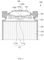
- a secondary battery 100 according to the first embodiment of the present invention comprises an electrode assembly 110, an electrolyte 120, a can 130 for accommodating the electrode assembly 110 and the electrolyte 120, and a cap assembly 140 mounted to an opening portion of the can 130.
- the electrode assembly 110 has a structure provided with a positive electrode tab. That is, the electrode assembly 110 may have a structure in which a plurality of electrodes and a plurality of separators are stacked alternately and wound in a roll shape. Also, the plurality of electrodes comprise a positive electrode and a negative electrode. Also, the positive electrode is provided with a positive electrode tab 111 coupled to the cap assembly 140, and the negative electrode may be provided with a negative electrode tab coupled to the bottom surface of the can 130.
- the electrolyte 120 is to improve performance of the electrode assembly and is injected into the can 130, and the electrode assembly 110 is impregnated therewith.
- the can 130 has a cylindrical shape with an open upper portion, and comprises an accommodating part at a lower portion thereof which accommodates the electrode assembly 110 and the electrolyte 120 and a sealing part at an upper portion thereof to which the cap assembly 140 is mounted.
- the cap assembly 140 is mounted to the opening portion of the can, and particularly, has a structure capable of discharging to the outside a gas generated inside the can 130 in a secondary battery activating process.
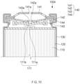
- the cap assembly 140 comprises a top cap 141 which has a top hole 141a vertically passing therethrough, a safety vent 142 which is provided below the top cap 141 and has a vent hole 142a vertically passing therethrough, and a current interrupt device (CID) filter 143 which is provided below the safety vent 142, coupled to the positive electrode tab 111 provided in the electrode assembly 110, has a CID hole 143a vertically passing therethrough.
- the CID hole 143a is closed or opened by the positive electrode tab 111.
- the CID hole 143a is closed when the positive electrode tab 111 is brought into close surface contact with the CID filter 143 comprising the CID hole 143a, and is opened when the positive electrode tab 111 is spaced apart from the CID filter 143 comprising the CID hole 143a.
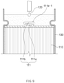
- a long stick-shaped tool 1 passes through the top hole 141a of the top cap 141, the vent hole 142a of the safety vent 142, and the CID hole 143a of CID filter 143, and then may press the positive electrode tab 111 that has closed the CID hole 143a. Accordingly, as the CID hole 143a is opened, the gas generated inside the can 130 may be discharged to the outside through the CID hole 143a, the vent hole 142a, and the top hole 141a. As a result, the secondary battery performance may be significantly improved.
- the CID hole 143a is closed by the positive electrode tab 111 in an activation process, and thus the charging and discharging may be stably performed.
- the gas generated inside the can during the activation process may be discharged to the outside through the cap assembly 140.
- the positive electrode tab 111 and the CID hole 143a are sealed and welded to prevent leakage of the electrolyte.
- the secondary battery 100 comprises the cap assembly 140 having a gas discharging structure.
- the cap-type secondary battery may also discharge the gas generated inside the can to the outside after the activation process, and as a result, the battery performance may be significantly improved.
- the top hole 141a, the vent hole 142a, and the CID hole 143a have minimum diameters enabling the tool 1 to be inserted therein.
- the top hole 141a, the vent hole 142a, and the CID hole 143a may have a diameter of 1-3 mm. Accordingly, the gas inside the can is discharged to the outside, and it is possible to significantly prevent inflow of foreign objects to the top hole 141a, the vent hole 142a, and the CID hole 143a.
- the top hole 141a, the vent hole 142a, the CID hole 143a may be formed on the same vertical line. That is, referring to FIG. 1 , the top hole 141a of the top cap 141, the vent hole 142a of the safety vent 142, and the CID hole 143a of the CID filter 143 are vertically disposed and located on the same vertical line. Accordingly, the positive electrode tab 111 that closes the CID hole 143a may be viewed from the outside through the top hole 141a, the vent hole 142a, and the CID hole 143a, and as a result, whether the CID hole 143a is closed may be easily checked from the outside of the secondary battery.
- the positive electrode tab 111 may be more effectively pressed to open the CID hole 143a.
- the top hole 141a is formed at the central point of the top cap, the vent hole 142a at the central point of the safety vent, and the CID hole 143a at the central point of the CID filter 143. Accordingly, a reduction in strength may be minimized.
- top hole 141a, the vent hole 142a, and the CID hole 143a may be located on the same vertical line.
- halves of the top hole 141a, the vent hole 142a, and the CID hole 143a may be located on the same vertical line, and the other halves may be located on another vertical line. Accordingly, it is possible to significantly prevent an unnecessary object from flowing in through the top hole 141a, the vent hole 142a, and the CID hole 143a, and particularly, it is possible to prevent the positive electrode tab from being pressed by the unnecessary object.
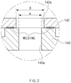
- a diameter ⁇ of the vent hole 142a may be greater than a diameter ⁇ of each of the top hole 141a and the CID hole 143a. That is, when the tool for pressing the positive electrode tab 111 is inserted into the vent hole 142a located in the middle between the top hole 141a and the CID hole 143a, it may be difficult to easily insert the tool due to a flow phenomenon thereof. Accordingly, the vent hole 142a has a diameter greater than those of the top hole 141a and the CID hole 143a, and thus the tool going through the top hole 141a may easily pass therethrough. In particular, it is possible to prevent the vent hole 142a from being damaged by the tool for the pressing the positive electrode tab 111.
- the safety vent 142 is to be cut to prevent explosion of the secondary battery, and a failure may occur due to the damage to the vent hole 142a.
- the vent hole 142a may have a diameter greater than those of the top hole 141a and the CID hole 143a, and accordingly, the damage to the vent hole 142a is prevented.
- the diameter ⁇ of each of the top hole 141a and the CID hole 143a is formed to be 2 mm
- the CID hole 143a is formed to be 3 mm.
- vent hole 142a and the CID hole 143a are connected to each other as the safety vent 142 and the CID filter 143 are coupled, and accordingly, the vent hole 142a and the CID hole 143a may be located on the same vertical line.
- the outer circumferential surface of the vent hole 142a and the outer circumferential surface of the CID hole 143a are sealed and coupled, and accordingly, it is possible to prevent the foreign objects or the electrolyte from leaking into the vent hole 142a and the CID hole 143a through between the safety vent 142 and the CID filter 143.
- the positive electrode tab 111 comprises a lower tab portion 111a and an upper tab portion 111b.
- the lower tab portion 111a is connected to the positive electrode of the electrode assembly 110.
- One end of the upper tab portion 111b connected to the lower tab portion 111a is coupled to the CID filter 143, and the other end closes the CID hole while coming into close surface contact with the bottom surface of the CID filter 143 in which the CID hole 143a is located. That is, after the upper tab portion 111b is brought into close surface contact with the CID filter 143, the one end is coupled to the CID filter 143 by welding, and the other end closes the CID hole while coming into close surface contact with the CID filter 143 comprising the CID hole 143a.
- the CID hole 143a is opened as the other end of the upper tab portion 111b is spaced apart from the CID hole 143a.
- the other end of the upper tab portion 111b closes the CID hole while coming into close surface contact with the CID filter 143 comprising the CID hole 143a again due to a restoring force of the upper tab portion.
- the positive electrode tab 111 may stably close the CID hole until the activation process of the secondary battery, and may be spaced apart from the CID filter 143 after the activation process to open the CID hole.
- the gas inside the can may be simply discharged to the outside.
- the inner circumferential surface of the CID hole 143a and the positive electrode tab 111 may be sealed and coupled. That is, the other end of the upper tab portion 111b in close surface contact with the bottom surface of the CID filter 143 is sealed and coupled to the CID filter 143 after the discharging of gas, and accordingly the CID hole is prevented from opening again. As a result, it is possible to prevent leakage of the electrolyte.
- the positive electrode tab 111 may be made of a material having an elastic restoring force. Accordingly, the other end of the upper tab portion 111b is elastically brought into close surface contact with the bottom surface of the CID filter 143, and as a result, the CID hole 143a may be stably closed. In particular, when the external force of pressing the other end of the upper tab portion 111b is removed, the other end of the upper tab portion 111b rapidly returns to the original position due to the restoring force. As a result, the CID hole 143a may be rapidly and stably closed.
- the positive electrode tab 111 may be alloy steel that contains a material having an elastic restoring force.
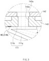
- the positive electrode tab 111 may comprise a sealing protrusion 111b-1 which is to be inserted into the CID hole 143a. That is, the sealing protrusion 111b-1 is to increase a sealing force between the positive electrode tab 111 and the CID hole 143a, has the same diameter as the CID hole 143a, and increases the sealing force between the positive electrode tab 111 and the CID hole 143a while being inserted into the CID hole 143a.
- the sealing protrusion 111b-1 is formed as a hemispherical protrusion portion, and accordingly, the sealing protrusion 111b-1 may be easily coupled to the CID hole 143a or easily separated therefrom.
- a sealing ball 150 is inserted into the CID hole 143a.
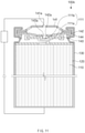
- the sealing ball 150 is to seal the CID hole 143a, has a spherical shape, and here seals the CID hole 143a while being inserted into the CID hole 143a through the top hole 141a and the vent hole 142a.
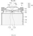
- the sealing ball 150 is melted through a thermal fusing device (not shown), and accordingly the sealing force between the CID hole 143a and the sealing ball 150 may increase as the sealing ball 150 is bonded to the inner circumferential surface of the CID hole 143a.
- the cap assembly 140 may further comprise a closing cover 160 which is to be coupled to the top hole 141a. That is, the closing cover 160 is to increase connectivity of a connection terminal connected to the top cap 141, and is made of the same material as the top cap 141. Accordingly, it is possible to prevent foreign objects from flowing in through the top hole 141a and increase the connectivity of the connection terminal.
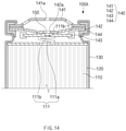
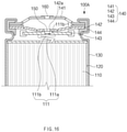
- a method for manufacturing the secondary battery according to the first embodiment of the present invention comprises a cap assembly manufacturing step (S10), an electrode assembly and electrolyte accommodating step (S20), a preliminary battery manufacturing step (S30), an activation step (S40), a gas discharging step (S50), a welding step (S60), a sealing ball inserting step (S70), a bonding step (S80), and a closing step (S90), as illustrated in FIGS. 7 to 16 .
- the cap assembly manufacturing step (S10) comprises a cap assembly perforating process and a cap assembly assembling process.
- a top cap 141 is perforated, by using a perforating device (not shown), to form a top hole 141a that vertically passes through the center of the top surface thereof
- a safety vent 142 is perforated to form a vent hole 142a that vertically passes through the center of the top surface thereof
- a CID filter 143 is perforated to form a CID hole 143a that vertically passes through the center of the top surface thereof.
- the perforation is preformed such that the top hole 141a, the vent hole 142a, and the CID hole 143a are located on the same vertical line when a cap assembly is manufactured. This is so that a tool is stably inserted to go through the top hole 141a, the vent hole 142a, and the CID hole 143a.
- the perforation is performed such that the vent hole 142a has a diameter greater than those of the top hole 141a and the CID hole 143a, and accordingly, it is possible to prevent the vent hole 142a from being damaged by the tool that is going through the top hole 141a.
- the vent hole 142a has a diameter greater than those of the top hole 141a and the CID hole 143a by 1 mm-2 mm.
- the top cap 141 having the top hole 141a is disposed on the top side, the safety vent 142 having the vent hole 142a is disposed below the top cap 141, and then the CID filter 143 having the CID hole 143a is disposed below the safety vent 142.
- the top hole 141a of the top cap 141, the vent hole 142a of the safety vent 142, and the CID hole 143a of the CID filter 143 are located on the same vertical line.
- a gasket 144 is coupled so as to surround the outer circumferential surfaces of the top cap and the safety vent.
- the cap assembly manufacturing step (S10) further comprises a safety vent and CID filter coupling process.
- a bonding device is inserted through the top hole 141a, and then the vent hole 142a and the CID hole 143a are connected by bringing the safety vent 142 into close contact with the top surface of the CID filter 143.
- Heat is applied in a state described above to couple the safety vent 142 and the CID filter 143.
- the safety vent 142 and the CID filter 143 are coupled so as to completely form a seal between the vent hole 142a and the CID hole 143a. That is, the outer circumferential surface of the vent hole and the outer circumferential surface of the CID hole, which correspond to each other, are sealed and coupled.
- the cap assembly manufacturing step (S10) When the cap assembly manufacturing step (S10) is finished, the cap assembly having the top hole, the vent hole, and the CID hole may be manufactured.
- an electrode assembly 110 is accommodated through an opening portion of a can 130, and then an electrolyte 120 is injected into the can 130.
- the electrode assembly 110 is impregnated with the electrolyte.
- the electrode assembly 110 has a structure in which a plurality of electrodes and a plurality of separators are stacked alternately and wound in a roll shape, and the plurality of the electrodes comprise an positive electrode and a negative electrode.
- the positive electrode is provided with a positive electrode tab 111 coupled to the cap assembly 140, and the negative electrode may be provided with a negative electrode tab coupled to the bottom surface of the can 130.
- the preliminary battery manufacturing step (S30) is to manufacture a preliminary battery which has not been charged and discharged, and comprises a disposing process and a coupling process.
- the cap assembly 140 is disposed above the can 130.
- the cap assembly 140 is disposed such that the CID filter 143 of the cap assembly 140 becomes adjacent to the positive electrode tab 111 of the electrode assembly 110.
- the positive electrode tab 111 provided in the electrode assembly 110 is coupled to the CID filter 143 of the cap assembly 140 while closing the CID hole 143a.
- the positive electrode tab 111 comprises a lower tab portion 111a connected to the electrode assembly 110 and an upper tab portion 111b connected to the lower tab portion 111a.
- the upper tab portion 111b is brought into close surface contact with the bottom surface of the CID filter 143a, and then the other end of the upper tab portion 111b is moved to close the CID hole 143a. Subsequently, one end of the upper tab portion 111b is welded and coupled to the bottom surface of the CID filter 143. In other words, the other end of the upper tab portion 111b closes the CID hole 143a while coming into close surface contact with the bottom surface of the CID filter 143 comprising the CID hole 143a, and one end is welded to the CID filter 143a to couple the CID filter and the positive electrode tab.
- the positive electrode tab 111 has an elastic force toward the CID hole 143a, and accordingly, the CID hole 143a may be stably closed.
- the other end of the upper tab portion 111b of the positive electrode tab 111 comprises a sealing protrusion 111b-1 formed of a hemispherical protrusion portion. That is, in the coupling process, the sealing protrusion 111b-1 may be inserted into the CID hole 143a to increase a coupling force and a sealing force between the positive electrode tab and the CID hole.
- the cap assembly 140 is coupled to an opening portion of the can 130.
- a preliminary battery 100A is completed.
- the preliminary battery 100A is activated by charging and discharging.
- a gas is generated inside the can due to interaction between the electrode assembly and the electrolyte, and pressure increases as the gas is accumulated inside the can 130.
- the gas generated inside the can 130 is discharged to the outside through the cap assembly 140 of the preliminary battery 100A. That is, a tool 1 is inserted through the top hole 141a, the vent hole 142a, and the CID hole 143a of the cap assembly 140, and thus the positive electrode tab 111 in close contact with the CID filter 143 is pressed downward.
- the CID hole 143a is opened, the gas generated inside the can 130 is discharged to the outside through the CID hole 143a, the vent hole 142a, and the top hole 141a.
- the CID hole 143a may be closed again as the positive electrode tab 111 returns to the original position.
- the CID hole is closed so that the electrolyte inside the can is not discharged to the outside through the CID hole, the vent hole, and the top hole of the cap assembly. That is, in the welding step (S60), a welding device is inserted through the top hole 141a, the vent hole 142a, and the CID hole 143a of the cap assembly 140, and thus a lower end of the inner circumferential surface of the CID hole 143a is welded to the positive electrode tab 111. In particular, the welding is performed along the inner circumferential surface of the CID hole 143a in close contact with the positive electrode tab 111, and thus a seal is formed between the CID filter 143 and the positive electrode tab 111.
- a sealing ball 150 is forcibly inserted into the CID hole 143a through the top hole 141a and the vent hole 142a.
- the CID hole may be effectively sealed.
- a melting device 2 is inserted through the top hole 141a and the vent hole 142a, and then the sealing ball 150 is partially melted to seal and bond the sealing ball 150 and the CID hole 143a which are in close contact with each other.
- the CID hole may be completely sealed.
- a closing cover 160 is coupled to the top hole 141a to close the top hole 141a.
- the closing cover 160 is made of the same material as the top cap 141.
- the secondary battery in which the gas is discharged out may be manufactured.
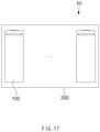
- a battery pack 10 according to the second embodiment of the present invention comprises a secondary battery 100 and a battery case 200 accommodating one or more secondary batteries 100 as illustrated in FIG. 17 .
- the secondary battery 100 has the same components and functions as the secondary battery according to the first embodiment described above, and thus a duplicated description will be omitted.
- the battery pack 10 according to the second embodiment of the present invention comprises the secondary battery in which the gas inside the can is discharged out, and thus the battery performance may be significantly improved.
- a method for manufacturing the battery pack according to the second embodiment of the present invention comprises a step of manufacturing a secondary battery 100 and a step of accommodating the secondary battery 100 in a battery case 200.
- the step of manufacturing the secondary battery 100 has the same method as the method of manufacturing the secondary battery described above, and thus a duplicated description will be omitted.
- the method for manufacturing the battery pack according to the second embodiment of the present invention may manufacture the battery pack 10 that comprises the secondary battery 100 in which the gas in the activation step is discharged out.
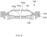
- a cap assembly 140 according the third embodiment of the present invention comprises a top cap 141 which has a top hole 141a vertically passing therethrough, a safety vent 142 which is provided below the top cap 141 and has a vent hole 142a vertically passing therethrough, and a CID filter 143 which is provided below the safety vent 142 and has a CID hole 143a vertically passing therethrough, as illustrated in FIG. 18 .
- the top hole 141a, the vent hole 142a, and the CID hole 143a may be formed on the same vertical line O.
- the cap assembly according to the third embodiment of the present invention has the same components and functions as the cap assembly provided in the secondary battery described above, and thus a duplicated description will be omitted.
- the cap assembly according to the third embodiment of the present invention may discharge to the outside the gas generated inside the can through the top hole 141a, the vent hole 142a, and the CID hole.
Landscapes
- Chemical & Material Sciences (AREA)
- Chemical Kinetics & Catalysis (AREA)
- Electrochemistry (AREA)
- General Chemical & Material Sciences (AREA)
- Engineering & Computer Science (AREA)
- Manufacturing & Machinery (AREA)
- Gas Exhaust Devices For Batteries (AREA)
- Connection Of Batteries Or Terminals (AREA)
- Secondary Cells (AREA)
Applications Claiming Priority (2)
| Application Number | Priority Date | Filing Date | Title |
|---|---|---|---|
| KR1020200014553A KR102706444B1 (ko) | 2020-02-06 | 2020-02-06 | 이차전지 제조방법 및 그를 포함하는 전지팩 제조방법 |
| PCT/KR2021/000754 WO2021157909A1 (ko) | 2020-02-06 | 2021-01-19 | 이차전지 제조방법 및 그를 포함하는 전지팩 제조방법 |
Publications (2)
| Publication Number | Publication Date |
|---|---|
| EP3952016A1 true EP3952016A1 (de) | 2022-02-09 |
| EP3952016A4 EP3952016A4 (de) | 2023-03-08 |
Family
ID=77200712
Family Applications (1)
| Application Number | Title | Priority Date | Filing Date |
|---|---|---|---|
| EP21751234.2A Pending EP3952016A4 (de) | 2020-02-06 | 2021-01-19 | Verfahren zur herstellung einer sekundärbatterie und verfahren zur herstellung eines akkusatzes damit |
Country Status (6)
| Country | Link |
|---|---|
| US (1) | US11757152B2 (de) |
| EP (1) | EP3952016A4 (de) |
| JP (1) | JP7293563B2 (de) |
| KR (1) | KR102706444B1 (de) |
| CN (1) | CN113875056B (de) |
| WO (1) | WO2021157909A1 (de) |
Cited By (2)
| Publication number | Priority date | Publication date | Assignee | Title |
|---|---|---|---|---|
| SE545630C2 (en) * | 2022-12-22 | 2023-11-14 | Northvolt Ab | A controlled ventilating terminal part for a cylindrical secondary cell |
| EP4224622A4 (de) * | 2021-06-03 | 2025-03-12 | LG Energy Solution, Ltd. | Sekundärbatterie und verfahren zur herstellung davon |
Families Citing this family (5)
| Publication number | Priority date | Publication date | Assignee | Title |
|---|---|---|---|---|
| KR102693189B1 (ko) * | 2021-11-02 | 2024-08-09 | 삼성에스디아이 주식회사 | 원통형 이차전지 및 이차전지의 제조방법 |
| KR102809614B1 (ko) * | 2021-11-02 | 2025-05-20 | 삼성에스디아이 주식회사 | 원통형 이차전지 및 이차전지의 제조방법 |
| CN116031587B (zh) | 2023-02-09 | 2023-06-23 | 深圳海润新能源科技有限公司 | 储能装置及用电设备 |
| EP4693633A1 (de) * | 2024-08-07 | 2026-02-11 | VARTA Microbattery GmbH | Herstellungsverfahren, energiespeicherelement und deckelbaugruppe |
| JP7823645B2 (ja) * | 2023-10-13 | 2026-03-04 | トヨタ自動車株式会社 | 電池パック |
Family Cites Families (32)
| Publication number | Priority date | Publication date | Assignee | Title |
|---|---|---|---|---|
| JPH07254402A (ja) | 1994-03-15 | 1995-10-03 | Toshiba Battery Co Ltd | 密閉形電池 |
| EP0849815B1 (de) * | 1996-07-09 | 2005-05-04 | Matsushita Electric Industrial Co., Ltd. | Sekundärzelle mit abdichtplatte |
| JP2003142606A (ja) | 2001-11-07 | 2003-05-16 | Hitachi Ltd | 半導体記憶装置 |
| JP4592315B2 (ja) | 2004-03-29 | 2010-12-01 | 三洋電機株式会社 | 密閉型二次電池 |
| KR100591421B1 (ko) * | 2004-09-07 | 2006-06-21 | 삼성에스디아이 주식회사 | 형상기억 안전벤트를 갖는 리튬 이온 이차 전지 |
| KR100646512B1 (ko) | 2005-03-25 | 2006-11-14 | 삼성에스디아이 주식회사 | 원통형 이차전지 |
| KR100646530B1 (ko) | 2005-04-27 | 2006-11-23 | 삼성에스디아이 주식회사 | 이차 전지 |
| JP4934994B2 (ja) | 2005-06-01 | 2012-05-23 | 新神戸電機株式会社 | 密閉型円柱状二次電池 |
| KR20080032911A (ko) * | 2006-10-11 | 2008-04-16 | 삼성에스디아이 주식회사 | 이차 전지 |
| KR101029841B1 (ko) | 2006-11-13 | 2011-04-15 | 주식회사 엘지화학 | 각형 이차전지의 제조방법 |
| KR101396703B1 (ko) * | 2008-03-05 | 2014-05-19 | 삼성에스디아이 주식회사 | 가스제거장치 및 이를 이용한 원통형 이차전지 |
| KR101073891B1 (ko) | 2008-09-18 | 2011-10-17 | 김재봉 | 원통형 이차전지 |
| US20100216014A1 (en) | 2009-02-24 | 2010-08-26 | Eveready Battery Company, Inc. | Closure Assembly for Electrochemical Cells |
| JP5470142B2 (ja) | 2010-04-01 | 2014-04-16 | 日立ビークルエナジー株式会社 | 二次電池およびその製造方法 |
| US20150072201A1 (en) * | 2010-11-16 | 2015-03-12 | Hitachi, Ltd. | Cylindrical secondary battery |
| JP5673195B2 (ja) | 2011-02-23 | 2015-02-18 | 株式会社Gsユアサ | 電池 |
| WO2012147782A1 (ja) | 2011-04-28 | 2012-11-01 | 三洋電機株式会社 | 密閉型電池及びその製造方法 |
| JP5578371B2 (ja) * | 2011-11-09 | 2014-08-27 | トヨタ自動車株式会社 | 密閉型電池およびその放電方法 |
| CN104009256B (zh) * | 2013-02-27 | 2017-12-15 | 深圳市沃特玛电池有限公司 | 锂离子动力电池的开口化成工艺 |
| CN203398176U (zh) * | 2013-05-24 | 2014-01-15 | 深圳市沃特玛电池有限公司 | 适合开口化成的电池盖帽结构 |
| KR101831004B1 (ko) * | 2013-11-29 | 2018-02-21 | 주식회사 엘지화학 | 원통형 이차전지의 내부 가스 배출장치 및 이를 이용한 가스 배출방법 |
| KR101670364B1 (ko) * | 2014-09-04 | 2016-10-31 | 신흥에스이씨주식회사 | 이차전지용 cid조립체의 제조방법 및 그 조립체 |
| KR101948620B1 (ko) * | 2015-06-05 | 2019-02-15 | 주식회사 엘지화학 | 이차 전지용 캡 어셈블리 |
| KR102459618B1 (ko) | 2015-09-23 | 2022-10-27 | 삼성에스디아이 주식회사 | 이차 전지 |
| KR102072762B1 (ko) | 2015-12-14 | 2020-02-03 | 주식회사 엘지화학 | 캔형 이차전지 및 그를 포함하는 이차전지 모듈 |
| KR101941145B1 (ko) * | 2015-12-16 | 2019-01-23 | 주식회사 엘지화학 | 전지케이스, 이차전지 및 그의 제조방법 |
| KR20180023696A (ko) * | 2016-08-26 | 2018-03-07 | 주식회사 엘지화학 | 이차전지 제조 방법 |
| KR102298013B1 (ko) | 2016-10-11 | 2021-09-06 | 주식회사 엘지에너지솔루션 | 가스켓과 전류차단부재 사이에 향상된 고정 구조를 가진 전류차단부재 어셈블리 및 이를 포함하는 캡 어셈블리 |
| JP6876426B2 (ja) | 2016-12-21 | 2021-05-26 | Fdk株式会社 | アルカリ二次電池 |
| KR101914746B1 (ko) | 2017-12-20 | 2018-11-05 | 주식회사 엘지화학 | 가압부를 포함하는 원통형 전지 및 이의 제조 방법 |
| KR102392396B1 (ko) | 2018-01-09 | 2022-04-29 | 주식회사 엘지에너지솔루션 | 2종의 노치가 형성된 벤트를 포함하는 캡 어셈블리 |
| KR102487217B1 (ko) * | 2018-02-01 | 2023-01-11 | 주식회사 엘지에너지솔루션 | 리벳을 포함하는 캡 어셈블리 및 이를 포함하는 비딩부/클림핑부가 생략된 원통형 전지 |
-
2020
- 2020-02-06 KR KR1020200014553A patent/KR102706444B1/ko active Active
-
2021
- 2021-01-19 EP EP21751234.2A patent/EP3952016A4/de active Pending
- 2021-01-19 CN CN202180003514.0A patent/CN113875056B/zh active Active
- 2021-01-19 WO PCT/KR2021/000754 patent/WO2021157909A1/ko not_active Ceased
- 2021-01-19 JP JP2021561836A patent/JP7293563B2/ja active Active
- 2021-01-19 US US17/609,998 patent/US11757152B2/en active Active
Cited By (3)
| Publication number | Priority date | Publication date | Assignee | Title |
|---|---|---|---|---|
| EP4224622A4 (de) * | 2021-06-03 | 2025-03-12 | LG Energy Solution, Ltd. | Sekundärbatterie und verfahren zur herstellung davon |
| SE545630C2 (en) * | 2022-12-22 | 2023-11-14 | Northvolt Ab | A controlled ventilating terminal part for a cylindrical secondary cell |
| SE2251554A1 (en) * | 2022-12-22 | 2023-11-14 | Northvolt Ab | A controlled ventilating terminal part for a cylindrical secondary cell |
Also Published As
| Publication number | Publication date |
|---|---|
| KR20210100492A (ko) | 2021-08-17 |
| US11757152B2 (en) | 2023-09-12 |
| WO2021157909A1 (ko) | 2021-08-12 |
| JP7293563B2 (ja) | 2023-06-20 |
| CN113875056A (zh) | 2021-12-31 |
| CN113875056B (zh) | 2024-05-17 |
| US20220209342A1 (en) | 2022-06-30 |
| JP2022529468A (ja) | 2022-06-22 |
| EP3952016A4 (de) | 2023-03-08 |
| KR102706444B1 (ko) | 2024-09-13 |
Similar Documents
| Publication | Publication Date | Title |
|---|---|---|
| US11757152B2 (en) | Method for manufacturing secondary battery and method for manufacturing battery pack comprising same | |
| US20260018718A1 (en) | Cap Assembly, Secondary Battery Comprising the Same, and Battery Pack | |
| US20230231242A1 (en) | Secondary battery | |
| KR100947989B1 (ko) | 이차 전지 및 그 제조 방법 | |
| KR102912119B1 (ko) | 원통형 이차전지 및 이차전지의 제조방법 | |
| EP3998674A1 (de) | Sekundärbatterie | |
| JP2022529468A5 (de) | ||
| KR100300405B1 (ko) | 이차전지의캡어셈블리 | |
| KR102702547B1 (ko) | 원통형 이차 전지 | |
| CN117855756A (zh) | 二次电池 | |
| KR102761907B1 (ko) | 이차 전지 | |
| US8592080B2 (en) | Secondary battery | |
| US20230223643A1 (en) | Secondary battery | |
| KR102642157B1 (ko) | 원통형 리튬 이온 이차 전지 | |
| KR102935966B1 (ko) | 이차 전지 | |
| US20250070370A1 (en) | Cylindrical secondary battery and method for manufacturing secondary battery | |
| US20230006292A1 (en) | Battery | |
| KR102693189B1 (ko) | 원통형 이차전지 및 이차전지의 제조방법 | |
| EP4250445A1 (de) | Sekundärbatterie und herstellungsverfahren dafür | |
| KR102900508B1 (ko) | 이차 전지 | |
| KR100659885B1 (ko) | 리튬이온 이차전지 | |
| KR20250151028A (ko) | 원통형 이차 전지 | |
| KR20240156058A (ko) | 원통형 이차 전지 | |
| CN114122576A (zh) | 一种扣式锂二次电池的弧面壳具 |
Legal Events
| Date | Code | Title | Description |
|---|---|---|---|
| STAA | Information on the status of an ep patent application or granted ep patent |
Free format text: STATUS: THE INTERNATIONAL PUBLICATION HAS BEEN MADE |
|
| PUAI | Public reference made under article 153(3) epc to a published international application that has entered the european phase |
Free format text: ORIGINAL CODE: 0009012 |
|
| STAA | Information on the status of an ep patent application or granted ep patent |
Free format text: STATUS: REQUEST FOR EXAMINATION WAS MADE |
|
| 17P | Request for examination filed |
Effective date: 20211105 |
|
| AK | Designated contracting states |
Kind code of ref document: A1 Designated state(s): AL AT BE BG CH CY CZ DE DK EE ES FI FR GB GR HR HU IE IS IT LI LT LU LV MC MK MT NL NO PL PT RO RS SE SI SK SM TR |
|
| RAP3 | Party data changed (applicant data changed or rights of an application transferred) |
Owner name: LG ENERGY SOLUTION, LTD. |
|
| A4 | Supplementary search report drawn up and despatched |
Effective date: 20230202 |
|
| RIC1 | Information provided on ipc code assigned before grant |
Ipc: H01M 50/531 20210101ALI20230127BHEP Ipc: H01M 50/186 20210101ALI20230127BHEP Ipc: H01M 50/184 20210101ALI20230127BHEP Ipc: H01M 10/52 20060101ALI20230127BHEP Ipc: H01M 10/44 20060101ALI20230127BHEP Ipc: H01M 50/152 20210101ALI20230127BHEP Ipc: H01M 50/578 20210101ALI20230127BHEP Ipc: H01M 50/572 20210101ALI20230127BHEP Ipc: H01M 50/342 20210101AFI20230127BHEP |
|
| DAV | Request for validation of the european patent (deleted) | ||
| DAX | Request for extension of the european patent (deleted) |