EP3952003B1 - Battery residual value display device - Google Patents
Battery residual value display device Download PDFInfo
- Publication number
- EP3952003B1 EP3952003B1 EP20781294.2A EP20781294A EP3952003B1 EP 3952003 B1 EP3952003 B1 EP 3952003B1 EP 20781294 A EP20781294 A EP 20781294A EP 3952003 B1 EP3952003 B1 EP 3952003B1
- Authority
- EP
- European Patent Office
- Prior art keywords
- battery
- residual value
- indicating
- information
- residual
- Prior art date
- Legal status (The legal status is an assumption and is not a legal conclusion. Google has not performed a legal analysis and makes no representation as to the accuracy of the status listed.)
- Active
Links
- 238000000034 method Methods 0.000 claims description 42
- 238000004519 manufacturing process Methods 0.000 claims description 35
- 230000008859 change Effects 0.000 claims description 10
- 230000036962 time dependent Effects 0.000 claims description 9
- 238000012937 correction Methods 0.000 claims description 7
- 230000036541 health Effects 0.000 claims description 5
- -1 ... Proteins 0.000 claims description 3
- 101100074846 Caenorhabditis elegans lin-2 gene Proteins 0.000 claims description 3
- 108010088874 Cullin 1 Proteins 0.000 claims description 3
- 102100034032 Cytohesin-3 Human genes 0.000 claims description 3
- 101710160297 Cytohesin-3 Proteins 0.000 claims description 3
- 101100497386 Mus musculus Cask gene Proteins 0.000 claims description 3
- 230000008569 process Effects 0.000 description 36
- 230000006870 function Effects 0.000 description 34
- 238000004364 calculation method Methods 0.000 description 9
- 230000007423 decrease Effects 0.000 description 9
- 238000012545 processing Methods 0.000 description 8
- 230000006866 deterioration Effects 0.000 description 3
- 238000010586 diagram Methods 0.000 description 3
- 238000012423 maintenance Methods 0.000 description 2
- 239000003086 colorant Substances 0.000 description 1
- 238000005516 engineering process Methods 0.000 description 1
- 238000005259 measurement Methods 0.000 description 1
- 230000007246 mechanism Effects 0.000 description 1
- 239000002184 metal Substances 0.000 description 1
- 238000012986 modification Methods 0.000 description 1
- 230000004048 modification Effects 0.000 description 1
- 230000008439 repair process Effects 0.000 description 1
Images


Classifications
-
- G—PHYSICS
- G01—MEASURING; TESTING
- G01R—MEASURING ELECTRIC VARIABLES; MEASURING MAGNETIC VARIABLES
- G01R31/00—Arrangements for testing electric properties; Arrangements for locating electric faults; Arrangements for electrical testing characterised by what is being tested not provided for elsewhere
- G01R31/36—Arrangements for testing, measuring or monitoring the electrical condition of accumulators or electric batteries, e.g. capacity or state of charge [SoC]
- G01R31/392—Determining battery ageing or deterioration, e.g. state of health
-
- G—PHYSICS
- G01—MEASURING; TESTING
- G01R—MEASURING ELECTRIC VARIABLES; MEASURING MAGNETIC VARIABLES
- G01R31/00—Arrangements for testing electric properties; Arrangements for locating electric faults; Arrangements for electrical testing characterised by what is being tested not provided for elsewhere
- G01R31/36—Arrangements for testing, measuring or monitoring the electrical condition of accumulators or electric batteries, e.g. capacity or state of charge [SoC]
- G01R31/371—Arrangements for testing, measuring or monitoring the electrical condition of accumulators or electric batteries, e.g. capacity or state of charge [SoC] with remote indication, e.g. on external chargers
-
- B—PERFORMING OPERATIONS; TRANSPORTING
- B60—VEHICLES IN GENERAL
- B60L—PROPULSION OF ELECTRICALLY-PROPELLED VEHICLES; SUPPLYING ELECTRIC POWER FOR AUXILIARY EQUIPMENT OF ELECTRICALLY-PROPELLED VEHICLES; ELECTRODYNAMIC BRAKE SYSTEMS FOR VEHICLES IN GENERAL; MAGNETIC SUSPENSION OR LEVITATION FOR VEHICLES; MONITORING OPERATING VARIABLES OF ELECTRICALLY-PROPELLED VEHICLES; ELECTRIC SAFETY DEVICES FOR ELECTRICALLY-PROPELLED VEHICLES
- B60L58/00—Methods or circuit arrangements for monitoring or controlling batteries or fuel cells, specially adapted for electric vehicles
- B60L58/10—Methods or circuit arrangements for monitoring or controlling batteries or fuel cells, specially adapted for electric vehicles for monitoring or controlling batteries
- B60L58/12—Methods or circuit arrangements for monitoring or controlling batteries or fuel cells, specially adapted for electric vehicles for monitoring or controlling batteries responding to state of charge [SoC]
-
- B—PERFORMING OPERATIONS; TRANSPORTING
- B60—VEHICLES IN GENERAL
- B60L—PROPULSION OF ELECTRICALLY-PROPELLED VEHICLES; SUPPLYING ELECTRIC POWER FOR AUXILIARY EQUIPMENT OF ELECTRICALLY-PROPELLED VEHICLES; ELECTRODYNAMIC BRAKE SYSTEMS FOR VEHICLES IN GENERAL; MAGNETIC SUSPENSION OR LEVITATION FOR VEHICLES; MONITORING OPERATING VARIABLES OF ELECTRICALLY-PROPELLED VEHICLES; ELECTRIC SAFETY DEVICES FOR ELECTRICALLY-PROPELLED VEHICLES
- B60L58/00—Methods or circuit arrangements for monitoring or controlling batteries or fuel cells, specially adapted for electric vehicles
- B60L58/10—Methods or circuit arrangements for monitoring or controlling batteries or fuel cells, specially adapted for electric vehicles for monitoring or controlling batteries
- B60L58/16—Methods or circuit arrangements for monitoring or controlling batteries or fuel cells, specially adapted for electric vehicles for monitoring or controlling batteries responding to battery ageing, e.g. to the number of charging cycles or the state of health [SoH]
-
- G—PHYSICS
- G01—MEASURING; TESTING
- G01R—MEASURING ELECTRIC VARIABLES; MEASURING MAGNETIC VARIABLES
- G01R13/00—Arrangements for displaying electric variables or waveforms
- G01R13/02—Arrangements for displaying electric variables or waveforms for displaying measured electric variables in digital form
-
- G—PHYSICS
- G01—MEASURING; TESTING
- G01R—MEASURING ELECTRIC VARIABLES; MEASURING MAGNETIC VARIABLES
- G01R31/00—Arrangements for testing electric properties; Arrangements for locating electric faults; Arrangements for electrical testing characterised by what is being tested not provided for elsewhere
- G01R31/36—Arrangements for testing, measuring or monitoring the electrical condition of accumulators or electric batteries, e.g. capacity or state of charge [SoC]
- G01R31/3644—Constructional arrangements
- G01R31/3646—Constructional arrangements for indicating electrical conditions or variables, e.g. visual or audible indicators
-
- G—PHYSICS
- G01—MEASURING; TESTING
- G01R—MEASURING ELECTRIC VARIABLES; MEASURING MAGNETIC VARIABLES
- G01R31/00—Arrangements for testing electric properties; Arrangements for locating electric faults; Arrangements for electrical testing characterised by what is being tested not provided for elsewhere
- G01R31/36—Arrangements for testing, measuring or monitoring the electrical condition of accumulators or electric batteries, e.g. capacity or state of charge [SoC]
- G01R31/3644—Constructional arrangements
- G01R31/3647—Constructional arrangements for determining the ability of a battery to perform a critical function, e.g. cranking
-
- G—PHYSICS
- G01—MEASURING; TESTING
- G01R—MEASURING ELECTRIC VARIABLES; MEASURING MAGNETIC VARIABLES
- G01R31/00—Arrangements for testing electric properties; Arrangements for locating electric faults; Arrangements for electrical testing characterised by what is being tested not provided for elsewhere
- G01R31/36—Arrangements for testing, measuring or monitoring the electrical condition of accumulators or electric batteries, e.g. capacity or state of charge [SoC]
- G01R31/3644—Constructional arrangements
- G01R31/3648—Constructional arrangements comprising digital calculation means, e.g. for performing an algorithm
-
- G—PHYSICS
- G01—MEASURING; TESTING
- G01R—MEASURING ELECTRIC VARIABLES; MEASURING MAGNETIC VARIABLES
- G01R31/00—Arrangements for testing electric properties; Arrangements for locating electric faults; Arrangements for electrical testing characterised by what is being tested not provided for elsewhere
- G01R31/36—Arrangements for testing, measuring or monitoring the electrical condition of accumulators or electric batteries, e.g. capacity or state of charge [SoC]
- G01R31/367—Software therefor, e.g. for battery testing using modelling or look-up tables
-
- G—PHYSICS
- G06—COMPUTING; CALCULATING OR COUNTING
- G06Q—INFORMATION AND COMMUNICATION TECHNOLOGY [ICT] SPECIALLY ADAPTED FOR ADMINISTRATIVE, COMMERCIAL, FINANCIAL, MANAGERIAL OR SUPERVISORY PURPOSES; SYSTEMS OR METHODS SPECIALLY ADAPTED FOR ADMINISTRATIVE, COMMERCIAL, FINANCIAL, MANAGERIAL OR SUPERVISORY PURPOSES, NOT OTHERWISE PROVIDED FOR
- G06Q10/00—Administration; Management
- G06Q10/04—Forecasting or optimisation specially adapted for administrative or management purposes, e.g. linear programming or "cutting stock problem"
-
- G—PHYSICS
- G06—COMPUTING; CALCULATING OR COUNTING
- G06Q—INFORMATION AND COMMUNICATION TECHNOLOGY [ICT] SPECIALLY ADAPTED FOR ADMINISTRATIVE, COMMERCIAL, FINANCIAL, MANAGERIAL OR SUPERVISORY PURPOSES; SYSTEMS OR METHODS SPECIALLY ADAPTED FOR ADMINISTRATIVE, COMMERCIAL, FINANCIAL, MANAGERIAL OR SUPERVISORY PURPOSES, NOT OTHERWISE PROVIDED FOR
- G06Q10/00—Administration; Management
- G06Q10/30—Administration of product recycling or disposal
-
- G—PHYSICS
- G06—COMPUTING; CALCULATING OR COUNTING
- G06Q—INFORMATION AND COMMUNICATION TECHNOLOGY [ICT] SPECIALLY ADAPTED FOR ADMINISTRATIVE, COMMERCIAL, FINANCIAL, MANAGERIAL OR SUPERVISORY PURPOSES; SYSTEMS OR METHODS SPECIALLY ADAPTED FOR ADMINISTRATIVE, COMMERCIAL, FINANCIAL, MANAGERIAL OR SUPERVISORY PURPOSES, NOT OTHERWISE PROVIDED FOR
- G06Q30/00—Commerce
- G06Q30/02—Marketing; Price estimation or determination; Fundraising
- G06Q30/0278—Product appraisal
-
- G—PHYSICS
- G06—COMPUTING; CALCULATING OR COUNTING
- G06Q—INFORMATION AND COMMUNICATION TECHNOLOGY [ICT] SPECIALLY ADAPTED FOR ADMINISTRATIVE, COMMERCIAL, FINANCIAL, MANAGERIAL OR SUPERVISORY PURPOSES; SYSTEMS OR METHODS SPECIALLY ADAPTED FOR ADMINISTRATIVE, COMMERCIAL, FINANCIAL, MANAGERIAL OR SUPERVISORY PURPOSES, NOT OTHERWISE PROVIDED FOR
- G06Q50/00—Information and communication technology [ICT] specially adapted for implementation of business processes of specific business sectors, e.g. utilities or tourism
- G06Q50/06—Energy or water supply
-
- G—PHYSICS
- G06—COMPUTING; CALCULATING OR COUNTING
- G06Q—INFORMATION AND COMMUNICATION TECHNOLOGY [ICT] SPECIALLY ADAPTED FOR ADMINISTRATIVE, COMMERCIAL, FINANCIAL, MANAGERIAL OR SUPERVISORY PURPOSES; SYSTEMS OR METHODS SPECIALLY ADAPTED FOR ADMINISTRATIVE, COMMERCIAL, FINANCIAL, MANAGERIAL OR SUPERVISORY PURPOSES, NOT OTHERWISE PROVIDED FOR
- G06Q50/00—Information and communication technology [ICT] specially adapted for implementation of business processes of specific business sectors, e.g. utilities or tourism
- G06Q50/40—Business processes related to the transportation industry
-
- H—ELECTRICITY
- H01—ELECTRIC ELEMENTS
- H01M—PROCESSES OR MEANS, e.g. BATTERIES, FOR THE DIRECT CONVERSION OF CHEMICAL ENERGY INTO ELECTRICAL ENERGY
- H01M10/00—Secondary cells; Manufacture thereof
- H01M10/42—Methods or arrangements for servicing or maintenance of secondary cells or secondary half-cells
- H01M10/48—Accumulators combined with arrangements for measuring, testing or indicating the condition of cells, e.g. the level or density of the electrolyte
-
- B—PERFORMING OPERATIONS; TRANSPORTING
- B60—VEHICLES IN GENERAL
- B60L—PROPULSION OF ELECTRICALLY-PROPELLED VEHICLES; SUPPLYING ELECTRIC POWER FOR AUXILIARY EQUIPMENT OF ELECTRICALLY-PROPELLED VEHICLES; ELECTRODYNAMIC BRAKE SYSTEMS FOR VEHICLES IN GENERAL; MAGNETIC SUSPENSION OR LEVITATION FOR VEHICLES; MONITORING OPERATING VARIABLES OF ELECTRICALLY-PROPELLED VEHICLES; ELECTRIC SAFETY DEVICES FOR ELECTRICALLY-PROPELLED VEHICLES
- B60L2250/00—Driver interactions
- B60L2250/16—Driver interactions by display
-
- H—ELECTRICITY
- H02—GENERATION; CONVERSION OR DISTRIBUTION OF ELECTRIC POWER
- H02J—CIRCUIT ARRANGEMENTS OR SYSTEMS FOR SUPPLYING OR DISTRIBUTING ELECTRIC POWER; SYSTEMS FOR STORING ELECTRIC ENERGY
- H02J7/00—Circuit arrangements for charging or depolarising batteries or for supplying loads from batteries
- H02J7/0047—Circuit arrangements for charging or depolarising batteries or for supplying loads from batteries with monitoring or indicating devices or circuits
- H02J7/005—Detection of state of health [SOH]
-
- Y—GENERAL TAGGING OF NEW TECHNOLOGICAL DEVELOPMENTS; GENERAL TAGGING OF CROSS-SECTIONAL TECHNOLOGIES SPANNING OVER SEVERAL SECTIONS OF THE IPC; TECHNICAL SUBJECTS COVERED BY FORMER USPC CROSS-REFERENCE ART COLLECTIONS [XRACs] AND DIGESTS
- Y02—TECHNOLOGIES OR APPLICATIONS FOR MITIGATION OR ADAPTATION AGAINST CLIMATE CHANGE
- Y02E—REDUCTION OF GREENHOUSE GAS [GHG] EMISSIONS, RELATED TO ENERGY GENERATION, TRANSMISSION OR DISTRIBUTION
- Y02E60/00—Enabling technologies; Technologies with a potential or indirect contribution to GHG emissions mitigation
- Y02E60/10—Energy storage using batteries
-
- Y—GENERAL TAGGING OF NEW TECHNOLOGICAL DEVELOPMENTS; GENERAL TAGGING OF CROSS-SECTIONAL TECHNOLOGIES SPANNING OVER SEVERAL SECTIONS OF THE IPC; TECHNICAL SUBJECTS COVERED BY FORMER USPC CROSS-REFERENCE ART COLLECTIONS [XRACs] AND DIGESTS
- Y02—TECHNOLOGIES OR APPLICATIONS FOR MITIGATION OR ADAPTATION AGAINST CLIMATE CHANGE
- Y02T—CLIMATE CHANGE MITIGATION TECHNOLOGIES RELATED TO TRANSPORTATION
- Y02T10/00—Road transport of goods or passengers
- Y02T10/60—Other road transportation technologies with climate change mitigation effect
- Y02T10/70—Energy storage systems for electromobility, e.g. batteries
-
- Y—GENERAL TAGGING OF NEW TECHNOLOGICAL DEVELOPMENTS; GENERAL TAGGING OF CROSS-SECTIONAL TECHNOLOGIES SPANNING OVER SEVERAL SECTIONS OF THE IPC; TECHNICAL SUBJECTS COVERED BY FORMER USPC CROSS-REFERENCE ART COLLECTIONS [XRACs] AND DIGESTS
- Y02—TECHNOLOGIES OR APPLICATIONS FOR MITIGATION OR ADAPTATION AGAINST CLIMATE CHANGE
- Y02W—CLIMATE CHANGE MITIGATION TECHNOLOGIES RELATED TO WASTEWATER TREATMENT OR WASTE MANAGEMENT
- Y02W30/00—Technologies for solid waste management
- Y02W30/50—Reuse, recycling or recovery technologies
- Y02W30/84—Recycling of batteries or fuel cells
-
- Y—GENERAL TAGGING OF NEW TECHNOLOGICAL DEVELOPMENTS; GENERAL TAGGING OF CROSS-SECTIONAL TECHNOLOGIES SPANNING OVER SEVERAL SECTIONS OF THE IPC; TECHNICAL SUBJECTS COVERED BY FORMER USPC CROSS-REFERENCE ART COLLECTIONS [XRACs] AND DIGESTS
- Y02—TECHNOLOGIES OR APPLICATIONS FOR MITIGATION OR ADAPTATION AGAINST CLIMATE CHANGE
- Y02W—CLIMATE CHANGE MITIGATION TECHNOLOGIES RELATED TO WASTEWATER TREATMENT OR WASTE MANAGEMENT
- Y02W90/00—Enabling technologies or technologies with a potential or indirect contribution to greenhouse gas [GHG] emissions mitigation
Definitions
- the present invention relates to a device that displays a residual value of a battery.
- Patent Literature 1 A system that determines residual values of an electric vehicle and a hybrid vehicle is conventionally known (e.g., see Patent Literature 1).
- the system according to Patent Literature 1 can determine a residual value of a secondary battery based on deterioration parameters of the battery for determining the residual values of the electric vehicle and the hybrid vehicle.
- Patent Literature 1 Japanese Patent Application Laid-Open No. 2006-197765
- a residual value of a driving battery is an important factor in determining the residual values of the electric vehicle and the hybrid vehicle, it is strongly desired that a user be informed of an accurate residual value of the battery in an easy-to-understand manner.
- Patent Literature 1 determines the residual value of the secondary battery based on deterioration parameters, but does not consider to display the determined residual value to the user in an easy-to-understand manner.
- Patent Document 1 cannot inform the user of the determined residual value in an easy-to-understand manner.
- the object of the present invention is to provide a battery residual value display device that can display an accurate residual value of a battery to a user in an easy-to-understand manner.
- a battery residual value display device includes: a battery information receiving module configured to receive a first residual value indicating a state of health (SOH) of a battery that is a display target of a residual value, information on an elapsed time from a time of manufacture of the battery, and information on a service life of the battery; an attenuation function determining module configured to determine, by using the information on the elapsed time from the time of manufacture of the battery and the information on the service life of the battery received by the battery information receiving module and an attenuation function indicating a time-dependent change of SOH specific to the battery, an attenuation coefficient that is used for correction of the first residual value of the battery; a second residual value determining module configured to correct the first residual value by using the attenuation coefficient to determine a second residual value; a graph output module configured to output a graph of which one axis indicates residual values of the battery and another axis indicates the information on the elapsed time from the time of manufacture of the battery; and
- the graph output module is configured to output: in the graph, a display indicating the first residual value of the battery; a display indicating boundaries between a plurality of residual value ranks obtained by dividing the residual values of the battery in accordance with a level of the second residual value; and a display indicating boundaries between a plurality of groups, indicating types of applications in which the battery can be used, obtained by dividing the plurality of residual value ranks in accordance with the level of the second residual value.
- the first residual value indicating the SOH of the battery that is a display target of the residual value, the information on the elapsed time from the time of manufacture of the battery, and the information on the service life of the battery are received by the battery information receiving module.
- the attenuation coefficient that is used for correction of the first residual value of the battery is determined by the attenuation function determining module.
- the first residual value is corrected by using the attenuation coefficient to determine the second residual value by the second residual value determining module.
- the user can know the accurate residual value of the battery in consideration of the age of the battery.
- the graph of which one axis indicates the residual values of the battery and another axis indicates the information on the elapsed time from the time of manufacture of the battery is output by the graph output module and is displayed on the display unit.
- a display indicating the first residual value of the battery a display indicating boundaries between a plurality of residual value ranks obtained by dividing the residual values of the battery in accordance with a level of the second residual value, and a display indicating boundaries between a plurality of groups, indicating types of applications in which the battery can be used, obtained by dividing the plurality of residual value ranks in accordance with the level of the second residual value are output in the graph by the graph output module.
- the graph output module is preferably configured to divide the plurality of groups indicating the types of applications into at least a first group indicating that the battery can continue to be used in a current application thereof, a second group indicating that the battery cannot be used in the current application but has another application, and a third group indicating that the battery cannot be used in the current application and does not have the other application.
- the plurality of groups indicating the types of applications are divided and output by the graph output module into at least the first group indicating that the battery can continue to be used in a current application thereof, the second group indicating that the battery cannot be used in the current application but has another application, and the third group indicating that the battery cannot be used in the current application and does not have the other application
- the user of the battery residual value display device can be informed of whether the battery that is a display target of the residual value can continue to be used in the current application or can be used in a method other than discarding in an easy-to-understand manner.
- the residual value of the battery and the corresponding application of the battery can be displayed to the user in an easy-to-understand manner.
- the device preferably includes a future residual value calculating module configured to calculate predicted values of the first residual value of the battery at multiple time points in future by using the first residual value and the attenuation function of the battery, and the graph output module is preferably configured to output in the graph a display indicating the predicted values of the first residual value calculated by the future residual value calculating module at the multiple time points in the future.
- the predicted values of the first residual value of the battery at the multiple time points in the future are calculated by the future residual value calculating module by using the first residual value and the attenuation coefficient of the battery.
- a display indicating the predicted values of the first residual value calculated by the future residual value calculating module at the multiple time points in the future are output by the graph output module in the graph.
- the user can intuitively know the current and future residual values of the battery.
- the current and future residual values of the battery can be displayed to the user in an easy-to-understand manner.
- a battery residual value display device will be described with reference to the drawings.
- the same components may be designated by the same reference numbers and descriptions thereof may be omitted.
- the battery residual value display device according to the present embodiment is configured by a user device 10.
- the user device 10 is, for example, a computer that includes a user device controller 110, a display unit 130, and an input unit 150.
- the user device 10 may be a dedicated terminal used for displaying the residual value of a battery, or may be a general-purpose device such as a personal computer, a smartphone, and a tablet terminal.
- the user device controller 110 is configured to include "an arithmetic processing unit such as a central processing unit (CPU)", a memory, an input/output (I/O) unit, and the like.
- the user device controller 110 functions as a battery information receiving module 111, an attenuation function determining module 113, a second residual value determining module 115, a graph output module 117, and a future residual value calculating module 119, by reading and executing a predetermined program.
- the battery information receiving module 111 receives: a first residual value indicating a state of health (SOH) of a battery that is a display target of a residual value; information on an elapsed time from the time of manufacture of the battery; and information on the service life of the battery, from a battery information providing device 30, for example.
- SOH state of health
- Any mechanism that acquires information for determining SOH of a battery from the battery, determines the SOH of the battery based on the information, and provides to the battery information receiving module 111 the determined SOH, the information on the elapsed time from the time of manufacture of the battery, and the information on the service life of the battery can be used as the battery information providing device 30.
- the attenuation function determining module 113 determines an attenuation function that is used for correction of the first residual value of the battery and indicates a time-dependent change of the SOH specific to the battery.
- the second residual value determining module 115 corrects the first residual value by using the attenuation function to determine the second residual value.
- the future residual value calculating module 119 calculates predicted values of the first residual value of the battery at the multiple time points in the future by using the first residual value and the attenuation coefficient of the battery.
- the display unit 130 displays the graph output from the graph output module 117.
- the input unit 150 is, for example, a switch, a button, a touch panel, a keyboard and a mouse, or a microphone, which accepts the input of an operation that is performed onto the user device 10 by a user U.
- a battery information reception process for receiving: the voltage, current, and temperature of a battery that is a determination target of a residual value; information on an elapsed time from the time of manufacture of the battery; and information on the service life of the battery is executed in accordance with an operation of the user U (S110 in FIG. 2 ).
- an attenuation function determination process for determining an attenuation function which is used for correction of a first residual value of the battery and indicates a time-dependent change of SOH specific to the battery, is executed based on the information on the elapsed time from the time of manufacture of the battery and the information on the service life of the battery received by the battery information receiving module 111 (S130 in FIG. 2 ).
- a second residual value determination process for correcting the first residual value by using the attenuation function to determine a second residual value is executed (S150 in FIG. 2 ).
- a future residual value calculation process for calculating predicted values of the first residual value of the battery at multiple time points in the future by using the first residual value and the attenuation coefficient of the battery is executed if needed (S170 in FIG. 2 ).
- a graph output process for outputting to the display unit 130 a graph of which one axis indicates the residual values of the battery and another axis indicates the information on the elapsed time from the time of manufacture of the battery is executed (S190 in FIG. 2 ), and a series of processes by the battery residual value display device is terminated.
- the user device 10 is activated in accordance with an operation of the user U, and in a state where the user device 10 and the battery information providing device 30 are connected to each other, for example, a battery information reception process is started by performing an operation to start the battery information reception process.
- the battery information receiving module 111 receives a first residual value indicating SOH of a battery that is a display target of the residual value, information on an elapsed time from the time of manufacture of the battery, and information on the service life of the battery from the battery information providing device 30, and terminates the process.
- An attenuation function determination process is started by, for example, the termination of the battery information reception process.
- the attenuation function determining module 113 determines an attenuation function, which is used for correction of the first residual value of the battery and indicates a time-dependent change of the SOH specific to the battery, based on the information on the elapsed time from the time of manufacture of the battery and the information on the service life of the battery received by the battery information receiving module 111.
- the attenuation function determined by the attenuation function determining module 113 is a function that indicates the time-dependent change of the SOH specific to the battery
- the attenuation function may employ: a first-order expression or a multi-order expression of which variables are the information on the elapsed time from the time of manufacture of the battery and the information on the service life of the battery; a function that further uses other variables; or various methods such as a model and an approximate expression that are obtained by analyzing a correlation between the SOH and the information on the elapsed time from the time of manufacture of the battery and the service life of the battery.
- the attenuation function of the present embodiment is represented by the following sigmoid function expression, for example.
- y 1 1 + e a x ⁇ b
- y is an attenuation coefficient of the battery
- a is a constant
- b is a value that indicates a service life of the battery
- e is the number of Napier
- x is a value that indicates the elapsed time from the time of manufacture of the battery in years.
- the attenuation function determining module 113 acquires a constant a previously stored in the user device 10, for example, and determines the attenuation function by using: the acquired constant a; a value indicating the service life of the battery included in the information received from the battery information providing device 30 by the battery information receiving module 111; and a value obtained by converting into years the information indicating the elapsed time from the time of manufacture of the battery received from the battery information providing device 30 by the battery information receiving module 111.
- the attenuation function determining module 113 determines an attenuation coefficient y by using Expression (1) and terminates the process.
- the amount of future maintenance costs of the battery is an important factor in determining the residual value of the battery. Then, when the battery breaks down after the end of its service life, the owner of the battery cannot take the manufacturer's warranty and thus bears a maintenance cost. For that reason, the elapsed time from the time of manufacture of the battery and the service life of the battery, which is the determination target of the residual value, are an important factor when the residual value of the battery is accurately determined.
- the residual value of the battery does not necessarily decrease linearly in accordance with the elapsed time from the time of manufacture. Immediately after sale, namely, after a slight drop at the timing of getting out of the new state, the residual value gently decreases at a certain initial stage that is still as good as new, and then rapidly decreases toward a service life in which free repairs by the manufacturer cannot be received.
- the residual value of the battery continues to decrease suddenly after the passage of the service life.
- rare metal etc. included in the battery can be recycled even if the battery cannot be eventually used as a battery, the rate of decrease in the residual value of the battery decreases gradually in the final phase of a battery lifetime because the residual value is not lost.
- the residual value of the battery slowly decreases at an early stage and then suddenly decreases, but in the final phase of its lifetime, it is more realistic that the residual value changes while drawing a curve that continues to maintain a certain degree of residual value.
- the curve of the time-dependent change in the residual value of the battery as described above can be easily approximated because Expression (1) is used as the attenuation function.
- a second residual value determination process is started by the termination of the attenuation function determination process.
- the second residual value determining module 115 determines, as a second residual value of the battery, a value obtained by multiplying the attenuation coefficient y determined in the attenuation function determination process by the first residual value of the battery received by the battery information receiving module 111, and terminates the process.
- the user U can know the accurate residual value of the battery in consideration of the age of the battery.
- a future residual value calculation process is started if needed after the termination of the second residual value determination process.
- the future residual value calculating module 119 calculates predicted values of the first residual value of the battery at the multiple time points in the future by using the first residual value and the attenuation coefficient of the battery, and terminates the process.
- the user U of the battery residual value display device can be informed of estimated results of change in a future residual value of the battery that is the determination target of the residual value in an easy-to-understand manner.
- the constant a of Equation (1) is 0.4
- the value b indicating the service life of the battery is 10 (years)
- the elapsed time from the time of manufacture of the battery at the time of processing is 2 (years)
- the first residual value of the battery received by the battery information receiving module 111 is 0.9500
- the calculation result by Expression (1) is 0.9608 when the calculation result is calculated to the fourth decimal place.
- the future residual value calculating module 119 calculates the predicted values of the first residual value of the battery at the multiple time points in the future considering that the decrease in the SOH of the battery is about 0.0108 ahead of the calculated theoretical value.
- the future residual value calculating module 119 calculates, to be 0.9427, the estimated value of the first residual value of the third-year battery to the fourth decimal place by Expression (1).
- the future residual value calculating module 119 calculates, from the fourth year, the predicted values of the first residual value up to twice the service life (up to the 20th year in the embodiment) for example.
- a graph output process is started by the termination of the second residual value output process, or by the termination of the future residual value calculation process when the future residual value calculation process is executed.
- the graph output module 117 When the graph output process is started, the graph output module 117 outputs information indicating a graph of which a vertical axis indicates residual values of the battery that is a display target of the residual value and a horizontal axis indicates the information on the elapsed time from the time of manufacture of the battery, and terminates the process.
- the graph output module 117 outputs: in the graph, a display indicating the first residual value of the battery; a display indicating boundaries between a plurality of residual value ranks obtained by dividing the residual values of the battery in accordance with a level of the second residual value; and a display indicating boundaries between a plurality of groups, indicating types of applications in which the battery can be used, obtained by dividing the plurality of residual value ranks in accordance with the level of the second residual value.
- the graph output module 117 outputs in the graph a display indicating boundaries between groups that are divided into at least a first group indicating that the battery can continue to be used in a current application thereof, a second group indicating that the battery cannot be used in the current application but has another application, and a third group indicating that the battery cannot be used in the current application and does not have the other application.
- the user U of the battery residual value display device can be informed of whether the battery that is a display target of the residual value can continue to be used in the current application or can be used in a method other than discarding in an easy-to-understand manner.
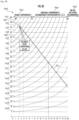
- the graph output module 117 displays a graph Gra1 as illustrated in FIG. 3A on the display unit 130, for example.
- FIG. 3A illustrates the graph Gra1 of which the vertical axis indicates, in a unit of %, the first residual values of the battery that is a display target of the residual value and the horizontal axis indicates, in units of years, values of the elapsed time from the time of manufacture of the battery (hereinafter, "elapsed time").
- the graph Gra1 includes border lines Lin1, Lin2, ..., and Lin19 that are displays indicating boundaries between residual value ranks divided into 100% to 95%, less than 95% to 90%, and so on in 5% increments in accordance with the value of the second residual value of the battery.
- the border line Lin1 indicates a boundary of what percentage or more the value of the first residual value should be in each elapsed time.
- a value of the first residual value at the boundary of the border line Lin1 is 92.47%. This value is a value obtained by multiplying the attenuation coefficient (0.9734) when the elapsed time is 1 year by 95%.
- a value of the first residual value at the boundary of the border line Lin1 in each case where the elapsed period is 2 years or more is calculated in the graph output process, and the border line Lin1 that connects the values in these elapsed times is included in the graph Gra1.
- the border lines Lin2, ..., and Lin19 that are calculated in such a similar method are included in the graph Gra1 as displays that indicate boundaries between residual value ranks.
- a display Val1 indicating the first residual value of the battery that is the determination target of a residual value is included in the graph Gra1.
- the display Val1 indicates that a duration of service is 2 years and the first residual value is 95% in a unit of %.
- the graph Gra1 includes displays Grp1, Grp2, and Grp3 that indicate boundaries between three groups, indicating types of applications in which the battery that is the determination target of the residual value can be used, obtained by dividing the residual value ranks in accordance with the level of the second residual value.
- the display Grp1 indicates a range included in the first group that indicates that the battery can continue to be used in the current application thereof. A battery of which the second residual value is 75% or more is included in this range.
- the display Grp2 indicates a range included in the second group that indicates that the battery cannot be used in the current application but has another application. A battery of which the second residual value is less than 75% and not less than 30% is included in this range.
- the display Grp3 indicates a range included in the third group that indicates that the battery cannot be used in the current application and does not have the other application. A battery of which the second residual value is less than 30% is included in this range.
- the graph Gra1 includes a display Est indicating first residual values at multiple time points in the future of the battery that is the determination target of a residual value, which are estimated by the future residual value calculating module 119.
- a display Val2 indicating the second residual value of the battery at the time of processing may be included in the graph Gra1.
- FIG. 3B illustrates the content of a graph Gra2 when the attenuation function determining module 113 is configured to determine an attenuation coefficient by using Equation (2) as an attenuation function instead of Expression (1).
- y 1 ⁇ x ⁇ 1 ⁇ c / 2 b
- y is an attenuation coefficient of a battery
- b is a value indicated by a service life of the battery
- c is a value indicating a residual rate of the first residual value after a period of twice the service life of the battery has elapsed
- "x” is a value indicating an elapsed time from the time of manufacture of the battery.
- calculation is performed assuming that "b” is 10 (years) and "c" is 30%.
- the present invention can provide the battery residual value display device that can display the accurate residual value of the battery to the user in an easy-to-understand manner.
- the battery information receiving module 111 may be configured to receive, via the input unit 150, the first residual value indicating the SOH of the battery that is a display target of the residual value by the operation of the user U himself, the information on the elapsed time from the time of manufacture of the battery, and the information on the service life of the battery.
- the graph output module 117 may be configured to display the boundaries between the plurality of residual value ranks obtained by dividing the residual values of the battery in accordance with the level of the second residual value by outputting areas indicating residual value ranks adjacent to each other in different colors, patterns, and brightness.
- the present invention is not limited to this.
- the graph output module 117 may be configured to display in the graph a letter (A rank etc. in case of 100% to 95%) indicating a rank corresponding to the second residual value, a number (4 of 5 stages in case of less than 95% and 90% or more), or another symbol, in addition to or in place of displaying the value of the second residual value in a unit of %.
Landscapes
- Engineering & Computer Science (AREA)
- General Physics & Mathematics (AREA)
- Physics & Mathematics (AREA)
- Business, Economics & Management (AREA)
- Strategic Management (AREA)
- Economics (AREA)
- Human Resources & Organizations (AREA)
- General Business, Economics & Management (AREA)
- Theoretical Computer Science (AREA)
- Marketing (AREA)
- Tourism & Hospitality (AREA)
- General Chemical & Material Sciences (AREA)
- Electrochemistry (AREA)
- Chemical Kinetics & Catalysis (AREA)
- Chemical & Material Sciences (AREA)
- Manufacturing & Machinery (AREA)
- Health & Medical Sciences (AREA)
- Development Economics (AREA)
- Entrepreneurship & Innovation (AREA)
- Sustainable Development (AREA)
- Life Sciences & Earth Sciences (AREA)
- General Health & Medical Sciences (AREA)
- Transportation (AREA)
- Finance (AREA)
- Power Engineering (AREA)
- Operations Research (AREA)
- Mechanical Engineering (AREA)
- Primary Health Care (AREA)
- Quality & Reliability (AREA)
- Sustainable Energy (AREA)
- Accounting & Taxation (AREA)
- Game Theory and Decision Science (AREA)
- Water Supply & Treatment (AREA)
- Public Health (AREA)
- Tests Of Electric Status Of Batteries (AREA)
- Charge And Discharge Circuits For Batteries Or The Like (AREA)
- Secondary Cells (AREA)
- Electric Propulsion And Braking For Vehicles (AREA)
Description
- The present invention relates to a device that displays a residual value of a battery.
- A system that determines residual values of an electric vehicle and a hybrid vehicle is conventionally known (e.g., see Patent Literature 1).
- The system according to
Patent Literature 1 can determine a residual value of a secondary battery based on deterioration parameters of the battery for determining the residual values of the electric vehicle and the hybrid vehicle. - Patent Literature 1:
Japanese Patent Application Laid-Open No. 2006-197765 - Further relevant prior art is found in
CN 108 845 270 A . - Because a residual value of a driving battery is an important factor in determining the residual values of the electric vehicle and the hybrid vehicle, it is strongly desired that a user be informed of an accurate residual value of the battery in an easy-to-understand manner.
- However, the system of
Patent Literature 1 determines the residual value of the secondary battery based on deterioration parameters, but does not consider to display the determined residual value to the user in an easy-to-understand manner. - Consequently, the system of
Patent Document 1 cannot inform the user of the determined residual value in an easy-to-understand manner. - In view of the problem of the conventional technology, the object of the present invention is to provide a battery residual value display device that can display an accurate residual value of a battery to a user in an easy-to-understand manner.
- A battery residual value display device according to the present invention includes: a battery information receiving module configured to receive a first residual value indicating a state of health (SOH) of a battery that is a display target of a residual value, information on an elapsed time from a time of manufacture of the battery, and information on a service life of the battery; an attenuation function determining module configured to determine, by using the information on the elapsed time from the time of manufacture of the battery and the information on the service life of the battery received by the battery information receiving module and an attenuation function indicating a time-dependent change of SOH specific to the battery, an attenuation coefficient that is used for correction of the first residual value of the battery; a second residual value determining module configured to correct the first residual value by using the attenuation coefficient to determine a second residual value; a graph output module configured to output a graph of which one axis indicates residual values of the battery and another axis indicates the information on the elapsed time from the time of manufacture of the battery; and a display unit configured to display the graph output from the graph output module. The graph output module is configured to output: in the graph, a display indicating the first residual value of the battery; a display indicating boundaries between a plurality of residual value ranks obtained by dividing the residual values of the battery in accordance with a level of the second residual value; and a display indicating boundaries between a plurality of groups, indicating types of applications in which the battery can be used, obtained by dividing the plurality of residual value ranks in accordance with the level of the second residual value.
- Even if the values of SOH (State Of Health) of a battery that is a display target of a residual value are the same, depending on the length of an elapsed time from manufacturing of the battery to the time of measurement, a deterioration rate of the battery after that is greatly different, and consequently the residual value of the battery is greatly different. For that reason, it is necessary to consider the age of the battery, for example, an elapsed time from the time of manufacture of the battery in order to inform a user of the accurate residual value of the battery.
- In the battery residual value display device according to the present invention, the first residual value indicating the SOH of the battery that is a display target of the residual value, the information on the elapsed time from the time of manufacture of the battery, and the information on the service life of the battery are received by the battery information receiving module.
- Then, by using the information on the elapsed time from the time of manufacture of the battery and the information on the service life of the battery received by the battery information receiving module and an attenuation function indicating a time-dependent change of SOH specific to the battery, the attenuation coefficient that is used for correction of the first residual value of the battery is determined by the attenuation function determining module.
- Then, the first residual value is corrected by using the attenuation coefficient to determine the second residual value by the second residual value determining module.
- As a result, the user can know the accurate residual value of the battery in consideration of the age of the battery.
- Moreover, the graph of which one axis indicates the residual values of the battery and another axis indicates the information on the elapsed time from the time of manufacture of the battery is output by the graph output module and is displayed on the display unit.
- In addition, a display indicating the first residual value of the battery, a display indicating boundaries between a plurality of residual value ranks obtained by dividing the residual values of the battery in accordance with a level of the second residual value, and a display indicating boundaries between a plurality of groups, indicating types of applications in which the battery can be used, obtained by dividing the plurality of residual value ranks in accordance with the level of the second residual value are output in the graph by the graph output module.
- As a result, because the accurate residual value of the battery is visualized and displayed, the user can be intuitively informed of the accurate residual value of the battery.
- As described above, according to the present invention, it is possible to display the accurate residual value of the battery to the user in an easy-to-understand manner.
- In the battery residual value display device according to the present invention, the graph output module is preferably configured to divide the plurality of groups indicating the types of applications into at least a first group indicating that the battery can continue to be used in a current application thereof, a second group indicating that the battery cannot be used in the current application but has another application, and a third group indicating that the battery cannot be used in the current application and does not have the other application.
- In the battery residual value display device according to the present invention, the plurality of groups indicating the types of applications are divided and output by the graph output module into at least the first group indicating that the battery can continue to be used in a current application thereof, the second group indicating that the battery cannot be used in the current application but has another application, and the third group indicating that the battery cannot be used in the current application and does not have the other application
- As a result, the user of the battery residual value display device according to the present invention can be informed of whether the battery that is a display target of the residual value can continue to be used in the current application or can be used in a method other than discarding in an easy-to-understand manner.
- As described above, according to the present invention, the residual value of the battery and the corresponding application of the battery can be displayed to the user in an easy-to-understand manner.
- In the battery residual value display device according to the present invention, the device preferably includes a future residual value calculating module configured to calculate predicted values of the first residual value of the battery at multiple time points in future by using the first residual value and the attenuation function of the battery, and the graph output module is preferably configured to output in the graph a display indicating the predicted values of the first residual value calculated by the future residual value calculating module at the multiple time points in the future.
- In the battery residual value display device according to the present invention, the predicted values of the first residual value of the battery at the multiple time points in the future are calculated by the future residual value calculating module by using the first residual value and the attenuation coefficient of the battery.
- Then, a display indicating the predicted values of the first residual value calculated by the future residual value calculating module at the multiple time points in the future are output by the graph output module in the graph.
- As a result, the user can intuitively know the current and future residual values of the battery.
- As described above, according to the present invention, the current and future residual values of the battery can be displayed to the user in an easy-to-understand manner.
-
-
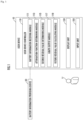
FIG. 1 is a block diagram illustrating an entire configuration of a battery residual value display device. -
FIG. 2 is a flowchart illustrating the contents of processing by the battery residual value display device. -
FIG. 3A is a diagram illustrating an example of the output contents of the battery residual value display device. -
FIG. 3B is a diagram illustrating another example of the output contents of the battery residual value display device. - A battery residual value display device according to the present embodiment will be described with reference to the drawings. Herein, the same components may be designated by the same reference numbers and descriptions thereof may be omitted.
- First, a configuration of the battery residual value display device according to the present embodiment will be described with reference to
FIG. 1 . The battery residual value display device according to the present embodiment is configured by auser device 10. - The
user device 10 is, for example, a computer that includes auser device controller 110, adisplay unit 130, and aninput unit 150. Theuser device 10 may be a dedicated terminal used for displaying the residual value of a battery, or may be a general-purpose device such as a personal computer, a smartphone, and a tablet terminal. - The
user device controller 110 is configured to include "an arithmetic processing unit such as a central processing unit (CPU)", a memory, an input/output (I/O) unit, and the like. Theuser device controller 110 functions as a batteryinformation receiving module 111, an attenuationfunction determining module 113, a second residualvalue determining module 115, a graph output module 117, and a future residualvalue calculating module 119, by reading and executing a predetermined program. - The battery
information receiving module 111 receives: a first residual value indicating a state of health (SOH) of a battery that is a display target of a residual value; information on an elapsed time from the time of manufacture of the battery; and information on the service life of the battery, from a batteryinformation providing device 30, for example. - Any mechanism that acquires information for determining SOH of a battery from the battery, determines the SOH of the battery based on the information, and provides to the battery
information receiving module 111 the determined SOH, the information on the elapsed time from the time of manufacture of the battery, and the information on the service life of the battery can be used as the batteryinformation providing device 30. - Based on the information on the elapsed time from the time of manufacture of the battery and the information on the service life of the battery received by the battery
information receiving module 111, the attenuationfunction determining module 113 determines an attenuation function that is used for correction of the first residual value of the battery and indicates a time-dependent change of the SOH specific to the battery. - The second residual
value determining module 115 corrects the first residual value by using the attenuation function to determine the second residual value. - The graph output module 117 outputs a graph of which one axis indicates the residual values of the battery and another axis indicates the information on the elapsed time from the time of manufacture of the battery.
- The future residual
value calculating module 119 calculates predicted values of the first residual value of the battery at the multiple time points in the future by using the first residual value and the attenuation coefficient of the battery. - The
display unit 130 displays the graph output from the graph output module 117. - The
input unit 150 is, for example, a switch, a button, a touch panel, a keyboard and a mouse, or a microphone, which accepts the input of an operation that is performed onto theuser device 10 by a user U. - Next, an example of the outline of processing of the battery residual value display device will be described with reference to
FIG. 2 . - First, a battery information reception process for receiving: the voltage, current, and temperature of a battery that is a determination target of a residual value; information on an elapsed time from the time of manufacture of the battery; and information on the service life of the battery is executed in accordance with an operation of the user U (S110 in
FIG. 2 ). - Next, an attenuation function determination process for determining an attenuation function, which is used for correction of a first residual value of the battery and indicates a time-dependent change of SOH specific to the battery, is executed based on the information on the elapsed time from the time of manufacture of the battery and the information on the service life of the battery received by the battery information receiving module 111 (S130 in
FIG. 2 ). - Next, a second residual value determination process for correcting the first residual value by using the attenuation function to determine a second residual value is executed (S150 in
FIG. 2 ). - Next, a future residual value calculation process for calculating predicted values of the first residual value of the battery at multiple time points in the future by using the first residual value and the attenuation coefficient of the battery is executed if needed (S170 in
FIG. 2 ). - Then, a graph output process for outputting to the display unit 130 a graph of which one axis indicates the residual values of the battery and another axis indicates the information on the elapsed time from the time of manufacture of the battery is executed (S190 in
FIG. 2 ), and a series of processes by the battery residual value display device is terminated. - Next, the contents of each process will be described with reference to
FIGS. 3A and3B . - The
user device 10 is activated in accordance with an operation of the user U, and in a state where theuser device 10 and the batteryinformation providing device 30 are connected to each other, for example, a battery information reception process is started by performing an operation to start the battery information reception process. - When the battery information reception process is started, the battery
information receiving module 111 receives a first residual value indicating SOH of a battery that is a display target of the residual value, information on an elapsed time from the time of manufacture of the battery, and information on the service life of the battery from the batteryinformation providing device 30, and terminates the process. - An attenuation function determination process is started by, for example, the termination of the battery information reception process.
- When the attenuation function determination process is started, the attenuation
function determining module 113 determines an attenuation function, which is used for correction of the first residual value of the battery and indicates a time-dependent change of the SOH specific to the battery, based on the information on the elapsed time from the time of manufacture of the battery and the information on the service life of the battery received by the batteryinformation receiving module 111. - At this time, if the attenuation function determined by the attenuation
function determining module 113 is a function that indicates the time-dependent change of the SOH specific to the battery, the attenuation function may employ: a first-order expression or a multi-order expression of which variables are the information on the elapsed time from the time of manufacture of the battery and the information on the service life of the battery; a function that further uses other variables; or various methods such as a model and an approximate expression that are obtained by analyzing a correlation between the SOH and the information on the elapsed time from the time of manufacture of the battery and the service life of the battery. However, the attenuation function of the present embodiment is represented by the following sigmoid function expression, for example.
- The attenuation
function determining module 113 acquires a constant a previously stored in theuser device 10, for example, and determines the attenuation function by using: the acquired constant a; a value indicating the service life of the battery included in the information received from the batteryinformation providing device 30 by the batteryinformation receiving module 111; and a value obtained by converting into years the information indicating the elapsed time from the time of manufacture of the battery received from the batteryinformation providing device 30 by the batteryinformation receiving module 111. - Then, the attenuation
function determining module 113 determines an attenuation coefficient y by using Expression (1) and terminates the process. - The amount of future maintenance costs of the battery is an important factor in determining the residual value of the battery. Then, when the battery breaks down after the end of its service life, the owner of the battery cannot take the manufacturer's warranty and thus bears a maintenance cost. For that reason, the elapsed time from the time of manufacture of the battery and the service life of the battery, which is the determination target of the residual value, are an important factor when the residual value of the battery is accurately determined.
- The residual value of the battery does not necessarily decrease linearly in accordance with the elapsed time from the time of manufacture. Immediately after sale, namely, after a slight drop at the timing of getting out of the new state, the residual value gently decreases at a certain initial stage that is still as good as new, and then rapidly decreases toward a service life in which free repairs by the manufacturer cannot be received.
- Then, the residual value of the battery continues to decrease suddenly after the passage of the service life. On the other hand, because rare metal etc. included in the battery can be recycled even if the battery cannot be eventually used as a battery, the rate of decrease in the residual value of the battery decreases gradually in the final phase of a battery lifetime because the residual value is not lost.
- In other words, the residual value of the battery slowly decreases at an early stage and then suddenly decreases, but in the final phase of its lifetime, it is more realistic that the residual value changes while drawing a curve that continues to maintain a certain degree of residual value.
- In the present embodiment, the curve of the time-dependent change in the residual value of the battery as described above can be easily approximated because Expression (1) is used as the attenuation function.
- A second residual value determination process is started by the termination of the attenuation function determination process.
- When the second residual value determination process is started, the second residual
value determining module 115 determines, as a second residual value of the battery, a value obtained by multiplying the attenuation coefficient y determined in the attenuation function determination process by the first residual value of the battery received by the batteryinformation receiving module 111, and terminates the process. - As a result, the user U can know the accurate residual value of the battery in consideration of the age of the battery.
- A future residual value calculation process is started if needed after the termination of the second residual value determination process.
- When the future residual value calculation process is started, the future residual
value calculating module 119 calculates predicted values of the first residual value of the battery at the multiple time points in the future by using the first residual value and the attenuation coefficient of the battery, and terminates the process. - As a result, the user U of the battery residual value display device according to the present invention can be informed of estimated results of change in a future residual value of the battery that is the determination target of the residual value in an easy-to-understand manner.
- More specifically, the case where the constant a of Equation (1) is 0.4, the value b indicating the service life of the battery is 10 (years), the elapsed time from the time of manufacture of the battery at the time of processing is 2 (years), and the first residual value of the battery received by the battery
information receiving module 111 is 0.9500 will be described below. - In this case, the calculation result by Expression (1) is 0.9608 when the calculation result is calculated to the fourth decimal place. However, because the first residual value of the battery received by the battery
information receiving module 111 is 0.9500, the future residualvalue calculating module 119 calculates the predicted values of the first residual value of the battery at the multiple time points in the future considering that the decrease in the SOH of the battery is about 0.0108 ahead of the calculated theoretical value. - In other words, for example, the future residual
value calculating module 119 calculates, to be 0.9427, the estimated value of the first residual value of the third-year battery to the fourth decimal place by Expression (1). However, in consideration of a difference between the first residual value (0.9500) of the battery received by the batteryinformation receiving module 111 and the calculated theoretical value (0.9608) of the SOH of the battery, this value is calculated as the estimated value of the first residual value of the third-year battery = 0.9427 * (0.9500/0.9608) = 0.9320, for example. - Then, the future residual
value calculating module 119 calculates, from the fourth year, the predicted values of the first residual value up to twice the service life (up to the 20th year in the embodiment) for example. - A graph output process is started by the termination of the second residual value output process, or by the termination of the future residual value calculation process when the future residual value calculation process is executed.
- When the graph output process is started, the graph output module 117 outputs information indicating a graph of which a vertical axis indicates residual values of the battery that is a display target of the residual value and a horizontal axis indicates the information on the elapsed time from the time of manufacture of the battery, and terminates the process.
- In addition, the graph output module 117 outputs: in the graph, a display indicating the first residual value of the battery; a display indicating boundaries between a plurality of residual value ranks obtained by dividing the residual values of the battery in accordance with a level of the second residual value; and a display indicating boundaries between a plurality of groups, indicating types of applications in which the battery can be used, obtained by dividing the plurality of residual value ranks in accordance with the level of the second residual value.
- As a result, because the accurate residual value of the battery is visualized and displayed, the user can be intuitively informed of the accurate residual value of the battery.
- At this time, as the plurality of groups indicating the types of applications, the graph output module 117 outputs in the graph a display indicating boundaries between groups that are divided into at least a first group indicating that the battery can continue to be used in a current application thereof, a second group indicating that the battery cannot be used in the current application but has another application, and a third group indicating that the battery cannot be used in the current application and does not have the other application.
- As a result, the user U of the battery residual value display device according to the present invention can be informed of whether the battery that is a display target of the residual value can continue to be used in the current application or can be used in a method other than discarding in an easy-to-understand manner.
- The graph output module 117 displays a graph Gra1 as illustrated in
FIG. 3A on thedisplay unit 130, for example. -
FIG. 3A illustrates the graph Gra1 of which the vertical axis indicates, in a unit of %, the first residual values of the battery that is a display target of the residual value and the horizontal axis indicates, in units of years, values of the elapsed time from the time of manufacture of the battery (hereinafter, "elapsed time"). - The graph Gra1 includes border lines Lin1, Lin2, ..., and Lin19 that are displays indicating boundaries between residual value ranks divided into 100% to 95%, less than 95% to 90%, and so on in 5% increments in accordance with the value of the second residual value of the battery.
- For example, because a value obtained by correcting the first residual value of the battery to the second residual value is the residual value rank of 100% to 95% in the border line Lin1, the border line Lin1 indicates a boundary of what percentage or more the value of the first residual value should be in each elapsed time.
- More specifically, when the elapsed time is 1 year, a value of the first residual value at the boundary of the border line Lin1 is 92.47%. This value is a value obtained by multiplying the attenuation coefficient (0.9734) when the elapsed time is 1 year by 95%.
- Similarly, a value of the first residual value at the boundary of the border line Lin1 in each case where the elapsed period is 2 years or more is calculated in the graph output process, and the border line Lin1 that connects the values in these elapsed times is included in the graph Gra1.
- The border lines Lin2, ..., and Lin19 that are calculated in such a similar method are included in the graph Gra1 as displays that indicate boundaries between residual value ranks.
- Moreover, a display Val1 indicating the first residual value of the battery that is the determination target of a residual value is included in the graph Gra1. In the present embodiment, the display Val1 indicates that a duration of service is 2 years and the first residual value is 95% in a unit of %.
- Moreover, the graph Gra1 includes displays Grp1, Grp2, and Grp3 that indicate boundaries between three groups, indicating types of applications in which the battery that is the determination target of the residual value can be used, obtained by dividing the residual value ranks in accordance with the level of the second residual value.
- In the present embodiment, the display Grp1 indicates a range included in the first group that indicates that the battery can continue to be used in the current application thereof. A battery of which the second residual value is 75% or more is included in this range.
- The display Grp2 indicates a range included in the second group that indicates that the battery cannot be used in the current application but has another application. A battery of which the second residual value is less than 75% and not less than 30% is included in this range.
- The display Grp3 indicates a range included in the third group that indicates that the battery cannot be used in the current application and does not have the other application. A battery of which the second residual value is less than 30% is included in this range.
- Moreover, the graph Gra1 includes a display Est indicating first residual values at multiple time points in the future of the battery that is the determination target of a residual value, which are estimated by the future residual
value calculating module 119. - Furthermore, as illustrated in
FIG. 3A , a display Val2 indicating the second residual value of the battery at the time of processing may be included in the graph Gra1. -
FIG. 3B illustrates the content of a graph Gra2 when the attenuationfunction determining module 113 is configured to determine an attenuation coefficient by using Equation (2) as an attenuation function instead of Expression (1).
FIG. 3B , calculation is performed assuming that "b" is 10 (years) and "c" is 30%. - As described above, the present invention can provide the battery residual value display device that can display the accurate residual value of the battery to the user in an easy-to-understand manner.
- As described above, the embodiment of the present invention has been described, but the present invention is not limited to this embodiment. Various modifications can be made without departing from the scope of the present invention which is defined in the appended claims.
- For example, as described above, there has been described the configuration in which the battery
information receiving module 111 receives, from the batteryinformation providing device 30, the first residual value indicating the SOH of the battery that is a display target of the residual value, the information on the elapsed time from the time of manufacture of the battery, and the information on the service life of the battery. However, the present invention is not limited to this. - For example, the battery
information receiving module 111 may be configured to receive, via theinput unit 150, the first residual value indicating the SOH of the battery that is a display target of the residual value by the operation of the user U himself, the information on the elapsed time from the time of manufacture of the battery, and the information on the service life of the battery. - Moreover, as described above, there has been described the configuration in which the graph output module 117 displays by a curve the boundaries between the plurality of residual value ranks obtained by dividing the residual values of the battery in accordance with the level of the second residual value. However, the present invention is not limited to this.
- For example, the graph output module 117 may be configured to display the boundaries between the plurality of residual value ranks obtained by dividing the residual values of the battery in accordance with the level of the second residual value by outputting areas indicating residual value ranks adjacent to each other in different colors, patterns, and brightness.
- Moreover, as described above, there has been described the configuration in which the graph output module 117 displays in the graph a value of the second residual value of the battery at the time of processing in a unit of %. However, the present invention is not limited to this.
- For example, the graph output module 117 may be configured to display in the graph a letter (A rank etc. in case of 100% to 95%) indicating a rank corresponding to the second residual value, a number (4 of 5 stages in case of less than 95% and 90% or more), or another symbol, in addition to or in place of displaying the value of the second residual value in a unit of %.
- 10 ... User device, 111 ... Battery information receiving module, 113 ... Attenuation function determining module, 115 ... Second residual value determining module, 117 ... Graph output module, 119 ... Future residual value calculating module, 130 ... Display unit.
Claims (4)
- A battery residual value display device (10) comprising:a battery information receiving module (111) configured to receive a first residual value indicating a state of health (SOH) of a battery that is a display target of a residual value, information on an elapsed time from a time of manufacture of the battery, and information on a service life of the battery;an attenuation function determining module (113) configured to determine, by using the information on the elapsed time from the time of manufacture of the battery and the information on the service life of the battery received by the battery information receiving module and an attenuation function indicating a time-dependent change of SOH specific to the battery, an attenuation coefficient that is used for correction of the first residual value of the battery;a second residual value determining module (115) configured to correct the first residual value by using the attenuation coefficient to determine a second residual value;a graph output module (117) configured to output a graph of which one axis indicates residual values of the battery and another axis indicates the information on the elapsed time from the time of manufacture of the battery; anda display unit (130) configured to display the graph output from the graph output module, whereinthe graph output module is configured to output: in the graph, a display indicating the first residual value of the battery; a display indicating boundaries (Lin1, Lin2, ..., Lin19) between a plurality of residual value ranks obtained by dividing the residual values of the battery in accordance with a level of the second residual value; and a display indicating boundaries between a plurality of groups (Grp1, Grp2, Grp3), indicating types of applications in which the battery can be used, obtained by dividing the plurality of residual value ranks in accordance with the level of the second residual value.
- The battery residual value display device according to claim 1, wherein the graph output module is configured to divide the plurality of groups indicating the types of applications into at least a first group indicating that the battery can continue to be used in a current application thereof, a second group indicating that the battery cannot be used in the current application but has another application, and a third group indicating that the battery cannot be used in the current application and does not have the another application.
- The battery residual value display device according to claim 1 or 2, further comprising:a future residual value calculating module (119) configured to calculate predicted values of the first residual value of the battery at multiple time points in future by using the first residual value and the attenuation function of the battery, whereinthe graph output module is configured to output in the graph a display indicating the predicted values of the first residual value calculated by the future residual value calculating module at the multiple time points in the future.
- A battery residual value display method that is executed by a computer including a display unit, the method comprising:a battery information reception step (S110) of receiving a first residual value indicating a state of health (SOH) of a battery that is a display target of a residual value, information on an elapsed time from a time of manufacture of the battery, and information on a service life of the battery;an attenuation function determination step (S130) of determining, by using the information on the elapsed time from the time of manufacture of the battery and the information on the service life of the battery received in the battery information reception step and an attenuation function indicating a time-dependent change of SOH specific to the battery, an attenuation coefficient that is used for correction of the first residual value of the battery;a second residual value determination step (S150) of correcting the first residual value by using the attenuation coefficient to determine a second residual value; anda graph output step (S190) of outputting to the display unit a graph of which one axis indicates residual values of the battery and another axis indicates the information on the elapsed time from the time of manufacture of the battery, whereinthe graph output step includes outputting: in the graph, a display indicating the first residual value of the battery; a display indicating boundaries between a plurality of residual value ranks obtained by dividing the residual values of the battery in accordance with a level of the second residual value; and a display indicating boundaries between a plurality of groups, indicating types of applications in which the battery can be used, obtained by dividing the plurality of residual value ranks in accordance with the level of the second residual value.
Priority Applications (1)
| Application Number | Priority Date | Filing Date | Title |
|---|---|---|---|
| HRP20231638TT HRP20231638T1 (en) | 2019-04-02 | 2020-01-29 | Battery residual value display device |
Applications Claiming Priority (2)
| Application Number | Priority Date | Filing Date | Title |
|---|---|---|---|
| JP2019070855A JP6722955B1 (en) | 2019-04-02 | 2019-04-02 | Battery residual value display |
| PCT/JP2020/003244 WO2020202751A1 (en) | 2019-04-02 | 2020-01-29 | Battery residual value display device |
Publications (3)
| Publication Number | Publication Date |
|---|---|
| EP3952003A1 EP3952003A1 (en) | 2022-02-09 |
| EP3952003A4 EP3952003A4 (en) | 2023-01-18 |
| EP3952003B1 true EP3952003B1 (en) | 2023-10-25 |
Family
ID=71523800
Family Applications (1)
| Application Number | Title | Priority Date | Filing Date |
|---|---|---|---|
| EP20781294.2A Active EP3952003B1 (en) | 2019-04-02 | 2020-01-29 | Battery residual value display device |
Country Status (10)
| Country | Link |
|---|---|
| US (1) | US11630160B2 (en) |
| EP (1) | EP3952003B1 (en) |
| JP (1) | JP6722955B1 (en) |
| KR (1) | KR102458981B1 (en) |
| CN (1) | CN112400252A (en) |
| CA (1) | CA3105690C (en) |
| DK (1) | DK3952003T3 (en) |
| HR (1) | HRP20231638T1 (en) |
| TW (1) | TWI731580B (en) |
| WO (1) | WO2020202751A1 (en) |
Families Citing this family (3)
| Publication number | Priority date | Publication date | Assignee | Title |
|---|---|---|---|---|
| WO2021152826A1 (en) * | 2020-01-31 | 2021-08-05 | 東洋システム株式会社 | Battery recycling support system |
| KR102569876B1 (en) * | 2021-02-24 | 2023-08-23 | 주식회사 피엠그로우 | Apparatus and method for evaluating reusable batteries according to their use |
| CN113884910B (en) * | 2021-10-19 | 2023-04-28 | 岚图汽车科技有限公司 | Power battery residual value evaluation method, device, equipment and readable storage medium |
Family Cites Families (26)
| Publication number | Priority date | Publication date | Assignee | Title |
|---|---|---|---|---|
| US5606243A (en) * | 1993-11-19 | 1997-02-25 | Nippon Soken, Inc. | Battery state judging apparatus |
| JP4302614B2 (en) * | 2004-11-15 | 2009-07-29 | 株式会社Nttファシリティーズ | Lithium ion battery management device, capacity calculation method, and computer program |
| JP4710325B2 (en) * | 2005-01-17 | 2011-06-29 | トヨタ自動車株式会社 | Mobile pricing system and pricing method |
| JP3838258B2 (en) * | 2005-03-10 | 2006-10-25 | ソニー株式会社 | Battery level display method |
| JP4631761B2 (en) | 2005-08-08 | 2011-02-16 | トヨタ自動車株式会社 | Battery life prediction device and battery life warning device for powertrain |
| WO2007032382A1 (en) * | 2005-09-16 | 2007-03-22 | The Furukawa Electric Co., Ltd | Secondary cell degradation judgment method, secondary cell degradation judgment device, and power supply system |
| JP5472303B2 (en) * | 2009-07-31 | 2014-04-16 | 富士通株式会社 | Remaining amount display program, remaining amount display device, and electronic device |
| EP2290387A3 (en) * | 2009-08-31 | 2016-11-16 | Kabushiki Kaisha Toshiba | Apparatus and method for establishing battery value index |
| JP2012242135A (en) * | 2011-05-16 | 2012-12-10 | Sanyo Electric Co Ltd | Residual capacity calculation method, pre-shipment adjustment method of packed battery, residual capacity calculation device, and packed battery |
| JP2013169036A (en) * | 2012-02-14 | 2013-08-29 | Hitachi Automotive Systems Ltd | Control device for power storage device, and electric vehicle |
| US10732228B2 (en) * | 2013-01-31 | 2020-08-04 | Utopus Insights, Inc. | Estimating condition of battery, related system and vehicle |
| JP6488538B2 (en) * | 2013-07-23 | 2019-03-27 | 日本電気株式会社 | Deterioration coefficient determination system, deterioration prediction system, deterioration coefficient determination method and program |
| WO2015016881A1 (en) * | 2013-07-31 | 2015-02-05 | Hewlett-Packard Development Company, L.P. | Authenticating a consumable product based on a remaining life value |
| JP6372490B2 (en) * | 2013-09-11 | 2018-08-15 | 株式会社Gsユアサ | Storage device lifetime estimation device, lifetime estimation method, and storage system |
| US9539912B2 (en) * | 2014-02-20 | 2017-01-10 | Ford Global Technologies, Llc | Battery capacity estimation using state of charge initialization-on-the-fly concept |
| JP6520124B2 (en) * | 2015-01-06 | 2019-05-29 | スズキ株式会社 | Deterioration state estimation device for secondary battery |
| JP6593769B2 (en) * | 2015-03-09 | 2019-10-23 | 中国電力株式会社 | Storage battery remaining life estimation method, storage battery check date determination method, storage battery remaining life estimation device, and storage battery remaining life estimation system |
| JP2016178052A (en) * | 2015-03-23 | 2016-10-06 | 株式会社日立製作所 | Control system of secondary cell |
| EP3306735B1 (en) * | 2015-05-29 | 2019-07-10 | Nissan Motor Co., Ltd. | Device for estimating degree of battery degradation, and estimation method |
| US11022653B2 (en) * | 2015-08-26 | 2021-06-01 | Nissan Motor Co., Ltd. | Deterioration degree estimation device and deterioration degree estimation method |
| JP6441188B2 (en) * | 2015-09-01 | 2018-12-19 | 日立オートモティブシステムズ株式会社 | Battery management device, battery system, and hybrid vehicle control system |
| JP2018029430A (en) | 2016-08-17 | 2018-02-22 | トヨタ自動車株式会社 | Electric vehicle |
| CN110023775A (en) * | 2016-11-14 | 2019-07-16 | 远景Aesc能源元器件有限公司 | Device for showing and battery capacity display methods |
| CN108334440A (en) * | 2017-01-19 | 2018-07-27 | 阿里巴巴集团控股有限公司 | A kind of processing method and processing device, client obtaining application performance test result |
| JP6722387B2 (en) * | 2017-02-21 | 2020-07-15 | トヨタ自動車株式会社 | Life estimation device |
| CN108845270B (en) * | 2018-07-11 | 2021-01-05 | 国网江西省电力有限公司电力科学研究院 | Full life cycle cost estimation method for echelon utilization of lithium iron phosphate power battery |
-
2019
- 2019-04-02 JP JP2019070855A patent/JP6722955B1/en active Active
-
2020
- 2020-01-29 KR KR1020217000288A patent/KR102458981B1/en active IP Right Grant
- 2020-01-29 EP EP20781294.2A patent/EP3952003B1/en active Active
- 2020-01-29 CA CA3105690A patent/CA3105690C/en active Active
- 2020-01-29 WO PCT/JP2020/003244 patent/WO2020202751A1/en unknown
- 2020-01-29 DK DK20781294.2T patent/DK3952003T3/en active
- 2020-01-29 CN CN202080003965.XA patent/CN112400252A/en active Pending
- 2020-01-29 HR HRP20231638TT patent/HRP20231638T1/en unknown
- 2020-01-29 US US17/258,228 patent/US11630160B2/en active Active
- 2020-02-12 TW TW109104347A patent/TWI731580B/en active
Also Published As
| Publication number | Publication date |
|---|---|
| EP3952003A1 (en) | 2022-02-09 |
| TWI731580B (en) | 2021-06-21 |
| KR20210016609A (en) | 2021-02-16 |
| EP3952003A4 (en) | 2023-01-18 |
| CA3105690C (en) | 2023-03-28 |
| US11630160B2 (en) | 2023-04-18 |
| DK3952003T3 (en) | 2023-12-18 |
| US20220352566A1 (en) | 2022-11-03 |
| WO2020202751A1 (en) | 2020-10-08 |
| JP2020169871A (en) | 2020-10-15 |
| CN112400252A (en) | 2021-02-23 |
| KR102458981B1 (en) | 2022-10-26 |
| TW202040388A (en) | 2020-11-01 |
| CA3105690A1 (en) | 2020-10-08 |
| JP6722955B1 (en) | 2020-07-15 |
| HRP20231638T1 (en) | 2024-03-29 |
Similar Documents
| Publication | Publication Date | Title |
|---|---|---|
| EP3952003B1 (en) | Battery residual value display device | |
| US8250005B2 (en) | Change-point detecting method and apparatus | |
| US10026364B2 (en) | Life prediction method, computer readable media including life prediction program, and life prediction device | |
| TWI745855B (en) | Battery residual value determination system and battery residual value determination method | |
| EP2314996A1 (en) | Electronic thermometer and operation control method | |
| CN107316601B (en) | IR DROP compensation method and device | |
| EP3926569A1 (en) | Demand prediction device and demand prediction method | |
| CN108627549B (en) | Biological gas detection device, method, and computer-readable storage medium | |
| US9431826B2 (en) | Determining the power supply and receive relationships among a plurality of devices based upon power consumptions of each of the devices | |
| US20120239217A1 (en) | Energy reducing apparatus | |
| CN117007973A (en) | Battery state prediction method, device, equipment and storage medium | |
| US20210142201A1 (en) | Signal display control device and computer readable medium | |
| CN111750947B (en) | Calculation display method and calculation display system for instantaneous oil consumption of vehicle | |
| US10712375B2 (en) | Data processing device, data processing method, and non-transitory storage medium | |
| EP3989026A1 (en) | Assistance device, display device, assistance method, and assistance program | |
| CN113823245B (en) | Display screen brightness control method, control device and readable storage medium | |
| US10650775B2 (en) | Display control device | |
| CN117035524A (en) | Time sequence data full screen jump judging method | |
| EP4334853A1 (en) | Method and electronic system for predicting value(s) of a quantity relative to a device, related operating method and computer program | |
| JPH04268470A (en) | Estimation system of residual battery capacity |
Legal Events
| Date | Code | Title | Description |
|---|---|---|---|
| REG | Reference to a national code |
Ref country code: HR Ref legal event code: TUEP Ref document number: P20231638T Country of ref document: HR |
|
| STAA | Information on the status of an ep patent application or granted ep patent |
Free format text: STATUS: THE INTERNATIONAL PUBLICATION HAS BEEN MADE |
|
| STAA | Information on the status of an ep patent application or granted ep patent |
Free format text: STATUS: THE INTERNATIONAL PUBLICATION HAS BEEN MADE |
|
| PUAI | Public reference made under article 153(3) epc to a published international application that has entered the european phase |
Free format text: ORIGINAL CODE: 0009012 |
|
| STAA | Information on the status of an ep patent application or granted ep patent |
Free format text: STATUS: REQUEST FOR EXAMINATION WAS MADE |
|
| 17P | Request for examination filed |
Effective date: 20210104 |
|
| AK | Designated contracting states |
Kind code of ref document: A1 Designated state(s): AL AT BE BG CH CY CZ DE DK EE ES FI FR GB GR HR HU IE IS IT LI LT LU LV MC MK MT NL NO PL PT RO RS SE SI SK SM TR |
|
| DAV | Request for validation of the european patent (deleted) | ||
| DAX | Request for extension of the european patent (deleted) | ||
| REG | Reference to a national code |
Ref country code: DE Ref legal event code: R079 Ref document number: 602020019922 Country of ref document: DE Free format text: PREVIOUS MAIN CLASS: H01M0010480000 Ipc: G01R0031392000 Ref country code: DE Ref legal event code: R079 Free format text: PREVIOUS MAIN CLASS: H01M0010480000 |
|
| A4 | Supplementary search report drawn up and despatched |
Effective date: 20221220 |
|
| RIC1 | Information provided on ipc code assigned before grant |
Ipc: B60L 58/16 20190101ALI20221215BHEP Ipc: H02J 7/00 20060101ALI20221215BHEP Ipc: B60L 3/00 20190101ALI20221215BHEP Ipc: G01R 31/392 20190101AFI20221215BHEP |
|
| GRAP | Despatch of communication of intention to grant a patent |
Free format text: ORIGINAL CODE: EPIDOSNIGR1 |
|
| STAA | Information on the status of an ep patent application or granted ep patent |
Free format text: STATUS: GRANT OF PATENT IS INTENDED |
|
| INTG | Intention to grant announced |
Effective date: 20230601 |
|
| P01 | Opt-out of the competence of the unified patent court (upc) registered |
Effective date: 20230718 |
|
| GRAS | Grant fee paid |
Free format text: ORIGINAL CODE: EPIDOSNIGR3 |
|
| GRAA | (expected) grant |
Free format text: ORIGINAL CODE: 0009210 |
|
| STAA | Information on the status of an ep patent application or granted ep patent |
Free format text: STATUS: THE PATENT HAS BEEN GRANTED |
|
| AK | Designated contracting states |
Kind code of ref document: B1 Designated state(s): AL AT BE BG CH CY CZ DE DK EE ES FI FR GB GR HR HU IE IS IT LI LT LU LV MC MK MT NL NO PL PT RO RS SE SI SK SM TR |
|
| REG | Reference to a national code |
Ref country code: GB Ref legal event code: FG4D |
|
| REG | Reference to a national code |
Ref country code: CH Ref legal event code: EP |
|
| REG | Reference to a national code |
Ref country code: DE Ref legal event code: R096 Ref document number: 602020019922 Country of ref document: DE |
|
| REG | Reference to a national code |
Ref country code: IE Ref legal event code: FG4D |
|
| REG | Reference to a national code |
Ref country code: DK Ref legal event code: T3 Effective date: 20231213 |
|
| REG | Reference to a national code |
Ref country code: SE Ref legal event code: TRGR |
|
| REG | Reference to a national code |
Ref country code: NO Ref legal event code: T2 Effective date: 20231025 |
|
| REG | Reference to a national code |
Ref country code: LT Ref legal event code: MG9D |
|
| REG | Reference to a national code |
Ref country code: NL Ref legal event code: MP Effective date: 20231025 |
|
| REG | Reference to a national code |
Ref country code: HR Ref legal event code: ODRP Ref document number: P20231638T Country of ref document: HR Payment date: 20231219 Year of fee payment: 5 |
|
| PG25 | Lapsed in a contracting state [announced via postgrant information from national office to epo] |
Ref country code: NL Free format text: LAPSE BECAUSE OF FAILURE TO SUBMIT A TRANSLATION OF THE DESCRIPTION OR TO PAY THE FEE WITHIN THE PRESCRIBED TIME-LIMIT Effective date: 20231025 |
|
| REG | Reference to a national code |
Ref country code: HR Ref legal event code: T1PR Ref document number: P20231638 Country of ref document: HR |
|
| PG25 | Lapsed in a contracting state [announced via postgrant information from national office to epo] |
Ref country code: GR Free format text: LAPSE BECAUSE OF FAILURE TO SUBMIT A TRANSLATION OF THE DESCRIPTION OR TO PAY THE FEE WITHIN THE PRESCRIBED TIME-LIMIT Effective date: 20240126 |
|
| PG25 | Lapsed in a contracting state [announced via postgrant information from national office to epo] |
Ref country code: IS Free format text: LAPSE BECAUSE OF FAILURE TO SUBMIT A TRANSLATION OF THE DESCRIPTION OR TO PAY THE FEE WITHIN THE PRESCRIBED TIME-LIMIT Effective date: 20240225 |
|
| PG25 | Lapsed in a contracting state [announced via postgrant information from national office to epo] |
Ref country code: LT Free format text: LAPSE BECAUSE OF FAILURE TO SUBMIT A TRANSLATION OF THE DESCRIPTION OR TO PAY THE FEE WITHIN THE PRESCRIBED TIME-LIMIT Effective date: 20231025 |
|
| PG25 | Lapsed in a contracting state [announced via postgrant information from national office to epo] |
Ref country code: ES Free format text: LAPSE BECAUSE OF FAILURE TO SUBMIT A TRANSLATION OF THE DESCRIPTION OR TO PAY THE FEE WITHIN THE PRESCRIBED TIME-LIMIT Effective date: 20231025 |
|
| PG25 | Lapsed in a contracting state [announced via postgrant information from national office to epo] |
Ref country code: LT Free format text: LAPSE BECAUSE OF FAILURE TO SUBMIT A TRANSLATION OF THE DESCRIPTION OR TO PAY THE FEE WITHIN THE PRESCRIBED TIME-LIMIT Effective date: 20231025 Ref country code: IS Free format text: LAPSE BECAUSE OF FAILURE TO SUBMIT A TRANSLATION OF THE DESCRIPTION OR TO PAY THE FEE WITHIN THE PRESCRIBED TIME-LIMIT Effective date: 20240225 Ref country code: GR Free format text: LAPSE BECAUSE OF FAILURE TO SUBMIT A TRANSLATION OF THE DESCRIPTION OR TO PAY THE FEE WITHIN THE PRESCRIBED TIME-LIMIT Effective date: 20240126 Ref country code: ES Free format text: LAPSE BECAUSE OF FAILURE TO SUBMIT A TRANSLATION OF THE DESCRIPTION OR TO PAY THE FEE WITHIN THE PRESCRIBED TIME-LIMIT Effective date: 20231025 Ref country code: BG Free format text: LAPSE BECAUSE OF FAILURE TO SUBMIT A TRANSLATION OF THE DESCRIPTION OR TO PAY THE FEE WITHIN THE PRESCRIBED TIME-LIMIT Effective date: 20240125 Ref country code: PT Free format text: LAPSE BECAUSE OF FAILURE TO SUBMIT A TRANSLATION OF THE DESCRIPTION OR TO PAY THE FEE WITHIN THE PRESCRIBED TIME-LIMIT Effective date: 20240226 |
|
| PGFP | Annual fee paid to national office [announced via postgrant information from national office to epo] |
Ref country code: DE Payment date: 20240125 Year of fee payment: 5 |