EP3951350A1 - Resonance shear measurement device - Google Patents
Resonance shear measurement device Download PDFInfo
- Publication number
- EP3951350A1 EP3951350A1 EP19921673.0A EP19921673A EP3951350A1 EP 3951350 A1 EP3951350 A1 EP 3951350A1 EP 19921673 A EP19921673 A EP 19921673A EP 3951350 A1 EP3951350 A1 EP 3951350A1
- Authority
- EP
- European Patent Office
- Prior art keywords
- disk substrate
- voltage
- resonance
- measurement device
- piezoelectric element
- Prior art date
- Legal status (The legal status is an assumption and is not a legal conclusion. Google has not performed a legal analysis and makes no representation as to the accuracy of the status listed.)
- Withdrawn
Links
Images



Classifications
-
- G—PHYSICS
- G01—MEASURING; TESTING
- G01N—INVESTIGATING OR ANALYSING MATERIALS BY DETERMINING THEIR CHEMICAL OR PHYSICAL PROPERTIES
- G01N11/00—Investigating flow properties of materials, e.g. viscosity, plasticity; Analysing materials by determining flow properties
- G01N11/10—Investigating flow properties of materials, e.g. viscosity, plasticity; Analysing materials by determining flow properties by moving a body within the material
- G01N11/16—Investigating flow properties of materials, e.g. viscosity, plasticity; Analysing materials by determining flow properties by moving a body within the material by measuring damping effect upon oscillatory body
-
- G—PHYSICS
- G01—MEASURING; TESTING
- G01N—INVESTIGATING OR ANALYSING MATERIALS BY DETERMINING THEIR CHEMICAL OR PHYSICAL PROPERTIES
- G01N29/00—Investigating or analysing materials by the use of ultrasonic, sonic or infrasonic waves; Visualisation of the interior of objects by transmitting ultrasonic or sonic waves through the object
- G01N29/02—Analysing fluids
- G01N29/022—Fluid sensors based on microsensors, e.g. quartz crystal-microbalance [QCM], surface acoustic wave [SAW] devices, tuning forks, cantilevers, flexural plate wave [FPW] devices
-
- G—PHYSICS
- G01—MEASURING; TESTING
- G01N—INVESTIGATING OR ANALYSING MATERIALS BY DETERMINING THEIR CHEMICAL OR PHYSICAL PROPERTIES
- G01N29/00—Investigating or analysing materials by the use of ultrasonic, sonic or infrasonic waves; Visualisation of the interior of objects by transmitting ultrasonic or sonic waves through the object
- G01N29/02—Analysing fluids
- G01N29/036—Analysing fluids by measuring frequency or resonance of acoustic waves
-
- G—PHYSICS
- G01—MEASURING; TESTING
- G01N—INVESTIGATING OR ANALYSING MATERIALS BY DETERMINING THEIR CHEMICAL OR PHYSICAL PROPERTIES
- G01N3/00—Investigating strength properties of solid materials by application of mechanical stress
- G01N3/24—Investigating strength properties of solid materials by application of mechanical stress by applying steady shearing forces
-
- G—PHYSICS
- G01—MEASURING; TESTING
- G01N—INVESTIGATING OR ANALYSING MATERIALS BY DETERMINING THEIR CHEMICAL OR PHYSICAL PROPERTIES
- G01N3/00—Investigating strength properties of solid materials by application of mechanical stress
- G01N3/32—Investigating strength properties of solid materials by application of mechanical stress by applying repeated or pulsating forces
-
- G—PHYSICS
- G01—MEASURING; TESTING
- G01N—INVESTIGATING OR ANALYSING MATERIALS BY DETERMINING THEIR CHEMICAL OR PHYSICAL PROPERTIES
- G01N2203/00—Investigating strength properties of solid materials by application of mechanical stress
- G01N2203/0001—Type of application of the stress
- G01N2203/0005—Repeated or cyclic
- G01N2203/0007—Low frequencies up to 100 Hz
-
- G—PHYSICS
- G01—MEASURING; TESTING
- G01N—INVESTIGATING OR ANALYSING MATERIALS BY DETERMINING THEIR CHEMICAL OR PHYSICAL PROPERTIES
- G01N2203/00—Investigating strength properties of solid materials by application of mechanical stress
- G01N2203/0058—Kind of property studied
- G01N2203/0092—Visco-elasticity, solidification, curing, cross-linking degree, vulcanisation or strength properties of semi-solid materials
- G01N2203/0094—Visco-elasticity
-
- G—PHYSICS
- G01—MEASURING; TESTING
- G01N—INVESTIGATING OR ANALYSING MATERIALS BY DETERMINING THEIR CHEMICAL OR PHYSICAL PROPERTIES
- G01N2291/00—Indexing codes associated with group G01N29/00
- G01N2291/02—Indexing codes associated with the analysed material
- G01N2291/028—Material parameters
- G01N2291/02818—Density, viscosity
-
- G—PHYSICS
- G01—MEASURING; TESTING
- G01N—INVESTIGATING OR ANALYSING MATERIALS BY DETERMINING THEIR CHEMICAL OR PHYSICAL PROPERTIES
- G01N2291/00—Indexing codes associated with group G01N29/00
- G01N2291/02—Indexing codes associated with the analysed material
- G01N2291/028—Material parameters
- G01N2291/02827—Elastic parameters, strength or force
Definitions
- the present invention relates to a resonance shear measurement device.
- Patent Documents 1 and 2 Non-Patent Document 1
- Fig. 6 is a schematic configuration diagram showing a resonance portion of a resonance shear measurement device of the related art (Non-Patent Document 1).
- a resonance shear measurement device 3 shown in Fig. 6 includes an upper unit 10 having a piezoelectric element 15, an upper disk substrate 16, and a spring 17, and a lower unit 11 having a lower disk substrate 14, and a film-shaped sample insertion portion 21 is formed between a lower surface of the upper disk substrate 16 and an upper surface of the lower disk substrate 14.
- the piezoelectric element 15 and the upper disk substrate 16 are vibratably connected to a fixed apparatus 30 via the spring 17.
- Non Patent Document 1 Shogo Shibasaki, et al. 5, " Resonance Shear Measurement on Lubrication Properties of Engine Oils: Effects of Additives ", Tribologist, February 6, 2018, Vol. 63, No. 4, p284-293
- the capacitance probe 20 should be installed with an accurate distance between the capacitance probe 20 and the spring 17, and the distance should be controlled with high precision.
- the capacitance probe 20 capable of measuring displacement at a nanometer level is expensive.
- an object of the present invention is to provide a resonance shear measurement device capable of easily measuring a resonance shear behavior, compactly and easily providing a closed unit, and reducing a manufacturing cost.
- the present invention has the following configuration.
- the resonance shear measurement device of the present invention can easily measure a resonance shear behavior, can easily provide a closed unit compactly, and can reduce a manufacturing cost.
- Fig. 1 is a schematic configuration diagram showing a resonance shear measurement device 1 according to the embodiment of the present invention.
- the resonance shear measurement device 1 of the present embodiment includes an upper unit 10 having a piezoelectric element 15, an upper disk holder 13, an upper disk substrate 16, and a spring 17, and a lower unit 11 having a lower disk substrate 14 and a lower disk holder 12.
- a sample insertion portion 21 is formed between a lower surface of the upper disk substrate 16 and an upper surface of the lower disk substrate 14, the piezoelectric element 15, the upper disk holder 13, and the upper disk substrate 16 are vibratably connected to a fixed apparatus 30 via a spring 17, and a strain gauge 19 is attached to the spring 17.
- the strain gauge 19 is attached to the plate-shaped spring 17. Accordingly, unlike a capacitance probe 20 of the resonance shear measurement device 3 of the related art that measures a horizontal displacement of the spring 17, it is not necessary to install the capacitance probe 20 and the spring 17 at a precise distance, and a sensor unit including the strain gauge 19 can be compactly accommodated. Since the upper unit and the lower unit are installed in a sealed container and the strain gauge 19 is attached to the spring 17, the closed unit can be easily and compactly installed, and it is possible to control a pressure in the device. A manufacturing cost can be reduced by using an inexpensive strain gauge 19, and a resonance shear behavior when the upper unit 10 is vibrated can be measured more easily.
- the sample insertion portion refers to a space between the lower surface of the upper disk substrate 16 and the upper surface of the lower disk substrate 14 into which a sample can be inserted.
- the spring 17 suspends the piezoelectric element 15 and the upper disk substrate 16 from the fixed apparatus 30.
- the spring 17 is a pair of vertically provided plate-shaped springs capable of vibrating the piezoelectric element 15 and the upper disk substrate 16 in a horizontal direction, and is disposed substantially perpendicular to both surfaces of the film-shaped sample insertion portion 21, that is, the lower surface of the upper disk substrate 16 and the upper surface of the lower disk substrate 14.
- a spring constant of the spring 17 is about 1000 N/m, but is appropriately set according to an amplitude of the vibration of the upper unit 10 and properties of a sample to be measured and is not limited thereto.
- the lower surface of the upper disk substrate 16 and the upper surface of the lower disk substrate 14 come into direct contact with a measurement sample.
- a mica sheet having a thickness of about 3 ⁇ m is used on the lower surface side of the upper disk substrate 16 and the upper surface side of the lower disk substrate 14.
- a spherical surface, a flat surface, a cylindrical surface, or the like is used for the lower surface of the upper disk substrate 16 and the upper surface of the lower disk substrate 14.
- the upper disk substrate 16 and the lower disk substrate 14 may be flat plates, but it is not always easy to install the flat plates in parallel.
- a combination is selected in which the lower surface of the upper disk substrate 16 and the upper surface of the lower disk substrate 14 are side surfaces of a cylinder, and two semi-cylinders are disposed orthogonally to each other.
- Various materials such as metal, ceramics, and polymers can be used on the lower surface side of the upper disk substrate 16 and the upper surface side of the lower disk substrate 14, and are not limited to mica.
- a spherical surface, a flat surface, a cylindrical surface, or the like is used for the lower surface of the upper disk substrate 16 and the upper surface of the lower disk substrate 14.
- the upper disk substrate 16 and the lower disk substrate 14 may be flat plates, but it is not always easy to install the flat plates in parallel. From the viewpoint of ease of attachment, a combination in which the lower surface of the upper disk substrate 16 is a spherical surface and the upper surface of the lower disk substrate 14 is a flat surface is selected. Further, from the viewpoint that accurate measurement can be easily performed, it is preferable that two semi-cylinders are disposed orthogonally to each other as the upper disk substrate 16 and the lower disk substrate 14.
- the piezoelectric element 15 is a piezoelectric element constituted by a four-sectored piezo tube in which an outer electrode is divided into four, and can vibrate the upper unit 10 having the upper disk substrate 16 right and left by applying a voltage having an appropriate amplitude and frequency to an opposing electrode and an inner electrode.
- a trace sample such as a solid, a liquid, or a liquid crystal is interposed in the sample insertion portion 21, and a sinusoidal AC voltage is applied to the piezoelectric element 15 in accordance with the peripheral frequency including the resonance frequency of the upper unit 10.
- the trace sample is displaced and deformed, the upper unit 10 is vibrated right and left, and a resonance shear curve is obtained by measuring the magnitude of this amplitude with the strain gauge 19 attached to the spring 17 by changing the frequency of the AC voltage (that is, the applied voltage).
- the sample insertion portion 21 is the space interposed between the lower surface of the upper disk substrate 16 and the upper surface of the lower disk substrate 14, and has a substantial film shape.
- An inter-surface distance between the lower surface of the upper disk substrate 16 and the upper surface of the lower disk substrate 14 can be appropriately set, for example, in the range of 0 nm to 2 mm according to the purpose of the resonance shear measurement.
- the inter-surface distance between the surfaces is defined as a distance between the closest portions of the upper and lower surfaces between a plane and a spherical surface and semi-cylindrical surfaces orthogonal to each other.
- an inter-surface distance between the lower surface of the upper disk substrate 16 and the upper surface of the lower disk substrate 14 is, for example, in a range of 0.1 nm to 100 nm, preferably 0.1 nm to 60 nm, and more preferably 0.1 nm to 40 nm.
- the inter-surface distance between the lower surface of the upper disk substrate 16 and the upper surface of the lower disk substrate 14 can be finely adjusted in a state where the sample is interposed the sample insertion portion 21. It is preferable that the inter-surface distance between the lower surface of the upper disk substrate 16 and the upper surface of the lower disk substrate 14 can be set to 0 nm, that is, in a contact state for the control test.
- an inter-surface distance between the lower surface of the upper disk substrate 16 and the upper surface of the lower disk substrate 14 is, for example, in a range of 20 nm to 2 mm, preferably 50 nm to 1000 ⁇ m, and more preferably 100 nm to 500 ⁇ m. Also in this case, it is preferable that the inter-surface distance between the lower surface of the upper disk substrate 16 and the upper surface of the lower disk substrate 14 can be set to 0 nm, that is, in a contact state for the control test.
- a required sample amount can be reduced by narrowing the inter-surface distance between the lower surface of the upper disk substrate 16 and the upper surface of the lower disk substrate 14.
- a typical required sample amount of a commercially available viscometer of the related art is several mL, and even a viscometer capable of measuring a small amount is at least 100 ⁇ L.
- the required sample amount is 20 ⁇ L or more.
- the resonance shear measurement device 1 further includes an information processing unit 40 electrically connected to the piezoelectric element 15.
- the strain gauge 19 is also electrically connected to the information processing unit 40.
- the information processing unit 40 is configured to measure the response voltage at the resonance from the strain gauge 19 due to the vibration of the upper unit 10 by applying a sinusoidal AC voltage to the piezoelectric element 15 while changing the frequency of the AC voltage.
- the information processing unit 40 as driving means of the piezoelectric element 15 applies the AC voltage to the piezoelectric element 15 and detects a response voltage from the strain gauge 19.
- the information processing unit 40 can detect an amplitude U out of the response voltage together with an amplitude U in of the AC voltage (that is, applied voltage). It is also possible to obtain the resonance shear curve by Fourier transforming an attenuation curve of the amplitude U out . By measuring the amplitude U out of the response voltage together with a change in the inter-surface distance, the attenuation curve of the amplitude U out can be Fourier transformed to obtain the resonance shear curve.
- the resonance shear measurement device 1 can measure the viscoelastic term of the sample inserted into the sample insertion portion 21 based on the amplitude of the AC voltage (that is, the applied voltage) at the resonance and the amplitude of the response voltage at the resonance, as shown in Examples described later.
- the resonance shear measurement device 1 can measure the viscoelastic term of the sample inserted into the sample insertion portion 21 based on the resonance shear curve obtained from the amplitude of the AC voltage (that is, the applied voltage) and the amplitude of the response voltage with respect to the frequency, as shown in Examples described later.
- the lower disk substrate 14 is fixed to the lower disk holder 12, and the lower disk holder 12 is connected to a horizontal spring 22.
- the horizontal spring 22 acts as a cantilever for measuring a normal force, and has a configuration capable of controlling a vertical displacement of the lower disk substrate 14.
- the lower unit 11 is connected to a micro drive system 23 including a pulse motor and a differential spring via two horizontal springs 22, and an inter-surface distance (D) between the lower surface of the upper disk substrate 16 and the upper surface of the lower disk substrate 14 can be controlled with a resolution of 1 nm or less.
- the inter-surface distance (D) can be determined with a resolution of 0.1 nm from an analysis of Fringes of Equal Chromatic Order (FECO) caused by multiple reflections of white light vertically incident on the surface between silver-deposited surfaces.
- ⁇ D and L can also be determined by using a twin-path method, which is a distance determination method by an interferometer using reflected light from the lower surface of the lower unit.
- the upper disk substrate 16 is fixed to the piezoelectric element 15 constituted by a four-sectored piezo tube via the upper disk holder 13. Further, the upper disk substrate 16 and the upper disk holder 13 are connected to the two springs 17 via the piezoelectric element 15. Antiphase sinusoidal waveform voltages (amplitude U in , frequency f) are applied to two opposing electrodes of the four-sectored piezo tube to vibrate the lower surface of the upper disk substrate 16 in the horizontal direction, and thus, a vibration displacement ( ⁇ x) of a tip of the spring 17 can be measured as the output voltage U out by the strain gauge 19.
- a mass (m2) of the lower unit 11 including the lower disk substrate 14, the lower disk holder 12 and the horizontal spring 22 and a lateral spring constant (k 3 ) of the horizontal spring 22 are added to the upper unit 10, and the resonance peak is shifted to a higher frequency ( ⁇ sc ).
- the AS peak and the SC peak each correspond to the non-friction state and the non-slip state.
- the characteristics of the liquid sample can be evaluated by the amplitude and frequency of the resonance peak measured in a state where the liquid sample is interposed between the sample insertion portion 21 between the lower surface of the upper disk substrate 16 and the upper surface of the lower disk substrate 14.
- the AS peak frequency ⁇ AS is observed around 195 rad/s (31 Hz)
- the SC peak frequency ⁇ sc is observed around 350 rad / s (56 Hz).
- the resonance peak may change for each setting, the AS peak and the SC peak are measured for each setting.
- Fig. 2 is a schematic view showing a physical model of the resonance shear measurement device 1 shown in Fig. 1 used for analyzing the resonance shear curve.
- a viscosity term b 1 , an elasticity term k 1 , and an effective mass m 1 are considered as parameters of the upper unit 10.
- a viscosity term b 2 and an elasticity term k 2 are considered as a sample liquid portion.
- a viscosity term b3, an elasticity term k 3 , and an effective mass m2 are considered as parameters of the lower unit 11. Using these parameters, equations of motion of the lower surface of the upper disk substrate 16 and the upper surface of the lower disk substrate 14 can be expressed as follows.
- x 1 is a horizontal displacement of the lower surface of the upper disk substrate
- x 2 is a horizontal displacement of the upper surface of the lower disk substrate 14
- ⁇ is measured by x 1 and the strain gauge 19.
- Fexp (i ⁇ t) represents an external force from the piezoelectric element 15.
- U out U in C ⁇ K 2 ⁇ m 2 ⁇ 2 2 + ⁇ 2 B 2 2 K 1 ⁇ m 1 ⁇ 2 K 2 ⁇ m 2 ⁇ 2 ⁇ ⁇ 2 B 1 B 2 ⁇ k 2 2 + b 2 2 ⁇ 2 2 + ⁇ 2 K 1 ⁇ m 1 ⁇ 2 B 2 + K 2 ⁇ m 2 ⁇ 2 B 1 ⁇ 2 k 2 b 2 2
- B 1 b 1 / ⁇ + b 2
- B 2 b 2 + b 3
- K 1 k 1 / ⁇ + k 2
- K 2 k 2 + k 3
- m 1 a measured value of the mass of the upper unit is used.
- the resonance shear curve of the air separation (AS) is fitted, and the parameters k 1 and b 1 of the upper unit 10 are determined.
- the parameters (b 2 , k 2 ) of the sample portion are determined by fitting the resonance shear curve measured in the state where the sample is interposed between the sample insertion portion 21 between the lower surface of the upper disk substrate 16 and the upper surface of the lower disk substrate 14.
- a device constant C can be determined by fitting the resonance shear curves of the lower unit 11's non-contributory air separation (AS) and the lower unit 11's contributory solid contact (SC).
- a sinusoidal AC voltage was applied to the piezoelectric element 15 while changing the frequency of the AC voltage in air, and the response voltage from the capacitance probe 20 due to the vibration of the upper unit 10 was measured.
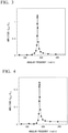
- Fig. 3 is a graph showing a ratio (vertical axis) of (amplitude U out of response voltage) / (amplitude U in of applied voltage) with respect to the frequency (horizontal axis) of the AC voltage (that is, applied voltage). It can be seen that the resonance shear curve of the upper unit 10 is measured.
- a sinusoidal AC voltage was applied to the piezoelectric element 15 while changing the frequency of the AC voltage in air, and the response voltage from the strain gauge 19 due to the vibration of the upper unit 10 was measured.
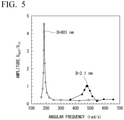
- Fig. 4 is a graph showing a ratio (vertical axis) of (amplitude U out of response voltage) / (amplitude U in of applied voltage) with respect to the frequency (horizontal axis) of the AC voltage (that is, applied voltage). It can be seen that the resonance shear curve of the upper unit 10 is measured.
- mica modified with dimethyldioctadecylammonium (DODA) was attached to the upper disk substrate 16 and the lower disk substrate 14, and pure water was inserted between the surfaces between the upper disk substrate 16 and the lower disk substrate 14.
- DODA dimethyldioctadecylammonium
- FIG. 5 is a graph showing a ratio (vertical axis) of (amplitude U out of response voltage) / (amplitude U in of applied voltage) with respect to frequency (horizontal axis) of the AC voltage (that is, applied voltage), and the measurement was performed using the resonance shear measurement device 1 having the strain gauge 19 as the displacement measurement means.
- the inter-surface distance (D) is 801 nm, the viscosity of the liquid sample suppresses the vibrating movement, and the amplitude is smaller than in the case of air. That is, a peak intensity of the resonance shear curve decreases.
- the inter-surface distance (D) is 2.1 nm
- water is excluded and DODA molecules come into direct contact with each other to cause friction, and thus, the peak frequency of the resonance shear curve shifts to a high frequency side.
- the resonance shear measurement device of the present invention can be used for applications such as viscoelasticity measurement, lubricity measurement, and friction measurement of liquid samples and liquid crystal samples, and viscoelasticity measurement of a resin.
Landscapes
- Physics & Mathematics (AREA)
- General Health & Medical Sciences (AREA)
- Life Sciences & Earth Sciences (AREA)
- Chemical & Material Sciences (AREA)
- Analytical Chemistry (AREA)
- Biochemistry (AREA)
- Health & Medical Sciences (AREA)
- General Physics & Mathematics (AREA)
- Immunology (AREA)
- Pathology (AREA)
- Acoustics & Sound (AREA)
- Investigating Strength Of Materials By Application Of Mechanical Stress (AREA)
- Measurement Of Mechanical Vibrations Or Ultrasonic Waves (AREA)
Abstract
Description
- The present invention relates to a resonance shear measurement device.
- The inventor of the present application has developed and proposed a resonance shear measurement method of measuring the resonance shear curve of a vibration system by vibrating one surface fixed to a spring in a sinusoidal manner and sweeping a frequency (
Patent Documents -
Fig. 6 is a schematic configuration diagram showing a resonance portion of a resonance shear measurement device of the related art (Non-Patent Document 1). A resonanceshear measurement device 3 shown inFig. 6 includes anupper unit 10 having apiezoelectric element 15, anupper disk substrate 16, and aspring 17, and alower unit 11 having alower disk substrate 14, and a film-shapedsample insertion portion 21 is formed between a lower surface of theupper disk substrate 16 and an upper surface of thelower disk substrate 14. Thepiezoelectric element 15 and theupper disk substrate 16 are vibratably connected to afixed apparatus 30 via thespring 17. By inserting a sample such as a solid, liquid, or liquid crystal into thesample insertion portion 21 and applying an AC voltage to thepiezoelectric element 15 while changing a frequency of the AC voltage, the shear deformation to the sample between solid surfaces is induced. By applying a sinusoidal AC voltage to thepiezoelectric element 15 in accordance with a frequency range including a resonance frequency of theupper unit 10, from a response voltage of thecapacitance probe 20, a vibration of theupper unit 10, that is, a horizontal displacement of thespring 17 is measured in a non-contact manner to measure a resonance shear curve. Accordingly, a viscoelastic term and friction/lubrication characteristics of the sample between the solid surfaces can be accurately measured. -
- [Patent Document 1]
Japanese Patent No. 4615568 - [Patent Document 2]
Japanese Patent No. 6330212 - [Non Patent Document 1]
Shogo Shibasaki, et al. 5, " Resonance Shear Measurement on Lubrication Properties of Engine Oils: Effects of Additives ", Tribologist, February 6, 2018, Vol. 63, No. 4, p284-293 - However, in the resonance
shear measurement device 3 of the related art in which acapacitance probe 20 measures a horizontal displacement of aspring 17, there is a disadvantage that thecapacitance probe 20 should be installed with an accurate distance between thecapacitance probe 20 and thespring 17, and the distance should be controlled with high precision. In addition, thecapacitance probe 20 capable of measuring displacement at a nanometer level is expensive. Further, in order to measure a volatile sample or control a pressure in the apparatus, it is necessary to provide a large closed unit or a control unit including thecapacitance probe 20, which is difficult. - Therefore, an object of the present invention is to provide a resonance shear measurement device capable of easily measuring a resonance shear behavior, compactly and easily providing a closed unit, and reducing a manufacturing cost.
- The present invention has the following configuration.
- [1] A resonance shear measurement device including: an upper unit having a piezoelectric element, an upper disk substrate, and a spring; and a lower unit having a lower disk substrate, in which a sample insertion portion is formed between a lower surface of the upper disk substrate and an upper surface of the lower disk substrate, the piezoelectric element and the upper disk substrate are vibratably connected to a fixed apparatus via the spring, a strain gauge is attached to the spring, and a response voltage at the resonance from the strain gauge due to a vibration of the upper unit is measured by applying an AC voltage to the piezoelectric element while changing a frequency of the AC voltage.
- [2] The resonance shear measurement device according to [1], further including an information processing unit electrically connected to the piezoelectric element, in which the strain gauge is electrically connected to the information processing unit, and the information processing unit measures the response voltage at the resonance from the strain gauge due to the vibration of the upper unit by applying the AC voltage to the piezoelectric element while changing the frequency of the AC voltage.
- [3] The resonance shear measurement device according to [1] or [2], in which viscoelasticity of a sample inserted into the sample insertion portion is measured based on an amplitude of the AC voltage at the resonance and an amplitude of the response voltage at the resonance.
- [4] The resonance shear measurement device [3], in which the viscoelasticity of the sample inserted into the sample insertion portion is obtained by a physical model analysis based on a resonance shear curve obtained from the amplitude of the AC voltage and the amplitude of the response voltage with respect to the frequency.
- The resonance shear measurement device of the present invention can easily measure a resonance shear behavior, can easily provide a closed unit compactly, and can reduce a manufacturing cost.
-
-
Fig. 1 is a schematic configuration diagram showing a resonanceshear measurement device 1 according to an embodiment of the present invention. -
Fig. 2 is a schematic view showing a physical model used for analysis of a resonance shear curve of the resonanceshear measurement device 1 shown inFig. 1 . -
Fig. 3 is a graph showing a ratio (vertical axis) of (amplitude Uout of response voltage) / (amplitude Uin of applied voltage) with respect to a frequency (horizontal axis) of an AC voltage (that is, applied voltage) and a measurement is performed using a resonanceshear measurement device 3 having acapacitance probe 20 as displacement measurement means. -
Fig. 4 is a graph showing a ratio (vertical axis) of (amplitude Uout of response voltage) / (amplitude Uin of applied voltage) with respect to the frequency (horizontal axis) of the AC voltage (that is, applied voltage) and a measurement is performed using a resonanceshear measurement device 2 having astrain gauge 19 as the displacement measurement means. -
Fig. 5 is a graph showing ratio (vertical axis) of (amplitude Uout of response voltage) / (amplitude Uin of applied voltage) with respect to the frequency (horizontal axis) of the AC voltage (that is, applied voltage) for water between surfactant-modified mica surfaces. The measurement is performed using a resonanceshear measurement device 1 having thestrain gauge 19 as the displacement measurement means. -
Fig. 6 is a schematic configuration diagram showing the resonanceshear measurement device 3 of the related art. - Hereinafter, a resonance shear measurement device according to an embodiment of the present invention will be described with reference to the drawings.
- In addition, in the drawings used in the following description, in order to make it easy to understand features of the present invention, a main portion may be enlarged for convenience, and a dimensional ratio or the like of each component is not always the same as the actual one.
-
Fig. 1 is a schematic configuration diagram showing a resonanceshear measurement device 1 according to the embodiment of the present invention. - The resonance
shear measurement device 1 of the present embodiment includes anupper unit 10 having apiezoelectric element 15, anupper disk holder 13, anupper disk substrate 16, and aspring 17, and alower unit 11 having alower disk substrate 14 and alower disk holder 12. Asample insertion portion 21 is formed between a lower surface of theupper disk substrate 16 and an upper surface of thelower disk substrate 14, thepiezoelectric element 15, theupper disk holder 13, and theupper disk substrate 16 are vibratably connected to afixed apparatus 30 via aspring 17, and astrain gauge 19 is attached to thespring 17. - By applying a sinusoidal AC voltage to the
piezoelectric element 15 in accordance with a frequency range including a resonance frequency of theupper unit 10 while changing a frequency of the AC voltage, a response voltage at the resonance from thestrain gauge 19 due to a vibration of theupper unit 10 is measured. As a result, a resonance shear curve of theupper unit 10 can be obtained. - In the resonance
shear measurement device 1, thestrain gauge 19 is attached to the plate-shaped spring 17. Accordingly, unlike acapacitance probe 20 of the resonanceshear measurement device 3 of the related art that measures a horizontal displacement of thespring 17, it is not necessary to install thecapacitance probe 20 and thespring 17 at a precise distance, and a sensor unit including thestrain gauge 19 can be compactly accommodated. Since the upper unit and the lower unit are installed in a sealed container and thestrain gauge 19 is attached to thespring 17, the closed unit can be easily and compactly installed, and it is possible to control a pressure in the device. A manufacturing cost can be reduced by using aninexpensive strain gauge 19, and a resonance shear behavior when theupper unit 10 is vibrated can be measured more easily. - The sample insertion portion refers to a space between the lower surface of the
upper disk substrate 16 and the upper surface of thelower disk substrate 14 into which a sample can be inserted. - The
spring 17 suspends thepiezoelectric element 15 and theupper disk substrate 16 from thefixed apparatus 30. Thespring 17 is a pair of vertically provided plate-shaped springs capable of vibrating thepiezoelectric element 15 and theupper disk substrate 16 in a horizontal direction, and is disposed substantially perpendicular to both surfaces of the film-shapedsample insertion portion 21, that is, the lower surface of theupper disk substrate 16 and the upper surface of thelower disk substrate 14. - In general, a spring constant of the
spring 17 is about 1000 N/m, but is appropriately set according to an amplitude of the vibration of theupper unit 10 and properties of a sample to be measured and is not limited thereto. - The lower surface of the
upper disk substrate 16 and the upper surface of thelower disk substrate 14 come into direct contact with a measurement sample. In this embodiment, a mica sheet having a thickness of about 3 µm is used on the lower surface side of theupper disk substrate 16 and the upper surface side of thelower disk substrate 14. A spherical surface, a flat surface, a cylindrical surface, or the like is used for the lower surface of theupper disk substrate 16 and the upper surface of thelower disk substrate 14. Theupper disk substrate 16 and thelower disk substrate 14 may be flat plates, but it is not always easy to install the flat plates in parallel. In the resonanceshear measurement device 1 of the present embodiment, for ease of attachment, a combination is selected in which the lower surface of theupper disk substrate 16 and the upper surface of thelower disk substrate 14 are side surfaces of a cylinder, and two semi-cylinders are disposed orthogonally to each other. - Various materials such as metal, ceramics, and polymers can be used on the lower surface side of the
upper disk substrate 16 and the upper surface side of thelower disk substrate 14, and are not limited to mica. Further, in the resonanceshear measurement device 1 of the present embodiment, a cleaved mica sheet is attached to a semi-cylindrical quartz lens (curvature radius R = 20 mm) with an epoxy resin to form theupper disk substrate 16 and thelower disk substrate 14, and two semi-cylinders of theupper disk substrate 16 and thelower disk substrate 14 are disposed orthogonally to each other. A spherical surface, a flat surface, a cylindrical surface, or the like is used for the lower surface of theupper disk substrate 16 and the upper surface of thelower disk substrate 14. Theupper disk substrate 16 and thelower disk substrate 14 may be flat plates, but it is not always easy to install the flat plates in parallel. From the viewpoint of ease of attachment, a combination in which the lower surface of theupper disk substrate 16 is a spherical surface and the upper surface of thelower disk substrate 14 is a flat surface is selected. Further, from the viewpoint that accurate measurement can be easily performed, it is preferable that two semi-cylinders are disposed orthogonally to each other as theupper disk substrate 16 and thelower disk substrate 14. - The
piezoelectric element 15 is a piezoelectric element constituted by a four-sectored piezo tube in which an outer electrode is divided into four, and can vibrate theupper unit 10 having theupper disk substrate 16 right and left by applying a voltage having an appropriate amplitude and frequency to an opposing electrode and an inner electrode. In this case, a trace sample such as a solid, a liquid, or a liquid crystal is interposed in thesample insertion portion 21, and a sinusoidal AC voltage is applied to thepiezoelectric element 15 in accordance with the peripheral frequency including the resonance frequency of theupper unit 10. Accordingly, the trace sample is displaced and deformed, theupper unit 10 is vibrated right and left, and a resonance shear curve is obtained by measuring the magnitude of this amplitude with thestrain gauge 19 attached to thespring 17 by changing the frequency of the AC voltage (that is, the applied voltage). - The
sample insertion portion 21 is the space interposed between the lower surface of theupper disk substrate 16 and the upper surface of thelower disk substrate 14, and has a substantial film shape. An inter-surface distance between the lower surface of theupper disk substrate 16 and the upper surface of thelower disk substrate 14 can be appropriately set, for example, in the range of 0 nm to 2 mm according to the purpose of the resonance shear measurement. The inter-surface distance between the surfaces is defined as a distance between the closest portions of the upper and lower surfaces between a plane and a spherical surface and semi-cylindrical surfaces orthogonal to each other. - For the purpose of evaluating lubricity of a liquid between solid surfaces, an inter-surface distance between the lower surface of the
upper disk substrate 16 and the upper surface of thelower disk substrate 14 is, for example, in a range of 0.1 nm to 100 nm, preferably 0.1 nm to 60 nm, and more preferably 0.1 nm to 40 nm. - It is preferable that the inter-surface distance between the lower surface of the
upper disk substrate 16 and the upper surface of thelower disk substrate 14 can be finely adjusted in a state where the sample is interposed thesample insertion portion 21. It is preferable that the inter-surface distance between the lower surface of theupper disk substrate 16 and the upper surface of thelower disk substrate 14 can be set to 0 nm, that is, in a contact state for the control test. - For the purpose of measuring viscoelasticity of a liquid sample, an inter-surface distance between the lower surface of the
upper disk substrate 16 and the upper surface of thelower disk substrate 14 is, for example, in a range of 20 nm to 2 mm, preferably 50 nm to 1000 µm, and more preferably 100 nm to 500 µm. Also in this case, it is preferable that the inter-surface distance between the lower surface of theupper disk substrate 16 and the upper surface of thelower disk substrate 14 can be set to 0 nm, that is, in a contact state for the control test. - A required sample amount can be reduced by narrowing the inter-surface distance between the lower surface of the
upper disk substrate 16 and the upper surface of thelower disk substrate 14. For example, a typical required sample amount of a commercially available viscometer of the related art is several mL, and even a viscometer capable of measuring a small amount is at least 100 µL. However, in the resonanceshear measurement device 1 of the present embodiment, the required sample amount is 20 µL or more. - The resonance
shear measurement device 1 further includes aninformation processing unit 40 electrically connected to thepiezoelectric element 15. Thestrain gauge 19 is also electrically connected to theinformation processing unit 40. Theinformation processing unit 40 is configured to measure the response voltage at the resonance from thestrain gauge 19 due to the vibration of theupper unit 10 by applying a sinusoidal AC voltage to thepiezoelectric element 15 while changing the frequency of the AC voltage. - The
information processing unit 40 as driving means of thepiezoelectric element 15 applies the AC voltage to thepiezoelectric element 15 and detects a response voltage from thestrain gauge 19. Theinformation processing unit 40 can detect an amplitude Uout of the response voltage together with an amplitude Uin of the AC voltage (that is, applied voltage). It is also possible to obtain the resonance shear curve by Fourier transforming an attenuation curve of the amplitude Uout. By measuring the amplitude Uout of the response voltage together with a change in the inter-surface distance, the attenuation curve of the amplitude Uout can be Fourier transformed to obtain the resonance shear curve. - The resonance
shear measurement device 1 can measure the viscoelastic term of the sample inserted into thesample insertion portion 21 based on the amplitude of the AC voltage (that is, the applied voltage) at the resonance and the amplitude of the response voltage at the resonance, as shown in Examples described later. - The resonance
shear measurement device 1 can measure the viscoelastic term of the sample inserted into thesample insertion portion 21 based on the resonance shear curve obtained from the amplitude of the AC voltage (that is, the applied voltage) and the amplitude of the response voltage with respect to the frequency, as shown in Examples described later. - In the
lower unit 11 of the resonanceshear measurement device 1, thelower disk substrate 14 is fixed to thelower disk holder 12, and thelower disk holder 12 is connected to ahorizontal spring 22. Thehorizontal spring 22 acts as a cantilever for measuring a normal force, and has a configuration capable of controlling a vertical displacement of thelower disk substrate 14. - That is, the
lower unit 11 is connected to amicro drive system 23 including a pulse motor and a differential spring via twohorizontal springs 22, and an inter-surface distance (D) between the lower surface of theupper disk substrate 16 and the upper surface of thelower disk substrate 14 can be controlled with a resolution of 1 nm or less. - Further, in the resonance
shear measurement device 1, the inter-surface distance (D) can be determined with a resolution of 0.1 nm from an analysis of Fringes of Equal Chromatic Order (FECO) caused by multiple reflections of white light vertically incident on the surface between silver-deposited surfaces. Bending of thehorizontal spring 22 is determined as the difference (ΔD) between a "driving distance" by the pulse motor and the "change in the inter-surface distance", and a load (L) is obtained by multiplying a spring constant (K) of the horizontal spring 22 (L = KΔD). In addition to this, ΔD and L can also be determined by using a twin-path method, which is a distance determination method by an interferometer using reflected light from the lower surface of the lower unit. - As the
upper unit 10, theupper disk substrate 16 is fixed to thepiezoelectric element 15 constituted by a four-sectored piezo tube via theupper disk holder 13. Further, theupper disk substrate 16 and theupper disk holder 13 are connected to the twosprings 17 via thepiezoelectric element 15. Antiphase sinusoidal waveform voltages (amplitude Uin, frequency f) are applied to two opposing electrodes of the four-sectored piezo tube to vibrate the lower surface of theupper disk substrate 16 in the horizontal direction, and thus, a vibration displacement (Δx) of a tip of thespring 17 can be measured as the output voltage Uout by thestrain gauge 19. An angular frequency co (= 2πf) is swept and the output voltage Uout is measured to obtain the resonance shear curve (Uout/Uin vs ω). In the air, in a state where the lower surface of theupper disk substrate 16 and the upper surface of thelower disk substrate 14 are separated from each other (separation in air, Air Separation (AS)), a resonance peak is observed at the frequency (ωAS) determined by a mass (mi) of theupper unit 10 and a spring constant (ki). - In a non-slip state (Solid Contact (SC)) in which the lower surface of the
upper disk substrate 16 and the upper surface of thelower disk substrate 14 are in contact with each other in air, a mass (m2) of thelower unit 11 including thelower disk substrate 14, thelower disk holder 12 and thehorizontal spring 22 and a lateral spring constant (k3) of thehorizontal spring 22 are added to theupper unit 10, and the resonance peak is shifted to a higher frequency (ωsc). The AS peak and the SC peak each correspond to the non-friction state and the non-slip state. With reference to these peaks, the characteristics of the liquid sample can be evaluated by the amplitude and frequency of the resonance peak measured in a state where the liquid sample is interposed between thesample insertion portion 21 between the lower surface of theupper disk substrate 16 and the upper surface of thelower disk substrate 14. Typically, the AS peak frequency ωAS is observed around 195 rad/s (31 Hz), and the SC peak frequency ωsc is observed around 350 rad / s (56 Hz). However, since the resonance peak may change for each setting, the AS peak and the SC peak are measured for each setting. -
Fig. 2 is a schematic view showing a physical model of the resonanceshear measurement device 1 shown inFig. 1 used for analyzing the resonance shear curve. A viscosity term b1, an elasticity term k1, and an effective mass m1 are considered as parameters of theupper unit 10. A viscosity term b2 and an elasticity term k2 are considered as a sample liquid portion. A viscosity term b3, an elasticity term k3, and an effective mass m2 are considered as parameters of thelower unit 11. Using these parameters, equations of motion of the lower surface of theupper disk substrate 16 and the upper surface of thelower disk substrate 14 can be expressed as follows.

- Here, x1 is a horizontal displacement of the lower surface of the
upper disk substrate 16, x2 is a horizontal displacement of the upper surface of thelower disk substrate 14, and α is measured by x1 and thestrain gauge 19. A parameter (αd) relates x1 to xmeasured, a displacement of the plate-shapedspring 17 provided in the vertical direction, to be x1=αxmeasured). , Fexp (iωt) represents an external force from thepiezoelectric element 15. By solving simultaneous differential equations of Expressions (1) and (2) with stationary solutions of x1 and x2 as x1 = X1exp (iωt+ϕ1) and x2 = X2exp (iωt + ϕ2), amplitudes (X1, X2) and an analytical solution of a phase term (ϕ1, ϕ2) can be obtained. From the solution of X1, a theoretical formula of the resonance shear curve (Uout/Uinvs ω) is expressed as follows.
- Here, B1 = b1/α + b2, B2 = b2 + b3, K1 = k1/α + k2, K2 = k2 + k3. Here, α is fixed to α = 1 obtained by actual measurement. For m1, a measured value of the mass of the upper unit is used. By setting b2, k2, b3, k3, and m2 in Expression (3) to zero, the resonance shear curve of the air separation (AS) is fitted, and the parameters k1 and b1 of the
upper unit 10 are determined. - Further, the resonance shear curve of the solid contact (SC) is fitted by Expression in which the term of the parameter (k2, b2) of the sample portion in Expression (3) is eliminated by setting x1 = x2, and the parameters b3 and k3 of the
lower unit 11 are determined. The parameters (b2, k2) of the sample portion are determined by fitting the resonance shear curve measured in the state where the sample is interposed between thesample insertion portion 21 between the lower surface of theupper disk substrate 16 and the upper surface of thelower disk substrate 14. A device constant C can be determined by fitting the resonance shear curves of thelower unit 11's non-contributory air separation (AS) and thelower unit 11's contributory solid contact (SC). - A relationship between the viscosity parameter b2 (Ns/m) and the viscosity η (N/m2·s) is represented by b2 = ηA/D (A: shear area, D: inter-surface distance between lower surface of
upper disk substrate 16 and upper surface of lower disk substrate 14). - Hereinafter, the present invention will be described in more detail with reference to Examples or the like, but the scope of the present invention is not limited to the Examples or the like.
- Using a resonance
shear measurement device 3 of the related art shown inFig. 6 including acapacitance probe 20 as displacement measurement means, a sinusoidal AC voltage was applied to thepiezoelectric element 15 while changing the frequency of the AC voltage in air, and the response voltage from thecapacitance probe 20 due to the vibration of theupper unit 10 was measured.Fig. 3 is a graph showing a ratio (vertical axis) of (amplitude Uout of response voltage) / (amplitude Uin of applied voltage) with respect to the frequency (horizontal axis) of the AC voltage (that is, applied voltage). It can be seen that the resonance shear curve of theupper unit 10 is measured. - Using the resonance
shear measurement device 1 of the present embodiment shown inFig. 1 including thestrain gauge 19 as the displacement measurement means, a sinusoidal AC voltage was applied to thepiezoelectric element 15 while changing the frequency of the AC voltage in air, and the response voltage from thestrain gauge 19 due to the vibration of theupper unit 10 was measured.Fig. 4 is a graph showing a ratio (vertical axis) of (amplitude Uout of response voltage) / (amplitude Uin of applied voltage) with respect to the frequency (horizontal axis) of the AC voltage (that is, applied voltage). It can be seen that the resonance shear curve of theupper unit 10 is measured. - In the resonance
shear measurement device 1 of the present embodiment, mica modified with dimethyldioctadecylammonium (DODA) was attached to theupper disk substrate 16 and thelower disk substrate 14, and pure water was inserted between the surfaces between theupper disk substrate 16 and thelower disk substrate 14. The response voltage from thestrain gauge 19 due to the vibration of theupper unit 10 was measured by applying a sinusoidal AC voltage to thepiezoelectric element 15 while changing the frequency of the AC voltage in a state where the pure water was interposed in thesample insertion portion 21.Fig. 5 is a graph showing a ratio (vertical axis) of (amplitude Uout of response voltage) / (amplitude Uin of applied voltage) with respect to frequency (horizontal axis) of the AC voltage (that is, applied voltage), and the measurement was performed using the resonanceshear measurement device 1 having thestrain gauge 19 as the displacement measurement means. When the inter-surface distance (D) is 801 nm, the viscosity of the liquid sample suppresses the vibrating movement, and the amplitude is smaller than in the case of air. That is, a peak intensity of the resonance shear curve decreases. Further, when the inter-surface distance (D) is 2.1 nm, water is excluded and DODA molecules come into direct contact with each other to cause friction, and thus, the peak frequency of the resonance shear curve shifts to a high frequency side. By changing the inter-surface distance (D) and the load (L) in this way and comparing the peak frequency and peak intensity of the resonance shear curve, changes in the viscoelasticity and friction of the liquid between the surfaces can be measured. - The resonance shear measurement device of the present invention can be used for applications such as viscoelasticity measurement, lubricity measurement, and friction measurement of liquid samples and liquid crystal samples, and viscoelasticity measurement of a resin.
-
- 1, 3:
- Resonance shear measurement device
- 10:
- Upper unit
- 11:
- Lower unit
- 12:
- Lower disk holder
- 13:
- Upper disk holder
- 14:
- Lower disk substrate
- 15:
- Piezoelectric element
- 16:
- Upper disk substrate
- 17:
- Spring
- 18:
- Electric cable
- 19:
- Strain gauge
- 20:
- Capacitance probe
- 21:
- Sample insertion portion
- 22:
- Horizontal spring
- 23:
- Micro drive system
- 30:
- Fixed apparatus
- 40:
- Information processing unit
Claims (4)
- A resonance shear measurement device comprising:an upper unit having a piezoelectric element, an upper disk substrate, and a spring; anda lower unit having a lower disk substrate,wherein a sample insertion portion is formed between a lower surface of the upper disk substrate and an upper surface of the lower disk substrate,the piezoelectric element and the upper disk substrate are vibratably connected to a fixed apparatus via the spring,a strain gauge is attached to the spring, anda response voltage at the resonance is measured from the strain gauge due to a vibration of the upper unit by applying an AC voltage to the piezoelectric element while changing a frequency of the AC voltage.
- The resonance shear measurement device according to Claim 1, further comprising an information processing unit electrically connected to the piezoelectric element,
wherein the strain gauge is electrically connected to the information processing unit, and the information processing unit measures the response voltage at the resonance from the strain gauge due to the vibration of the upper unit by applying the AC voltage to the piezoelectric element while changing the frequency of the AC voltage. - The resonance shear measurement device according to Claim 1 or 2, wherein viscoelasticity of a sample inserted into the sample insertion portion is measured based on an amplitude of the AC voltage at the resonance and an amplitude of the response voltage at the resonance.
- The resonance shear measurement device according to Claim 3,
wherein the viscoelasticity of the sample inserted into the sample insertion portion is measured by a physical model analysis based on a resonance shear curve obtained from the amplitude of the AC voltage and the amplitude of the response voltage with respect to the frequency.
Applications Claiming Priority (1)
| Application Number | Priority Date | Filing Date | Title |
|---|---|---|---|
| PCT/JP2019/013845 WO2020194734A1 (en) | 2019-03-28 | 2019-03-28 | Resonance shear measurement device |
Publications (2)
| Publication Number | Publication Date |
|---|---|
| EP3951350A1 true EP3951350A1 (en) | 2022-02-09 |
| EP3951350A4 EP3951350A4 (en) | 2022-11-16 |
Family
ID=72611771
Family Applications (1)
| Application Number | Title | Priority Date | Filing Date |
|---|---|---|---|
| EP19921673.0A Withdrawn EP3951350A4 (en) | 2019-03-28 | 2019-03-28 | RESONANCE SHEAR MEASUREMENT DEVICE |
Country Status (5)
| Country | Link |
|---|---|
| US (1) | US11927517B2 (en) |
| EP (1) | EP3951350A4 (en) |
| JP (1) | JP7244958B2 (en) |
| CN (1) | CN113614508A (en) |
| WO (1) | WO2020194734A1 (en) |
Families Citing this family (2)
| Publication number | Priority date | Publication date | Assignee | Title |
|---|---|---|---|---|
| JP7477171B2 (en) * | 2021-02-09 | 2024-05-01 | 国立大学法人東北大学 | Resonance shear measuring device and method of using same, and viscometer and method of using same |
| JP7786678B2 (en) * | 2022-03-30 | 2025-12-16 | 日新電機株式会社 | Specimen deterioration detection device and detection method |
Family Cites Families (14)
| Publication number | Priority date | Publication date | Assignee | Title |
|---|---|---|---|---|
| JPS53124450U (en) * | 1977-03-11 | 1978-10-03 | ||
| JPS5589056A (en) | 1978-12-20 | 1980-07-05 | Yoshino Kogyosho Co Ltd | Twooaxissextended bottle |
| JPH0293302A (en) * | 1988-09-30 | 1990-04-04 | Toshiba Corp | Displacement meter |
| US5094100A (en) * | 1990-07-11 | 1992-03-10 | Dealy John M | Method and apparatus for measuring shear stress |
| JP3032152B2 (en) * | 1996-03-25 | 2000-04-10 | 科学技術振興事業団 | Precise shear stress measuring device |
| US5705738A (en) * | 1997-01-16 | 1998-01-06 | Japan Science And Technology Corporation | Precise shear-stress measurement apparatus |
| CN1177212C (en) * | 2001-09-19 | 2004-11-24 | 中国科学院化学研究所 | Shear Force Detector |
| JP2004294218A (en) * | 2003-03-26 | 2004-10-21 | Kansai Tlo Kk | Measuring method of physical property value and scanning probe microscope |
| EP1942331A4 (en) * | 2005-09-28 | 2015-09-02 | Japan Science & Tech Agency | SHEAR MEASUREMENT METHOD AND ITS DEVICE |
| JP4845047B2 (en) * | 2007-08-31 | 2011-12-28 | 独立行政法人産業技術総合研究所 | Viscometer |
| US8939041B2 (en) | 2011-02-10 | 2015-01-27 | Hysitron, Inc. | Nanomechanical testing system |
| JP6065599B2 (en) * | 2013-01-17 | 2017-01-25 | 大日本印刷株式会社 | Multi-faceted body of lead frame, multi-faceted body of lead frame with resin, multi-faceted body of optical semiconductor device |
| EP3039400B1 (en) | 2013-08-27 | 2021-10-06 | Rheolution Inc. | System and method for the measurements of visoelastic parameters in soft materials |
| JP6330212B2 (en) | 2013-10-10 | 2018-05-30 | 和枝 栗原 | Heating method of micro sample |
-
2019
- 2019-03-28 CN CN201980094485.6A patent/CN113614508A/en active Pending
- 2019-03-28 US US17/593,222 patent/US11927517B2/en active Active
- 2019-03-28 WO PCT/JP2019/013845 patent/WO2020194734A1/en not_active Ceased
- 2019-03-28 EP EP19921673.0A patent/EP3951350A4/en not_active Withdrawn
- 2019-03-28 JP JP2021508656A patent/JP7244958B2/en active Active
Also Published As
| Publication number | Publication date |
|---|---|
| US20220155202A1 (en) | 2022-05-19 |
| JP7244958B2 (en) | 2023-03-23 |
| CN113614508A (en) | 2021-11-05 |
| JPWO2020194734A1 (en) | 2021-10-14 |
| WO2020194734A1 (en) | 2020-10-01 |
| US11927517B2 (en) | 2024-03-12 |
| EP3951350A4 (en) | 2022-11-16 |
Similar Documents
| Publication | Publication Date | Title |
|---|---|---|
| Munz | Force calibration in lateral force microscopy: a review of the experimental methods | |
| Mahaffy et al. | Scanning probe-based frequency-dependent microrheology of polymer gels and biological cells | |
| EP0801734B1 (en) | Complex viscosity and complex modulus measurement device and method | |
| WO2013111608A1 (en) | Viscoelasticity measurement method and viscoelasticity measurement device | |
| EP0501976B1 (en) | Rheometer | |
| CN110455656A (en) | Micromechanical comb tooth structure and detection method for precision action/sensing dual-mode integration | |
| KR20150060908A (en) | Method and device for measuring fluid body physical properties | |
| US11927517B2 (en) | Resonance shear measurement device | |
| CN104865410A (en) | Conductor surface potential measuring instrument based on static controlled twist pendulum | |
| CN102374967B (en) | Shear measuring method and its device | |
| CN1288451C (en) | Detection method for resonance frequency of resonant type piezoelectric microsensor | |
| JP7477171B2 (en) | Resonance shear measuring device and method of using same, and viscometer and method of using same | |
| KR101039328B1 (en) | Self Vibration Measurement System and Method for Measuring Rheological Properties of Fluids | |
| JP7318996B2 (en) | Resonance shear measurement device | |
| JP3032152B2 (en) | Precise shear stress measuring device | |
| US5705738A (en) | Precise shear-stress measurement apparatus | |
| US11761872B2 (en) | Viscometer and method for measuring viscosity | |
| JP2009204318A (en) | Vibration-type viscometer | |
| CN102706924B (en) | Device for realizing second-order resonant excitation of micro-cantilever probe | |
| JP7049465B2 (en) | Two-dimensional nanoindentation device and method | |
| Schilowitz et al. | Measuring hydrocarbon viscosity with oscillating microcantilevers | |
| RU2731039C1 (en) | Device for measuring surface relief parameters and mechanical properties of materials | |
| CN101393008A (en) | PVDF-based tap-type high-sensitivity SPM probe and measurement method | |
| Riesch | Micromachined viscosity sensors | |
| CN1664551A (en) | A Measuring Method of Dynamic Bending Moment |
Legal Events
| Date | Code | Title | Description |
|---|---|---|---|
| STAA | Information on the status of an ep patent application or granted ep patent |
Free format text: STATUS: THE INTERNATIONAL PUBLICATION HAS BEEN MADE |
|
| PUAI | Public reference made under article 153(3) epc to a published international application that has entered the european phase |
Free format text: ORIGINAL CODE: 0009012 |
|
| STAA | Information on the status of an ep patent application or granted ep patent |
Free format text: STATUS: REQUEST FOR EXAMINATION WAS MADE |
|
| 17P | Request for examination filed |
Effective date: 20210914 |
|
| AK | Designated contracting states |
Kind code of ref document: A1 Designated state(s): AL AT BE BG CH CY CZ DE DK EE ES FI FR GB GR HR HU IE IS IT LI LT LU LV MC MK MT NL NO PL PT RO RS SE SI SK SM TR |
|
| DAV | Request for validation of the european patent (deleted) | ||
| DAX | Request for extension of the european patent (deleted) | ||
| A4 | Supplementary search report drawn up and despatched |
Effective date: 20221014 |
|
| RIC1 | Information provided on ipc code assigned before grant |
Ipc: G01N 11/00 20060101AFI20221010BHEP |
|
| STAA | Information on the status of an ep patent application or granted ep patent |
Free format text: STATUS: THE APPLICATION IS DEEMED TO BE WITHDRAWN |
|
| 18D | Application deemed to be withdrawn |
Effective date: 20230513 |