EP3951332A1 - Weight estimation system - Google Patents
Weight estimation system Download PDFInfo
- Publication number
- EP3951332A1 EP3951332A1 EP20782691.8A EP20782691A EP3951332A1 EP 3951332 A1 EP3951332 A1 EP 3951332A1 EP 20782691 A EP20782691 A EP 20782691A EP 3951332 A1 EP3951332 A1 EP 3951332A1
- Authority
- EP
- European Patent Office
- Prior art keywords
- loading
- vehicle
- center
- gravity position
- transport vehicle
- Prior art date
- Legal status (The legal status is an assumption and is not a legal conclusion. Google has not performed a legal analysis and makes no representation as to the accuracy of the status listed.)
- Pending
Links
- 230000005484 gravity Effects 0.000 claims description 37
- 238000013507 mapping Methods 0.000 description 9
- 238000001514 detection method Methods 0.000 description 6
- 230000001133 acceleration Effects 0.000 description 3
- 239000003550 marker Substances 0.000 description 3
- 238000005259 measurement Methods 0.000 description 3
- 238000000034 method Methods 0.000 description 2
- 238000012545 processing Methods 0.000 description 2
- 238000004891 communication Methods 0.000 description 1
- 230000002596 correlated effect Effects 0.000 description 1
- 230000000694 effects Effects 0.000 description 1
- 238000005516 engineering process Methods 0.000 description 1
- 230000006870 function Effects 0.000 description 1
- 238000003384 imaging method Methods 0.000 description 1
- 230000004807 localization Effects 0.000 description 1
Images


Classifications
-
- B—PERFORMING OPERATIONS; TRANSPORTING
- B60—VEHICLES IN GENERAL
- B60W—CONJOINT CONTROL OF VEHICLE SUB-UNITS OF DIFFERENT TYPE OR DIFFERENT FUNCTION; CONTROL SYSTEMS SPECIALLY ADAPTED FOR HYBRID VEHICLES; ROAD VEHICLE DRIVE CONTROL SYSTEMS FOR PURPOSES NOT RELATED TO THE CONTROL OF A PARTICULAR SUB-UNIT
- B60W40/00—Estimation or calculation of non-directly measurable driving parameters for road vehicle drive control systems not related to the control of a particular sub unit, e.g. by using mathematical models
- B60W40/12—Estimation or calculation of non-directly measurable driving parameters for road vehicle drive control systems not related to the control of a particular sub unit, e.g. by using mathematical models related to parameters of the vehicle itself, e.g. tyre models
- B60W40/13—Load or weight
-
- B—PERFORMING OPERATIONS; TRANSPORTING
- B60—VEHICLES IN GENERAL
- B60K—ARRANGEMENT OR MOUNTING OF PROPULSION UNITS OR OF TRANSMISSIONS IN VEHICLES; ARRANGEMENT OR MOUNTING OF PLURAL DIVERSE PRIME-MOVERS IN VEHICLES; AUXILIARY DRIVES FOR VEHICLES; INSTRUMENTATION OR DASHBOARDS FOR VEHICLES; ARRANGEMENTS IN CONNECTION WITH COOLING, AIR INTAKE, GAS EXHAUST OR FUEL SUPPLY OF PROPULSION UNITS IN VEHICLES
- B60K31/00—Vehicle fittings, acting on a single sub-unit only, for automatically controlling vehicle speed, i.e. preventing speed from exceeding an arbitrarily established velocity or maintaining speed at a particular velocity, as selected by the vehicle operator
-
- B—PERFORMING OPERATIONS; TRANSPORTING
- B60—VEHICLES IN GENERAL
- B60W—CONJOINT CONTROL OF VEHICLE SUB-UNITS OF DIFFERENT TYPE OR DIFFERENT FUNCTION; CONTROL SYSTEMS SPECIALLY ADAPTED FOR HYBRID VEHICLES; ROAD VEHICLE DRIVE CONTROL SYSTEMS FOR PURPOSES NOT RELATED TO THE CONTROL OF A PARTICULAR SUB-UNIT
- B60W30/00—Purposes of road vehicle drive control systems not related to the control of a particular sub-unit, e.g. of systems using conjoint control of vehicle sub-units, or advanced driver assistance systems for ensuring comfort, stability and safety or drive control systems for propelling or retarding the vehicle
- B60W30/14—Adaptive cruise control
- B60W30/143—Speed control
- B60W30/146—Speed limiting
-
- G—PHYSICS
- G01—MEASURING; TESTING
- G01G—WEIGHING
- G01G19/00—Weighing apparatus or methods adapted for special purposes not provided for in the preceding groups
- G01G19/08—Weighing apparatus or methods adapted for special purposes not provided for in the preceding groups for incorporation in vehicles
- G01G19/12—Weighing apparatus or methods adapted for special purposes not provided for in the preceding groups for incorporation in vehicles having electrical weight-sensitive devices
-
- G—PHYSICS
- G01—MEASURING; TESTING
- G01G—WEIGHING
- G01G19/00—Weighing apparatus or methods adapted for special purposes not provided for in the preceding groups
- G01G19/64—Percentage-indicating weighing apparatus, i.e. for expressing the weight as a percentage of a predetermined or initial weight
-
- G—PHYSICS
- G01—MEASURING; TESTING
- G01G—WEIGHING
- G01G23/00—Auxiliary devices for weighing apparatus
- G01G23/18—Indicating devices, e.g. for remote indication; Recording devices; Scales, e.g. graduated
- G01G23/32—Indicating the weight by optical projection means
-
- G—PHYSICS
- G01—MEASURING; TESTING
- G01G—WEIGHING
- G01G9/00—Methods of, or apparatus for, the determination of weight, not provided for in groups G01G1/00 - G01G7/00
-
- G—PHYSICS
- G01—MEASURING; TESTING
- G01M—TESTING STATIC OR DYNAMIC BALANCE OF MACHINES OR STRUCTURES; TESTING OF STRUCTURES OR APPARATUS, NOT OTHERWISE PROVIDED FOR
- G01M1/00—Testing static or dynamic balance of machines or structures
- G01M1/12—Static balancing; Determining position of centre of gravity
- G01M1/122—Determining position of centre of gravity
-
- B—PERFORMING OPERATIONS; TRANSPORTING
- B60—VEHICLES IN GENERAL
- B60W—CONJOINT CONTROL OF VEHICLE SUB-UNITS OF DIFFERENT TYPE OR DIFFERENT FUNCTION; CONTROL SYSTEMS SPECIALLY ADAPTED FOR HYBRID VEHICLES; ROAD VEHICLE DRIVE CONTROL SYSTEMS FOR PURPOSES NOT RELATED TO THE CONTROL OF A PARTICULAR SUB-UNIT
- B60W40/00—Estimation or calculation of non-directly measurable driving parameters for road vehicle drive control systems not related to the control of a particular sub unit, e.g. by using mathematical models
- B60W40/12—Estimation or calculation of non-directly measurable driving parameters for road vehicle drive control systems not related to the control of a particular sub unit, e.g. by using mathematical models related to parameters of the vehicle itself, e.g. tyre models
- B60W40/13—Load or weight
- B60W2040/1315—Location of the centre of gravity
-
- B—PERFORMING OPERATIONS; TRANSPORTING
- B60—VEHICLES IN GENERAL
- B60W—CONJOINT CONTROL OF VEHICLE SUB-UNITS OF DIFFERENT TYPE OR DIFFERENT FUNCTION; CONTROL SYSTEMS SPECIALLY ADAPTED FOR HYBRID VEHICLES; ROAD VEHICLE DRIVE CONTROL SYSTEMS FOR PURPOSES NOT RELATED TO THE CONTROL OF A PARTICULAR SUB-UNIT
- B60W2300/00—Indexing codes relating to the type of vehicle
- B60W2300/12—Trucks; Load vehicles
-
- B60W2420/408—
-
- B—PERFORMING OPERATIONS; TRANSPORTING
- B60—VEHICLES IN GENERAL
- B60W—CONJOINT CONTROL OF VEHICLE SUB-UNITS OF DIFFERENT TYPE OR DIFFERENT FUNCTION; CONTROL SYSTEMS SPECIALLY ADAPTED FOR HYBRID VEHICLES; ROAD VEHICLE DRIVE CONTROL SYSTEMS FOR PURPOSES NOT RELATED TO THE CONTROL OF A PARTICULAR SUB-UNIT
- B60W2422/00—Indexing codes relating to the special location or mounting of sensors
- B60W2422/95—Measuring the same parameter at multiple locations of the vehicle
-
- B—PERFORMING OPERATIONS; TRANSPORTING
- B60—VEHICLES IN GENERAL
- B60W—CONJOINT CONTROL OF VEHICLE SUB-UNITS OF DIFFERENT TYPE OR DIFFERENT FUNCTION; CONTROL SYSTEMS SPECIALLY ADAPTED FOR HYBRID VEHICLES; ROAD VEHICLE DRIVE CONTROL SYSTEMS FOR PURPOSES NOT RELATED TO THE CONTROL OF A PARTICULAR SUB-UNIT
- B60W2530/00—Input parameters relating to vehicle conditions or values, not covered by groups B60W2510/00 or B60W2520/00
- B60W2530/10—Weight
-
- B—PERFORMING OPERATIONS; TRANSPORTING
- B60—VEHICLES IN GENERAL
- B60W—CONJOINT CONTROL OF VEHICLE SUB-UNITS OF DIFFERENT TYPE OR DIFFERENT FUNCTION; CONTROL SYSTEMS SPECIALLY ADAPTED FOR HYBRID VEHICLES; ROAD VEHICLE DRIVE CONTROL SYSTEMS FOR PURPOSES NOT RELATED TO THE CONTROL OF A PARTICULAR SUB-UNIT
- B60W2556/00—Input parameters relating to data
- B60W2556/10—Historical data
-
- B—PERFORMING OPERATIONS; TRANSPORTING
- B60—VEHICLES IN GENERAL
- B60W—CONJOINT CONTROL OF VEHICLE SUB-UNITS OF DIFFERENT TYPE OR DIFFERENT FUNCTION; CONTROL SYSTEMS SPECIALLY ADAPTED FOR HYBRID VEHICLES; ROAD VEHICLE DRIVE CONTROL SYSTEMS FOR PURPOSES NOT RELATED TO THE CONTROL OF A PARTICULAR SUB-UNIT
- B60W2720/00—Output or target parameters relating to overall vehicle dynamics
- B60W2720/10—Longitudinal speed
- B60W2720/106—Longitudinal acceleration
Definitions
- the present disclosure relates to a weight estimation system.
- Patent Document 1 discloses an automatic guided vehicle. Such an automatic guided vehicle of Patent Document 1 is used for loading and unloading a container for a container ship and autonomously travels on a traveling route on the basis of a command of program control that performs driving control. Also, in the automatic guided vehicle of Patent Document 1, a weight of a container loaded on a vehicle is estimated on the basis of a torque of an electric motor at the time of traveling.
- the present disclosure has been made in view of the above-described problems, and an objective of the present disclosure is to estimate a weight of a load in a transport vehicle.
- a first aspect according to a weight estimation system of the present disclosure employs a weight estimation system including: a change amount calculation device which acquires a height of a loading platform before loading a vehicle and a height of the loading platform after loading the vehicle and calculates an amount of change between the heights of the loading platform between before and after the loading, and a loaded weight estimation device which estimates a loaded weight on the basis of a correlation between the amount of change and a loaded weight stored in advance.
- the above-described first aspect may include a measuring device mounted on the vehicle and which measures a height of the loading platform of the vehicle.
- the measuring device may be one of a plurality of measuring devices, the plurality of measuring devices may be provided in the vehicle, and a center of gravity position estimation device which estimates a center of gravity position on the basis of differences between the heights of the loading platform after the loading, the heights being obtained from the plurality of measuring devices may be provided.
- the above-described third aspect may include a speed limit setting device which sets a speed limit of the vehicle on the basis of the center of gravity position.
- a weight of a load in a transport vehicle can be estimated by the loaded weight estimation device.
- a driving control system S (i.e., weight estimation system) according to one embodiment of the present disclosure is a system for transporting an object to be transported (for example, a container C) to a desired location or assisting the transport thereof.
- the driving control system S of the present disclosure is a system for performing autonomous traveling of a transport vehicle transporting an object to be transported.
- the driving control system S includes a plurality of distance sensors 1 (i.e., measuring device), a change amount calculation unit 2 (i.e., change amount calculation device), a center of gravity position estimation unit 3 (i.e., center of gravity position estimation device), a loaded weight estimation unit 4 (i.e., loaded weight estimation device), a speed limit setting unit 5 (i.e., speed limit setting device), and a driving control unit 6.
- the change amount calculation unit 2, the center of gravity position estimation unit 3, the loaded weight estimation unit 4, the speed limit setting unit 5, and the driving control unit 6 are configured as one function of a computing device.
- the computing device described above is a computer configured by a central processing unit (CPU)), a memory, and the like.
- the computing device described above may be, for example, an ECU mounted on a transport vehicle.
- the change amount calculation unit 2 i.e., change amount calculation device
- the center of gravity position estimation unit 3 i.e., center of gravity position estimation device
- the loaded weight estimation unit 4 i.e., loaded weight estimation device
- the speed limit setting unit 5 i.e., speed limit setting device
- the driving control unit 6 may each be a computer configured by a central processing unit (i.e., CPU), a memory, and the like.
- two distance sensors 1 are provided to face in a front-rear direction in a traveling direction as shown in FIG. 2 , and furthermore, two distance sensors 1 are provided on a chassis disposed in a direction (i.e., left-right direction) perpendicular to the traveling direction to be separated by a predetermined distance as shown in FIG. 1 . That is, the distance sensors 1 are attached to four measurement points in total at the left, right, front, and rear of the lower part of the vehicle.
- Such a distance sensor 1 is a device that measures a distance of a loading platform N from the ground (i.e., height of the loading platform N) by scanning with a laser beam downward in a vertical direction.
- the distance sensor 1 attached on the front side in the traveling direction can scan a region including a front and rear of the transport vehicle and can also detect an obstacle.
- the distance sensor 1 may be, for example, a two-dimensional or three-dimensional laser range finder (i.e., LRF) or a two-dimensional or three-dimensional laser imaging detection and ranging (i.e., LIDAR, Light Detection and Ranging).
- the distance sensor 1 may be one to which data of a sensor used for simultaneous localization and mapping (i.e., SLAM) is applied.
- the change amount calculation unit 2 acquires a distance from the chassis of the transport vehicle to the ground from the distance sensor 1. Then, the change amount calculation unit 2 calculates a difference (i.e., amount of change) between distances in each distance sensor 1, the distances being from the chassis of the transport vehicle to the ground before and after loading.
- a difference i.e., amount of change
- the center of gravity position estimation unit 3 acquires the differences between the distances, the differences being calculated by the change amount calculation unit 2, and the distances being to the ground in the four distance sensors 1. Then, the center of gravity position estimation unit 3 estimates a center of gravity position of the transport vehicle on the basis of the differences between the distances, the distances being to the ground acquired from the four distance sensors 1. A magnitude of the difference is correlated with a magnitude of the load at the measurement point. Therefore, the center of gravity position estimation unit 3 can estimate a center of gravity position from the differences between the distances, the distances being from the ground for the measurement points in the front-rear direction and the left-right direction, by calculating a mapping of a correlation between differences between distances from the ground and a center of gravity position in advance.
- the loaded weight estimation unit 4 acquires the differences between the distances, the differences being calculated by the change amount calculation unit 2, and the distances being to the ground in the four distance sensors 1, and calculates, for example, an average value. Then, the loaded weight estimation unit 4 estimates a loaded weight on the basis of mapping data of the correlation between the loaded weight and the difference between the distances to the ground stored in advance. Further, the mapping data of the correlation between the loaded weight and the difference between the distances to the ground has a trend in which the loaded weight becomes larger as the difference between the distances to the ground becomes larger.
- the speed limit setting unit 5 stores in advance a mapping of a correlation of the center of gravity position, the loaded weight, and a speed limit that does not cause a load collapse or a rollover. Then, the speed limit setting unit 5 acquires the center of gravity position and the loaded weight from the center of gravity position estimation unit 3 and the loaded weight estimation unit 4, and sets a speed limit of the transport vehicle on the basis of the above-described mapping of the correlation of the center of gravity position, the loaded weight, and the speed limit that does not cause a load collapse or a rollover. Further, the mapping of the correlation tends to set the speed limit to be lower, for example, when the center of gravity position of the transport vehicle is biased to one location of the transport vehicle or when the loaded weight is heavy.
- the driving control unit 6 is a device that autonomously drives the transport vehicle on the basis of the estimated center of gravity position, the estimated loaded weight, and the speed limit. Further, the driving control unit 6 can autonomously drive the transport vehicle by storing driving routes in advance and using an obstacle detection system such as a camera or LIDAR.
- an obstacle detection system such as a camera or LIDAR.
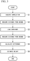
- the driving control system S acquires in advance a correlation between a difference between distances of the transport vehicle from the ground before and after loading and a loaded weight by measuring them beforehand (step S1).
- the driving control system S In estimating a loaded weight in an actual transport vehicle, the driving control system S first measures a distance from the ground before loading using the distance sensor 1 (step S2), and then loads the container C on the transport vehicle (step S3).
- the driving control system S measures a distance from the ground after loading using the distance sensor 1 (step S4).
- the driving control system S uses the change amount calculation unit 2 to calculate a difference between the distances, the distances being from the ground and being measured by the distance sensor 1 before and after the loading (step S5). Also, in step S5 of the present embodiment, an average of the differences in the four distance sensors 1 is further calculated.
- the driving control system S uses the loaded weight estimation unit 4 to estimate a loaded weight by comparing the above-described average of the differences with the correlation acquired in advance in step S1 (step S6).
- the driving control system S uses the center of gravity position estimation unit 3 to acquire in advance a correlation between the differences between the distances from the ground of the transport vehicle and the center of gravity position by measuring them beforehand (step S11).
- the driving control system S calculates the differences between distances from the ground before and after the loading, the distances being acquired in steps S2 to S4 at the time of the weight estimation described above (step S12). Further, the driving control system S compares the above-described differences with the correlation acquired in advance in step S11 to estimate a center of gravity position (step S13).
- the driving control system S uses the speed limit setting unit 5 to acquire the loaded weight and set a speed limit from the center of gravity position and the loaded weight on the basis of the mapping of the correlation of the center of gravity position, the loaded weight, and the speed limit that does not cause a load collapse or a rollover stored in advance (step S14). Then, the driving control system S uses the driving control unit 6 to acquire a current traveling speed of the transport vehicle when the transport vehicle is traveling (step S15). Then, the driving control system S uses the driving control unit 6 to determine whether or not the current speed is equal to or higher than the speed limit set by the speed limit setting unit 5 (step S16).
- the driving control system S When the current speed is equal to or higher than the speed limit, that is, when the determination is YES, the driving control system S performs deceleration of the transport vehicle using the driving control unit 6 (step S17). Further, when the speed is less than the speed limit, that is, when the determination is NO, deceleration is not performed and the speed is maintained.
- a weight can be estimated using the distance sensor 1. Therefore, a loaded weight of a transport vehicle can be estimated with a simple configuration.
- a center of gravity position can be estimated by providing the plurality of distance sensors 1 in the transport vehicle. Therefore, a load collapse of the containers C loaded on the transport vehicle or a rollover can be prevented by driving based on the center of gravity position.
- the speed limit is set on the basis of the estimated center of gravity position and the estimated loaded weight.
- a weight of a load in a transport vehicle can be estimated by the loaded weight estimation device.
Landscapes
- Engineering & Computer Science (AREA)
- Physics & Mathematics (AREA)
- General Physics & Mathematics (AREA)
- Transportation (AREA)
- Mechanical Engineering (AREA)
- Automation & Control Theory (AREA)
- Mathematical Physics (AREA)
- Aviation & Aerospace Engineering (AREA)
- Combustion & Propulsion (AREA)
- Chemical & Material Sciences (AREA)
- Control Of Driving Devices And Active Controlling Of Vehicle (AREA)
- Control Of Position, Course, Altitude, Or Attitude Of Moving Bodies (AREA)
- Traffic Control Systems (AREA)
Abstract
Description
- The present disclosure relates to a weight estimation system.
- Priority is claimed on
Japanese Patent Application No. 2019-071473, filed in Japan on April 3, 2019 - For example,
Patent Document 1 discloses an automatic guided vehicle. Such an automatic guided vehicle ofPatent Document 1 is used for loading and unloading a container for a container ship and autonomously travels on a traveling route on the basis of a command of program control that performs driving control. Also, in the automatic guided vehicle ofPatent Document 1, a weight of a container loaded on a vehicle is estimated on the basis of a torque of an electric motor at the time of traveling. -
Japanese Unexamined Patent Application, First Publication No. 2013-125350 - Incidentally, at present, autonomous traveling using a large transport vehicle such as a truck has been studied. In such an autonomous vehicle, since a driver does not board the vehicle, it is difficult to recognize a weight of a container (i.e., load). Also, most large transport vehicles are not electric, and thus the weight estimation technology described in
Patent Document 1 cannot be used. - The present disclosure has been made in view of the above-described problems, and an objective of the present disclosure is to estimate a weight of a load in a transport vehicle.
- To achieve the above-described objective, a first aspect according to a weight estimation system of the present disclosure employs a weight estimation system including: a change amount calculation device which acquires a height of a loading platform before loading a vehicle and a height of the loading platform after loading the vehicle and calculates an amount of change between the heights of the loading platform between before and after the loading, and a loaded weight estimation device which estimates a loaded weight on the basis of a correlation between the amount of change and a loaded weight stored in advance.
- As a second aspect according to the weight estimation system, the above-described first aspect may include a measuring device mounted on the vehicle and which measures a height of the loading platform of the vehicle.
- As a third aspect according to the weight estimation system, in the above-described second aspect, the measuring device may be one of a plurality of measuring devices, the plurality of measuring devices may be provided in the vehicle, and a center of gravity position estimation device which estimates a center of gravity position on the basis of differences between the heights of the loading platform after the loading, the heights being obtained from the plurality of measuring devices may be provided.
- As a fourth aspect according to the weight estimation system, the above-described third aspect may include a speed limit setting device which sets a speed limit of the vehicle on the basis of the center of gravity position.
- According to the present disclosure, a weight of a load in a transport vehicle can be estimated by the loaded weight estimation device.
-
-
FIG. 1 is a schematic view including a weight estimation system according to one embodiment of the present disclosure. -
FIG. 2 is a schematic view showing an attachment position of a distance sensor in a transport vehicle. -
FIG. 3 is a flowchart for explaining a weight estimation procedure of the weight estimation system according to one embodiment of the present disclosure. -
FIG. 4 is a flowchart for explaining a center of gravity and driving control procedure of the weight estimation system according to one embodiment of the present disclosure. - Hereinafter, a posture detection device according to one embodiment of the present disclosure will be described with reference to the drawings.
- A driving control system S (i.e., weight estimation system) according to one embodiment of the present disclosure is a system for transporting an object to be transported (for example, a container C) to a desired location or assisting the transport thereof. The driving control system S of the present disclosure is a system for performing autonomous traveling of a transport vehicle transporting an object to be transported.
- As shown in
FIG. 1 , the driving control system S according to the present embodiment includes a plurality of distance sensors 1 (i.e., measuring device), a change amount calculation unit 2 (i.e., change amount calculation device), a center of gravity position estimation unit 3 (i.e., center of gravity position estimation device), a loaded weight estimation unit 4 (i.e., loaded weight estimation device), a speed limit setting unit 5 (i.e., speed limit setting device), and adriving control unit 6. Further, the changeamount calculation unit 2, the center of gravityposition estimation unit 3, the loaded weight estimation unit 4, the speedlimit setting unit 5, and thedriving control unit 6 are configured as one function of a computing device. Also, the computing device described above is a computer configured by a central processing unit (CPU)), a memory, and the like. The computing device described above may be, for example, an ECU mounted on a transport vehicle. Further, the change amount calculation unit 2 (i.e., change amount calculation device), the center of gravity position estimation unit 3 (i.e., center of gravity position estimation device), the loaded weight estimation unit 4 (i.e., loaded weight estimation device), the speed limit setting unit 5 (i.e., speed limit setting device), and thedriving control unit 6 may each be a computer configured by a central processing unit (i.e., CPU), a memory, and the like. - For example, for a lower part of a transport vehicle (i.e., vehicle), two
distance sensors 1 are provided to face in a front-rear direction in a traveling direction as shown inFIG. 2 , and furthermore, twodistance sensors 1 are provided on a chassis disposed in a direction (i.e., left-right direction) perpendicular to the traveling direction to be separated by a predetermined distance as shown inFIG. 1 . That is, thedistance sensors 1 are attached to four measurement points in total at the left, right, front, and rear of the lower part of the vehicle. Such adistance sensor 1 is a device that measures a distance of a loading platform N from the ground (i.e., height of the loading platform N) by scanning with a laser beam downward in a vertical direction. Further, thedistance sensor 1 attached on the front side in the traveling direction can scan a region including a front and rear of the transport vehicle and can also detect an obstacle. Thedistance sensor 1 may be, for example, a two-dimensional or three-dimensional laser range finder (i.e., LRF) or a two-dimensional or three-dimensional laser imaging detection and ranging (i.e., LIDAR, Light Detection and Ranging). Also, thedistance sensor 1 may be one to which data of a sensor used for simultaneous localization and mapping (i.e., SLAM) is applied. - The change
amount calculation unit 2 acquires a distance from the chassis of the transport vehicle to the ground from thedistance sensor 1. Then, the changeamount calculation unit 2 calculates a difference (i.e., amount of change) between distances in eachdistance sensor 1, the distances being from the chassis of the transport vehicle to the ground before and after loading. - The center of gravity
position estimation unit 3 acquires the differences between the distances, the differences being calculated by the changeamount calculation unit 2, and the distances being to the ground in the fourdistance sensors 1. Then, the center of gravityposition estimation unit 3 estimates a center of gravity position of the transport vehicle on the basis of the differences between the distances, the distances being to the ground acquired from the fourdistance sensors 1. A magnitude of the difference is correlated with a magnitude of the load at the measurement point. Therefore, the center of gravityposition estimation unit 3 can estimate a center of gravity position from the differences between the distances, the distances being from the ground for the measurement points in the front-rear direction and the left-right direction, by calculating a mapping of a correlation between differences between distances from the ground and a center of gravity position in advance. - The loaded weight estimation unit 4 acquires the differences between the distances, the differences being calculated by the change
amount calculation unit 2, and the distances being to the ground in the fourdistance sensors 1, and calculates, for example, an average value. Then, the loaded weight estimation unit 4 estimates a loaded weight on the basis of mapping data of the correlation between the loaded weight and the difference between the distances to the ground stored in advance. Further, the mapping data of the correlation between the loaded weight and the difference between the distances to the ground has a trend in which the loaded weight becomes larger as the difference between the distances to the ground becomes larger. - The speed limit setting
unit 5 stores in advance a mapping of a correlation of the center of gravity position, the loaded weight, and a speed limit that does not cause a load collapse or a rollover. Then, the speedlimit setting unit 5 acquires the center of gravity position and the loaded weight from the center of gravityposition estimation unit 3 and the loaded weight estimation unit 4, and sets a speed limit of the transport vehicle on the basis of the above-described mapping of the correlation of the center of gravity position, the loaded weight, and the speed limit that does not cause a load collapse or a rollover. Further, the mapping of the correlation tends to set the speed limit to be lower, for example, when the center of gravity position of the transport vehicle is biased to one location of the transport vehicle or when the loaded weight is heavy. - The
driving control unit 6 is a device that autonomously drives the transport vehicle on the basis of the estimated center of gravity position, the estimated loaded weight, and the speed limit. Further, thedriving control unit 6 can autonomously drive the transport vehicle by storing driving routes in advance and using an obstacle detection system such as a camera or LIDAR. - A flow of the weight estimation in such a driving control system S will be described with reference to
FIG. 3 . - First, the driving control system S acquires in advance a correlation between a difference between distances of the transport vehicle from the ground before and after loading and a loaded weight by measuring them beforehand (step S1).
- In estimating a loaded weight in an actual transport vehicle, the driving control system S first measures a distance from the ground before loading using the distance sensor 1 (step S2), and then loads the container C on the transport vehicle (step S3).
- Then, the driving control system S measures a distance from the ground after loading using the distance sensor 1 (step S4). Next, the driving control system S uses the change
amount calculation unit 2 to calculate a difference between the distances, the distances being from the ground and being measured by thedistance sensor 1 before and after the loading (step S5). Also, in step S5 of the present embodiment, an average of the differences in the fourdistance sensors 1 is further calculated. - The driving control system S uses the loaded weight estimation unit 4 to estimate a loaded weight by comparing the above-described average of the differences with the correlation acquired in advance in step S1 (step S6).
- Next, a flow of estimating the center of gravity position and setting the speed limit in the driving control system S will be described with reference to
FIG. 4 . - The driving control system S uses the center of gravity
position estimation unit 3 to acquire in advance a correlation between the differences between the distances from the ground of the transport vehicle and the center of gravity position by measuring them beforehand (step S11). - Then, the driving control system S calculates the differences between distances from the ground before and after the loading, the distances being acquired in steps S2 to S4 at the time of the weight estimation described above (step S12). Further, the driving control system S compares the above-described differences with the correlation acquired in advance in step S11 to estimate a center of gravity position (step S13).
- Further, the driving control system S uses the speed
limit setting unit 5 to acquire the loaded weight and set a speed limit from the center of gravity position and the loaded weight on the basis of the mapping of the correlation of the center of gravity position, the loaded weight, and the speed limit that does not cause a load collapse or a rollover stored in advance (step S14). Then, the driving control system S uses the drivingcontrol unit 6 to acquire a current traveling speed of the transport vehicle when the transport vehicle is traveling (step S15). Then, the driving control system S uses the drivingcontrol unit 6 to determine whether or not the current speed is equal to or higher than the speed limit set by the speed limit setting unit 5 (step S16). When the current speed is equal to or higher than the speed limit, that is, when the determination is YES, the driving control system S performs deceleration of the transport vehicle using the driving control unit 6 (step S17). Further, when the speed is less than the speed limit, that is, when the determination is NO, deceleration is not performed and the speed is maintained. - According to such a driving control system S of the present embodiment, a weight can be estimated using the
distance sensor 1. Therefore, a loaded weight of a transport vehicle can be estimated with a simple configuration. - Further, according to the driving control system S of the present embodiment, a center of gravity position can be estimated by providing the plurality of
distance sensors 1 in the transport vehicle. Therefore, a load collapse of the containers C loaded on the transport vehicle or a rollover can be prevented by driving based on the center of gravity position. - Also, according to the driving control system S of the present embodiment, the speed limit is set on the basis of the estimated center of gravity position and the estimated loaded weight. Thereby, autonomous driving of a transport vehicle can be performed on the basis of the center of gravity position and the loaded weight, and a load collapse of the containers C or a rollover of the transport vehicle can be prevented.
- Further, the present disclosure is not limited to the above-described embodiment, and for example, the following modified examples can be conceived.
- (1) In the above-described embodiment, the driving control system S is a system that assists autonomous driving of a transport vehicle, but the present disclosure is not limited thereto. For example, the driving control system S may be a system that provides driving assistance information to a driver of the transport vehicle. In this case, the speed limit, the weight, and the center of gravity position are displayed on a monitor or a windshield such that they can be visually recognized by the driver of the transport vehicle. Also, at the time of driving by a driver, the driving
control unit 6 may also be configured to perform a deceleration only when the speed exceeds a speed limit set by the speedlimit setting unit 5. - (2) Also, in the above-described embodiment, the speed limit during general driving is set by the speed
limit setting unit 5, but the present disclosure is not limited thereto. For example, the speedlimit setting unit 5 may also be configured to set a speed limit when turning around a curve in which a rollover is likely to occur. - (3) Also, in the above-described embodiment, the speed limit is set by the speed
limit setting unit 5, but the present disclosure is not limited thereto. For example, the driving control system S can also set an upper limit of an acceleration during traveling. In this case, by providing an accelerometer for the transport vehicle, the drivingcontrol unit 6 can perform control to reduce the acceleration in a case in which an acceleration during traveling exceeds the upper limit. - (4) Also, in the above-described embodiment, the driving control system S includes the
distance sensor 1, but the present disclosure is not limited thereto. For example, the driving control system S may also be configured to measure a height of a loading platform by using LIDAR for obstacle detection. - (5) Also, a marker can be provided around the transport vehicle, a distance between the marker and the
distance sensor 1 can be measured, and thereby a loaded weight can also be measured from a difference between distances between the marker and thedistance sensor 1 before and after loading. In this case, this can be applied even when the transport vehicle is parked on ground that is not flat. - (6) Also, a height of the loading platform N of the transport vehicle before and after loading can be measured by using a distance sensor (i.e., obstacle detection sensor) provided in a crane or forklift installed in a factory or the like. and the height of the loading platform N of the transport vehicle before and after loading can be transmitted to the transport vehicle by wireless communication or the like. In this case, a distance sensor or the like does not need to be provided in the vehicle.
- (7) Also, in the above-described embodiment, the plurality of
distance sensors 1 are provided, but the present disclosure is not limited thereto. Only onedistance sensor 1 may be provided in the transport vehicle. - (8) Also, a change between heights of the loading platform N between before and after loading can be measured using an obstacle sensor provided on a head of the transport vehicle (i.e., a front of the vehicle). In this case, it is not necessary to additionally provide the
distance sensor 1. - (9) Also, in the above-described embodiment, the differences between the distances to the ground in the four
distance sensors 1 are acquired and averaged, but the present disclosure is not limited thereto. For example, a weighted average value may also be calculated from mapping data of the differences between the distances to the ground in thedistance sensors 1, the loaded weight in total, and the center of gravity position. - According to the present disclosure, a weight of a load in a transport vehicle can be estimated by the loaded weight estimation device.
-
- 1
- Distance sensor
- 2
- Change amount calculation unit
- 3
- Center of gravity position estimation unit
- 4
- Loaded weight estimation unit
- 5
- Speed limit setting unit
- 6
- Driving control unit
- C
- Container
- N
- Loading platform
- S
- Driving control system
Claims (4)
- A weight estimation system comprising:a change amount calculation device which acquires a height of a loading platform before loading a vehicle and a height of the loading platform after loading the vehicle and calculates an amount of change between the heights of the loading platform between before and after the loading; anda loaded weight estimation device which estimates a loaded weight on the basis of a correlation between the amount of change and a loaded weight stored in advance.
- The weight estimation system according to claim 1, further comprising:
a measuring device mounted on the vehicle and which measures a height of the loading platform of the vehicle. - The weight estimation system according to claim 2, whereinthe measuring device is one of a plurality of measuring devices,the plurality of measuring devices are provided in the vehicle, andthe weight estimation system further comprises:
a center of gravity position estimation device which estimates a center of gravity position on the basis of differences between the heights of the loading platform after the loading, the heights being obtained from the plurality of measuring devices. - The weight estimation system according to claim 3, further comprising:
a speed limit setting device which sets a speed limit of the vehicle on the basis of the center of gravity position.
Applications Claiming Priority (2)
| Application Number | Priority Date | Filing Date | Title |
|---|---|---|---|
| JP2019071473 | 2019-04-03 | ||
| PCT/JP2020/011680 WO2020203253A1 (en) | 2019-04-03 | 2020-03-17 | Weight estimation system |
Publications (2)
| Publication Number | Publication Date |
|---|---|
| EP3951332A1 true EP3951332A1 (en) | 2022-02-09 |
| EP3951332A4 EP3951332A4 (en) | 2022-12-28 |
Family
ID=72668660
Family Applications (1)
| Application Number | Title | Priority Date | Filing Date |
|---|---|---|---|
| EP20782691.8A Pending EP3951332A4 (en) | 2019-04-03 | 2020-03-17 | Weight estimation system |
Country Status (7)
| Country | Link |
|---|---|
| US (1) | US20220176959A1 (en) |
| EP (1) | EP3951332A4 (en) |
| JP (1) | JPWO2020203253A1 (en) |
| KR (1) | KR20210135589A (en) |
| CN (1) | CN113692522A (en) |
| SG (1) | SG11202110876VA (en) |
| WO (1) | WO2020203253A1 (en) |
Cited By (2)
| Publication number | Priority date | Publication date | Assignee | Title |
|---|---|---|---|---|
| FR3135687A1 (en) * | 2022-05-20 | 2023-11-24 | Renault S.A.S | method of adapting driving parameters comprising a precise estimation of the mass of the vehicle |
| WO2024017534A1 (en) * | 2022-07-18 | 2024-01-25 | Zf Cv Systems Global Gmbh | Method for predicting a transverse dynamic stabilization behavior of a present vehicle configuration of a vehicle |
Families Citing this family (4)
| Publication number | Priority date | Publication date | Assignee | Title |
|---|---|---|---|---|
| CN114235114B (en) * | 2021-12-06 | 2024-03-29 | 河南嘉晨智能控制股份有限公司 | Ultrasonic weight measurement method |
| JP7152821B1 (en) | 2022-04-28 | 2022-10-13 | 株式会社計数技研 | MOBILE BODY, CONTROL METHOD FOR MOBILE BODY, AND PROGRAM |
| DE102022117875A1 (en) * | 2022-07-18 | 2024-01-18 | Zf Cv Systems Global Gmbh | Vehicle control system for a vehicle |
| US11654824B1 (en) * | 2022-08-18 | 2023-05-23 | Ford Global Technologies, Llc | External display of vehicle load information |
Family Cites Families (22)
| Publication number | Priority date | Publication date | Assignee | Title |
|---|---|---|---|---|
| JPS6363924A (en) * | 1986-09-05 | 1988-03-22 | Tokico Ltd | Automobile with load weight measuring apparatus |
| JP2874143B2 (en) * | 1993-03-04 | 1999-03-24 | 矢崎総業株式会社 | Vehicle load measuring device |
| JPH1054751A (en) * | 1996-08-09 | 1998-02-24 | Aya Fukui | System for measuring load of truck |
| JPH11304576A (en) * | 1998-04-21 | 1999-11-05 | Wellpine Communications:Kk | Loadage measuring apparatus |
| US6968921B2 (en) * | 2003-10-27 | 2005-11-29 | Ford Global Technologies Llc | Roll-over controller |
| US8165771B2 (en) * | 2006-08-31 | 2012-04-24 | Kabushikikaisha Equos Research | Vehicle |
| GB2450377A (en) * | 2007-06-23 | 2008-12-24 | Ian Charles Williamson | Vehicle load and parking warning system |
| JP4954960B2 (en) * | 2008-10-03 | 2012-06-20 | 本田技研工業株式会社 | Vehicle alarm device |
| WO2011030412A1 (en) * | 2009-09-09 | 2011-03-17 | 社団法人全日本検数協会 | Device for detecting stress of container, and trailer with same |
| JP5894781B2 (en) | 2011-12-13 | 2016-03-30 | 日本車輌製造株式会社 | Electric transport vehicle |
| DE102012214827B4 (en) * | 2012-08-21 | 2023-05-11 | Robert Bosch Gmbh | Method for operating a vehicle, control and/or regulating device for carrying out such a method and vehicle with such a control and/or regulating device |
| JP5850186B2 (en) * | 2013-02-08 | 2016-02-03 | トヨタ自動車株式会社 | Vehicle center-of-gravity state determination device and vehicle behavior control system |
| DE102014001031A1 (en) * | 2014-01-25 | 2015-07-30 | Daimler Ag | Method and device for assisted loading of a motor vehicle |
| US9522582B2 (en) * | 2014-05-09 | 2016-12-20 | Ford Global Technologies, Llc | Systems and methods for setting front axle load restoration |
| CN104568096A (en) * | 2014-12-23 | 2015-04-29 | 潍柴动力股份有限公司 | Vehicle with leaf spring suspension as well as weight measuring system and weight measuring method of vehicle |
| JP2018017637A (en) * | 2016-07-29 | 2018-02-01 | ダイムラー・アクチェンゲゼルシャフトDaimler AG | Device for estimating position of center of gravity and inertia moment |
| JP6510728B2 (en) * | 2016-09-15 | 2019-05-08 | 日立建機株式会社 | Dump truck pitching control system |
| CN106679782A (en) * | 2017-03-02 | 2017-05-17 | 南京理工大学 | Vehicle weight measuring method and apparatus based on reduction of suspension |
| CN107122943A (en) * | 2017-04-28 | 2017-09-01 | 南京云计趟信息技术有限公司 | A kind of system and method that transport number is calculated by measuring load-carrying |
| JP6930246B2 (en) * | 2017-06-27 | 2021-09-01 | 株式会社デンソー | Electronic control device |
| JP6708270B2 (en) | 2019-01-15 | 2020-06-10 | 信越半導体株式会社 | Light emitting element |
| DE102019105927B4 (en) * | 2019-03-08 | 2023-05-11 | Knorr-Bremse Systeme für Nutzfahrzeuge GmbH | System and method for determining a load change in a commercial vehicle |
-
2020
- 2020-03-17 WO PCT/JP2020/011680 patent/WO2020203253A1/en unknown
- 2020-03-17 JP JP2021511401A patent/JPWO2020203253A1/en active Pending
- 2020-03-17 SG SG11202110876VA patent/SG11202110876VA/en unknown
- 2020-03-17 EP EP20782691.8A patent/EP3951332A4/en active Pending
- 2020-03-17 CN CN202080026790.4A patent/CN113692522A/en active Pending
- 2020-03-17 US US17/600,181 patent/US20220176959A1/en active Pending
- 2020-03-17 KR KR1020217032646A patent/KR20210135589A/en not_active Application Discontinuation
Cited By (2)
| Publication number | Priority date | Publication date | Assignee | Title |
|---|---|---|---|---|
| FR3135687A1 (en) * | 2022-05-20 | 2023-11-24 | Renault S.A.S | method of adapting driving parameters comprising a precise estimation of the mass of the vehicle |
| WO2024017534A1 (en) * | 2022-07-18 | 2024-01-25 | Zf Cv Systems Global Gmbh | Method for predicting a transverse dynamic stabilization behavior of a present vehicle configuration of a vehicle |
Also Published As
| Publication number | Publication date |
|---|---|
| JPWO2020203253A1 (en) | 2021-12-09 |
| CN113692522A (en) | 2021-11-23 |
| EP3951332A4 (en) | 2022-12-28 |
| KR20210135589A (en) | 2021-11-15 |
| US20220176959A1 (en) | 2022-06-09 |
| WO2020203253A1 (en) | 2020-10-08 |
| SG11202110876VA (en) | 2021-11-29 |
Similar Documents
| Publication | Publication Date | Title |
|---|---|---|
| EP3951332A1 (en) | Weight estimation system | |
| CN109808686B (en) | Vehicle obstacle avoidance method and device and vehicle | |
| US9116784B2 (en) | System and method for preventing vehicle from rolling over in curved lane | |
| JP2001097072A (en) | Safe traveling system of truck | |
| CN112298136B (en) | Driving control method, device and equipment for automatic driving vehicle and readable medium | |
| US11772946B2 (en) | Device for estimating center of gravity of cargo vehicle | |
| US10906537B2 (en) | System and method of determining risk situation of collision of autonomous vehicle | |
| EP3992031A1 (en) | Drive control system | |
| BE1028777B1 (en) | System and method for detecting inconsistencies in the outputs of perception systems of autonomous vehicles | |
| US11235692B2 (en) | Working unit, a working equipment, and a method in relation to a working unit | |
| CN115179953A (en) | Vehicle control method and related device | |
| JP2015174586A (en) | vehicle control device | |
| KR101648525B1 (en) | Work management system for forklift trucks | |
| KR102557831B1 (en) | Apparatus and method for controlling driving of vehicle | |
| CN113428064A (en) | Parking control method and transport vehicle | |
| JP2020067702A (en) | Inclination detector and transport system | |
| US20220055622A1 (en) | Vehicle safety apparatus | |
| EP4215933A1 (en) | Generating a fused object bounding box based on uncertainty | |
| JP7471249B2 (en) | Cargo Handling System | |
| JP7287329B2 (en) | forklift | |
| US20230324913A1 (en) | Obstacle detection device and traveling control device | |
| JP7415830B2 (en) | unmanned vehicle | |
| CN114326707B (en) | Movement control method for robot, and computer-readable storage medium | |
| US20240034310A1 (en) | Method and control device for determining a collision-relevant time variable for a motor vehicle | |
| JP2022148411A (en) | Work assistance device, work assistance system, and work assistance program |
Legal Events
| Date | Code | Title | Description |
|---|---|---|---|
| STAA | Information on the status of an ep patent application or granted ep patent |
Free format text: STATUS: THE INTERNATIONAL PUBLICATION HAS BEEN MADE |
|
| PUAI | Public reference made under article 153(3) epc to a published international application that has entered the european phase |
Free format text: ORIGINAL CODE: 0009012 |
|
| STAA | Information on the status of an ep patent application or granted ep patent |
Free format text: STATUS: REQUEST FOR EXAMINATION WAS MADE |
|
| 17P | Request for examination filed |
Effective date: 20211013 |
|
| AK | Designated contracting states |
Kind code of ref document: A1 Designated state(s): AL AT BE BG CH CY CZ DE DK EE ES FI FR GB GR HR HU IE IS IT LI LT LU LV MC MK MT NL NO PL PT RO RS SE SI SK SM TR |
|
| DAV | Request for validation of the european patent (deleted) | ||
| DAX | Request for extension of the european patent (deleted) | ||
| A4 | Supplementary search report drawn up and despatched |
Effective date: 20221130 |
|
| RIC1 | Information provided on ipc code assigned before grant |
Ipc: B60K 31/00 20060101ALI20221124BHEP Ipc: G01G 19/12 20060101AFI20221124BHEP |