EP4215933A1 - Generating a fused object bounding box based on uncertainty - Google Patents
Generating a fused object bounding box based on uncertainty Download PDFInfo
- Publication number
- EP4215933A1 EP4215933A1 EP22197732.5A EP22197732A EP4215933A1 EP 4215933 A1 EP4215933 A1 EP 4215933A1 EP 22197732 A EP22197732 A EP 22197732A EP 4215933 A1 EP4215933 A1 EP 4215933A1
- Authority
- EP
- European Patent Office
- Prior art keywords
- bounding box
- fused
- sensor
- parameter
- uncertainty
- Prior art date
- Legal status (The legal status is an assumption and is not a legal conclusion. Google has not performed a legal analysis and makes no representation as to the accuracy of the status listed.)
- Pending
Links
- 238000000034 method Methods 0.000 claims abstract description 67
- 238000009826 distribution Methods 0.000 claims abstract description 29
- 239000011159 matrix material Substances 0.000 claims description 4
- 239000000203 mixture Substances 0.000 claims description 3
- 230000004927 fusion Effects 0.000 abstract description 60
- 238000007596 consolidation process Methods 0.000 description 10
- 230000009191 jumping Effects 0.000 description 3
- 238000012545 processing Methods 0.000 description 3
- 230000008901 benefit Effects 0.000 description 2
- 238000004891 communication Methods 0.000 description 2
- 238000012360 testing method Methods 0.000 description 2
- 206010016338 Feeling jittery Diseases 0.000 description 1
- 241001465754 Metazoa Species 0.000 description 1
- 238000013461 design Methods 0.000 description 1
- 238000001514 detection method Methods 0.000 description 1
- 238000005516 engineering process Methods 0.000 description 1
- 230000007613 environmental effect Effects 0.000 description 1
- 238000007499 fusion processing Methods 0.000 description 1
- 230000007774 longterm Effects 0.000 description 1
- 238000010801 machine learning Methods 0.000 description 1
- 230000003287 optical effect Effects 0.000 description 1
- 230000008447 perception Effects 0.000 description 1
- 238000007619 statistical method Methods 0.000 description 1
Images


Classifications
-
- G—PHYSICS
- G01—MEASURING; TESTING
- G01S—RADIO DIRECTION-FINDING; RADIO NAVIGATION; DETERMINING DISTANCE OR VELOCITY BY USE OF RADIO WAVES; LOCATING OR PRESENCE-DETECTING BY USE OF THE REFLECTION OR RERADIATION OF RADIO WAVES; ANALOGOUS ARRANGEMENTS USING OTHER WAVES
- G01S13/00—Systems using the reflection or reradiation of radio waves, e.g. radar systems; Analogous systems using reflection or reradiation of waves whose nature or wavelength is irrelevant or unspecified
- G01S13/86—Combinations of radar systems with non-radar systems, e.g. sonar, direction finder
-
- G—PHYSICS
- G06—COMPUTING; CALCULATING OR COUNTING
- G06T—IMAGE DATA PROCESSING OR GENERATION, IN GENERAL
- G06T7/00—Image analysis
- G06T7/20—Analysis of motion
-
- B—PERFORMING OPERATIONS; TRANSPORTING
- B60—VEHICLES IN GENERAL
- B60W—CONJOINT CONTROL OF VEHICLE SUB-UNITS OF DIFFERENT TYPE OR DIFFERENT FUNCTION; CONTROL SYSTEMS SPECIALLY ADAPTED FOR HYBRID VEHICLES; ROAD VEHICLE DRIVE CONTROL SYSTEMS FOR PURPOSES NOT RELATED TO THE CONTROL OF A PARTICULAR SUB-UNIT
- B60W60/00—Drive control systems specially adapted for autonomous road vehicles
- B60W60/001—Planning or execution of driving tasks
-
- G—PHYSICS
- G01—MEASURING; TESTING
- G01S—RADIO DIRECTION-FINDING; RADIO NAVIGATION; DETERMINING DISTANCE OR VELOCITY BY USE OF RADIO WAVES; LOCATING OR PRESENCE-DETECTING BY USE OF THE REFLECTION OR RERADIATION OF RADIO WAVES; ANALOGOUS ARRANGEMENTS USING OTHER WAVES
- G01S13/00—Systems using the reflection or reradiation of radio waves, e.g. radar systems; Analogous systems using reflection or reradiation of waves whose nature or wavelength is irrelevant or unspecified
- G01S13/66—Radar-tracking systems; Analogous systems
- G01S13/72—Radar-tracking systems; Analogous systems for two-dimensional tracking, e.g. combination of angle and range tracking, track-while-scan radar
- G01S13/723—Radar-tracking systems; Analogous systems for two-dimensional tracking, e.g. combination of angle and range tracking, track-while-scan radar by using numerical data
-
- G—PHYSICS
- G01—MEASURING; TESTING
- G01S—RADIO DIRECTION-FINDING; RADIO NAVIGATION; DETERMINING DISTANCE OR VELOCITY BY USE OF RADIO WAVES; LOCATING OR PRESENCE-DETECTING BY USE OF THE REFLECTION OR RERADIATION OF RADIO WAVES; ANALOGOUS ARRANGEMENTS USING OTHER WAVES
- G01S13/00—Systems using the reflection or reradiation of radio waves, e.g. radar systems; Analogous systems using reflection or reradiation of waves whose nature or wavelength is irrelevant or unspecified
- G01S13/88—Radar or analogous systems specially adapted for specific applications
- G01S13/89—Radar or analogous systems specially adapted for specific applications for mapping or imaging
-
- G—PHYSICS
- G01—MEASURING; TESTING
- G01S—RADIO DIRECTION-FINDING; RADIO NAVIGATION; DETERMINING DISTANCE OR VELOCITY BY USE OF RADIO WAVES; LOCATING OR PRESENCE-DETECTING BY USE OF THE REFLECTION OR RERADIATION OF RADIO WAVES; ANALOGOUS ARRANGEMENTS USING OTHER WAVES
- G01S13/00—Systems using the reflection or reradiation of radio waves, e.g. radar systems; Analogous systems using reflection or reradiation of waves whose nature or wavelength is irrelevant or unspecified
- G01S13/88—Radar or analogous systems specially adapted for specific applications
- G01S13/93—Radar or analogous systems specially adapted for specific applications for anti-collision purposes
- G01S13/931—Radar or analogous systems specially adapted for specific applications for anti-collision purposes of land vehicles
-
- G—PHYSICS
- G01—MEASURING; TESTING
- G01S—RADIO DIRECTION-FINDING; RADIO NAVIGATION; DETERMINING DISTANCE OR VELOCITY BY USE OF RADIO WAVES; LOCATING OR PRESENCE-DETECTING BY USE OF THE REFLECTION OR RERADIATION OF RADIO WAVES; ANALOGOUS ARRANGEMENTS USING OTHER WAVES
- G01S17/00—Systems using the reflection or reradiation of electromagnetic waves other than radio waves, e.g. lidar systems
- G01S17/66—Tracking systems using electromagnetic waves other than radio waves
-
- G—PHYSICS
- G01—MEASURING; TESTING
- G01S—RADIO DIRECTION-FINDING; RADIO NAVIGATION; DETERMINING DISTANCE OR VELOCITY BY USE OF RADIO WAVES; LOCATING OR PRESENCE-DETECTING BY USE OF THE REFLECTION OR RERADIATION OF RADIO WAVES; ANALOGOUS ARRANGEMENTS USING OTHER WAVES
- G01S17/00—Systems using the reflection or reradiation of electromagnetic waves other than radio waves, e.g. lidar systems
- G01S17/86—Combinations of lidar systems with systems other than lidar, radar or sonar, e.g. with direction finders
-
- G—PHYSICS
- G01—MEASURING; TESTING
- G01S—RADIO DIRECTION-FINDING; RADIO NAVIGATION; DETERMINING DISTANCE OR VELOCITY BY USE OF RADIO WAVES; LOCATING OR PRESENCE-DETECTING BY USE OF THE REFLECTION OR RERADIATION OF RADIO WAVES; ANALOGOUS ARRANGEMENTS USING OTHER WAVES
- G01S17/00—Systems using the reflection or reradiation of electromagnetic waves other than radio waves, e.g. lidar systems
- G01S17/88—Lidar systems specially adapted for specific applications
- G01S17/93—Lidar systems specially adapted for specific applications for anti-collision purposes
- G01S17/931—Lidar systems specially adapted for specific applications for anti-collision purposes of land vehicles
-
- G—PHYSICS
- G01—MEASURING; TESTING
- G01S—RADIO DIRECTION-FINDING; RADIO NAVIGATION; DETERMINING DISTANCE OR VELOCITY BY USE OF RADIO WAVES; LOCATING OR PRESENCE-DETECTING BY USE OF THE REFLECTION OR RERADIATION OF RADIO WAVES; ANALOGOUS ARRANGEMENTS USING OTHER WAVES
- G01S7/00—Details of systems according to groups G01S13/00, G01S15/00, G01S17/00
- G01S7/02—Details of systems according to groups G01S13/00, G01S15/00, G01S17/00 of systems according to group G01S13/00
- G01S7/41—Details of systems according to groups G01S13/00, G01S15/00, G01S17/00 of systems according to group G01S13/00 using analysis of echo signal for target characterisation; Target signature; Target cross-section
- G01S7/415—Identification of targets based on measurements of movement associated with the target
-
- G—PHYSICS
- G01—MEASURING; TESTING
- G01S—RADIO DIRECTION-FINDING; RADIO NAVIGATION; DETERMINING DISTANCE OR VELOCITY BY USE OF RADIO WAVES; LOCATING OR PRESENCE-DETECTING BY USE OF THE REFLECTION OR RERADIATION OF RADIO WAVES; ANALOGOUS ARRANGEMENTS USING OTHER WAVES
- G01S7/00—Details of systems according to groups G01S13/00, G01S15/00, G01S17/00
- G01S7/48—Details of systems according to groups G01S13/00, G01S15/00, G01S17/00 of systems according to group G01S17/00
- G01S7/4802—Details of systems according to groups G01S13/00, G01S15/00, G01S17/00 of systems according to group G01S17/00 using analysis of echo signal for target characterisation; Target signature; Target cross-section
-
- G—PHYSICS
- G01—MEASURING; TESTING
- G01S—RADIO DIRECTION-FINDING; RADIO NAVIGATION; DETERMINING DISTANCE OR VELOCITY BY USE OF RADIO WAVES; LOCATING OR PRESENCE-DETECTING BY USE OF THE REFLECTION OR RERADIATION OF RADIO WAVES; ANALOGOUS ARRANGEMENTS USING OTHER WAVES
- G01S7/00—Details of systems according to groups G01S13/00, G01S15/00, G01S17/00
- G01S7/48—Details of systems according to groups G01S13/00, G01S15/00, G01S17/00 of systems according to group G01S17/00
- G01S7/4808—Evaluating distance, position or velocity data
-
- G—PHYSICS
- G06—COMPUTING; CALCULATING OR COUNTING
- G06T—IMAGE DATA PROCESSING OR GENERATION, IN GENERAL
- G06T7/00—Image analysis
- G06T7/70—Determining position or orientation of objects or cameras
-
- G—PHYSICS
- G06—COMPUTING; CALCULATING OR COUNTING
- G06V—IMAGE OR VIDEO RECOGNITION OR UNDERSTANDING
- G06V10/00—Arrangements for image or video recognition or understanding
- G06V10/20—Image preprocessing
- G06V10/25—Determination of region of interest [ROI] or a volume of interest [VOI]
-
- G—PHYSICS
- G06—COMPUTING; CALCULATING OR COUNTING
- G06V—IMAGE OR VIDEO RECOGNITION OR UNDERSTANDING
- G06V20/00—Scenes; Scene-specific elements
- G06V20/50—Context or environment of the image
- G06V20/56—Context or environment of the image exterior to a vehicle by using sensors mounted on the vehicle
- G06V20/58—Recognition of moving objects or obstacles, e.g. vehicles or pedestrians; Recognition of traffic objects, e.g. traffic signs, traffic lights or roads
-
- B—PERFORMING OPERATIONS; TRANSPORTING
- B60—VEHICLES IN GENERAL
- B60W—CONJOINT CONTROL OF VEHICLE SUB-UNITS OF DIFFERENT TYPE OR DIFFERENT FUNCTION; CONTROL SYSTEMS SPECIALLY ADAPTED FOR HYBRID VEHICLES; ROAD VEHICLE DRIVE CONTROL SYSTEMS FOR PURPOSES NOT RELATED TO THE CONTROL OF A PARTICULAR SUB-UNIT
- B60W2420/00—Indexing codes relating to the type of sensors based on the principle of their operation
- B60W2420/40—Photo or light sensitive means, e.g. infrared sensors
- B60W2420/403—Image sensing, e.g. optical camera
-
- B60W2420/408—
-
- B—PERFORMING OPERATIONS; TRANSPORTING
- B60—VEHICLES IN GENERAL
- B60W—CONJOINT CONTROL OF VEHICLE SUB-UNITS OF DIFFERENT TYPE OR DIFFERENT FUNCTION; CONTROL SYSTEMS SPECIALLY ADAPTED FOR HYBRID VEHICLES; ROAD VEHICLE DRIVE CONTROL SYSTEMS FOR PURPOSES NOT RELATED TO THE CONTROL OF A PARTICULAR SUB-UNIT
- B60W2556/00—Input parameters relating to data
- B60W2556/35—Data fusion
-
- G—PHYSICS
- G06—COMPUTING; CALCULATING OR COUNTING
- G06T—IMAGE DATA PROCESSING OR GENERATION, IN GENERAL
- G06T2207/00—Indexing scheme for image analysis or image enhancement
- G06T2207/30—Subject of image; Context of image processing
- G06T2207/30248—Vehicle exterior or interior
- G06T2207/30252—Vehicle exterior; Vicinity of vehicle
Definitions
- a sensor fusion system may combine information obtained from multiple sensors to support autonomous or semi-autonomous controls.
- the fused sensor data can be used to infer position, velocity, trajectory, size, class, and other parameters of objects within a field-of-view of the sensors.
- Sensor fusion is critical for environmental perception and trajectory; however, over-estimation or under-estimation of the uncertainty of the sensor data being fused may lead to poor fusion tracking performance.
- This document describes techniques and systems for generating a fused object bounding box based on uncertainty.
- At least two bounding boxes, each associated with a different sensor, is generated.
- a fused center point and yaw angle, as well as length, width, and velocity, can be found by mixing the distributions of the parameters from each bounding box.
- a discrepancy can be found between the center points of each bounding box and is used to determine whether to refine the fused bounding box (e.g., find an intersection between the at least two bounding boxes) or consolidate the fused bounding box (e.g., find a union between the at least two bounding boxes).
- a method includes obtaining, based on first sensor data from a first sensor, a first bounding box for an object in a field of view of the first sensor. The method further includes obtaining, based on second sensor data from a second sensor, a second bounding box for the object in a field of view of the second sensor. The method further includes quantifying, based on at least one parameter of the first bounding box and at least one parameter of the second bounding box, an uncertainty associated with the first bounding box and the second bounding box. The method further includes generating, based on the quantified uncertainty, a fused bounding box for the object. The method further includes outputting the fused bounding box for tracking the object.
- a computer-readable storage media may have instructions stored thereon and that when executed configure a processor to perform the described techniques.
- a system may include means for performing the described techniques.
- a processor or processor unit may be part of a system that is configured to execute the methods and techniques described herein.
- stability in an object tracker can be achieved by generating a fused object bounding box based on uncertainty.
- This Summary introduces simplified concepts related to generating a fused object bounding box based on uncertainty, further described in the Detailed Description and Drawings. This Summary is not intended to identify essential features of the claimed subject matter, nor is it intended for use in determining the scope of the claimed subject matter.
- Automotive technology is successfully increasing autonomy and safety.
- One way to achieve this includes equipping vehicles with many different types of sensors, including optical cameras, radar systems, and light detection and ranging (LiDAR) systems.
- the sensors collect data that are processed by sensor fusion systems to generate tracks or bounding boxes, representing different objects in the environment surrounding the vehicle. These objects may be dynamic or stationary and may include pedestrians, animals, other vehicles, vegetation, buildings, street signs, and many other elements that may exist in the environment.
- Bounding boxes associated with different sensors can be fused to generate a fused bounding box.
- Fused bounding boxes can take advantage of the strengths of the different types of sensors and minimize the weaknesses.
- current methods for fusing bounding boxes have some drawbacks.
- the fusion process may not consider the uncertainty of the sensor data. That is, in any given data frame, data from one sensor may be more accurate than data from another sensor. This can lead to the fused bounding box to only partially encompass the object, or the fused bounding box can become unstable. This instability manifests as the fused bounding box being jittery, or "jumping" around the object.
- the techniques disclosed below describe generating a fused bounding box based on uncertainty.
- Multiple sensor-based bounding boxes can serve as input. Parameters of these bounding boxes, including center point, yaw angle, length and width can be compared to one another. The comparison may also include tunable parameters for each bounding box being compared. These tunable parameters may be derived from expert opinion, analysis (e.g., statistical analysis, machine-learning-based analysis) of large test data sets, or by other methods.
- the comparison of the multiple bounding box results in calculating a discrepancy between the bounding boxes being compared. Based on the size of the discrepancy, either a refined fusion technique or a consolidation fusion technique can be used to fuse the sensor-based bounding boxes.
- the refined fusion technique fuses the sensor-based bounding boxes based on the intersection of the normal distributions and/or mean values of the parameters of the sensor-based bounding boxes.
- the consolidation fusion technique bases the fusion of the sensor-based bounding boxes on the union of the normal distributions of each respective sensor-based bounding box.
- the fused bounding box being generated based on the statistical distributions including the mean values and covariance values of the sensor-based bounding boxes may reduce instability and increase accuracy. By fusing the bounding boxes in this manner, any uncertainty related to each bounding box can be considered to provide a conservative estimate of the location of the object that may result in a safe and reliable tracking system.
- FIG. 1 illustrates an example operating environment 100 of a vehicle 102 that is configured for generating a fused object bounding box based on uncertainty, in accordance with techniques of this disclosure.
- a sensor-fusion system 104 is mounted to, or integrated within, the vehicle 102.
- the vehicle 102 can represent other types of vehicles and machinery (e.g., a motorcycle, a bus, a tractor, a semitrailer truck, watercraft, aircraft, or other heavy equipment) including manned and unmanned systems that may be used for a variety of purposes.
- the sensor-fusion system 104 may include one or more sensor interfaces 106-1 through 106-n (collectively "sensor interfaces 106"), a bounding box generator 108, a bounding box fusion module 110, and an object tracker module 112.
- sensor interfaces 106 include one or more sensor interfaces 106-1 through 106-n (collectively "sensor interfaces 106"), a bounding box generator 108, a bounding box fusion module 110, and an object tracker module 112.
- the operations associated with the radar system 204 can be performed using a different arrangement or quantity of components than that shown in FIG. 1 .
- the sensor interfaces 106-1 through 106- n may include a camera interface 106-1, a radar interface 106-2, and one or more other sensor interfaces 106- n .
- Each of the sensor interfaces 106 provides the sensor-fusion system 104 with sensor data of a particular type.
- the camera interface 106-1 obtains vision data generated by one or more camera sensors
- the radar interface 106-2 obtains radar data from a set of radar sensors in communication with the radar interface 106-2.
- the vision data and the radar data correspond to objects (e.g., an object 114) within a respective field-of-view (FOV) 116 of the sensors equipped on the vehicle 102.
- FOV field-of-view
- manufacturers can mount the sensors and the sensor-fusion system 104 to any moving platform that can travel in the environment 100.
- the sensors can project their respective FOVs from any exterior surface of the vehicle 102.
- vehicle manufacturers can integrate at least a part of the sensor-fusion system 104 (e.g., the sensors) into a side mirror, bumper, roof, or any other interior or exterior location where the FOV 116 includes a portion of the environment 100 and objects moving or stationary that are in the environment 100.
- Manufacturers can design the location of the sensors to provide a particular FOV that sufficiently encompasses portions of the environment 100 in which the vehicle 102 may be traveling.
- a portion of the sensor-fusion system 104 is mounted near the front bumper section of the vehicle 102.
- the bounding box generator 108 can receive the vision data and the radar data associated with the object 114 and generate a vision bounding box 118 and a radar bounding box 120.
- the vision bounding box 118 and the radar bounding box 120 can be generated prior to being received by the sensor fusion system 104 (e.g., each sensor system may include a respective bounding box generator).
- the bounding box fusion module 110 can receive the vision bounding box 118 and the radar bounding box 120 and fuse them to generate a fused bounding box 122.
- the fused bounding box 122 can be output to the object tracker module 112 to track objects (e.g., the object 114) in the FOV 116.
- the fused bounding box 122 includes uncertainty associated with the vision bounding box 118 and the radar bounding box 120. Since the fused bounding box 122 includes uncertainty inherent in the respective sensor data, the fused bounding box 122 represents a more conservative estimate of the location of the object 114 in any given data frame. By including a quantified uncertainty in the fused bounding box 122, the fused bounding box 122 can be more stable (e.g., less jumping of object positions) and may result in better tracking performance by the object tracker module 112.
- Fig. 2 illustrates an example of an automotive system 200 for generating a fused object bounding box based on uncertainty, in accordance with techniques of this disclosure.
- the automotive system 200 can be integrated within the vehicle 102.
- the automotive system 200 includes a controller 202 and a sensor-fusion system 104-1.
- the sensor-fusion system 104-1 is an example of the sensor-fusion system 104 and can be integrated into an automotive or other vehicular environment.
- the sensor-fusion system 104-1 and the controller 202 communicate over a link 212.
- the link 212 may be a wired or wireless link and in some cases includes a communication bus.
- the controller 202 performs operations based on information received over the link 212, such as data output from the sensor-fusion system 104 as objects in the FOV 116 are identified from processing and fusing sensor data associated with objects.
- the controller 202 includes a processor 204-1 and a computer-readable storage medium (CRM) 206-1 (e.g., a memory, long-term storage, short-term storage), which stores instructions for an automotive module 208.
- the sensor-fusion system 104-1 includes a camera interface 106-1 and a radar interface 106-2.
- the sensor-fusion system 104-1 may also include other sensor interfaces.
- the sensor-fusion system 104-1 may include processing hardware that includes a processor 204-2 and a computer-readable storage medium (CRM) 206-2, which stores instructions associated with a bounding box generator 108-1, a bounding box fusion module 110-1, and an object tracker module 112-1.
- the bounding box generator 108-1 which is an example of the bounding box generator 108, includes a vision bounding box module 210-1 and a radar bounding box generator 210-2.
- the bounding box generator 108-1 receives camera data from the camera interface 106-1 related to an object in the FOV of a camera and generates a vision bounding box for the object.
- the bounding box generator 108-1 receives radar data from the radar interface 106-2 related to the object and generates a radar bounding box for the object.
- the vision bounding box and the radar bounding box have parameters (e.g., center point, yaw angle, length, width) with values that are similar.
- the uncertainty associated with each respective bounding box is relatively small since the discrepancies between the respective parameter values of the bounding boxes are also small.
- the respective parameter values can have a larger discrepancy (e.g., difference). This larger discrepancy leads to more uncertainty related to one or both bounding boxes. Further, the discrepancy can be relatively small in one data frame and relatively large in another data frame.
- the bounding box fusion module 110-1 which is an example of the bounding box fusion module 110, includes a fusion type submodule 214-1 and a fusion covariance submodule 214-2.
- the fusion type submodule 214-1 receives the vision bounding box and the radar bounding box and determines the discrepancy between the parameters of the two bounding boxes. The amount of discrepancy determines whether the fusion type is an intersection fusion (e.g., low uncertainty cases) or a union fusion (e.g., high uncertainty cases). For example, if the discrepancy is below a threshold value, the fusion type is an intersection fusion. Otherwise, the fusion type is a union fusion.
- the fusion covariance submodule determines the covariance of the fused bounding box and generates the fused bounding box. These procedures may be performed on any quantity of bounding boxes derived from multiple different sensor data.
- the object tracker module 112-1 can use the fused bounding box to track the object in an environment. By basing the fused bounding box on the uncertainty of the separate bounding boxes, the fused bounding may be more stable and robust to noise, and the tracking performance may be improved.
- FIG. 3 illustrates a general example 300 of generating a fused object bounding box based on uncertainty, in accordance with techniques of this disclosure.
- a sensor fusion system may receive sensor data from two or more sensors related to an object 302 and generate bounding boxes 304 based on the sensor data.
- a radar bounding box 304-1 and a vision bounding box 304-2 are generated for the object 302.
- the radar bounding box 304-1 and the sensor bounding box 304-2 include a center point 306-1 and a center point 306-2, respectively.
- the sensor fusion system can generate a fused bounding box 308 with a center point 310 for the object 302.
- the fused bounding box 308 may be a close approximation of the location, direction, and boundaries of the object 302. Because the fused bounding box 308 is generated from two or more separate bounding boxes that have a certain amount of uncertainty each, in many current fusion systems the fused bounding box 308 could become unstable and jitter around the object 302 from frame to frame. However, generating the fused bounding box 308 based on uncertainty as described herein accounts for the uncertainty including noise in the sensor data and may result in a more robust tracking system and better tracking performance.
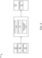
- FIG. 4 illustrates an example data flow 400 for generating a fused object bounding box based on uncertainty, in accordance with techniques of this disclosure.
- Input 402 includes two sensor-based bounding boxes, a radar bounding box 404 and a vision bounding box 406.
- the input 402 can alternatively or additionally include bounding boxes derived from any other sensor data (e.g., LiDAR data, ultrasonic data, infrared data) alone or in combination with the radar bounding box 404 and/or the vision bounding box 406.
- sensor data e.g., LiDAR data, ultrasonic data, infrared data
- the bounding box fusion module 408 receives the radar bounding box 404 and the vision bounding box 406 and performs a fusion type determination 410.
- the fusion type determination 410 determines how much uncertainty is inherent in the radar bounding box 404 and the vision bounding box 406 by calculating a discrepancy of certain parameters (e.g., center point, yaw angle, length, width) between the radar bounding box 404 and the vision bounding box 406.
- x and y are the coordinates of the center value
- v x and v y are the velocity of the bounding box for the x-axis and y-axis respectively
- ⁇ is the yaw angle
- / is the length
- h is the width of a bounding box.
- the uncertainty can include the accuracy of the underlying sensor, external conditions such as weather, or other factors.
- a refined fusion type or a consolidation fusion type is chosen based on whether the discrepancy is less than a threshold value or greater than (e.g., greater than or equal to) the threshold value.
- a smaller discrepancy that is less than the threshold value implies less uncertainty in the input 402.
- a larger discrepancy that is greater than or equal to the threshold value implies more uncertainty in the input 402.
- a fusion covariance determination 412 is performed.
- the mean value of the parameters or of the normal distributions of the parameters is used to determine an intersection of the radar bounding box 404 and the vision bounding box 406.
- the union of the parameters or of the normal distributions of the parameters is determined.
- an output 414 that includes a fused bounding box 416 is generated.
- the fused bounding box 416 may be a more conservative estimate of the location of the related object and, thus, a safer estimate that results in a more stable tracking performance than other bounding box fusion techniques.
- FIG. 5 illustrates the fusion types associated with generating a fused object bounding box based on uncertainty, in accordance with techniques of this disclosure.
- a fused bounding box 502 from sensor-based bounding boxes (e.g., a radar bounding box 504 and a vision bounding box 506)
- the uncertainty of each respective bounding box may be calculated.
- p r and p v are the coefficients for the radar bounding box 504 and the vision bounding box 506, respectively.
- the center point is distributed by a two-dimensional normal distribution.
- the fusion type depends on the discrepancy between the radar bounding box 504 and the vision bounding box 506.
- ⁇ , ⁇ , and y are tunable parameters that may be determined from different methods such as analysis of large test data sets.
- v x,r and v x,v are the x-axis velocity for the bounding box given by radar and vision, respectively.
- v y,r and v y,v are the y-axis velocity for the bounding box given by radar and vision, respectively.
- the length and width of the bounding box is denoted by l and h.
- the two fusion types, the refined fusion and the consolidation fusion, are chosen based on the value of the discrepancy, d . If the value of the discrepancy is greater than or equal to a threshold value, the consolidation fusion type is used to fuse the bounding boxes.
- the refined fusion type is performed.
- Var x P ⁇ 1 ⁇ P r ⁇ 1 x r + 1 ⁇ ⁇ P v ⁇ 1 x v where ⁇ is an assigned weight.
- FIG. 6 illustrates an example method 600 for generating a fused object bounding box based on uncertainty, in accordance with techniques of this disclosure.
- a first bounding box based on first sensor data from a first sensor
- a second bounding box based on second sensor data from a second sensor
- first sensor has been described as a radar sensor
- the second sensor has been described as a camera sensor.
- any sensor used for detecting and tracking objects may be used.
- an uncertainty associated with the first bounding box and the second bounding box is quantified.
- This uncertainty may be a discrepancy between corresponding parameters of the first bounding box and the second bounding box.
- the discrepancy may be the distance between the center points of the first bounding box and the second bounding box.
- a fused bounding box for the object is generated based on the uncertainty.
- the generation of the fused bounding box may be one of two types, a refined fusion or a consolidation fusion.
- the refined fusion type finds the intersection between the first bounding box and the second bounding box and is used when the discrepancy is small.
- the consolidation fusion type calculates the union between the normal distribution of the parameters of the first bounding box and the second bounding box.
- the consolidation fusion type is used when the discrepancy is larger. This larger discrepancy is considered, and a larger fused bounding box may be generated to compensate for the larger uncertainty.
- the fused bounding box is output to an object tracker for tracking an object.
- the fused bounding box generated using the methods described herein may reduce jitteriness or "jumping" by the fused bounding box around the object. By considering the uncertainty, the object tracker may perform better and lead to increased safety.
- Example 1 A method comprising: obtaining, based on first sensor data from a first sensor, a first bounding box for an object in a field of view of the first sensor; obtaining, based on second sensor data from a second sensor, a second bounding box for the object in a field of view of the second sensor; quantifying, based on at least one parameter of the first bounding box and at least one parameter of the second bounding box, an uncertainty associated with the first bounding box and the second bounding box; generating, based on the quantified uncertainty, a fused bounding box for the object; and outputting the fused bounding box to an object tracker for tracking the object.
- Example 2 The method of example 1, wherein the at least one parameter of the first bounding box and the at least one parameter of the second bounding box comprises at least one of: a center point of the respective bounding box; a yaw angle associated with the respective bounding box; a length of the bounding box; a width of the bounding box; an x-axis velocity of the bounding box; or a y-axis velocity of the bounding box.
- Example 3 The method of any one of the preceding claims, wherein quantifying the uncertainty comprises: determining a discrepancy between the at least one parameter of the first bounding box and the corresponding at least one parameter of the second bounding box.
- Example 4 The method of any one of the preceding claims, wherein determining the discrepancy comprises: determining a distance between a center point of the first bounding box and a center point of the second bounding box; determining a difference between a length of the first bounding box and a length of the second bounding box; determining a difference between a width of the first bounding box and a width of the second bounding box; determining a difference between an x-axis velocity of the first bounding box and an x-axis velocity of the second bounding box; and determining a difference between a y-axis velocity of the first bounding box and a y-axis velocity of the second bounding box
- Example 5 The method of any one of the preceding claims, wherein quantifying the uncertainty further comprises: determining a combined distribution associated with the at least one parameter of the first bounding box and the corresponding at least one parameter of the second bounding box.
- Example 6 The method of any one of the preceding claims, wherein generating the fused bounding box comprises: comparing the discrepancy to a threshold value; responsive to the discrepancy being below the threshold value, determining, based on the combined distribution, an intersection between the first bounding box and the second bounding box; and generating, based on the intersection, the fused bounding box.
- Example 7 The method of any one of the preceding claims, wherein determining the intersection comprises: determining, based on the combined distribution, a weight for each parameter of the at least one parameter of the first bounding box and the corresponding at least one parameter of the second bounding box.
- Example 8 The method of any one of the preceding claims, wherein the intersection is a covariance intersection.
- Example 9 The method of any one of the preceding claims, wherein generating the fused bounding box comprises: comparing the discrepancy to a threshold value; responsive to the discrepancy being above or equal to the threshold value, determining, based on the combined distribution, a union of the first bounding box and the second bounding box; and generating, based on the union, the fused bounding box.
- Example 10 The method of any one of the preceding claims, wherein determining the union comprises: calculating, based on a mean value of the at least one parameter of the first bounding box and the corresponding at least one parameter of the second bounding box, a covariance matrix representing an approximation of the union.
- Example 11 The method of any one of the preceding claims, wherein the approximation of the union is a Gaussian mixture.
- Example 12 A system comprising: at least one processor configured to: obtain, based on first sensor data from a first sensor, a first bounding box for an object in a field of view of the first sensor; obtain, based on second sensor data from a second sensor, a second bounding box for the object in a field of view of the second sensor; quantify, based on at least one parameter of the first bounding box and at least one parameter of the second bounding box, an uncertainty associated with the first bounding box and the second bounding box; generate, based on the quantified uncertainty, a fused bounding box for the object; and output the fused bounding box to an object tracker for tracking the object.
- Example 13 The system of any one of the preceding claims, wherein the at least one parameter of the first bounding box and the at least one parameter of the second bounding box comprises at least one of: a center point of the respective bounding box; a yaw angle associated with the respective bounding box; a length of the bounding box; a width of the bounding box; an x-axis velocity of the bounding box; or a y-axis velocity of the bounding box.
- Example 14 The system of any one of the preceding claims, wherein the at least one processor is configured to quantify the uncertainty by at least: determining a discrepancy between the at least one parameter of the first bounding box and the corresponding at least one parameter of the second bounding box.
- Example 15 The system of any one of the preceding claims, wherein the at least one processor is configured to determine the discrepancy by at least: determining a distance between a center point of the first bounding box and a center point of the second bounding box; determining a difference between a length of the first bounding box and a length of the second bounding box; and determining a difference between a width of the first bounding box and a width of the second bounding box.
- Example 16 The system of any one of the preceding claims, wherein the at least one processor is configured to generate the fused bounding box by at least: comparing the discrepancy to a threshold value; responsive to the discrepancy being below the threshold value, determining, based a combined distribution of the at least one parameter of the first bounding box and the corresponding at least one parameter of the second bounding box, an intersection between the first bounding box and the second bounding box; and generating, based on the intersection, the fused bounding box.
- Example 17 The system of any one of the preceding claims, wherein the at least one processor is configured to determine the intersection by at least: determining, based on the combined distribution, a weight for each parameter of the at least one parameter of the first bounding box and the corresponding at least one parameter of the second bounding box.
- Example 18 The system of any one of the preceding claims, wherein the at least one processor is configured to generate the fused bounding box by at least: comparing the discrepancy to a threshold value; responsive to the discrepancy being above or equal to the threshold value, determining, based a combined distribution of the at least one parameter of the first bounding box and the corresponding at least one parameter of the second bounding box, a union between the first bounding box and the second bounding box; and generating, based on the union, the fused bounding box.
- Example 19 The system of any one of the preceding claims, wherein the at least one processor is configured to determine the union by at least: calculating, based on a mean value of the at least one parameter of the first bounding box and the corresponding at least one parameter of the second bounding box, a covariance matrix representing an approximation of the union.
- Example 20 A computer-readable storage media comprising instructions that, when executed, configure a processor to: obtain, based on first sensor data from a first sensor, a first bounding box for an object in a field of view of the first sensor; obtain, based on second sensor data from a second sensor, a second bounding box for the object in a field of view of the second sensor; quantify, based on at least one parameter of the first bounding box and at least one parameter of the second bounding box, an uncertainty associated with the first bounding box and the second bounding box; generate, based on the quantified uncertainty, a fused bounding box for the object; and output the fused bounding box to an object tracker for tracking the object.
- "at least one of: a, b, or c” is intended to cover a, b, c, a-b, a-c, b-c, and a-b-c, as well as any combination with multiples of the same element (e.g., a-a, a-a-a, a-a-b, a-a-c, a-b-b, a-c-c, b-b, b-b-b, b-b-c, c-c, and c-c-c or any other ordering of a, b, and c).
Abstract
Description
- In some automobiles, a sensor fusion system (e.g., a fusion tracker) may combine information obtained from multiple sensors to support autonomous or semi-autonomous controls. The fused sensor data can be used to infer position, velocity, trajectory, size, class, and other parameters of objects within a field-of-view of the sensors. Sensor fusion is critical for environmental perception and trajectory; however, over-estimation or under-estimation of the uncertainty of the sensor data being fused may lead to poor fusion tracking performance.
- This document describes techniques and systems for generating a fused object bounding box based on uncertainty. At least two bounding boxes, each associated with a different sensor, is generated. A fused center point and yaw angle, as well as length, width, and velocity, can be found by mixing the distributions of the parameters from each bounding box. A discrepancy can be found between the center points of each bounding box and is used to determine whether to refine the fused bounding box (e.g., find an intersection between the at least two bounding boxes) or consolidate the fused bounding box (e.g., find a union between the at least two bounding boxes). This results in the fused bounding box having a confidence level of the uncertainty associated with the fused bounding box. In this manner, better estimations of the uncertainty of the fused bounding box may be achieved to improve tracking performance of a sensor fusion system.
- Aspects described below include generating a fused bounding box based on uncertainty. In one example, a method includes obtaining, based on first sensor data from a first sensor, a first bounding box for an object in a field of view of the first sensor. The method further includes obtaining, based on second sensor data from a second sensor, a second bounding box for the object in a field of view of the second sensor. The method further includes quantifying, based on at least one parameter of the first bounding box and at least one parameter of the second bounding box, an uncertainty associated with the first bounding box and the second bounding box. The method further includes generating, based on the quantified uncertainty, a fused bounding box for the object. The method further includes outputting the fused bounding box for tracking the object.
- These and other described techniques may be performed by hardware or a combination of hardware and software executing thereon. For example, a computer-readable storage media (CRM) may have instructions stored thereon and that when executed configure a processor to perform the described techniques. A system may include means for performing the described techniques. A processor or processor unit may be part of a system that is configured to execute the methods and techniques described herein.
- Through implementation of these and other examples contemplated by this disclosure, stability in an object tracker can be achieved by generating a fused object bounding box based on uncertainty. This Summary introduces simplified concepts related to generating a fused object bounding box based on uncertainty, further described in the Detailed Description and Drawings. This Summary is not intended to identify essential features of the claimed subject matter, nor is it intended for use in determining the scope of the claimed subject matter.
- The details of one or more aspects of generating a fused object bounding box based on uncertainty are described in this document with reference to the following figures that may use same numbers to reference like features and components, and hyphenated numbers to designate variations of these like features and components. The Drawings are organized as follows:
-
FIG. 1 illustrates an example operating environment of a vehicle that is configured for generating a fused object bounding box based on uncertainty, in accordance with techniques of this disclosure; -
Fig. 2 illustrates an example of an automotive system for generating a fused object bounding box based on uncertainty, in accordance with techniques of this disclosure; -
FIG. 3 illustrates a general example of generating a fused object bounding box based on uncertainty, in accordance with techniques of this disclosure; -
FIG. 4 illustrates an example data flow for generating a fused object bounding box based on uncertainty, in accordance with techniques of this disclosure; -
FIG. 5 illustrates the fusion types associated with generating a fused object bounding box based on uncertainty, in accordance with techniques of this disclosure; and -
FIG. 6 illustrates an example method for generating a fused object bounding box based on uncertainty, in accordance with techniques of this disclosure. - Automotive technology is successfully increasing autonomy and safety. One way to achieve this includes equipping vehicles with many different types of sensors, including optical cameras, radar systems, and light detection and ranging (LiDAR) systems. The sensors collect data that are processed by sensor fusion systems to generate tracks or bounding boxes, representing different objects in the environment surrounding the vehicle. These objects may be dynamic or stationary and may include pedestrians, animals, other vehicles, vegetation, buildings, street signs, and many other elements that may exist in the environment.
- Bounding boxes associated with different sensors can be fused to generate a fused bounding box. Fused bounding boxes can take advantage of the strengths of the different types of sensors and minimize the weaknesses. However, current methods for fusing bounding boxes have some drawbacks. The fusion process may not consider the uncertainty of the sensor data. That is, in any given data frame, data from one sensor may be more accurate than data from another sensor. This can lead to the fused bounding box to only partially encompass the object, or the fused bounding box can become unstable. This instability manifests as the fused bounding box being jittery, or "jumping" around the object.
- In contrast, the techniques disclosed below describe generating a fused bounding box based on uncertainty. Multiple sensor-based bounding boxes can serve as input. Parameters of these bounding boxes, including center point, yaw angle, length and width can be compared to one another. The comparison may also include tunable parameters for each bounding box being compared. These tunable parameters may be derived from expert opinion, analysis (e.g., statistical analysis, machine-learning-based analysis) of large test data sets, or by other methods. The comparison of the multiple bounding box results in calculating a discrepancy between the bounding boxes being compared. Based on the size of the discrepancy, either a refined fusion technique or a consolidation fusion technique can be used to fuse the sensor-based bounding boxes. The refined fusion technique fuses the sensor-based bounding boxes based on the intersection of the normal distributions and/or mean values of the parameters of the sensor-based bounding boxes. The consolidation fusion technique bases the fusion of the sensor-based bounding boxes on the union of the normal distributions of each respective sensor-based bounding box.
- The fused bounding box, being generated based on the statistical distributions including the mean values and covariance values of the sensor-based bounding boxes may reduce instability and increase accuracy. By fusing the bounding boxes in this manner, any uncertainty related to each bounding box can be considered to provide a conservative estimate of the location of the object that may result in a safe and reliable tracking system.
-
FIG. 1 illustrates anexample operating environment 100 of avehicle 102 that is configured for generating a fused object bounding box based on uncertainty, in accordance with techniques of this disclosure. In the depictedenvironment 100, a sensor-fusion system 104 is mounted to, or integrated within, thevehicle 102. Although illustrated as a car, thevehicle 102 can represent other types of vehicles and machinery (e.g., a motorcycle, a bus, a tractor, a semitrailer truck, watercraft, aircraft, or other heavy equipment) including manned and unmanned systems that may be used for a variety of purposes. - The sensor-fusion system 104 may include one or more sensor interfaces 106-1 through 106-n (collectively "
sensor interfaces 106"), abounding box generator 108, a bounding box fusion module 110, and anobject tracker module 112. In other examples, the operations associated with the radar system 204 can be performed using a different arrangement or quantity of components than that shown inFIG. 1 . - The sensor interfaces 106-1 through 106-n may include a camera interface 106-1, a radar interface 106-2, and one or more other sensor interfaces 106-n. Each of the
sensor interfaces 106 provides the sensor-fusion system 104 with sensor data of a particular type. For example, the camera interface 106-1 obtains vision data generated by one or more camera sensors, and the radar interface 106-2 obtains radar data from a set of radar sensors in communication with the radar interface 106-2. The vision data and the radar data correspond to objects (e.g., an object 114) within a respective field-of-view (FOV) 116 of the sensors equipped on thevehicle 102. - In general, manufacturers can mount the sensors and the sensor-fusion system 104 to any moving platform that can travel in the
environment 100. The sensors can project their respective FOVs from any exterior surface of thevehicle 102. For example, vehicle manufacturers can integrate at least a part of the sensor-fusion system 104 (e.g., the sensors) into a side mirror, bumper, roof, or any other interior or exterior location where theFOV 116 includes a portion of theenvironment 100 and objects moving or stationary that are in theenvironment 100. Manufacturers can design the location of the sensors to provide a particular FOV that sufficiently encompasses portions of theenvironment 100 in which thevehicle 102 may be traveling. In the depicted implementation, a portion of the sensor-fusion system 104 is mounted near the front bumper section of thevehicle 102. - The
bounding box generator 108 can receive the vision data and the radar data associated with theobject 114 and generate avision bounding box 118 and aradar bounding box 120. In other aspects, thevision bounding box 118 and theradar bounding box 120 can be generated prior to being received by the sensor fusion system 104 (e.g., each sensor system may include a respective bounding box generator). The bounding box fusion module 110 can receive thevision bounding box 118 and theradar bounding box 120 and fuse them to generate a fusedbounding box 122. The fusedbounding box 122 can be output to theobject tracker module 112 to track objects (e.g., the object 114) in theFOV 116. - The fused
bounding box 122 includes uncertainty associated with thevision bounding box 118 and theradar bounding box 120. Since the fusedbounding box 122 includes uncertainty inherent in the respective sensor data, the fusedbounding box 122 represents a more conservative estimate of the location of theobject 114 in any given data frame. By including a quantified uncertainty in the fusedbounding box 122, the fusedbounding box 122 can be more stable (e.g., less jumping of object positions) and may result in better tracking performance by theobject tracker module 112. -
Fig. 2 illustrates an example of anautomotive system 200 for generating a fused object bounding box based on uncertainty, in accordance with techniques of this disclosure. Theautomotive system 200 can be integrated within thevehicle 102. For example, theautomotive system 200 includes acontroller 202 and a sensor-fusion system 104-1. The sensor-fusion system 104-1 is an example of the sensor-fusion system 104 and can be integrated into an automotive or other vehicular environment. The sensor-fusion system 104-1 and thecontroller 202 communicate over a link 212. The link 212 may be a wired or wireless link and in some cases includes a communication bus. Thecontroller 202 performs operations based on information received over the link 212, such as data output from the sensor-fusion system 104 as objects in theFOV 116 are identified from processing and fusing sensor data associated with objects. - The
controller 202 includes a processor 204-1 and a computer-readable storage medium (CRM) 206-1 (e.g., a memory, long-term storage, short-term storage), which stores instructions for anautomotive module 208. The sensor-fusion system 104-1 includes a camera interface 106-1 and a radar interface 106-2. The sensor-fusion system 104-1 may also include other sensor interfaces. The sensor-fusion system 104-1 may include processing hardware that includes a processor 204-2 and a computer-readable storage medium (CRM) 206-2, which stores instructions associated with a bounding box generator 108-1, a bounding box fusion module 110-1, and an object tracker module 112-1. - The bounding box generator 108-1, which is an example of the
bounding box generator 108, includes a vision bounding box module 210-1 and a radar bounding box generator 210-2. The bounding box generator 108-1 receives camera data from the camera interface 106-1 related to an object in the FOV of a camera and generates a vision bounding box for the object. Likewise, the bounding box generator 108-1 receives radar data from the radar interface 106-2 related to the object and generates a radar bounding box for the object. In some cases, the vision bounding box and the radar bounding box have parameters (e.g., center point, yaw angle, length, width) with values that are similar. That is, the uncertainty associated with each respective bounding box is relatively small since the discrepancies between the respective parameter values of the bounding boxes are also small. In other cases, the respective parameter values can have a larger discrepancy (e.g., difference). This larger discrepancy leads to more uncertainty related to one or both bounding boxes. Further, the discrepancy can be relatively small in one data frame and relatively large in another data frame. These bounding boxes can be used separately to locate and track objects, or they can be output to the bounding box fusion module 110-1 for further processing. - The bounding box fusion module 110-1, which is an example of the bounding box fusion module 110, includes a fusion type submodule 214-1 and a fusion covariance submodule 214-2. The fusion type submodule 214-1 receives the vision bounding box and the radar bounding box and determines the discrepancy between the parameters of the two bounding boxes. The amount of discrepancy determines whether the fusion type is an intersection fusion (e.g., low uncertainty cases) or a union fusion (e.g., high uncertainty cases). For example, if the discrepancy is below a threshold value, the fusion type is an intersection fusion. Otherwise, the fusion type is a union fusion. Once the fusion type is determined, the fusion covariance submodule determines the covariance of the fused bounding box and generates the fused bounding box. These procedures may be performed on any quantity of bounding boxes derived from multiple different sensor data. The object tracker module 112-1 can use the fused bounding box to track the object in an environment. By basing the fused bounding box on the uncertainty of the separate bounding boxes, the fused bounding may be more stable and robust to noise, and the tracking performance may be improved.
-
FIG. 3 illustrates a general example 300 of generating a fused object bounding box based on uncertainty, in accordance with techniques of this disclosure. A sensor fusion system (not shown) may receive sensor data from two or more sensors related to anobject 302 and generate bounding boxes 304 based on the sensor data. In this example, a radar bounding box 304-1 and a vision bounding box 304-2 are generated for theobject 302. The radar bounding box 304-1 and the sensor bounding box 304-2 include a center point 306-1 and a center point 306-2, respectively. - Based on the center points 306 of the radar bounding box 304-1 and the sensor bounding box 304-2 and other parameters such as the yaw angle, length, and/or width of the bounding boxes 304, the sensor fusion system can generate a fused
bounding box 308 with acenter point 310 for theobject 302. The fusedbounding box 308 may be a close approximation of the location, direction, and boundaries of theobject 302. Because the fusedbounding box 308 is generated from two or more separate bounding boxes that have a certain amount of uncertainty each, in many current fusion systems the fusedbounding box 308 could become unstable and jitter around theobject 302 from frame to frame. However, generating the fusedbounding box 308 based on uncertainty as described herein accounts for the uncertainty including noise in the sensor data and may result in a more robust tracking system and better tracking performance. -
FIG. 4 illustrates anexample data flow 400 for generating a fused object bounding box based on uncertainty, in accordance with techniques of this disclosure.Input 402 includes two sensor-based bounding boxes, aradar bounding box 404 and avision bounding box 406. In some aspects, theinput 402 can alternatively or additionally include bounding boxes derived from any other sensor data (e.g., LiDAR data, ultrasonic data, infrared data) alone or in combination with theradar bounding box 404 and/or thevision bounding box 406. - The bounding
box fusion module 408 receives theradar bounding box 404 and thevision bounding box 406 and performs a fusion type determination 410. The fusion type determination 410 determines how much uncertainty is inherent in theradar bounding box 404 and thevision bounding box 406 by calculating a discrepancy of certain parameters (e.g., center point, yaw angle, length, width) between theradar bounding box 404 and thevision bounding box 406. For example, the uncertainty can be expressed as a normal distribution
input 402. A larger discrepancy that is greater than or equal to the threshold value implies more uncertainty in theinput 402. - Once the fusion type is determined, a fusion covariance determination 412 is performed. For a refined fusion type, the mean value of the parameters or of the normal distributions of the parameters is used to determine an intersection of the
radar bounding box 404 and thevision bounding box 406. For a consolidation fusion type, the union of the parameters or of the normal distributions of the parameters is determined. - Based on the fusion covariance determination 412, an output 414 that includes a fused
bounding box 416 is generated. The fusedbounding box 416 may be a more conservative estimate of the location of the related object and, thus, a safer estimate that results in a more stable tracking performance than other bounding box fusion techniques. -
FIG. 5 illustrates the fusion types associated with generating a fused object bounding box based on uncertainty, in accordance with techniques of this disclosure. To generate a fusedbounding box 502 from sensor-based bounding boxes (e.g., a radar bounding box 504 and a vision bounding box 506), the uncertainty of each respective bounding box may be calculated. In general, a simplified bounding box uncertainty may be represented by a normal distribution
FIG. 5 represent the radar bounding boxnormal distribution 508 and the vision bounding boxnormal distribution 510. Other parameters such as the length, width, and velocity of the bounding box may also be evaluated. The fused yaw angle can be described by combining the distributions of the radar bounding box 504 and the vision bounding box 506

- The fusion type depends on the discrepancy between the radar bounding box 504 and the vision bounding box 506. The discrepancy metric can be described as the distance between the center point (and/or other parameters) of the radar bounding box 504 and the vision bounding box 506

- The two fusion types, the refined fusion and the consolidation fusion, are chosen based on the value of the discrepancy, d. If the value of the discrepancy is greater than or equal to a threshold value, the consolidation fusion type is used to fuse the bounding boxes. The consolidation fusion type uses the normal distribution of the parameters, which can be described in general as


Gaussian mixture 512 or covariance union of the radar bounding box 504-1 and the vision bounding box 506-1. - If the discrepancy is less than the threshold value, the refined fusion type is performed. To refine the uncertainty, the
covariance intersection 514 between the radar bounding box 504-2 and the vision bounding box 506-2 is calculated as


- In this manner, the uncertainty of the bounding boxes can be considered resulting in a safer and more accurate tracker.
-
FIG. 6 illustrates anexample method 600 for generating a fused object bounding box based on uncertainty, in accordance with techniques of this disclosure. Atstep 602, a first bounding box, based on first sensor data from a first sensor, is obtained, and atstep 604, a second bounding box, based on second sensor data from a second sensor, is obtained. Throughout this document the first sensor has been described as a radar sensor, and the second sensor has been described as a camera sensor. However, any sensor used for detecting and tracking objects may be used. - At
step 606, an uncertainty associated with the first bounding box and the second bounding box is quantified. This uncertainty may be a discrepancy between corresponding parameters of the first bounding box and the second bounding box. For example, the discrepancy may be the distance between the center points of the first bounding box and the second bounding box. - At
step 608, a fused bounding box for the object is generated based on the uncertainty. The generation of the fused bounding box may be one of two types, a refined fusion or a consolidation fusion. The refined fusion type finds the intersection between the first bounding box and the second bounding box and is used when the discrepancy is small. The consolidation fusion type calculates the union between the normal distribution of the parameters of the first bounding box and the second bounding box. The consolidation fusion type is used when the discrepancy is larger. This larger discrepancy is considered, and a larger fused bounding box may be generated to compensate for the larger uncertainty. - At
step 610, the fused bounding box is output to an object tracker for tracking an object. The fused bounding box generated using the methods described herein may reduce jitteriness or "jumping" by the fused bounding box around the object. By considering the uncertainty, the object tracker may perform better and lead to increased safety. - Example 1: A method comprising: obtaining, based on first sensor data from a first sensor, a first bounding box for an object in a field of view of the first sensor; obtaining, based on second sensor data from a second sensor, a second bounding box for the object in a field of view of the second sensor; quantifying, based on at least one parameter of the first bounding box and at least one parameter of the second bounding box, an uncertainty associated with the first bounding box and the second bounding box; generating, based on the quantified uncertainty, a fused bounding box for the object; and outputting the fused bounding box to an object tracker for tracking the object.
- Example 2: The method of example 1, wherein the at least one parameter of the first bounding box and the at least one parameter of the second bounding box comprises at least one of: a center point of the respective bounding box; a yaw angle associated with the respective bounding box; a length of the bounding box; a width of the bounding box; an x-axis velocity of the bounding box; or a y-axis velocity of the bounding box.
- Example 3: The method of any one of the preceding claims, wherein quantifying the uncertainty comprises: determining a discrepancy between the at least one parameter of the first bounding box and the corresponding at least one parameter of the second bounding box.
- Example 4: The method of any one of the preceding claims, wherein determining the discrepancy comprises: determining a distance between a center point of the first bounding box and a center point of the second bounding box; determining a difference between a length of the first bounding box and a length of the second bounding box; determining a difference between a width of the first bounding box and a width of the second bounding box; determining a difference between an x-axis velocity of the first bounding box and an x-axis velocity of the second bounding box; and determining a difference between a y-axis velocity of the first bounding box and a y-axis velocity of the second bounding box
- Example 5: The method of any one of the preceding claims, wherein quantifying the uncertainty further comprises: determining a combined distribution associated with the at least one parameter of the first bounding box and the corresponding at least one parameter of the second bounding box.
- Example 6: The method of any one of the preceding claims, wherein generating the fused bounding box comprises: comparing the discrepancy to a threshold value; responsive to the discrepancy being below the threshold value, determining, based on the combined distribution, an intersection between the first bounding box and the second bounding box; and generating, based on the intersection, the fused bounding box.
- Example 7: The method of any one of the preceding claims, wherein determining the intersection comprises: determining, based on the combined distribution, a weight for each parameter of the at least one parameter of the first bounding box and the corresponding at least one parameter of the second bounding box.
- Example 8: The method of any one of the preceding claims, wherein the intersection is a covariance intersection.
- Example 9: The method of any one of the preceding claims, wherein generating the fused bounding box comprises: comparing the discrepancy to a threshold value; responsive to the discrepancy being above or equal to the threshold value, determining, based on the combined distribution, a union of the first bounding box and the second bounding box; and generating, based on the union, the fused bounding box.
- Example 10: The method of any one of the preceding claims, wherein determining the union comprises: calculating, based on a mean value of the at least one parameter of the first bounding box and the corresponding at least one parameter of the second bounding box, a covariance matrix representing an approximation of the union.
- Example 11: The method of any one of the preceding claims, wherein the approximation of the union is a Gaussian mixture.
- Example 12: A system comprising: at least one processor configured to: obtain, based on first sensor data from a first sensor, a first bounding box for an object in a field of view of the first sensor; obtain, based on second sensor data from a second sensor, a second bounding box for the object in a field of view of the second sensor; quantify, based on at least one parameter of the first bounding box and at least one parameter of the second bounding box, an uncertainty associated with the first bounding box and the second bounding box; generate, based on the quantified uncertainty, a fused bounding box for the object; and output the fused bounding box to an object tracker for tracking the object.
- Example 13: The system of any one of the preceding claims, wherein the at least one parameter of the first bounding box and the at least one parameter of the second bounding box comprises at least one of: a center point of the respective bounding box; a yaw angle associated with the respective bounding box; a length of the bounding box; a width of the bounding box; an x-axis velocity of the bounding box; or a y-axis velocity of the bounding box.
- Example 14: The system of any one of the preceding claims, wherein the at least one processor is configured to quantify the uncertainty by at least: determining a discrepancy between the at least one parameter of the first bounding box and the corresponding at least one parameter of the second bounding box.
- Example 15: The system of any one of the preceding claims, wherein the at least one processor is configured to determine the discrepancy by at least: determining a distance between a center point of the first bounding box and a center point of the second bounding box; determining a difference between a length of the first bounding box and a length of the second bounding box; and determining a difference between a width of the first bounding box and a width of the second bounding box.
- Example 16: The system of any one of the preceding claims, wherein the at least one processor is configured to generate the fused bounding box by at least: comparing the discrepancy to a threshold value; responsive to the discrepancy being below the threshold value, determining, based a combined distribution of the at least one parameter of the first bounding box and the corresponding at least one parameter of the second bounding box, an intersection between the first bounding box and the second bounding box; and generating, based on the intersection, the fused bounding box.
- Example 17: The system of any one of the preceding claims, wherein the at least one processor is configured to determine the intersection by at least: determining, based on the combined distribution, a weight for each parameter of the at least one parameter of the first bounding box and the corresponding at least one parameter of the second bounding box.
- Example 18: The system of any one of the preceding claims, wherein the at least one processor is configured to generate the fused bounding box by at least: comparing the discrepancy to a threshold value; responsive to the discrepancy being above or equal to the threshold value, determining, based a combined distribution of the at least one parameter of the first bounding box and the corresponding at least one parameter of the second bounding box, a union between the first bounding box and the second bounding box; and generating, based on the union, the fused bounding box.
- Example 19: The system of any one of the preceding claims, wherein the at least one processor is configured to determine the union by at least: calculating, based on a mean value of the at least one parameter of the first bounding box and the corresponding at least one parameter of the second bounding box, a covariance matrix representing an approximation of the union.
- Example 20: A computer-readable storage media comprising instructions that, when executed, configure a processor to: obtain, based on first sensor data from a first sensor, a first bounding box for an object in a field of view of the first sensor; obtain, based on second sensor data from a second sensor, a second bounding box for the object in a field of view of the second sensor; quantify, based on at least one parameter of the first bounding box and at least one parameter of the second bounding box, an uncertainty associated with the first bounding box and the second bounding box; generate, based on the quantified uncertainty, a fused bounding box for the object; and output the fused bounding box to an object tracker for tracking the object.
- While various embodiments of the disclosure are described in the foregoing description and shown in the drawings, it is to be understood that this disclosure is not limited thereto but may be variously embodied to practice within the scope of the following claims. From the foregoing description, it will be apparent that various changes may be made without departing from the spirit and scope of the disclosure as defined by the following claims. Problems associated with tracking performance can occur in other systems. Therefore, although described as a way to improve tracking performance of autonomous or semi-autonomous vehicles, the techniques of the foregoing description can be applied to other systems that would benefit from improved tracking performance of objects. Further, these techniques may also be applied to other systems that use various sensors to detect and track objects.
- The use of "or" and grammatically related terms indicates non-exclusive alternatives without limitation unless the context clearly dictates otherwise. As used herein, a phrase referring to "at least one of' a list of items refers to any combination of those items, including single members. As an example, "at least one of: a, b, or c" is intended to cover a, b, c, a-b, a-c, b-c, and a-b-c, as well as any combination with multiples of the same element (e.g., a-a, a-a-a, a-a-b, a-a-c, a-b-b, a-c-c, b-b, b-b-b, b-b-c, c-c, and c-c-c or any other ordering of a, b, and c).
Claims (15)
- A method comprising:obtaining, based on first sensor data from a first sensor, a first bounding box for an object in a field of view of the first sensor;obtaining, based on second sensor data from a second sensor, a second bounding box for the object in a field of view of the second sensor;quantifying, based on at least one parameter of the first bounding box and at least one parameter of the second bounding box, an uncertainty associated with the first bounding box and the second bounding box;generating, based on the quantified uncertainty, a fused bounding box for the object; andoutputting the fused bounding box to an object tracker for tracking the object.
- The method of claim 1, wherein the at least one parameter of the first bounding box and the at least one parameter of the second bounding box comprises at least one of:a center point of the respective bounding box;a yaw angle associated with the respective bounding box;a length of the bounding box;a width of the bounding box;an x-axis velocity of the bounding box; ora y-axis velocity of the bounding box.
- The method of any one of the preceding claims, wherein quantifying the uncertainty comprises:
determining a discrepancy between the at least one parameter of the first bounding box and the corresponding at least one parameter of the second bounding box. - The method of claim 3, wherein determining the discrepancy comprises:determining a distance between a center point of the first bounding box and a center point of the second bounding box;determining a difference between a length of the first bounding box and a length of the second bounding box;determining a difference between a width of the first bounding box and a width of the second bounding box;determining a difference between an x-axis velocity of the first bounding box and an x-axis velocity of the second bounding box; anddetermining a difference between a y-axis velocity of the first bounding box and a y-axis velocity of the second bounding box.
- The method of claims 3 or 4, wherein quantifying the uncertainty further comprises:
determining a combined distribution associated with the at least one parameter of the first bounding box and the corresponding at least one parameter of the second bounding box. - The method of claim 5, wherein generating the fused bounding box comprises:comparing the discrepancy to a threshold value;responsive to the discrepancy being below the threshold value, determining, based on the combined distribution, an intersection between the first bounding box and the second bounding box; andgenerating, based on the intersection, the fused bounding box.
- The method of claim 6, wherein determining the intersection comprises:
determining, based on the combined distribution, a weight for each parameter of the at least one parameter of the first bounding box and the corresponding at least one parameter of the second bounding box. - The method of claim 6, wherein the intersection is a covariance intersection.
- The method of any one of claims 5 through 8, wherein generating the fused bounding box comprises:comparing the discrepancy to a threshold value;responsive to the discrepancy being above or equal to the threshold value, determining, based on the combined distribution, a union of the first bounding box and the second bounding box; andgenerating, based on the union, the fused bounding box.
- The method of claim 9, wherein determining the union comprises:
calculating, based on a mean value of the at least one parameter of the first bounding box and the corresponding at least one parameter of the second bounding box, a covariance matrix or variance representing an approximation of the union. - The method of claim 10, wherein the approximation of the union is a Gaussian mixture.
- The method of any one of the preceding claims, wherein the first sensor and the second sensor are included in an automotive system comprising the object tracker.
- The method of any one of the preceding claims, wherein the method is executed by at least one processor of a vehicle.
- A system comprising at least one processor configured to perform the method of any one of the preceding claims 1-13.
- A computer-readable storage media comprising instructions that, when executed, configure a processor to perform the method of any one of the preceding claims 1-13.
Applications Claiming Priority (2)
| Application Number | Priority Date | Filing Date | Title |
|---|---|---|---|
| US202263266976P | 2022-01-20 | 2022-01-20 | |
| US17/804,074 US20230230255A1 (en) | 2022-01-20 | 2022-05-25 | Generating a Fused Object Bounding Box Based on Uncertainty |
Publications (1)
| Publication Number | Publication Date |
|---|---|
| EP4215933A1 true EP4215933A1 (en) | 2023-07-26 |
Family
ID=83692913
Family Applications (1)
| Application Number | Title | Priority Date | Filing Date |
|---|---|---|---|
| EP22197732.5A Pending EP4215933A1 (en) | 2022-01-20 | 2022-09-26 | Generating a fused object bounding box based on uncertainty |
Country Status (2)
| Country | Link |
|---|---|
| US (1) | US20230230255A1 (en) |
| EP (1) | EP4215933A1 (en) |
Citations (4)
| Publication number | Priority date | Publication date | Assignee | Title |
|---|---|---|---|---|
| US20130236047A1 (en) * | 2012-03-07 | 2013-09-12 | GM Global Technology Operations LLC | Enhanced data association of fusion using weighted bayesian filtering |
| WO2018020045A1 (en) * | 2016-07-29 | 2018-02-01 | Valeo Schalter Und Sensoren Gmbh | Merging of data for detecting and monitoring objects for a motor vehicle |
| WO2018148195A1 (en) * | 2017-02-08 | 2018-08-16 | Marquette University | Robotic tracking navigation with data fusion |
| US10936902B1 (en) * | 2018-11-27 | 2021-03-02 | Zoox, Inc. | Training bounding box selection |
-
2022
- 2022-05-25 US US17/804,074 patent/US20230230255A1/en active Pending
- 2022-09-26 EP EP22197732.5A patent/EP4215933A1/en active Pending
Patent Citations (4)
| Publication number | Priority date | Publication date | Assignee | Title |
|---|---|---|---|---|
| US20130236047A1 (en) * | 2012-03-07 | 2013-09-12 | GM Global Technology Operations LLC | Enhanced data association of fusion using weighted bayesian filtering |
| WO2018020045A1 (en) * | 2016-07-29 | 2018-02-01 | Valeo Schalter Und Sensoren Gmbh | Merging of data for detecting and monitoring objects for a motor vehicle |
| WO2018148195A1 (en) * | 2017-02-08 | 2018-08-16 | Marquette University | Robotic tracking navigation with data fusion |
| US10936902B1 (en) * | 2018-11-27 | 2021-03-02 | Zoox, Inc. | Training bounding box selection |
Non-Patent Citations (2)
| Title |
|---|
| GU CHUNZHI ET AL: "Merging Scored Bounding Boxes with Gaussian Mixture Model for Object Detection", PROCEEDINGS OF THE 6TH IIAE INTERNATIONAL CONFERENCE ON INTELLIGENT SYSTEMS AND IMAGE PROCESSING 2018, 1 January 2018 (2018-01-01), pages 249 - 255, XP093024648, ISBN: 978-4-907220-16-7, DOI: 10.12792/icisip2018.048 * |
| MATHWORKS: "Track-Level Fusion of Radar and Lidar Data - MATLAB & Simulink - MathWorks Benelux", 19 March 2020 (2020-03-19), pages 1 - 16, XP055849990, Retrieved from the Internet <URL:https://nl.mathworks.com/help/releases/R2020a/fusion/examples/track-level-fusion-of-radar-and-lidar-data.html> [retrieved on 20211011] * |
Also Published As
| Publication number | Publication date |
|---|---|
| US20230230255A1 (en) | 2023-07-20 |
Similar Documents
| Publication | Publication Date | Title |
|---|---|---|
| US10065654B2 (en) | Online learning and vehicle control method based on reinforcement learning without active exploration | |
| US11235757B2 (en) | Collision avoidance apparatus | |
| US20200238980A1 (en) | Vehicle control device | |
| US20160318513A1 (en) | Real-time anticipatory speed control | |
| US20170039865A1 (en) | Route prediction device | |
| US11708069B2 (en) | Obstacle avoidance apparatus and obstacle avoidance route generating apparatus | |
| CN106476728A (en) | Motion compensation for vehicle-mounted vehicle sensors | |
| US20200353918A1 (en) | Vehicle control device | |
| US10733233B2 (en) | Method and apparatus for generating situation awareness graphs using cameras from different vehicles | |
| CN111458700A (en) | Method and system for vehicle mapping and positioning | |
| JPWO2018212346A1 (en) | Control device, scanning system, control method, and program | |
| JP2019211830A (en) | Lane change estimation device and lane change estimation method, and vehicle control device and vehicle control method | |
| CN108974002B (en) | Vehicle control device, vehicle control method, and storage medium | |
| WO2021011185A1 (en) | Robust localization | |
| US20220105929A1 (en) | Method and Apparatus for Predicting Specification Motion of Other Vehicle | |
| US20190102633A1 (en) | Target object estimating apparatus | |
| US11780429B2 (en) | Target curvature estimation considering vehicle dynamics | |
| US20200369296A1 (en) | Autonomous driving apparatus and method | |
| EP4215933A1 (en) | Generating a fused object bounding box based on uncertainty | |
| CN116660871A (en) | Sensor offset correction | |
| CN116777984A (en) | System for calibrating external parameters of cameras in autonomous transportation vehicles | |
| CN116118770A (en) | Self-adaptive rationalizer of vehicle sensing system for robust automatic driving control | |
| CN116465415A (en) | Generating a fused object bounding box based on uncertainty | |
| KR20230117936A (en) | Autonomous driving apparatus and method of collision avoidance controlling the same | |
| US11279350B2 (en) | Method of adaptive trajectory generation for a vehicle |
Legal Events
| Date | Code | Title | Description |
|---|---|---|---|
| PUAI | Public reference made under article 153(3) epc to a published international application that has entered the european phase |
Free format text: ORIGINAL CODE: 0009012 |
|
| STAA | Information on the status of an ep patent application or granted ep patent |
Free format text: STATUS: THE APPLICATION HAS BEEN PUBLISHED |
|
| AK | Designated contracting states |
Kind code of ref document: A1 Designated state(s): AL AT BE BG CH CY CZ DE DK EE ES FI FR GB GR HR HU IE IS IT LI LT LU LV MC MK MT NL NO PL PT RO RS SE SI SK SM TR |
|
| STAA | Information on the status of an ep patent application or granted ep patent |
Free format text: STATUS: REQUEST FOR EXAMINATION WAS MADE |
|
| 17P | Request for examination filed |
Effective date: 20240123 |
|
| RBV | Designated contracting states (corrected) |
Designated state(s): AL AT BE BG CH CY CZ DE DK EE ES FI FR GB GR HR HU IE IS IT LI LT LU LV MC MK MT NL NO PL PT RO RS SE SI SK SM TR |