EP3951242A1 - Hydrogen gas supply device and hydrogen gas supply method - Google Patents
Hydrogen gas supply device and hydrogen gas supply method Download PDFInfo
- Publication number
- EP3951242A1 EP3951242A1 EP20779592.3A EP20779592A EP3951242A1 EP 3951242 A1 EP3951242 A1 EP 3951242A1 EP 20779592 A EP20779592 A EP 20779592A EP 3951242 A1 EP3951242 A1 EP 3951242A1
- Authority
- EP
- European Patent Office
- Prior art keywords
- compressor
- hydrogen gas
- adsorption column
- valve
- pressure
- Prior art date
- Legal status (The legal status is an assumption and is not a legal conclusion. Google has not performed a legal analysis and makes no representation as to the accuracy of the status listed.)
- Pending
Links
Images






Classifications
-
- F—MECHANICAL ENGINEERING; LIGHTING; HEATING; WEAPONS; BLASTING
- F17—STORING OR DISTRIBUTING GASES OR LIQUIDS
- F17C—VESSELS FOR CONTAINING OR STORING COMPRESSED, LIQUEFIED OR SOLIDIFIED GASES; FIXED-CAPACITY GAS-HOLDERS; FILLING VESSELS WITH, OR DISCHARGING FROM VESSELS, COMPRESSED, LIQUEFIED, OR SOLIDIFIED GASES
- F17C5/00—Methods or apparatus for filling containers with liquefied, solidified, or compressed gases under pressures
- F17C5/002—Automated filling apparatus
- F17C5/007—Automated filling apparatus for individual gas tanks or containers, e.g. in vehicles
-
- B—PERFORMING OPERATIONS; TRANSPORTING
- B01—PHYSICAL OR CHEMICAL PROCESSES OR APPARATUS IN GENERAL
- B01D—SEPARATION
- B01D53/00—Separation of gases or vapours; Recovering vapours of volatile solvents from gases; Chemical or biological purification of waste gases, e.g. engine exhaust gases, smoke, fumes, flue gases, aerosols
- B01D53/02—Separation of gases or vapours; Recovering vapours of volatile solvents from gases; Chemical or biological purification of waste gases, e.g. engine exhaust gases, smoke, fumes, flue gases, aerosols by adsorption, e.g. preparative gas chromatography
- B01D53/04—Separation of gases or vapours; Recovering vapours of volatile solvents from gases; Chemical or biological purification of waste gases, e.g. engine exhaust gases, smoke, fumes, flue gases, aerosols by adsorption, e.g. preparative gas chromatography with stationary adsorbents
- B01D53/047—Pressure swing adsorption
- B01D53/053—Pressure swing adsorption with storage or buffer vessel
-
- B—PERFORMING OPERATIONS; TRANSPORTING
- B01—PHYSICAL OR CHEMICAL PROCESSES OR APPARATUS IN GENERAL
- B01D—SEPARATION
- B01D53/00—Separation of gases or vapours; Recovering vapours of volatile solvents from gases; Chemical or biological purification of waste gases, e.g. engine exhaust gases, smoke, fumes, flue gases, aerosols
- B01D53/02—Separation of gases or vapours; Recovering vapours of volatile solvents from gases; Chemical or biological purification of waste gases, e.g. engine exhaust gases, smoke, fumes, flue gases, aerosols by adsorption, e.g. preparative gas chromatography
- B01D53/04—Separation of gases or vapours; Recovering vapours of volatile solvents from gases; Chemical or biological purification of waste gases, e.g. engine exhaust gases, smoke, fumes, flue gases, aerosols by adsorption, e.g. preparative gas chromatography with stationary adsorbents
- B01D53/0407—Constructional details of adsorbing systems
-
- B—PERFORMING OPERATIONS; TRANSPORTING
- B01—PHYSICAL OR CHEMICAL PROCESSES OR APPARATUS IN GENERAL
- B01D—SEPARATION
- B01D53/00—Separation of gases or vapours; Recovering vapours of volatile solvents from gases; Chemical or biological purification of waste gases, e.g. engine exhaust gases, smoke, fumes, flue gases, aerosols
- B01D53/02—Separation of gases or vapours; Recovering vapours of volatile solvents from gases; Chemical or biological purification of waste gases, e.g. engine exhaust gases, smoke, fumes, flue gases, aerosols by adsorption, e.g. preparative gas chromatography
- B01D53/04—Separation of gases or vapours; Recovering vapours of volatile solvents from gases; Chemical or biological purification of waste gases, e.g. engine exhaust gases, smoke, fumes, flue gases, aerosols by adsorption, e.g. preparative gas chromatography with stationary adsorbents
- B01D53/0407—Constructional details of adsorbing systems
- B01D53/0446—Means for feeding or distributing gases
-
- C—CHEMISTRY; METALLURGY
- C01—INORGANIC CHEMISTRY
- C01B—NON-METALLIC ELEMENTS; COMPOUNDS THEREOF; METALLOIDS OR COMPOUNDS THEREOF NOT COVERED BY SUBCLASS C01C
- C01B3/00—Hydrogen; Gaseous mixtures containing hydrogen; Separation of hydrogen from mixtures containing it; Purification of hydrogen; Reversible storage of hydrogen
- C01B3/50—Separation of hydrogen or hydrogen-containing gases from gaseous mixtures, e.g. purification
- C01B3/56—Separation of hydrogen or hydrogen-containing gases from gaseous mixtures, e.g. purification by contacting with solids; Regeneration of used solids
-
- F—MECHANICAL ENGINEERING; LIGHTING; HEATING; WEAPONS; BLASTING
- F17—STORING OR DISTRIBUTING GASES OR LIQUIDS
- F17C—VESSELS FOR CONTAINING OR STORING COMPRESSED, LIQUEFIED OR SOLIDIFIED GASES; FIXED-CAPACITY GAS-HOLDERS; FILLING VESSELS WITH, OR DISCHARGING FROM VESSELS, COMPRESSED, LIQUEFIED, OR SOLIDIFIED GASES
- F17C13/00—Details of vessels or of the filling or discharging of vessels
- F17C13/04—Arrangement or mounting of valves
-
- F—MECHANICAL ENGINEERING; LIGHTING; HEATING; WEAPONS; BLASTING
- F17—STORING OR DISTRIBUTING GASES OR LIQUIDS
- F17C—VESSELS FOR CONTAINING OR STORING COMPRESSED, LIQUEFIED OR SOLIDIFIED GASES; FIXED-CAPACITY GAS-HOLDERS; FILLING VESSELS WITH, OR DISCHARGING FROM VESSELS, COMPRESSED, LIQUEFIED, OR SOLIDIFIED GASES
- F17C5/00—Methods or apparatus for filling containers with liquefied, solidified, or compressed gases under pressures
- F17C5/06—Methods or apparatus for filling containers with liquefied, solidified, or compressed gases under pressures for filling with compressed gases
-
- F—MECHANICAL ENGINEERING; LIGHTING; HEATING; WEAPONS; BLASTING
- F17—STORING OR DISTRIBUTING GASES OR LIQUIDS
- F17C—VESSELS FOR CONTAINING OR STORING COMPRESSED, LIQUEFIED OR SOLIDIFIED GASES; FIXED-CAPACITY GAS-HOLDERS; FILLING VESSELS WITH, OR DISCHARGING FROM VESSELS, COMPRESSED, LIQUEFIED, OR SOLIDIFIED GASES
- F17C7/00—Methods or apparatus for discharging liquefied, solidified, or compressed gases from pressure vessels, not covered by another subclass
-
- B—PERFORMING OPERATIONS; TRANSPORTING
- B01—PHYSICAL OR CHEMICAL PROCESSES OR APPARATUS IN GENERAL
- B01D—SEPARATION
- B01D2253/00—Adsorbents used in seperation treatment of gases and vapours
- B01D2253/10—Inorganic adsorbents
- B01D2253/102—Carbon
-
- B—PERFORMING OPERATIONS; TRANSPORTING
- B01—PHYSICAL OR CHEMICAL PROCESSES OR APPARATUS IN GENERAL
- B01D—SEPARATION
- B01D2256/00—Main component in the product gas stream after treatment
- B01D2256/16—Hydrogen
-
- B—PERFORMING OPERATIONS; TRANSPORTING
- B01—PHYSICAL OR CHEMICAL PROCESSES OR APPARATUS IN GENERAL
- B01D—SEPARATION
- B01D2257/00—Components to be removed
- B01D2257/20—Halogens or halogen compounds
-
- B—PERFORMING OPERATIONS; TRANSPORTING
- B01—PHYSICAL OR CHEMICAL PROCESSES OR APPARATUS IN GENERAL
- B01D—SEPARATION
- B01D2257/00—Components to be removed
- B01D2257/30—Sulfur compounds
-
- B—PERFORMING OPERATIONS; TRANSPORTING
- B01—PHYSICAL OR CHEMICAL PROCESSES OR APPARATUS IN GENERAL
- B01D—SEPARATION
- B01D2259/00—Type of treatment
- B01D2259/40—Further details for adsorption processes and devices
- B01D2259/40007—Controlling pressure or temperature swing adsorption
-
- B—PERFORMING OPERATIONS; TRANSPORTING
- B01—PHYSICAL OR CHEMICAL PROCESSES OR APPARATUS IN GENERAL
- B01D—SEPARATION
- B01D2259/00—Type of treatment
- B01D2259/45—Gas separation or purification devices adapted for specific applications
- B01D2259/4525—Gas separation or purification devices adapted for specific applications for storage and dispensing systems
-
- C—CHEMISTRY; METALLURGY
- C01—INORGANIC CHEMISTRY
- C01B—NON-METALLIC ELEMENTS; COMPOUNDS THEREOF; METALLOIDS OR COMPOUNDS THEREOF NOT COVERED BY SUBCLASS C01C
- C01B2203/00—Integrated processes for the production of hydrogen or synthesis gas
- C01B2203/04—Integrated processes for the production of hydrogen or synthesis gas containing a purification step for the hydrogen or the synthesis gas
- C01B2203/042—Purification by adsorption on solids
-
- C—CHEMISTRY; METALLURGY
- C01—INORGANIC CHEMISTRY
- C01B—NON-METALLIC ELEMENTS; COMPOUNDS THEREOF; METALLOIDS OR COMPOUNDS THEREOF NOT COVERED BY SUBCLASS C01C
- C01B2203/00—Integrated processes for the production of hydrogen or synthesis gas
- C01B2203/04—Integrated processes for the production of hydrogen or synthesis gas containing a purification step for the hydrogen or the synthesis gas
- C01B2203/042—Purification by adsorption on solids
- C01B2203/043—Regenerative adsorption process in two or more beds, one for adsorption, the other for regeneration
-
- C—CHEMISTRY; METALLURGY
- C01—INORGANIC CHEMISTRY
- C01B—NON-METALLIC ELEMENTS; COMPOUNDS THEREOF; METALLOIDS OR COMPOUNDS THEREOF NOT COVERED BY SUBCLASS C01C
- C01B2203/00—Integrated processes for the production of hydrogen or synthesis gas
- C01B2203/04—Integrated processes for the production of hydrogen or synthesis gas containing a purification step for the hydrogen or the synthesis gas
- C01B2203/0465—Composition of the impurity
- C01B2203/0485—Composition of the impurity the impurity being a sulfur compound
-
- F—MECHANICAL ENGINEERING; LIGHTING; HEATING; WEAPONS; BLASTING
- F17—STORING OR DISTRIBUTING GASES OR LIQUIDS
- F17C—VESSELS FOR CONTAINING OR STORING COMPRESSED, LIQUEFIED OR SOLIDIFIED GASES; FIXED-CAPACITY GAS-HOLDERS; FILLING VESSELS WITH, OR DISCHARGING FROM VESSELS, COMPRESSED, LIQUEFIED, OR SOLIDIFIED GASES
- F17C2205/00—Vessel construction, in particular mounting arrangements, attachments or identifications means
- F17C2205/01—Mounting arrangements
- F17C2205/0123—Mounting arrangements characterised by number of vessels
- F17C2205/013—Two or more vessels
- F17C2205/0134—Two or more vessels characterised by the presence of fluid connection between vessels
- F17C2205/0142—Two or more vessels characterised by the presence of fluid connection between vessels bundled in parallel
-
- F—MECHANICAL ENGINEERING; LIGHTING; HEATING; WEAPONS; BLASTING
- F17—STORING OR DISTRIBUTING GASES OR LIQUIDS
- F17C—VESSELS FOR CONTAINING OR STORING COMPRESSED, LIQUEFIED OR SOLIDIFIED GASES; FIXED-CAPACITY GAS-HOLDERS; FILLING VESSELS WITH, OR DISCHARGING FROM VESSELS, COMPRESSED, LIQUEFIED, OR SOLIDIFIED GASES
- F17C2205/00—Vessel construction, in particular mounting arrangements, attachments or identifications means
- F17C2205/03—Fluid connections, filters, valves, closure means or other attachments
- F17C2205/0302—Fittings, valves, filters, or components in connection with the gas storage device
- F17C2205/0323—Valves
- F17C2205/0326—Valves electrically actuated
-
- F—MECHANICAL ENGINEERING; LIGHTING; HEATING; WEAPONS; BLASTING
- F17—STORING OR DISTRIBUTING GASES OR LIQUIDS
- F17C—VESSELS FOR CONTAINING OR STORING COMPRESSED, LIQUEFIED OR SOLIDIFIED GASES; FIXED-CAPACITY GAS-HOLDERS; FILLING VESSELS WITH, OR DISCHARGING FROM VESSELS, COMPRESSED, LIQUEFIED, OR SOLIDIFIED GASES
- F17C2205/00—Vessel construction, in particular mounting arrangements, attachments or identifications means
- F17C2205/03—Fluid connections, filters, valves, closure means or other attachments
- F17C2205/0302—Fittings, valves, filters, or components in connection with the gas storage device
- F17C2205/0338—Pressure regulators
-
- F—MECHANICAL ENGINEERING; LIGHTING; HEATING; WEAPONS; BLASTING
- F17—STORING OR DISTRIBUTING GASES OR LIQUIDS
- F17C—VESSELS FOR CONTAINING OR STORING COMPRESSED, LIQUEFIED OR SOLIDIFIED GASES; FIXED-CAPACITY GAS-HOLDERS; FILLING VESSELS WITH, OR DISCHARGING FROM VESSELS, COMPRESSED, LIQUEFIED, OR SOLIDIFIED GASES
- F17C2205/00—Vessel construction, in particular mounting arrangements, attachments or identifications means
- F17C2205/03—Fluid connections, filters, valves, closure means or other attachments
- F17C2205/0302—Fittings, valves, filters, or components in connection with the gas storage device
- F17C2205/0341—Filters
-
- F—MECHANICAL ENGINEERING; LIGHTING; HEATING; WEAPONS; BLASTING
- F17—STORING OR DISTRIBUTING GASES OR LIQUIDS
- F17C—VESSELS FOR CONTAINING OR STORING COMPRESSED, LIQUEFIED OR SOLIDIFIED GASES; FIXED-CAPACITY GAS-HOLDERS; FILLING VESSELS WITH, OR DISCHARGING FROM VESSELS, COMPRESSED, LIQUEFIED, OR SOLIDIFIED GASES
- F17C2205/00—Vessel construction, in particular mounting arrangements, attachments or identifications means
- F17C2205/03—Fluid connections, filters, valves, closure means or other attachments
- F17C2205/0388—Arrangement of valves, regulators, filters
- F17C2205/0394—Arrangement of valves, regulators, filters in direct contact with the pressure vessel
-
- F—MECHANICAL ENGINEERING; LIGHTING; HEATING; WEAPONS; BLASTING
- F17—STORING OR DISTRIBUTING GASES OR LIQUIDS
- F17C—VESSELS FOR CONTAINING OR STORING COMPRESSED, LIQUEFIED OR SOLIDIFIED GASES; FIXED-CAPACITY GAS-HOLDERS; FILLING VESSELS WITH, OR DISCHARGING FROM VESSELS, COMPRESSED, LIQUEFIED, OR SOLIDIFIED GASES
- F17C2221/00—Handled fluid, in particular type of fluid
- F17C2221/01—Pure fluids
- F17C2221/012—Hydrogen
-
- F—MECHANICAL ENGINEERING; LIGHTING; HEATING; WEAPONS; BLASTING
- F17—STORING OR DISTRIBUTING GASES OR LIQUIDS
- F17C—VESSELS FOR CONTAINING OR STORING COMPRESSED, LIQUEFIED OR SOLIDIFIED GASES; FIXED-CAPACITY GAS-HOLDERS; FILLING VESSELS WITH, OR DISCHARGING FROM VESSELS, COMPRESSED, LIQUEFIED, OR SOLIDIFIED GASES
- F17C2221/00—Handled fluid, in particular type of fluid
- F17C2221/03—Mixtures
- F17C2221/037—Containing pollutant, e.g. H2S, Cl
-
- F—MECHANICAL ENGINEERING; LIGHTING; HEATING; WEAPONS; BLASTING
- F17—STORING OR DISTRIBUTING GASES OR LIQUIDS
- F17C—VESSELS FOR CONTAINING OR STORING COMPRESSED, LIQUEFIED OR SOLIDIFIED GASES; FIXED-CAPACITY GAS-HOLDERS; FILLING VESSELS WITH, OR DISCHARGING FROM VESSELS, COMPRESSED, LIQUEFIED, OR SOLIDIFIED GASES
- F17C2223/00—Handled fluid before transfer, i.e. state of fluid when stored in the vessel or before transfer from the vessel
- F17C2223/01—Handled fluid before transfer, i.e. state of fluid when stored in the vessel or before transfer from the vessel characterised by the phase
- F17C2223/0107—Single phase
- F17C2223/0123—Single phase gaseous, e.g. CNG, GNC
-
- F—MECHANICAL ENGINEERING; LIGHTING; HEATING; WEAPONS; BLASTING
- F17—STORING OR DISTRIBUTING GASES OR LIQUIDS
- F17C—VESSELS FOR CONTAINING OR STORING COMPRESSED, LIQUEFIED OR SOLIDIFIED GASES; FIXED-CAPACITY GAS-HOLDERS; FILLING VESSELS WITH, OR DISCHARGING FROM VESSELS, COMPRESSED, LIQUEFIED, OR SOLIDIFIED GASES
- F17C2223/00—Handled fluid before transfer, i.e. state of fluid when stored in the vessel or before transfer from the vessel
- F17C2223/03—Handled fluid before transfer, i.e. state of fluid when stored in the vessel or before transfer from the vessel characterised by the pressure level
- F17C2223/033—Small pressure, e.g. for liquefied gas
-
- F—MECHANICAL ENGINEERING; LIGHTING; HEATING; WEAPONS; BLASTING
- F17—STORING OR DISTRIBUTING GASES OR LIQUIDS
- F17C—VESSELS FOR CONTAINING OR STORING COMPRESSED, LIQUEFIED OR SOLIDIFIED GASES; FIXED-CAPACITY GAS-HOLDERS; FILLING VESSELS WITH, OR DISCHARGING FROM VESSELS, COMPRESSED, LIQUEFIED, OR SOLIDIFIED GASES
- F17C2223/00—Handled fluid before transfer, i.e. state of fluid when stored in the vessel or before transfer from the vessel
- F17C2223/03—Handled fluid before transfer, i.e. state of fluid when stored in the vessel or before transfer from the vessel characterised by the pressure level
- F17C2223/035—High pressure (>10 bar)
-
- F—MECHANICAL ENGINEERING; LIGHTING; HEATING; WEAPONS; BLASTING
- F17—STORING OR DISTRIBUTING GASES OR LIQUIDS
- F17C—VESSELS FOR CONTAINING OR STORING COMPRESSED, LIQUEFIED OR SOLIDIFIED GASES; FIXED-CAPACITY GAS-HOLDERS; FILLING VESSELS WITH, OR DISCHARGING FROM VESSELS, COMPRESSED, LIQUEFIED, OR SOLIDIFIED GASES
- F17C2223/00—Handled fluid before transfer, i.e. state of fluid when stored in the vessel or before transfer from the vessel
- F17C2223/03—Handled fluid before transfer, i.e. state of fluid when stored in the vessel or before transfer from the vessel characterised by the pressure level
- F17C2223/036—Very high pressure (>80 bar)
-
- F—MECHANICAL ENGINEERING; LIGHTING; HEATING; WEAPONS; BLASTING
- F17—STORING OR DISTRIBUTING GASES OR LIQUIDS
- F17C—VESSELS FOR CONTAINING OR STORING COMPRESSED, LIQUEFIED OR SOLIDIFIED GASES; FIXED-CAPACITY GAS-HOLDERS; FILLING VESSELS WITH, OR DISCHARGING FROM VESSELS, COMPRESSED, LIQUEFIED, OR SOLIDIFIED GASES
- F17C2225/00—Handled fluid after transfer, i.e. state of fluid after transfer from the vessel
- F17C2225/01—Handled fluid after transfer, i.e. state of fluid after transfer from the vessel characterised by the phase
- F17C2225/0107—Single phase
- F17C2225/0123—Single phase gaseous, e.g. CNG, GNC
-
- F—MECHANICAL ENGINEERING; LIGHTING; HEATING; WEAPONS; BLASTING
- F17—STORING OR DISTRIBUTING GASES OR LIQUIDS
- F17C—VESSELS FOR CONTAINING OR STORING COMPRESSED, LIQUEFIED OR SOLIDIFIED GASES; FIXED-CAPACITY GAS-HOLDERS; FILLING VESSELS WITH, OR DISCHARGING FROM VESSELS, COMPRESSED, LIQUEFIED, OR SOLIDIFIED GASES
- F17C2225/00—Handled fluid after transfer, i.e. state of fluid after transfer from the vessel
- F17C2225/03—Handled fluid after transfer, i.e. state of fluid after transfer from the vessel characterised by the pressure level
- F17C2225/036—Very high pressure, i.e. above 80 bars
-
- F—MECHANICAL ENGINEERING; LIGHTING; HEATING; WEAPONS; BLASTING
- F17—STORING OR DISTRIBUTING GASES OR LIQUIDS
- F17C—VESSELS FOR CONTAINING OR STORING COMPRESSED, LIQUEFIED OR SOLIDIFIED GASES; FIXED-CAPACITY GAS-HOLDERS; FILLING VESSELS WITH, OR DISCHARGING FROM VESSELS, COMPRESSED, LIQUEFIED, OR SOLIDIFIED GASES
- F17C2227/00—Transfer of fluids, i.e. method or means for transferring the fluid; Heat exchange with the fluid
- F17C2227/01—Propulsion of the fluid
- F17C2227/0128—Propulsion of the fluid with pumps or compressors
- F17C2227/0157—Compressors
-
- F—MECHANICAL ENGINEERING; LIGHTING; HEATING; WEAPONS; BLASTING
- F17—STORING OR DISTRIBUTING GASES OR LIQUIDS
- F17C—VESSELS FOR CONTAINING OR STORING COMPRESSED, LIQUEFIED OR SOLIDIFIED GASES; FIXED-CAPACITY GAS-HOLDERS; FILLING VESSELS WITH, OR DISCHARGING FROM VESSELS, COMPRESSED, LIQUEFIED, OR SOLIDIFIED GASES
- F17C2227/00—Transfer of fluids, i.e. method or means for transferring the fluid; Heat exchange with the fluid
- F17C2227/03—Heat exchange with the fluid
- F17C2227/0337—Heat exchange with the fluid by cooling
-
- F—MECHANICAL ENGINEERING; LIGHTING; HEATING; WEAPONS; BLASTING
- F17—STORING OR DISTRIBUTING GASES OR LIQUIDS
- F17C—VESSELS FOR CONTAINING OR STORING COMPRESSED, LIQUEFIED OR SOLIDIFIED GASES; FIXED-CAPACITY GAS-HOLDERS; FILLING VESSELS WITH, OR DISCHARGING FROM VESSELS, COMPRESSED, LIQUEFIED, OR SOLIDIFIED GASES
- F17C2227/00—Transfer of fluids, i.e. method or means for transferring the fluid; Heat exchange with the fluid
- F17C2227/03—Heat exchange with the fluid
- F17C2227/0367—Localisation of heat exchange
- F17C2227/0388—Localisation of heat exchange separate
-
- F—MECHANICAL ENGINEERING; LIGHTING; HEATING; WEAPONS; BLASTING
- F17—STORING OR DISTRIBUTING GASES OR LIQUIDS
- F17C—VESSELS FOR CONTAINING OR STORING COMPRESSED, LIQUEFIED OR SOLIDIFIED GASES; FIXED-CAPACITY GAS-HOLDERS; FILLING VESSELS WITH, OR DISCHARGING FROM VESSELS, COMPRESSED, LIQUEFIED, OR SOLIDIFIED GASES
- F17C2227/00—Transfer of fluids, i.e. method or means for transferring the fluid; Heat exchange with the fluid
- F17C2227/04—Methods for emptying or filling
- F17C2227/043—Methods for emptying or filling by pressure cascade
-
- F—MECHANICAL ENGINEERING; LIGHTING; HEATING; WEAPONS; BLASTING
- F17—STORING OR DISTRIBUTING GASES OR LIQUIDS
- F17C—VESSELS FOR CONTAINING OR STORING COMPRESSED, LIQUEFIED OR SOLIDIFIED GASES; FIXED-CAPACITY GAS-HOLDERS; FILLING VESSELS WITH, OR DISCHARGING FROM VESSELS, COMPRESSED, LIQUEFIED, OR SOLIDIFIED GASES
- F17C2250/00—Accessories; Control means; Indicating, measuring or monitoring of parameters
- F17C2250/03—Control means
-
- F—MECHANICAL ENGINEERING; LIGHTING; HEATING; WEAPONS; BLASTING
- F17—STORING OR DISTRIBUTING GASES OR LIQUIDS
- F17C—VESSELS FOR CONTAINING OR STORING COMPRESSED, LIQUEFIED OR SOLIDIFIED GASES; FIXED-CAPACITY GAS-HOLDERS; FILLING VESSELS WITH, OR DISCHARGING FROM VESSELS, COMPRESSED, LIQUEFIED, OR SOLIDIFIED GASES
- F17C2250/00—Accessories; Control means; Indicating, measuring or monitoring of parameters
- F17C2250/03—Control means
- F17C2250/032—Control means using computers
-
- F—MECHANICAL ENGINEERING; LIGHTING; HEATING; WEAPONS; BLASTING
- F17—STORING OR DISTRIBUTING GASES OR LIQUIDS
- F17C—VESSELS FOR CONTAINING OR STORING COMPRESSED, LIQUEFIED OR SOLIDIFIED GASES; FIXED-CAPACITY GAS-HOLDERS; FILLING VESSELS WITH, OR DISCHARGING FROM VESSELS, COMPRESSED, LIQUEFIED, OR SOLIDIFIED GASES
- F17C2250/00—Accessories; Control means; Indicating, measuring or monitoring of parameters
- F17C2250/03—Control means
- F17C2250/034—Control means using wireless transmissions
-
- F—MECHANICAL ENGINEERING; LIGHTING; HEATING; WEAPONS; BLASTING
- F17—STORING OR DISTRIBUTING GASES OR LIQUIDS
- F17C—VESSELS FOR CONTAINING OR STORING COMPRESSED, LIQUEFIED OR SOLIDIFIED GASES; FIXED-CAPACITY GAS-HOLDERS; FILLING VESSELS WITH, OR DISCHARGING FROM VESSELS, COMPRESSED, LIQUEFIED, OR SOLIDIFIED GASES
- F17C2250/00—Accessories; Control means; Indicating, measuring or monitoring of parameters
- F17C2250/04—Indicating or measuring of parameters as input values
- F17C2250/0404—Parameters indicated or measured
- F17C2250/043—Pressure
-
- F—MECHANICAL ENGINEERING; LIGHTING; HEATING; WEAPONS; BLASTING
- F17—STORING OR DISTRIBUTING GASES OR LIQUIDS
- F17C—VESSELS FOR CONTAINING OR STORING COMPRESSED, LIQUEFIED OR SOLIDIFIED GASES; FIXED-CAPACITY GAS-HOLDERS; FILLING VESSELS WITH, OR DISCHARGING FROM VESSELS, COMPRESSED, LIQUEFIED, OR SOLIDIFIED GASES
- F17C2250/00—Accessories; Control means; Indicating, measuring or monitoring of parameters
- F17C2250/04—Indicating or measuring of parameters as input values
- F17C2250/0404—Parameters indicated or measured
- F17C2250/0443—Flow or movement of content
-
- F—MECHANICAL ENGINEERING; LIGHTING; HEATING; WEAPONS; BLASTING
- F17—STORING OR DISTRIBUTING GASES OR LIQUIDS
- F17C—VESSELS FOR CONTAINING OR STORING COMPRESSED, LIQUEFIED OR SOLIDIFIED GASES; FIXED-CAPACITY GAS-HOLDERS; FILLING VESSELS WITH, OR DISCHARGING FROM VESSELS, COMPRESSED, LIQUEFIED, OR SOLIDIFIED GASES
- F17C2250/00—Accessories; Control means; Indicating, measuring or monitoring of parameters
- F17C2250/06—Controlling or regulating of parameters as output values
- F17C2250/0605—Parameters
- F17C2250/0636—Flow or movement of content
-
- F—MECHANICAL ENGINEERING; LIGHTING; HEATING; WEAPONS; BLASTING
- F17—STORING OR DISTRIBUTING GASES OR LIQUIDS
- F17C—VESSELS FOR CONTAINING OR STORING COMPRESSED, LIQUEFIED OR SOLIDIFIED GASES; FIXED-CAPACITY GAS-HOLDERS; FILLING VESSELS WITH, OR DISCHARGING FROM VESSELS, COMPRESSED, LIQUEFIED, OR SOLIDIFIED GASES
- F17C2260/00—Purposes of gas storage and gas handling
- F17C2260/05—Improving chemical properties
- F17C2260/056—Improving fluid characteristics
-
- F—MECHANICAL ENGINEERING; LIGHTING; HEATING; WEAPONS; BLASTING
- F17—STORING OR DISTRIBUTING GASES OR LIQUIDS
- F17C—VESSELS FOR CONTAINING OR STORING COMPRESSED, LIQUEFIED OR SOLIDIFIED GASES; FIXED-CAPACITY GAS-HOLDERS; FILLING VESSELS WITH, OR DISCHARGING FROM VESSELS, COMPRESSED, LIQUEFIED, OR SOLIDIFIED GASES
- F17C2265/00—Effects achieved by gas storage or gas handling
- F17C2265/01—Purifying the fluid
- F17C2265/012—Purifying the fluid by filtering
-
- F—MECHANICAL ENGINEERING; LIGHTING; HEATING; WEAPONS; BLASTING
- F17—STORING OR DISTRIBUTING GASES OR LIQUIDS
- F17C—VESSELS FOR CONTAINING OR STORING COMPRESSED, LIQUEFIED OR SOLIDIFIED GASES; FIXED-CAPACITY GAS-HOLDERS; FILLING VESSELS WITH, OR DISCHARGING FROM VESSELS, COMPRESSED, LIQUEFIED, OR SOLIDIFIED GASES
- F17C2265/00—Effects achieved by gas storage or gas handling
- F17C2265/01—Purifying the fluid
- F17C2265/015—Purifying the fluid by separating
-
- F—MECHANICAL ENGINEERING; LIGHTING; HEATING; WEAPONS; BLASTING
- F17—STORING OR DISTRIBUTING GASES OR LIQUIDS
- F17C—VESSELS FOR CONTAINING OR STORING COMPRESSED, LIQUEFIED OR SOLIDIFIED GASES; FIXED-CAPACITY GAS-HOLDERS; FILLING VESSELS WITH, OR DISCHARGING FROM VESSELS, COMPRESSED, LIQUEFIED, OR SOLIDIFIED GASES
- F17C2265/00—Effects achieved by gas storage or gas handling
- F17C2265/06—Fluid distribution
- F17C2265/063—Fluid distribution for supply of refuelling stations
-
- F—MECHANICAL ENGINEERING; LIGHTING; HEATING; WEAPONS; BLASTING
- F17—STORING OR DISTRIBUTING GASES OR LIQUIDS
- F17C—VESSELS FOR CONTAINING OR STORING COMPRESSED, LIQUEFIED OR SOLIDIFIED GASES; FIXED-CAPACITY GAS-HOLDERS; FILLING VESSELS WITH, OR DISCHARGING FROM VESSELS, COMPRESSED, LIQUEFIED, OR SOLIDIFIED GASES
- F17C2265/00—Effects achieved by gas storage or gas handling
- F17C2265/06—Fluid distribution
- F17C2265/065—Fluid distribution for refuelling vehicle fuel tanks
-
- F—MECHANICAL ENGINEERING; LIGHTING; HEATING; WEAPONS; BLASTING
- F17—STORING OR DISTRIBUTING GASES OR LIQUIDS
- F17C—VESSELS FOR CONTAINING OR STORING COMPRESSED, LIQUEFIED OR SOLIDIFIED GASES; FIXED-CAPACITY GAS-HOLDERS; FILLING VESSELS WITH, OR DISCHARGING FROM VESSELS, COMPRESSED, LIQUEFIED, OR SOLIDIFIED GASES
- F17C2270/00—Applications
- F17C2270/01—Applications for fluid transport or storage
- F17C2270/0134—Applications for fluid transport or storage placed above the ground
- F17C2270/0139—Fuel stations
-
- Y—GENERAL TAGGING OF NEW TECHNOLOGICAL DEVELOPMENTS; GENERAL TAGGING OF CROSS-SECTIONAL TECHNOLOGIES SPANNING OVER SEVERAL SECTIONS OF THE IPC; TECHNICAL SUBJECTS COVERED BY FORMER USPC CROSS-REFERENCE ART COLLECTIONS [XRACs] AND DIGESTS
- Y02—TECHNOLOGIES OR APPLICATIONS FOR MITIGATION OR ADAPTATION AGAINST CLIMATE CHANGE
- Y02E—REDUCTION OF GREENHOUSE GAS [GHG] EMISSIONS, RELATED TO ENERGY GENERATION, TRANSMISSION OR DISTRIBUTION
- Y02E60/00—Enabling technologies; Technologies with a potential or indirect contribution to GHG emissions mitigation
- Y02E60/30—Hydrogen technology
- Y02E60/32—Hydrogen storage
-
- Y—GENERAL TAGGING OF NEW TECHNOLOGICAL DEVELOPMENTS; GENERAL TAGGING OF CROSS-SECTIONAL TECHNOLOGIES SPANNING OVER SEVERAL SECTIONS OF THE IPC; TECHNICAL SUBJECTS COVERED BY FORMER USPC CROSS-REFERENCE ART COLLECTIONS [XRACs] AND DIGESTS
- Y02—TECHNOLOGIES OR APPLICATIONS FOR MITIGATION OR ADAPTATION AGAINST CLIMATE CHANGE
- Y02P—CLIMATE CHANGE MITIGATION TECHNOLOGIES IN THE PRODUCTION OR PROCESSING OF GOODS
- Y02P90/00—Enabling technologies with a potential contribution to greenhouse gas [GHG] emissions mitigation
- Y02P90/45—Hydrogen technologies in production processes
Definitions
- the present invention relates to a hydrogen gas supply apparatus and a hydrogen gas supply method, and, for example, to a hydrogen gas supply apparatus and hydrogen gas supply method arranged at a hydrogen station.
- FCVs fuel cell vehicles powered by the hydrogen gas
- Hydrogen gas is produced by an HPU (Hydrogen Product Unit), etc.
- a compressor for compressing hydrogen gas to a high pressure
- a plurality of pressure accumulators multi-stage accumulator
- hydrogen gas is rapidly charged from the pressure accumulator into the fuel tank by performing filling while suitably switching the pressure accumulator to be used such that the differential pressure between the pressure inside the pressure accumulator and the pressure in the fuel tank of the FCV is maintained large.
- Patent Literature 1 JP-A-2011-167629
- One aspect of the present invention provides an apparatus and method capable of inhibiting impurities of hydrogen gas adsorbed by an adsorbent disposed at the downstream side of the compressor from diffusing to the compressor side.
- a hydrogen gas supply apparatus includes
- a vent line configured to branch from between the first valve in the first gas supply pipe and the adsorption column, and a third valve disposed in the vent line, wherein the control apparatus controls, in a state where the first valve and the second valve are controlled to be closed, to open the third valve.
- a hydrogen production apparatus configured to supply the hydrogen gas to the compressor, wherein the control apparatus controls, after a predetermined time has elapsed since the third valve was opened, to open the first valve, and supply the hydrogen gas, supplied from the hydrogen production apparatus through the compressor being stopped, to the adsorption column.
- the adsorbent has an adsorption capacity for sulfur and halogen.
- a hydrogen gas supply method includes
- controlling is performed, in a state where the first valve and the second valve are controlled to be closed, to open a third valve disposed in a vent line branching from between the first valve in the first gas supply pipe and the adsorption column.
- a hydrogen gas supply apparatus includes
- a vent line configured to branch between a first valve, which is one of the plurality of valves and disposed between a discharge port of the compressor and a gas inlet port of the adsorption column, and the gas inlet port of the adsorption column, wherein a second valve which is one of the plurality of valves is disposed in a middle of the vent line, and the inside of the adsorption column is depressurized from the high pressure to a low pressure, and impurities desorbed from the adsorbent are discharged to the vent line by opening the second valve from a state where the space in the adsorption column is sealed by the plurality of valves.
- the hydrogen gas is supplied to the compressor from a hydrogen production apparatus, and the hydrogen gas supplied from the hydrogen production apparatus through the compressor being stopped is introduced as a purge gas to the adsorption column.
- the impurities are those having been mixed in the compressor in a state where the compressor is stopped and the inside of the adsorption column has been depressurized to the low pressure, and further in a state where the first valve and the second valve are opened.
- a hydrogen gas supply method includes
- a vent line branching between a first valve, which is one of the plurality of valves and disposed between the discharge port of the compressor and the gas inlet port of the adsorption column, and the gas inlet port of the adsorption column, and by using a second valve in the plurality of valves disposed in a middle of the vent line, performed are depressurizing the inside of the adsorption column from a high pressure to a low pressure, and discharging the impurities desorbed from the adsorbent to the vent line by opening the second valve from a state where the space in the adsorption column is sealed by the plurality of valves.
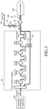
- Fig. 1 is an example of a configuration diagram showing a configuration of a hydrogen gas supply system of a hydrogen station according to an embodiment 1.
- a hydrogen gas supply system 500 is disposed in a hydrogen station 102.
- the hydrogen gas supply system 500 includes a hydrogen production apparatus 300, a multi-stage accumulator 101, a dispenser 30 (measuring device), a compressor 40, an adsorption column 70, an adsorption column control valve system 110, and a control circuit 100.
- An example of the hydrogen gas supply apparatus which supplies hydrogen gas to the multi-stage accumulator 101 and/or the dispenser 30 is configured by the compressor 40, the adsorption column 70, the adsorption column control valve system 110, pipes connecting those, etc.
- FIG. 1 shows an example of the on-site ST, where the hydrogen production apparatus 300 is disposed in the hydrogen station 102.
- the hydrogen production apparatus 300 is disposed in the hydrogen station 102.
- a configuration (off-site ST) is also preferable where high purity hydrogen gas produced at another site is carried into the hydrogen station 102 by a hydrogen trailer, and temporarily accumulated in a curdle or intermediate accumulator (not shown).
- the multi-stage accumulator 101 is composed of a plurality of pressure accumulators 10, 12, and 14.
- the three accumulators 10, 12, and 14 configure the multi-stage accumulator 101.
- the pressure accumulator 10 functions as a 1st bank having a low use lower limit pressure.
- the pressure accumulator 12 functions as a 2nd bank having an intermediate use lower limit pressure, for example.
- the pressure accumulator 14 functions as a 3rd bank having a high use lower limit pressure, for example.
- the pressure accumulators used as the 1st to 3rd banks are interchanged as needed.
- the suction side of the compressor 40 is connected by a pipe to the discharge side of the hydrogen production apparatus 300 via a valve 328.
- the adsorption column 70 is arranged between the discharge port of the compressor 40 and the multi-stage accumulator 101.
- an adsorbent for adsorbing impurities in the hydrogen gas discharged from the compressor 40 is disposed.
- the adsorbent it is preferable to use the one that has a high adsorption capacity for sulfur and halogen generated from component parts and the like of the compressor 40, and, for example, activated carbon, etc. can be used.
- the adsorbent is not limited to the one formed from one layer, and may be from a plurality of layers of different kinds.
- the adsorption column control valve system 110 is disposed at the gas inlet/outlet port side of the adsorption column 70, being at the discharge side of the compressor 40.
- the adsorption column control valve system 110 is composed of a plurality of valves 71, 72, and 73 (a plurality of valves) which can seal the adsorption column 70.
- the discharge side of the compressor 40 is connected by a pipe 76 to the gas inlet side of the adsorption column 70 via a shutoff valve 71 (the first valve) of the adsorption column control valve system 110.
- the gas outlet side (downstream side) of the adsorption column 70 is connected by a pipe to the multi-stage accumulator 101 side and/or the dispenser 30 side via the shutoff valve 72 of the adsorption column control valve system 110.
- a vent line 90 (vent pipe) branches from between the shutoff valve 71, which is disposed between the discharge port of the compressor 40 and the gas inlet port of the adsorption column 70, and the gas inlet port of the adsorption column 70.
- the shutoff valve 73 the second valve of the adsorption column control valve system 110 is disposed.
- the downstream side of the adsorption column 70 is connected by a pipe to the pressure accumulator 10 via the shutoff valve 72 and a valve 21. Similarly, the downstream side of the adsorption column 70 is connected by a pipe to the pressure accumulator 12 via the shutoff valve 72 and a valve 23. Similarly, the downstream side of the adsorption column 70 is connected by a pipe to the pressure accumulator 14 via the shutoff valve 72 and a valve 25. Similarly, the downstream side of the adsorption column 70 is connected by a pipe to the dispenser 30 via the shutoff valve 72 and a valve 28.
- the pressure accumulator 10 is connected by a pipe to the dispenser 30 via a valve 22.
- the pressure accumulator 12 is connected by a pipe to the dispenser 30 via a valve 24.
- the pressure accumulator 14 is connected by a pipe to the dispenser 30 via a valve 26.
- the discharge pressure of the hydrogen production apparatus 300 is measured by a manometer 318.
- the pressure in the pressure accumulator 10 is measured by a manometer 11.
- the pressure in the pressure accumulator 12 is measured by a manometer 13.
- the pressure in the pressure accumulator 14 is measured by a manometer 15.
- the dispenser 30 there are disposed a flow rate adjustment valve 29, a flowmeter 27, a cooler 32 (precooler), and a manometer 17.
- the flow rate of the hydrogen gas supplied from the multi-stage accumulator 101 or the compressor 40 is measured by the flowmeter 27, and adjusted by the flow rate adjustment valve 29.
- the hydrogen gas is cooled to a predetermined temperature (e.g., -40°C) by the cooler 32.
- the dispenser 30 fills a fuel tank 202 mounted on an FCV 200, which is a fuel cell vehicle powered by hydrogen gas, with the cooled hydrogen gas using, for example, a differential pressure.
- the outlet pressure (outlet pressure for filling fuel) at the outlet for filling hydrogen gas to be filled in the FCV 200 from the dispenser 30 is measured by the manometer 17.
- a control circuit 34 is disposed inside or close to the dispenser 30, and configured to be communicable with an on-board device 204 in the FCV 200 (fuel cell vehicle powered by hydrogen gas) having arriving at the hydrogen station 102.
- the control circuit 34 is configured to be radio communicable using infrared rays.
- Hydrogen gas serving as a fuel supplied from the dispenser 30 is injected through the receiving port (receptacle) into the fuel tank 202 of the FCV 200 via a fuel passage.
- the pressure and temperature in the fuel tank 202 are measured by a manometer 206 and a thermometer 205 arranged inside the fuel tank 202 or at the fuel passage.
- the hydrogen gas produced by the hydrogen production apparatus 300 is supplied in a low-pressure (e.g., 0.6 MPa) state to the suction side of the compressor 40. Therefore, the first side pressure P IN at the suction side of the compressor 40 is a low pressure at normal times. Under the control of the control circuit 100, the compressor 40 supplies the hydrogen gas supplied at a low pressure from the hydrogen production apparatus 300 to the pressure accumulators 10, 12, and 14 of the multi-stage accumulator 101 while compressing it.
- a low-pressure e.g., 0.6 MPa
- the compressor 40 may directly supply the hydrogen gas, supplied at a low pressure from the hydrogen production apparatus 300, to the FCV 200 while compressing it via the dispenser 30.
- the compressor 40 compresses hydrogen gas and supplies it to the pressure accumulator side which accumulates hydrogen gas. Specifically, the compressor 40 compresses hydrogen gas until the inside of each of the pressure accumulators 10, 12, and 14 of the multi-stage accumulator 101 becomes a predetermined high pressure (e.g., 82 MPa or more) . In other words, the compressor 40 performs compression until a second side pressure P OUT at the discharge side becomes a predetermined high pressure (e.g., 82 MPa).
- Which of the pressure accumulators 10, 12, 14, and the dispenser 30 is to be a hydrogen gas supply party of the compressor 40 may be determined by controlling, by the control circuit 100, opening/closing of the corresponding valves 21, 23, 25, and 28 disposed in the respective pipes. Alternatively, it may be controlled to supply the hydrogen gas to two or more pressure accumulators at the same time.
- the above-stated example describes the case where the pressure P IN for supplying hydrogen gas to the suction side of the compressor 40 is reduction-controlled to a predetermined low pressure (e.g., 0.6 MPa) .
- a predetermined low pressure e.g., 0.6 MPa
- Hydrogen gas in a pressure state higher than the predetermined low pressure e.g., 0.6 MPa
- a high pressure compressor which can variably change the pressure P IN (first side pressure) at the suction side is employed as the compressor 40.
- the hydrogen gas accumulated in the multi-stage accumulator 101 is cooled by the cooler 32 in the dispenser 30, and supplied from the dispenser 30 to the FCV 200 arriving at the hydrogen station 102.
- Fig. 2 is a configuration diagram showing an example of an internal structure of the control circuit 100 according to the embodiment 1.
- the control circuit 100 functions as a control apparatus.
- a communication control circuit 50 in the control circuit 100, there are disposed a communication control circuit 50, a memory 51, a receiving unit 52, an end pressure calculation unit 54, a flow planning unit 56, a system control unit 58, a pressure recovery control unit 61, a supply control unit 63, a pressure receiving unit 66, an HPU control unit 67, and storage devices 80, 82, and 84, such as magnetic disk drives.
- the pressure recovery control unit 61 includes a valve control unit 60 and a compressor control unit 62.
- the supply control unit 63 includes a dispenser control unit 64 and a valve control unit 65.
- Each of the “units” such as the receiving unit 52, the end pressure calculation unit 54, the flow planning unit 56, the system control unit 58, the pressure recovery control unit 61 (the valve control unit 60, the compressor control unit 62), the supply control unit 63 (the dispenser control unit 64, the valve control unit 65), the pressure receiving unit 66, and the HPU control unit 67 includes processing circuitry.
- the processing circuitry includes an electric circuit, a computer, a processor, a circuit board, a semiconductor device, or the like.
- a CPU Central Processing Unit
- FPGA Field-Programmable Gate Array
- ASIC Application Specific Integrated Circuit
- common processing circuitry may be used for each unit.
- different processing circuitry may be used for different processing circuitry.
- Input data required in the receiving unit 52, the end pressure calculation unit 54, the flow planning unit 56, the system control unit 58, the pressure recovery control unit 61 (the valve control unit 60, the compressor control unit 62), the supply control unit 63 (the dispenser control unit 64, the valve control unit 65), the pressure receiving unit 66, and the HPU control unit 67, or calculated results are stored in the memory 51 each time.
- a conversion table 81 which shows correlation among FCV information, such as the pressure, temperature, and volume of the fuel tank 202 mounted on the FCV 200, a remaining hydrogen gas amount calculated based on the FCV information, and filling information, such as a final pressure and a final temperature to be filled in the fuel tank 202.
- FCV information such as the pressure, temperature, and volume of the fuel tank 202 mounted on the FCV 200
- filling information such as a final pressure and a final temperature to be filled in the fuel tank 202.
- a correction table 83 for correcting results obtained from the conversion table 81 is stored.
- the compressor 40 compresses the hydrogen gas having been refined to high purity by the hydrogen production apparatus 300, even if impurities such as sulfur and halogen generated from component parts and the like of the compressor 40 are mixed in the hydrogen gas, the impurities can be removed by the adsorption column 70 disposed at the downstream side of the compressor 40, and in addition to this, it is possible, using the adsorption column control valve system 110, to inhibit the impurities having been adsorbed by the adsorbent in the adsorption column 70 from desorbing and diffusing to the compressor 40 side (the first side) . Therefore, it is possible to inhibit the quality of hydrogen gas to be supplied to the FCV, etc. from becoming out of specification (e.g., ISO standards).
- Fig. 3 is a configuration diagram showing an example of an internal structure of a compressor and an example of a structure of an adsorption column control valve system according to the embodiment 1.
- descriptions of the structure from the hydrogen production apparatus 300 to the suction port of the compressor 40, and the structure from the shutoff valve 72 to the multi-stage accumulator 101 (and dispenser 30) are omitted.
- the example of Fig. 3 shows, as the compressor 40, a multi-stage compressor equipped with a five-stage compression mechanism. A cooler for cooling compressed hydrogen gas is individually disposed between each stage of the compression mechanism in the compressor 40. Moreover, a snapper is disposed at the suction side of the first stage of the compression mechanism.
- the snapper functions as an accumulation tank (buffer) for mitigating pulsation of the hydrogen gas supplied from the hydrogen production apparatus 300.
- an orifice 91 throttling mechanism
- vent line 90 vent pipe
- a rapid pressure change due to opening of the vent line 90 can be reduced by the orifice 91.
- a decompression pipe 42 which connects the discharge side of the last stage compression mechanism and the snapper at the suction side of the first stage compression mechanism of the compressor 40, is connected via a flow rate adjustment valve 41.
- Fig. 4 is a flowchart showing main steps of an example of a hydrogen gas supply method according to the embodiment 1.
- the hydrogen gas supply method of the embodiment 1 executes a series of steps: an FCV filling step (102), a pressure accumulation step (S104), an adsorption column sealing control step (S120), a compressor suspension and HPU idling operation step (S122), and an in-compressor decompression step (S124).
- the pressure accumulation step (S104) executes a series of steps as internal steps: a compressor operation and HPU rated operation step (S106), a valve control step (S108), an adsorption step (S110), and a determination step (S112).
- FCV filling step (102) hydrogen gas is supplied to the FCV 200, and the fuel tank 202 in the FCV 200 is filled with the hydrogen gas.
- a specified pressure e.g., 82 MPa
- FCV 200 arrives at the hydrogen station 102, a worker of the hydrogen station 102 or a user of the FCV 200 connects (fits) a nozzle 44 of the dispenser 30 to the receiving port (receptacle) of the fuel tank 202 of the FCV 200, and fixes the nozzle 44.
- FCV 200 arrives at the hydrogen station 102, and the user or a worker of the hydrogen station 102 connects and fixes the nozzle 44 of the dispenser 30 to the receiving port (receptacle) of the fuel tank 202 of the FCV 200, a communication between the on-board device 204 and the control circuit 34 (repeater) is established.
- FCV information such as the present pressure and temperature of the fuel tank 202, and the volume of the fuel tank 202 is output (transmitted) in real time from the on-board device 204.
- the FCV information is relayed by the control circuit 34 and transmitted to the control circuit 100.
- the receiving unit 52 receives the FCV information via the communication control circuit 50.
- the FCV information is monitored at all times or at predetermined sampling intervals (e.g., 10 msec to several seconds) .
- the received FCV information is stored in the storage device 80 together with receiving time information.
- the end pressure calculation unit 54 reads the conversion table 81 from the storage device 80, and calculates and estimates a final pressure PF corresponding to a received pressure Pa and temperature Ti of the fuel tank 202 at the initial reception time, a volume V of the fuel tank 202, and an outside air temperature T'. Moreover, the end pressure calculation unit 54 reads the correction table 83 from the storage device 80, and corrects a numerical value obtained from the conversion table 81 as necessary. If there is a large error in an obtained result based on only data of the conversion table 81, the correction table 83 may be provided on the basis of a result obtained by an experiment, a simulation or the like. The calculated final pressure PF is output to the system control unit 58.
- the flow planning unit 56 creates, using the multi-stage accumulator 101, a filling control flow plan for performing differential pressure supplying (filling) of hydrogen gas to the fuel tank 202 of the FCV 200.
- the flow planning unit 56 creates a plan of a filling control flow which includes a selection of the accumulator (selecting from the pressure accumulators 10, 12, and 14) and a switching timing of the multi-stage accumulator 101 in order to make the pressure in the fuel tank 202 be the final pressure PF.
- Control data of the created filling control flow plan is temporarily stored in the storage device 82.
- the flow planning unit 56 sets a pressure increase rate depending on the outside temperature, and calculates a filling speed corresponding to the pressure increase rate.
- the flow planning unit 56 calculates a filling speed corresponding to the pressure increase rate depending on an outside temperature.
- the pressure increase rate determined depending on an outside temperature is beforehand included in the data of the conversion table 81.
- the filling control flow is planned on these conditions, and a time t (end time 1) (reaching time) from starting filling to reaching the final pressure PF is obtained.
- the fuel tank 202 mounted on the FCV 200 is filled with hydrogen gas from the dispenser 30 (measuring device). Specifically, it operates as follows:
- Fig. 5 is a diagram illustrating a filling method in a case of performing differential pressure filling of hydrogen fuel by using a multi-stage accumulator according to the embodiment 1.
- the ordinate axis indicates a pressure and the abscissa axis indicates a time.
- the pressures in the accumulators 10, 12, and 14 of the multi-stage accumulator 101 are generally accumulated in advance at the same pressure P0 (e.g., 82 MPa).
- the fuel tank 202 of the FCV 200 arriving at the hydrogen station 102 has a pressure Pa. It will be described where filling the fuel tank 202 of the FCV 200 starts from the state described above.
- filling the fuel tank 202 starts from the 1st bank, for example, the pressure accumulator 10. Specifically, it operates as follows: Under the control of the system control unit 58, the supply control unit 63 controls the supply unit 106 to supply the hydrogen fuel from the pressure accumulator 10 into the fuel tank 202 of the FCV 200. Specifically, the system control unit 58 controls the dispenser control unit 64 and the valve control unit 65. The dispenser control unit 64 communicates with the control circuit 34 of the dispenser 30 via the communication control circuit 50, and controls the operation of the dispenser 30. Specifically, first, the control circuit 43 adjusts the opening degree of the flow rate adjustment valve 29 in the dispenser 30 so that the filling speed may be a calculated filling speed M.
- the valve control unit 65 outputs control signals to the valves 22, 24, and 26 via the communication control circuit 50, and controls opening/closing of each valve. Specifically, the valve 22 is opened, and the valves 24 and 26 are kept in a state of closed. Thereby, the hydrogen fuel is supplied from the pressure accumulator 10 to the fuel tank 202.
- the hydrogen fuel accumulated in the pressure accumulator 10 moves toward the fuel tank 202 side at an adjusted filling speed, and the pressure in the fuel tank 202 gradually increases as shown by a dotted line Pt.
- the pressure (the graph indicated by "1st") of the pressure accumulator 10 gradually decreases.
- the accumulator to be used is switched from the pressure accumulator 10 to the 2nd bank, for example, the pressure accumulator 12.
- the valve control unit 65 outputs a control signal to the valves 22, 24, and 26 via the communication control circuit 50, and controls opening/closing of each valve.
- the valve 22 is closed, the valve 24 is opened, and the valve 26 is kept in a state of closed.
- the hydrogen fuel accumulated in the pressure accumulator 12 moves toward the fuel tank 202 side at a filling speed similarly adjusted, and the pressure in the fuel tank 202 gradually increases as indicated by the dotted line Pt.
- the pressure (the graph indicated by "2nd") of the pressure accumulator 12 gradually decreases.
- the accumulator to be used is switched from the pressure accumulator 12 to the 3rd bank, for example, the pressure accumulator 14.
- the valve control unit 65 outputs control signals to the valves 22, 24, and 26 via the communication control circuit 50, and controls opening/closing of each valve. Specifically, the valve 24 is closed, the valve 26 is opened, and the valve 22 is kept in a state of closed. Thereby, since the differential pressure between the pressure accumulator 14 and the fuel tank 202 is large, the state in which the filling speed is high can be maintained.
- the hydrogen fuel accumulated in the pressure accumulator 14 moves toward the fuel tank 202 side at an adjusted filling speed, and the pressure in the fuel tank 202 gradually increases as shown by the dotted line Pt.
- the pressure (the graph indicated by "3rd") in the pressure accumulator 14 gradually decreases.
- the accumulator 14 serving as the 3rd bank the filling is performed until the pressure in the fuel tank 202 reaches a calculated final pressure PF (e.g., 65 to 81 MPa).
- filling the fuel tank 202 with the hydrogen gas is performed in order from the 1st bank.
- the above example describes the case where the pressure P1 of the fuel tank 202 of the FCV 200 arriving at the hydrogen station 102 is sufficiently lower than the level of the use lower limit pressure of the pressure accumulator 10 serving as a preset low pressure bank.
- the case is described where it is sufficiently low such as 1/2 or less of the one at the full filling (filling up) time.
- the three accumulators 10, 12, and 14, for example are required.
- the pressure in the fuel tank 202 of the FCV 200 arriving at the hydrogen station 102 is not limited to being sufficiently low.
- the pressure in the fuel tank 202 is higher than, for example, 1/2 of the one at the full filling (filling up) time, two accumulators 10 and 12, for example, may be sufficient.
- the pressure in the fuel tank 202 is high, one accumulator 10, for example, may be sufficient. In any case, the accumulator to be used is switched between the pressure accumulators 10, 12, and 14.
- the nozzle 44 of the dispenser 30 is removed from the receiving port (receptacle) of the fuel tank 202 of the FCV 200, and after paying a fee corresponding to the filling amount, for example, the user leaves the hydrogen station 102.
- the compressor 40 compresses hydrogen gas and supplies it the pressure accumulator side which accumulates the hydrogen gas. Specifically, it operates as follows:
- the multi-stage accumulator 101 starts filling hydrogen to the FCV 200.
- the hydrogen production apparatus 300 shifts from an idling operation to a rated operation (e.g., 100% load operation) under the control of the HPU control unit 67, and increases the amount of hydrogen gas produced.
- the valve control circuit 60 makes an open valve 319 close, and the valve 328 open. Then, under the control of the compressor control unit 62, the compressor 40 starts the operation, and compresses and discharges the low-pressure hydrogen gas supplied from the hydrogen production apparatus 300.
- valve control circuit 60 controls the adsorption column control valve system 110 so that compressed hydrogen gas may be supplied to the pressure accumulator side.
- Fig. 6 is a diagram illustrating operations of the adsorption column control valve system at the time of the pressure accumulation step according to the embodiment 1.
- the valve control circuit 60 controls the shutoff valve 73 to be closed, and the shutoff valves 71 and 72 to be opened from closed.
- adsorption step (S110) using the adsorption column 70with an adsorbent arranged, impurities in the hydrogen gas discharged from the compressor 40 are adsorbed onto the adsorbent in the adsorption column 70. Then, the hydrogen gas of high purity because of the impurities having been adsorbed is supplied to the multi-stage accumulator 101 side from the gas outlet of the adsorption column 70.
- valve control unit 60 opens, for example, the valve 25 from the state where the valves 21, 22, 23, 24, 25, 26, and 28 are closed.
- hydrogen gas which has been compressed from a low pressure (e.g., 0.6 MPa) by the operation of the compressor 40 and whose impurities have been adsorbed by the adsorbent in the adsorption column 70, is charged into the accumulator 14 until the pressure in the accumulator 14 reaches a predetermined pressure P0 (e.g., 82 MPa). By this, the pressure in the accumulator 14 is accumulated (recovered).
- a low pressure e.g., 0.6 MPa
- valve control unit 60 closes the valve 25, and instead opens the valve 23.
- valve control unit 60 closes the valve 23, and instead opens the valve 21.
- the system control unit 58 determines whether the pressures of all the accumulators 10, 12, and 14 of the multi-stage accumulator 101 have been accumulated to a predetermined pressure P0 (e.g., 82 MPa) . If not having been accumulated up to the predetermined pressure P0 (e.g., 82 MPa) yet, the pressure accumulation is continued. When having been accumulated up to the predetermined pressure P0 (e.g., 82 MPa), it proceeds to the next step. Although the case where pressure accumulation is continued until the pressures of all the accumulators 10, 12, and 14 of the multi-stage accumulator 101 have been sufficiently accumulated is described here as an example, it is not limited thereto.
- the pressure accumulation step (S104) may be ended at the stage where pressure accumulation of any one of the accumulators 10, 12, and 14 has been sufficiently performed.
- the pressures of the accumulators 10, 12, and 14 can be accumulated up to the predetermined pressure P0 (e.g., 82 MPa). Thereby, preparation for differential pressure filling to the FCV 200 by the multi-stage accumulator 101 is performed.
- P0 e.g., 82 MPa
- the space inside the adsorption column 70 is sealed so that the inside of the adsorption column 70 may be maintained at a high pressure by the compressed hydrogen gas.
- Fig. 7 is a diagram illustrating operations of the adsorption column control valve system at the time of the adsorption column sealing control step according to the embodiment 1.
- the valve control circuit 60 controls all the shutoff valves 71, 72, and 73 configuring the adsorption column control valve system 110 to be closed, and seals the space inside the adsorption column 70 so that the inside of the adsorption column 70 may be maintained at a high pressure by the compressed hydrogen gas.
- the hydrogen production apparatus 300 shifts from a rated operation (e.g., 100% load operation) to an idling operation (e.g., 30% load operation) under the control of the HPU control unit 67, thereby reducing the amount of hydrogen gas produced.
- the the valve control circuit 60 controls the open valve 319 to be open from closed, and the valve 328 to be closed from open, thereby stopping supplying hydrogen gas to the compressor 40.
- a small amount of hydrogen gas produced by the idling operation is discharged to the air because the open valve 319 has become open.
- the operation of the compressor 40 is suspended (stopped). Therefore, while the operation of the compressor 40 is completely stopped, the shutoff valves 71 and 72 are controlled to be closed.
- the in-compressor decompression step (S124) under the control of the compressor control unit 62, while the flow rate adjustment valve 41 adjusts the flow rate at a predetermined opening degree, the pressure inside the compressor 40 is depressurized down to the pressure at the suction side of the compressor 40 via the decompression pipe 42.
- a rapid pressure change can be inhibited, thereby inhibiting damage to component parts of the adsorption column 70, etc., or breakage, etc. of the adsorbent such as activated carbon.
- FCV 200 When the next FCV 200 arrives at the hydrogen station 102, it returns to the FCV filling step (102), and each step from the FCV filling step (102) to the in-compressor decompression step (S124) is repeated.
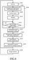
- Fig. 8 is a flowchart showing main steps of another example of the hydrogen gas supply method according to the embodiment 1.
- the hydrogen gas supply method in the embodiment 1 is the same as that of Fig. 4 except that an adsorption column decompression/regeneration step (S126) and a purge control step (S128) are added after the in-compressor decompression step (S124) of Fig. 4 . Therefore, in Fig.
- the hydrogen gas supply method executes a series of steps: the FCV filling step (102), the pressure accumulation step (S104), the adsorption column sealing control step (S120), the compressor suspension and HPU idling operation step (S122), the in-compressor decompression step (S124), the adsorption column decompression/regeneration step (S126), and the purge control step (S128) .
- the pressure accumulation step (S104) executes a series of steps as internal steps: the compressor operation and HPU rated operation step (S106), the valve control step (S108), the adsorption step (S110), and the determination step (S112) .
- the hydrogen purge step (S128) does not need to be executed each time. For example, with respect to the cycle of the respective steps in Fig. 8 , the hydrogen purge step (S128) may be executed once for several cycles. Needless to say, it may be carried out each time.
- the adsorption column decompression/regeneration step (S126), by opening the shutoff valve 73 from the state where the space inside the adsorption column 70 is sealed by a plurality of shutoff valves 71, 72, and 73 of the adsorption column control valve system 110, the pressure inside the adsorption column 70 is depressurized from a high pressure to a low pressure, and impurities desorbed from the adsorbent are discharged to the vent line 90.
- Fig. 9 is a diagram illustrating operations of an adsorption column control valve system at the time of the adsorption column decompression/regeneration step according to the embodiment 1.
- the valve control unit 60 opens the shutoff valve 73 from the state where the shutoff valves 71, 72, and 73 are closed. Thereby, the hydrogen gas enclosed in the adsorption column 70 is discharged through the vent line 90.
- the orifice 91 is disposed in the vent line 90, a rapid pressure change can be inhibited, thereby inhibiting damage to component parts of the adsorption column 70, etc., or breakage, etc. of the adsorbent such as activated carbon.
- the adsorption column 70 Because the pressure inside the adsorption column 70 is depressurized, adsorbed impurities desorb from the adsorbent. Then, the impurities are discharged along the flow of the internal hydrogen gas through the vent line 90. Thereby, the adsorbent can be regenerated (refreshed) . Therefore, even when the adsorption column 70 is miniaturized and the amount of adsorbent on board is small, the adsorption performance of the adsorbent can be extended.
- the control apparatus 100 controls to open the shutoff valve 71, and supply the hydrogen gas supplied from the hydrogen production apparatus 300 through the compressor 40 being stopped to the adsorption column 70.
- the hydrogen gas supplied from the hydrogen production apparatus 300 through the compressor 40 being stopped is introduced as a purge gas to the adsorption column 70.
- a purge gas is introduced into the adsorption column 70.
- Fig. 10 is a diagram illustrating operations of an adsorption column control valve system at the time of the purge control step according to the embodiment 1.
- the hydrogen production apparatus 300 under an idling operation high-purity hydrogen gas is continued to be produced although the production amount is small.
- the hydrogen gas produced by the hydrogen production apparatus 300 under an idling operation is not supplied to the compressor 40, but is discharged from the vent line via the open valve 319.
- the valve control unit 60 controls to open the shutoff valves 71 and 73, close the open valve 319, and open the valve 328.
- the hydrogen gas produced by the hydrogen production apparatus 300 under an idling operation is supplied into the adsorption column 70 through the compressor 40 being stopped, and is discharged from the vent line 90.
- this hydrogen gas as a purge gas to be introduced into the adsorption column 70, regeneration of the adsorbent can be accelerated.
- impurities such as sulfur and halogen are generated due to sliding of the piston ring and the like which is generated by driving a piston during the operation of the compressor 40, for example. Accordingly, it is assumed that impurities such as sulfur and halogen are not generated while the compressor 40 is suspended (stopped), and therefore, hydrogen gas maintaining high purity can be used as a purge gas.
- hydrogen gas conventionally discarded can be utilized.
- FCV 200 When the next FCV 200 arrives at the hydrogen station 102, it returns to the FCV filling step (102), and each step from the FCV filling step (102) to the adsorption column decompression/regeneration step (S126) (or the purge control step (S128)) is repeated.
- the embodiment 1 it is possible to inhibit impurities of hydrogen gas, having been adsorbed by the adsorbent disposed at the downstream side of the compressor 40, from diffusing to the compressor 40 side. Further, the adsorbent can be regenerated, and the adsorption performance of the adsorbent can be extended. Therefore, it is also possible to further miniaturize the adsorption column 70.
- the present invention relates to a hydrogen gas supply apparatus and a hydrogen gas supply method, and can be applied to, for example, a hydrogen gas supply apparatus and hydrogen gas supply method arranged at a hydrogen station.
Landscapes
- Engineering & Computer Science (AREA)
- Chemical & Material Sciences (AREA)
- Mechanical Engineering (AREA)
- General Engineering & Computer Science (AREA)
- Organic Chemistry (AREA)
- Analytical Chemistry (AREA)
- General Chemical & Material Sciences (AREA)
- Oil, Petroleum & Natural Gas (AREA)
- Chemical Kinetics & Catalysis (AREA)
- Combustion & Propulsion (AREA)
- Inorganic Chemistry (AREA)
- Filling Or Discharging Of Gas Storage Vessels (AREA)
- Separation Of Gases By Adsorption (AREA)
- Hydrogen, Water And Hydrids (AREA)
- Fuel Cell (AREA)
- Compressor (AREA)
Abstract
Description
- This application is based upon and claims the benefit of priority from
Japanese Patent Application No. 2019-064192 filed on March 28, 2019 - The present invention relates to a hydrogen gas supply apparatus and a hydrogen gas supply method, and, for example, to a hydrogen gas supply apparatus and hydrogen gas supply method arranged at a hydrogen station.
- As fuel for vehicles, in addition to conventional fuel oils such as gasoline, hydrogen gas has recently attracted attention as a clean energy source . Correspondingly, fuel cell vehicles (FCVs) powered by the hydrogen gas have been developed. As hydrogen stations for FCVs, there are a hydrogen production base such as a hydrogen shipping center and an on-site hydrogen station (hereafter referred to as an on-site ST), and an off-site hydrogen station (hereafter referred to as an off-site ST) which receives and sells hydrogen from the hydrogen production base (hydrogen shipping center, on-site ST, etc.). Hydrogen gas is produced by an HPU (Hydrogen Product Unit), etc. At hydrogen stations, in order to rapidly fill FCVs with hydrogen gas, there are disposed a compressor for compressing hydrogen gas to a high pressure, and a plurality of pressure accumulators (multi-stage accumulator) for accumulating the hydrogen gas compressed to a high pressure by the compressor. In such hydrogen stations, hydrogen gas is rapidly charged from the pressure accumulator into the fuel tank by performing filling while suitably switching the pressure accumulator to be used such that the differential pressure between the pressure inside the pressure accumulator and the pressure in the fuel tank of the FCV is maintained large.
- Here, there has been a problem that, in compressing the hydrogen gas having been refined to high purity as a fuel for FCV by a compressor, impurities such as sulfur, halogen generated from component parts and the like of the compressor mix with the hydrogen gas, thereby making the quality of the hydrogen gas out of specification. In response to this problem, it is now examined to dispose an adsorption column, with an adsorbent arranged, at the downstream side of the compressor and to remove the impurities. However, it has been a problem that since the operation of the compressor is stopped after a specified amount of hydrogen has been charged into the pressure accumulator, the inside of the compressor is depressurized down to the pressure at the suction side, and thus the impurities having been adsorbed by the adsorbent desorb and diffuse toward the compressor side (the first side).
- There is here disclosed a method for making impurities adsorbed on an adsorbent in the process of hydrogen production (e.g., refer to Patent Literature 1).
- Patent Literature 1:
JP-A-2011-167629 - One aspect of the present invention provides an apparatus and method capable of inhibiting impurities of hydrogen gas adsorbed by an adsorbent disposed at the downstream side of the compressor from diffusing to the compressor side.
- According to one aspect of the present invention, a hydrogen gas supply apparatus, includes
- a compressor configured to compress hydrogen gas;
- a pressure accumulator configured to accumulate the hydrogen gas compressed by the compressor;
- an adsorption column disposed between the compressor and the pressure accumulator, and configured to include an adsorbent which adsorbs impurities mixed in the hydrogen gas discharged from the compressor;
- a first valve disposed in a first gas supply pipe between the compressor and the adsorption column;
- a second valve disposed in a second gas supply pipe between the adsorption column and the pressure accumulator; and
- a control apparatus configured to control to close the first valve and the second valve while an operation of the compressor is stopped.
- Further, it is preferable to further include a vent line configured to branch from between the first valve in the first gas supply pipe and the adsorption column, and a third valve disposed in the vent line, wherein the control apparatus controls, in a state where the first valve and the second valve are controlled to be closed, to open the third valve.
- Further, it is preferable to further include a hydrogen production apparatus configured to supply the hydrogen gas to the compressor, wherein the control apparatus controls, after a predetermined time has elapsed since the third valve was opened, to open the first valve, and supply the hydrogen gas, supplied from the hydrogen production apparatus through the compressor being stopped, to the adsorption column.
- Further, it is preferable that the adsorbent has an adsorption capacity for sulfur and halogen.
- According to another aspect of the present invention, a hydrogen gas supply method includes
- compressing hydrogen gas by a compressor;
- accumulating the hydrogen gas compressed by the compressor in a pressure accumulator;
- making, using an adsorption column which is disposed between the compressor and the pressure accumulator and includes an adsorbent, the adsorbent adsorb impurities mixed in the hydrogen gas discharged from the compressor; and
- controlling, while an operation of the compressor is stopped, to close a first valve disposed in a first gas supply pipe between the compressor and the adsorption column, and a second valve disposed in a second gas supply pipe between the adsorption column and the pressure accumulator.
- Further, it is preferable that controlling is performed, in a state where the first valve and the second valve are controlled to be closed, to open a third valve disposed in a vent line branching from between the first valve in the first gas supply pipe and the adsorption column.
- According to yet another aspect of the present invention, a hydrogen gas supply apparatus includes
- a compressor configured to compress hydrogen gas, and supply the hydrogen gas compressed to a pressure accumulator which accumulates the hydrogen gas;
- an adsorption column disposed between a discharge port of the compressor and the pressure accumulator, and configured to include an adsorbent for adsorbing impurities in the hydrogen gas discharged from the compressor; and
- a plurality of valves disposed at a gas inlet/outlet port side of the adsorption column, being at a discharge port side of the compressor, and configured to be able to seal the adsorption column, wherein
- a space in the adsorption column is sealed using the plurality of valves such that an inside of the adsorption column is maintained to have a high pressure by the hydrogen gas compressed, in a case where the compressor is stopped.
- Further, it is preferable to further include a vent line configured to branch between a first valve, which is one of the plurality of valves and disposed between a discharge port of the compressor and a gas inlet port of the adsorption column, and the gas inlet port of the adsorption column, wherein a second valve which is one of the plurality of valves is disposed in a middle of the vent line, and the inside of the adsorption column is depressurized from the high pressure to a low pressure, and impurities desorbed from the adsorbent are discharged to the vent line by opening the second valve from a state where the space in the adsorption column is sealed by the plurality of valves.
- Further, it is preferable that the hydrogen gas is supplied to the compressor from a hydrogen production apparatus, and the hydrogen gas supplied from the hydrogen production apparatus through the compressor being stopped is introduced as a purge gas to the adsorption column.
- Further, it is preferable that the impurities are those having been mixed in the compressor in a state where the compressor is stopped and the inside of the adsorption column has been depressurized to the low pressure, and further in a state where the first valve and the second valve are opened.
- According to yet another aspect of the present invention, a hydrogen gas supply method includes
- compressing hydrogen gas by a compressor, and supplying the hydrogen gas compressed to a side of a pressure accumulator which accumulates the hydrogen gas;
- adsorb impurities in the hydrogen gas discharged from the compressor, to an adsorbent by using an adsorption column which is disposed between a discharge port of the compressor and the pressure accumulator for accumulating the hydrogen gas and includes the adsorbent; and
- sealing a space in the adsorption column such that an inside of the adsorption column is maintained to have a high pressure by the hydrogen gas compressed, in a case where the compressor is stopped by using a plurality of valves which are disposed at a gas inlet/outlet port side of the adsorption column, being at a discharge port side of the compressor, and are able to seal the adsorption column.
- It is preferable that, by using a vent line branching between a first valve, which is one of the plurality of valves and disposed between the discharge port of the compressor and the gas inlet port of the adsorption column, and the gas inlet port of the adsorption column, and by using a second valve in the plurality of valves disposed in a middle of the vent line, performed are depressurizing the inside of the adsorption column from a high pressure to a low pressure, and discharging the impurities desorbed from the adsorbent to the vent line by opening the second valve from a state where the space in the adsorption column is sealed by the plurality of valves.
- According to one aspect of the present invention, it is possible to inhibit impurities of hydrogen gas adsorbed by the adsorbent disposed at the downstream side of the compressor from diffusing to the compressor side.
-
-
Fig. 1 is an example of a configuration diagram showing a configuration of a hydrogen gas supply system of a hydrogen station according to anembodiment 1. -
Fig. 2 is a configuration diagram showing an example of an internal structure of a control circuit according to theembodiment 1. -
Fig. 3 is a configuration diagram showing an example of an internal structure of a compressor and an example of a structure of an adsorption column control valve system according to theembodiment 1. -
Fig. 4 is a flowchart showing main steps of an example of a hydrogen gas supply method according to theembodiment 1. -
Fig. 5 is a diagram illustrating a filling method in a case of performing differential pressure filling of hydrogen fuel by using a multi-stage accumulator according to theembodiment 1. -
Fig. 6 is a diagram illustrating operations of an adsorption column control valve system at the time of a pressure accumulation step according to theembodiment 1. -
Fig. 7 is a diagram illustrating operations of an adsorption column control valve system at the time of an adsorption column sealing control step according to theembodiment 1. -
Fig. 8 is a flowchart showing main steps of another example of the hydrogen gas supply method according to theembodiment 1. -
Fig. 9 is a diagram illustrating operations of an adsorption column control valve system at the time of an adsorption column decompression/regeneration step according to theembodiment 1. -
Fig. 10 is a diagram illustrating operations of an adsorption column control valve system at the time of a purge control step according to theembodiment 1. -
Fig. 1 is an example of a configuration diagram showing a configuration of a hydrogen gas supply system of a hydrogen station according to anembodiment 1. InFig. 1 , a hydrogengas supply system 500 is disposed in ahydrogen station 102. The hydrogengas supply system 500 includes ahydrogen production apparatus 300, amulti-stage accumulator 101, a dispenser 30 (measuring device), acompressor 40, anadsorption column 70, an adsorption columncontrol valve system 110, and acontrol circuit 100. An example of the hydrogen gas supply apparatus which supplies hydrogen gas to themulti-stage accumulator 101 and/or thedispenser 30 is configured by thecompressor 40, theadsorption column 70, the adsorption columncontrol valve system 110, pipes connecting those, etc. The example ofFig. 1 shows an example of the on-site ST, where thehydrogen production apparatus 300 is disposed in thehydrogen station 102. However, it is not limited thereto. A configuration (off-site ST) is also preferable where high purity hydrogen gas produced at another site is carried into thehydrogen station 102 by a hydrogen trailer, and temporarily accumulated in a curdle or intermediate accumulator (not shown). - The
multi-stage accumulator 101 is composed of a plurality ofpressure accumulators Fig. 1 , the threeaccumulators multi-stage accumulator 101. In the case ofFig. 1 , for example, thepressure accumulator 10 functions as a 1st bank having a low use lower limit pressure. Thepressure accumulator 12 functions as a 2nd bank having an intermediate use lower limit pressure, for example. Thepressure accumulator 14 functions as a 3rd bank having a high use lower limit pressure, for example. However, it is not limited thereto. The pressure accumulators used as the 1st to 3rd banks are interchanged as needed. - Further, in
Fig. 1 , the suction side of thecompressor 40 is connected by a pipe to the discharge side of thehydrogen production apparatus 300 via a valve 328. - The
adsorption column 70 is arranged between the discharge port of thecompressor 40 and themulti-stage accumulator 101. In theadsorption column 70, an adsorbent for adsorbing impurities in the hydrogen gas discharged from thecompressor 40 is disposed. As the adsorbent, it is preferable to use the one that has a high adsorption capacity for sulfur and halogen generated from component parts and the like of thecompressor 40, and, for example, activated carbon, etc. can be used. The adsorbent is not limited to the one formed from one layer, and may be from a plurality of layers of different kinds. - The adsorption column
control valve system 110 is disposed at the gas inlet/outlet port side of theadsorption column 70, being at the discharge side of thecompressor 40. The adsorption columncontrol valve system 110 is composed of a plurality ofvalves adsorption column 70. The discharge side of thecompressor 40 is connected by apipe 76 to the gas inlet side of theadsorption column 70 via a shutoff valve 71 (the first valve) of the adsorption columncontrol valve system 110. The gas outlet side (downstream side) of theadsorption column 70 is connected by a pipe to themulti-stage accumulator 101 side and/or thedispenser 30 side via theshutoff valve 72 of the adsorption columncontrol valve system 110. A vent line 90 (vent pipe) branches from between theshutoff valve 71, which is disposed between the discharge port of thecompressor 40 and the gas inlet port of theadsorption column 70, and the gas inlet port of theadsorption column 70. In the middle of thevent line 90, the shutoff valve 73 (the second valve) of the adsorption columncontrol valve system 110 is disposed. - The downstream side of the
adsorption column 70 is connected by a pipe to thepressure accumulator 10 via theshutoff valve 72 and avalve 21. Similarly, the downstream side of theadsorption column 70 is connected by a pipe to thepressure accumulator 12 via theshutoff valve 72 and avalve 23. Similarly, the downstream side of theadsorption column 70 is connected by a pipe to thepressure accumulator 14 via theshutoff valve 72 and avalve 25. Similarly, the downstream side of theadsorption column 70 is connected by a pipe to thedispenser 30 via theshutoff valve 72 and avalve 28. - Further, the
pressure accumulator 10 is connected by a pipe to thedispenser 30 via avalve 22. Thepressure accumulator 12 is connected by a pipe to thedispenser 30 via avalve 24. Thepressure accumulator 14 is connected by a pipe to thedispenser 30 via avalve 26. - Further, the discharge pressure of the
hydrogen production apparatus 300 is measured by amanometer 318. The pressure in thepressure accumulator 10 is measured by amanometer 11. The pressure in thepressure accumulator 12 is measured by amanometer 13. The pressure in thepressure accumulator 14 is measured by amanometer 15. - In the
dispenser 30, there are disposed a flowrate adjustment valve 29, aflowmeter 27, a cooler 32 (precooler), and amanometer 17. The flow rate of the hydrogen gas supplied from themulti-stage accumulator 101 or thecompressor 40 is measured by theflowmeter 27, and adjusted by the flowrate adjustment valve 29. Then, the hydrogen gas is cooled to a predetermined temperature (e.g., -40°C) by the cooler 32. Thus, thedispenser 30 fills afuel tank 202 mounted on anFCV 200, which is a fuel cell vehicle powered by hydrogen gas, with the cooled hydrogen gas using, for example, a differential pressure. The outlet pressure (outlet pressure for filling fuel) at the outlet for filling hydrogen gas to be filled in theFCV 200 from thedispenser 30 is measured by themanometer 17. Further, acontrol circuit 34 is disposed inside or close to thedispenser 30, and configured to be communicable with an on-board device 204 in the FCV 200 (fuel cell vehicle powered by hydrogen gas) having arriving at thehydrogen station 102. For example, thecontrol circuit 34 is configured to be radio communicable using infrared rays. - Hydrogen gas serving as a fuel supplied from the
dispenser 30 is injected through the receiving port (receptacle) into thefuel tank 202 of theFCV 200 via a fuel passage. The pressure and temperature in thefuel tank 202 are measured by amanometer 206 and athermometer 205 arranged inside thefuel tank 202 or at the fuel passage. - The hydrogen gas produced by the
hydrogen production apparatus 300 is supplied in a low-pressure (e.g., 0.6 MPa) state to the suction side of thecompressor 40. Therefore, the first side pressure PIN at the suction side of thecompressor 40 is a low pressure at normal times. Under the control of thecontrol circuit 100, thecompressor 40 supplies the hydrogen gas supplied at a low pressure from thehydrogen production apparatus 300 to thepressure accumulators multi-stage accumulator 101 while compressing it. When the supply amount of hydrogen gas is insufficient in supplying it to theFCV 200 from themulti-stage accumulator 101, or when themulti-stage accumulator 101 is recovering pressure, thecompressor 40, under the control of thecontrol circuit 100, may directly supply the hydrogen gas, supplied at a low pressure from thehydrogen production apparatus 300, to theFCV 200 while compressing it via thedispenser 30. - The
compressor 40 compresses hydrogen gas and supplies it to the pressure accumulator side which accumulates hydrogen gas. Specifically, thecompressor 40 compresses hydrogen gas until the inside of each of thepressure accumulators multi-stage accumulator 101 becomes a predetermined high pressure (e.g., 82 MPa or more) . In other words, thecompressor 40 performs compression until a second side pressure POUT at the discharge side becomes a predetermined high pressure (e.g., 82 MPa). Which of thepressure accumulators dispenser 30 is to be a hydrogen gas supply party of thecompressor 40 may be determined by controlling, by thecontrol circuit 100, opening/closing of the correspondingvalves - The above-stated example describes the case where the pressure PIN for supplying hydrogen gas to the suction side of the
compressor 40 is reduction-controlled to a predetermined low pressure (e.g., 0.6 MPa) . However, it is not limited thereto. Hydrogen gas in a pressure state higher than the predetermined low pressure (e.g., 0.6 MPa) may be supplied to the suction side of thecompressor 40 so as to be compressed. In that case, not a reciprocating compressor which uses the pressure PIN (first side pressure) at the suction side at a fixed pressure (e.g., 0.6 MPa), but a high pressure compressor which can variably change the pressure PIN (first side pressure) at the suction side is employed as thecompressor 40. For example, it is preferable to use a multi-stage booster type compressor whose pressure PIN (first side pressure) at the suction side is, for example, 20 MPa or less. - The hydrogen gas accumulated in the
multi-stage accumulator 101 is cooled by the cooler 32 in thedispenser 30, and supplied from thedispenser 30 to theFCV 200 arriving at thehydrogen station 102. -
Fig. 2 is a configuration diagram showing an example of an internal structure of thecontrol circuit 100 according to theembodiment 1. Thecontrol circuit 100 functions as a control apparatus. InFig. 2 , in thecontrol circuit 100, there are disposed acommunication control circuit 50, amemory 51, a receivingunit 52, an endpressure calculation unit 54, aflow planning unit 56, asystem control unit 58, a pressurerecovery control unit 61, asupply control unit 63, apressure receiving unit 66, anHPU control unit 67, andstorage devices recovery control unit 61 includes avalve control unit 60 and acompressor control unit 62. Thesupply control unit 63 includes adispenser control unit 64 and avalve control unit 65. Each of the "units" such as the receivingunit 52, the endpressure calculation unit 54, theflow planning unit 56, thesystem control unit 58, the pressure recovery control unit 61 (thevalve control unit 60, the compressor control unit 62), the supply control unit 63 (thedispenser control unit 64, the valve control unit 65), thepressure receiving unit 66, and theHPU control unit 67 includes processing circuitry. The processing circuitry includes an electric circuit, a computer, a processor, a circuit board, a semiconductor device, or the like. As the processing circuitry, for example, a CPU (Central Processing Unit), an FPGA (Field-Programmable Gate Array) , or an ASIC (Application Specific Integrated Circuit) may be used. Further, for each unit, common processing circuitry (same processing circuitry) may be used. Alternatively, different processing circuitry (separate processing circuitry) may be used. Input data required in the receivingunit 52, the endpressure calculation unit 54, theflow planning unit 56, thesystem control unit 58, the pressure recovery control unit 61 (thevalve control unit 60, the compressor control unit 62), the supply control unit 63 (thedispenser control unit 64, the valve control unit 65), thepressure receiving unit 66, and theHPU control unit 67, or calculated results are stored in thememory 51 each time. - In the
storage device 80, there is stored a conversion table 81 which shows correlation among FCV information, such as the pressure, temperature, and volume of thefuel tank 202 mounted on theFCV 200, a remaining hydrogen gas amount calculated based on the FCV information, and filling information, such as a final pressure and a final temperature to be filled in thefuel tank 202. Moreover, in thestorage device 80, a correction table 83 for correcting results obtained from the conversion table 81 is stored. - In the hydrogen
gas supply system 500, when thecompressor 40 compresses the hydrogen gas having been refined to high purity by thehydrogen production apparatus 300, even if impurities such as sulfur and halogen generated from component parts and the like of thecompressor 40 are mixed in the hydrogen gas, the impurities can be removed by theadsorption column 70 disposed at the downstream side of thecompressor 40, and in addition to this, it is possible, using the adsorption columncontrol valve system 110, to inhibit the impurities having been adsorbed by the adsorbent in theadsorption column 70 from desorbing and diffusing to thecompressor 40 side (the first side) . Therefore, it is possible to inhibit the quality of hydrogen gas to be supplied to the FCV, etc. from becoming out of specification (e.g., ISO standards). -
Fig. 3 is a configuration diagram showing an example of an internal structure of a compressor and an example of a structure of an adsorption column control valve system according to theembodiment 1. InFig. 3 , descriptions of the structure from thehydrogen production apparatus 300 to the suction port of thecompressor 40, and the structure from theshutoff valve 72 to the multi-stage accumulator 101 (and dispenser 30) are omitted. The example ofFig. 3 shows, as thecompressor 40, a multi-stage compressor equipped with a five-stage compression mechanism. A cooler for cooling compressed hydrogen gas is individually disposed between each stage of the compression mechanism in thecompressor 40. Moreover, a snapper is disposed at the suction side of the first stage of the compression mechanism. The snapper functions as an accumulation tank (buffer) for mitigating pulsation of the hydrogen gas supplied from thehydrogen production apparatus 300. Further, an orifice 91 (throttling mechanism) is disposed in the middle of the vent line 90 (vent pipe) . A rapid pressure change due to opening of thevent line 90 can be reduced by theorifice 91. Further, in thecompressor 40, adecompression pipe 42, which connects the discharge side of the last stage compression mechanism and the snapper at the suction side of the first stage compression mechanism of thecompressor 40, is connected via a flowrate adjustment valve 41. -
Fig. 4 is a flowchart showing main steps of an example of a hydrogen gas supply method according to theembodiment 1. InFig. 4 , the hydrogen gas supply method of theembodiment 1 executes a series of steps: an FCV filling step (102), a pressure accumulation step (S104), an adsorption column sealing control step (S120), a compressor suspension and HPU idling operation step (S122), and an in-compressor decompression step (S124). The pressure accumulation step (S104) executes a series of steps as internal steps: a compressor operation and HPU rated operation step (S106), a valve control step (S108), an adsorption step (S110), and a determination step (S112). - In the FCV filling step (102), hydrogen gas is supplied to the
FCV 200, and thefuel tank 202 in theFCV 200 is filled with the hydrogen gas. Specifically, as an example, it operates as follows: Here, description is started from a state where hydrogen gas of a specified pressure (e.g., 82 MPa) is accumulated in themulti-stage compressor 101. - When the
FCV 200 arrives at thehydrogen station 102, a worker of thehydrogen station 102 or a user of theFCV 200 connects (fits) anozzle 44 of thedispenser 30 to the receiving port (receptacle) of thefuel tank 202 of theFCV 200, and fixes thenozzle 44. When theFCV 200 arrives at thehydrogen station 102, and the user or a worker of thehydrogen station 102 connects and fixes thenozzle 44 of thedispenser 30 to the receiving port (receptacle) of thefuel tank 202 of theFCV 200, a communication between the on-board device 204 and the control circuit 34 (repeater) is established. - Next, when the communication between the on-
board device 204 and thecontrol circuit 34 is established, FCV information such as the present pressure and temperature of thefuel tank 202, and the volume of thefuel tank 202 is output (transmitted) in real time from the on-board device 204. The FCV information is relayed by thecontrol circuit 34 and transmitted to thecontrol circuit 100. In thecontrol circuit 100, the receivingunit 52 receives the FCV information via thecommunication control circuit 50. While the communication between the on-board device 204 and thecontrol circuit 34 is established, the FCV information is monitored at all times or at predetermined sampling intervals (e.g., 10 msec to several seconds) . The received FCV information is stored in thestorage device 80 together with receiving time information. - The end
pressure calculation unit 54 reads the conversion table 81 from thestorage device 80, and calculates and estimates a final pressure PF corresponding to a received pressure Pa and temperature Ti of thefuel tank 202 at the initial reception time, a volume V of thefuel tank 202, and an outside air temperature T'. Moreover, the endpressure calculation unit 54 reads the correction table 83 from thestorage device 80, and corrects a numerical value obtained from the conversion table 81 as necessary. If there is a large error in an obtained result based on only data of the conversion table 81, the correction table 83 may be provided on the basis of a result obtained by an experiment, a simulation or the like. The calculated final pressure PF is output to thesystem control unit 58. - Next, the
flow planning unit 56 creates, using themulti-stage accumulator 101, a filling control flow plan for performing differential pressure supplying (filling) of hydrogen gas to thefuel tank 202 of theFCV 200. Theflow planning unit 56 creates a plan of a filling control flow which includes a selection of the accumulator (selecting from thepressure accumulators multi-stage accumulator 101 in order to make the pressure in thefuel tank 202 be the final pressure PF. Control data of the created filling control flow plan is temporarily stored in thestorage device 82. When planning the filling control flow, theflow planning unit 56 sets a pressure increase rate depending on the outside temperature, and calculates a filling speed corresponding to the pressure increase rate. Further, after in the middle of filling, in order to inhibit a rapid temperature increase, theflow planning unit 56 calculates a filling speed corresponding to the pressure increase rate depending on an outside temperature. The pressure increase rate determined depending on an outside temperature is beforehand included in the data of the conversion table 81. The filling control flow is planned on these conditions, and a time t (end time 1) (reaching time) from starting filling to reaching the final pressure PF is obtained. - Along with the created filling control flow, the
fuel tank 202 mounted on theFCV 200 is filled with hydrogen gas from the dispenser 30 (measuring device). Specifically, it operates as follows: -
Fig. 5 is a diagram illustrating a filling method in a case of performing differential pressure filling of hydrogen fuel by using a multi-stage accumulator according to theembodiment 1. InFig. 5 , the ordinate axis indicates a pressure and the abscissa axis indicates a time. When performing differential pressure filling of hydrogen fuel to theFCV 200, the pressures in theaccumulators multi-stage accumulator 101 are generally accumulated in advance at the same pressure P0 (e.g., 82 MPa). On the other hand, thefuel tank 202 of theFCV 200 arriving at thehydrogen station 102 has a pressure Pa. It will be described where filling thefuel tank 202 of theFCV 200 starts from the state described above. - First, filling the
fuel tank 202 starts from the 1st bank, for example, thepressure accumulator 10. Specifically, it operates as follows: Under the control of thesystem control unit 58, thesupply control unit 63 controls thesupply unit 106 to supply the hydrogen fuel from thepressure accumulator 10 into thefuel tank 202 of theFCV 200. Specifically, thesystem control unit 58 controls thedispenser control unit 64 and thevalve control unit 65. Thedispenser control unit 64 communicates with thecontrol circuit 34 of thedispenser 30 via thecommunication control circuit 50, and controls the operation of thedispenser 30. Specifically, first, the control circuit 43 adjusts the opening degree of the flowrate adjustment valve 29 in thedispenser 30 so that the filling speed may be a calculated filling speed M. Then, thevalve control unit 65 outputs control signals to thevalves communication control circuit 50, and controls opening/closing of each valve. Specifically, thevalve 22 is opened, and thevalves pressure accumulator 10 to thefuel tank 202. By the differential pressure between thepressure accumulator 10 and thefuel tank 202, the hydrogen fuel accumulated in thepressure accumulator 10 moves toward thefuel tank 202 side at an adjusted filling speed, and the pressure in thefuel tank 202 gradually increases as shown by a dotted line Pt. Along with this, the pressure (the graph indicated by "1st") of thepressure accumulator 10 gradually decreases. Then, at the time of reaching the use lower limit pressure of the 1st bank, which indicates that a time T1 has elapsed since starting of filling, the accumulator to be used is switched from thepressure accumulator 10 to the 2nd bank, for example, thepressure accumulator 12. Specifically, thevalve control unit 65 outputs a control signal to thevalves communication control circuit 50, and controls opening/closing of each valve. Specifically, thevalve 22 is closed, thevalve 24 is opened, and thevalve 26 is kept in a state of closed. Thereby, since the differential pressure between thepressure accumulator 12 and thefuel tank 202 is large, the state in which the filling speed is high can be maintained. - Then, by the differential pressure between the 2nd bank, for example, the
pressure accumulator 12 and thefuel tank 202, the hydrogen fuel accumulated in thepressure accumulator 12 moves toward thefuel tank 202 side at a filling speed similarly adjusted, and the pressure in thefuel tank 202 gradually increases as indicated by the dotted line Pt. Along with this, the pressure (the graph indicated by "2nd") of thepressure accumulator 12 gradually decreases. Then, at the time of reaching the use lower limit pressure of the 2nd bank, which indicates that a time T2 has elapsed since starting of filling, the accumulator to be used is switched from thepressure accumulator 12 to the 3rd bank, for example, thepressure accumulator 14. Specifically, thevalve control unit 65 outputs control signals to thevalves communication control circuit 50, and controls opening/closing of each valve. Specifically, thevalve 24 is closed, thevalve 26 is opened, and thevalve 22 is kept in a state of closed. Thereby, since the differential pressure between thepressure accumulator 14 and thefuel tank 202 is large, the state in which the filling speed is high can be maintained. - Then, by the differential pressure between the 3rd bank, for example, the
pressure accumulator 14 and thefuel tank 202, the hydrogen fuel accumulated in thepressure accumulator 14 moves toward thefuel tank 202 side at an adjusted filling speed, and the pressure in thefuel tank 202 gradually increases as shown by the dotted line Pt. Along with this, the pressure (the graph indicated by "3rd") in thepressure accumulator 14 gradually decreases. Then, by theaccumulator 14 serving as the 3rd bank, the filling is performed until the pressure in thefuel tank 202 reaches a calculated final pressure PF (e.g., 65 to 81 MPa). - As described above, filling the
fuel tank 202 with the hydrogen gas is performed in order from the 1st bank. The above example describes the case where the pressure P1 of thefuel tank 202 of theFCV 200 arriving at thehydrogen station 102 is sufficiently lower than the level of the use lower limit pressure of thepressure accumulator 10 serving as a preset low pressure bank. As an example, the case is described where it is sufficiently low such as 1/2 or less of the one at the full filling (filling up) time. In such a case, in order to rapidly charge the pressure to thefuel tank 202 of theFCV 200 to be the final pressure PF, the threeaccumulators fuel tank 202 of theFCV 200 arriving at thehydrogen station 102 is not limited to being sufficiently low. When the pressure in thefuel tank 202 is higher than, for example, 1/2 of the one at the full filling (filling up) time, twoaccumulators fuel tank 202 is high, oneaccumulator 10, for example, may be sufficient. In any case, the accumulator to be used is switched between thepressure accumulators - When filling (supplying) of the hydrogen gas into the
fuel tank 202 of theFCV 200 is completed, thenozzle 44 of thedispenser 30 is removed from the receiving port (receptacle) of thefuel tank 202 of theFCV 200, and after paying a fee corresponding to the filling amount, for example, the user leaves thehydrogen station 102. - In the pressure accumulation step (S104), the
compressor 40 compresses hydrogen gas and supplies it the pressure accumulator side which accumulates the hydrogen gas. Specifically, it operates as follows: - In the compressor operation and HPU rated operation step (S106), the
multi-stage accumulator 101 starts filling hydrogen to theFCV 200. When the pressure in any of the accumulators in themulti-stage accumulators 101 decreases, and/or when the filling amount of the hydrogen supply from themulti-stage accumulator 101 to theFCV 200 is insufficient, thehydrogen production apparatus 300 shifts from an idling operation to a rated operation (e.g., 100% load operation) under the control of theHPU control unit 67, and increases the amount of hydrogen gas produced. In that case, thevalve control circuit 60 makes anopen valve 319 close, and the valve 328 open. Then, under the control of thecompressor control unit 62, thecompressor 40 starts the operation, and compresses and discharges the low-pressure hydrogen gas supplied from thehydrogen production apparatus 300. - In the valve control step (S108), the
valve control circuit 60 controls the adsorption columncontrol valve system 110 so that compressed hydrogen gas may be supplied to the pressure accumulator side. -
Fig. 6 is a diagram illustrating operations of the adsorption column control valve system at the time of the pressure accumulation step according to theembodiment 1. InFig. 6 , thevalve control circuit 60 controls theshutoff valve 73 to be closed, and theshutoff valves - In the adsorption step (S110), using the adsorption column 70with an adsorbent arranged, impurities in the hydrogen gas discharged from the
compressor 40 are adsorbed onto the adsorbent in theadsorption column 70. Then, the hydrogen gas of high purity because of the impurities having been adsorbed is supplied to themulti-stage accumulator 101 side from the gas outlet of theadsorption column 70. - Further, the
valve control unit 60 opens, for example, thevalve 25 from the state where thevalves - Then, hydrogen gas, which has been compressed from a low pressure (e.g., 0.6 MPa) by the operation of the
compressor 40 and whose impurities have been adsorbed by the adsorbent in theadsorption column 70, is charged into theaccumulator 14 until the pressure in theaccumulator 14 reaches a predetermined pressure P0 (e.g., 82 MPa). By this, the pressure in theaccumulator 14 is accumulated (recovered). - Next, the
valve control unit 60 closes thevalve 25, and instead opens thevalve 23. - Then, similarly, hydrogen gas is charged into the
accumulator 12 until the pressure in theaccumulator 12 reaches a predetermined pressure P0 (e.g., 82 MPa), thereby accumulating (recovering) the pressure in theaccumulator 12. - Next, the
valve control unit 60 closes thevalve 23, and instead opens thevalve 21. - Then, similarly, hydrogen gas is charged into the
accumulator 10 until the pressure in theaccumulator 10 reaches a predetermined pressure P0 (e.g., 82 MPa), thereby accumulating (recovering) the pressure in theaccumulator 10. - In the determination step (S112), the
system control unit 58 determines whether the pressures of all theaccumulators multi-stage accumulator 101 have been accumulated to a predetermined pressure P0 (e.g., 82 MPa) . If not having been accumulated up to the predetermined pressure P0 (e.g., 82 MPa) yet, the pressure accumulation is continued. When having been accumulated up to the predetermined pressure P0 (e.g., 82 MPa), it proceeds to the next step. Although the case where pressure accumulation is continued until the pressures of all theaccumulators multi-stage accumulator 101 have been sufficiently accumulated is described here as an example, it is not limited thereto. The pressure accumulation step (S104) may be ended at the stage where pressure accumulation of any one of theaccumulators - By the process described above, the pressures of the
accumulators FCV 200 by themulti-stage accumulator 101 is performed. - In the adsorption column sealing control step (S120), the space inside the
adsorption column 70 is sealed so that the inside of theadsorption column 70 may be maintained at a high pressure by the compressed hydrogen gas. -
Fig. 7 is a diagram illustrating operations of the adsorption column control valve system at the time of the adsorption column sealing control step according to theembodiment 1. InFig. 7 , thevalve control circuit 60 controls all theshutoff valves control valve system 110 to be closed, and seals the space inside theadsorption column 70 so that the inside of theadsorption column 70 may be maintained at a high pressure by the compressed hydrogen gas. - In the compressor suspension and HPU idling operation step (S122), the
hydrogen production apparatus 300 shifts from a rated operation (e.g., 100% load operation) to an idling operation (e.g., 30% load operation) under the control of theHPU control unit 67, thereby reducing the amount of hydrogen gas produced. The thevalve control circuit 60 controls theopen valve 319 to be open from closed, and the valve 328 to be closed from open, thereby stopping supplying hydrogen gas to thecompressor 40. A small amount of hydrogen gas produced by the idling operation is discharged to the air because theopen valve 319 has become open. Then, under the control of thecompressor control unit 62, the operation of thecompressor 40 is suspended (stopped). Therefore, while the operation of thecompressor 40 is completely stopped, theshutoff valves - In the in-compressor decompression step (S124), under the control of the
compressor control unit 62, while the flowrate adjustment valve 41 adjusts the flow rate at a predetermined opening degree, the pressure inside thecompressor 40 is depressurized down to the pressure at the suction side of thecompressor 40 via thedecompression pipe 42. Thus, since it becomes possible to perform decompression while adjusting the flow rate, a rapid pressure change can be inhibited, thereby inhibiting damage to component parts of theadsorption column 70, etc., or breakage, etc. of the adsorbent such as activated carbon. - Here, even when the discharge side of the
compressor 40 is depressurized, since the inside of theadsorption column 70 has been sealed, it is possible to prevent the impurities adsorbed by the adsorbent from desorbing. Further, it is possible to prevent or inhibit desorbed impurities from diffusing toward thecompressor 40 side (first side). - When the
next FCV 200 arrives at thehydrogen station 102, it returns to the FCV filling step (102), and each step from the FCV filling step (102) to the in-compressor decompression step (S124) is repeated. - As described above, according to the
embodiment 1, while thecompressor 40 is suspended (stopped), it is possible, by sealing the inside of theadsorption column 70 before the inside of thecompressor 40 is depressurized, to prevent or inhibit impurities desorbed from the adsorbent from diffusing toward thecompressor 40 side (the first side). - According to the method described above, impurities are continuously adsorbed by the adsorbent, and thus, adsorption performance of the adsorbent in the
adsorption column 70 will be eventually limited. Therefore, in theembodiment 1, it is also preferable to add a regeneration process as follows: -
Fig. 8 is a flowchart showing main steps of another example of the hydrogen gas supply method according to theembodiment 1. InFig. 8 , the hydrogen gas supply method in theembodiment 1 is the same as that ofFig. 4 except that an adsorption column decompression/regeneration step (S126) and a purge control step (S128) are added after the in-compressor decompression step (S124) ofFig. 4 . Therefore, inFig. 8 , the hydrogen gas supply method according to theembodiment 1 executes a series of steps: the FCV filling step (102), the pressure accumulation step (S104), the adsorption column sealing control step (S120), the compressor suspension and HPU idling operation step (S122), the in-compressor decompression step (S124), the adsorption column decompression/regeneration step (S126), and the purge control step (S128) . The pressure accumulation step (S104) executes a series of steps as internal steps: the compressor operation and HPU rated operation step (S106), the valve control step (S108), the adsorption step (S110), and the determination step (S112) . The hydrogen purge step (S128) does not need to be executed each time. For example, with respect to the cycle of the respective steps inFig. 8 , the hydrogen purge step (S128) may be executed once for several cycles. Needless to say, it may be carried out each time. - The contents of each step up to the in-compressor decompression step (S124) are as described above.
- In the adsorption column decompression/regeneration step (S126), by opening the
shutoff valve 73 from the state where the space inside theadsorption column 70 is sealed by a plurality ofshutoff valves control valve system 110, the pressure inside theadsorption column 70 is depressurized from a high pressure to a low pressure, and impurities desorbed from the adsorbent are discharged to thevent line 90. -
Fig. 9 is a diagram illustrating operations of an adsorption column control valve system at the time of the adsorption column decompression/regeneration step according to theembodiment 1. InFig. 9 , thevalve control unit 60 opens theshutoff valve 73 from the state where theshutoff valves adsorption column 70 is discharged through thevent line 90. In that case, since theorifice 91 is disposed in thevent line 90, a rapid pressure change can be inhibited, thereby inhibiting damage to component parts of theadsorption column 70, etc., or breakage, etc. of the adsorbent such as activated carbon. Because the pressure inside theadsorption column 70 is depressurized, adsorbed impurities desorb from the adsorbent. Then, the impurities are discharged along the flow of the internal hydrogen gas through thevent line 90. Thereby, the adsorbent can be regenerated (refreshed) . Therefore, even when theadsorption column 70 is miniaturized and the amount of adsorbent on board is small, the adsorption performance of the adsorbent can be extended. - In the purge control step (S128), after a predetermined time has elapsed since the
shutoff valve 73 was opened, thecontrol apparatus 100 controls to open theshutoff valve 71, and supply the hydrogen gas supplied from thehydrogen production apparatus 300 through thecompressor 40 being stopped to theadsorption column 70. Specifically, in the state where thecompressor 40 is stopped (suspended) and the inside of theadsorption column 70 has been depressurized to a low pressure, and further where theshutoff valves hydrogen production apparatus 300 through thecompressor 40 being stopped is introduced as a purge gas to theadsorption column 70. In other words, after the time from opening theshutoff valve 73 to reducing the pressure inside theadsorption column 70 to a low pressure has elapsed, a purge gas is introduced into theadsorption column 70. -
Fig. 10 is a diagram illustrating operations of an adsorption column control valve system at the time of the purge control step according to theembodiment 1. In thehydrogen production apparatus 300 under an idling operation, high-purity hydrogen gas is continued to be produced although the production amount is small. Conventionally, the hydrogen gas produced by thehydrogen production apparatus 300 under an idling operation is not supplied to thecompressor 40, but is discharged from the vent line via theopen valve 319.
Then, in the example ofFig. 10 , thevalve control unit 60 controls to open theshutoff valves open valve 319, and open the valve 328. By this, the hydrogen gas produced by thehydrogen production apparatus 300 under an idling operation is supplied into theadsorption column 70 through thecompressor 40 being stopped, and is discharged from thevent line 90. By using this hydrogen gas as a purge gas to be introduced into theadsorption column 70, regeneration of the adsorbent can be accelerated. It is assumed that impurities such as sulfur and halogen are generated due to sliding of the piston ring and the like which is generated by driving a piston during the operation of thecompressor 40, for example. Accordingly, it is assumed that impurities such as sulfur and halogen are not generated while thecompressor 40 is suspended (stopped), and therefore, hydrogen gas maintaining high purity can be used as a purge gas. Further, by using the hydrogen gas produced by thehydrogen production apparatus 300 under the idling operation as a purge gas, hydrogen gas conventionally discarded can be utilized. - When the
next FCV 200 arrives at thehydrogen station 102, it returns to the FCV filling step (102), and each step from the FCV filling step (102) to the adsorption column decompression/regeneration step (S126) (or the purge control step (S128)) is repeated. - As described above, according to the
embodiment 1, it is possible to inhibit impurities of hydrogen gas, having been adsorbed by the adsorbent disposed at the downstream side of thecompressor 40, from diffusing to thecompressor 40 side. Further, the adsorbent can be regenerated, and the adsorption performance of the adsorbent can be extended. Therefore, it is also possible to further miniaturize theadsorption column 70. - Embodiments have been explained referring to specific examples described above. However, the present invention is not limited to these specific examples. For example, the present invention can also be applied to a hydrogen production apparatus by electrolysis.
- Further, while the apparatus configuration, control method, and the like not directly necessary for explaining the present invention are not described, necessary apparatus configuration and control method can be appropriately selected and used.
- In addition, all operation methods and control devices of a hydrogen production apparatus that include elements of the present invention and that can be appropriately modified by those skilled in the art are included within the scope of the present invention.
- The present invention relates to a hydrogen gas supply apparatus and a hydrogen gas supply method, and can be applied to, for example, a hydrogen gas supply apparatus and hydrogen gas supply method arranged at a hydrogen station.
-
- 10, 12, 14
- Accumulator,
- 11, 13, 15, 17, 318
- Manometer
- 21, 22, 23, 24, 25, 26, 28, 328
- Valve
- 27
- Flowmeter
- 29
- Flow rate adjustment valve
- 30
- Dispenser
- 31
- Sensor
- 32
- Cooler
- 34
- Control circuit
- 40
- Compressor
- 41
- Flow rate adjustment valve
- 42
- Decompression pipe
- 44
- Nozzle
- 50
- Communication control circuit
- 51
- Memory
- 52
- Receiving unit
- 54
- End pressure calculation unit
- 56
- Flow planning unit
- 58
- System control unit
- 60, 65
- Valve control unit
- 61
- Pressure recovery control unit
- 62
- Compressor control unit
- 63
- Supply control unit
- 64
- Dispenser control unit
- 66
- Pressure receiving unit
- 67
- HPU control unit
- 70
- Adsorption column
- 71, 72, 73
- Shutoff valve
- 76
- Pipe
- 80, 82, 84
- Storage device
- 81
- Conversion table
- 83
- Correction table
- 90
- Vent line
- 91
- Orifice
- 100
- Control circuit
- 101
- Multi-stage accumulator
- 102
- Hydrogen station
- 106
- Supply unit
- 110
- Adsorption column control valve system
- 200
- FCV
- 202
- Fuel tank
- 204
- On-board device
- 205
- Thermometer
- 206
- Manometer
- 300
- Hydrogen production apparatus
- 319
- Open valve
- 500
- Hydrogen gas supply system
Claims (12)
- A hydrogen gas supply apparatus comprising:a compressor configured to compress hydrogen gas;a pressure accumulator configured to accumulate the hydrogen gas compressed by the compressor;an adsorption column disposed between the compressor and the pressure accumulator, and configured to include an adsorbent which adsorbs impurities mixed in the hydrogen gas discharged from the compressor;a first valve disposed in a first gas supply pipe between the compressor and the adsorption column;a second valve disposed in a second gas supply pipe between the adsorption column and the pressure accumulator; anda control apparatus configured to control to close the first valve and the second valve while an operation of the compressor is stopped.
- The hydrogen gas supply apparatus according to claim 1, further comprising:a vent line configured to branch from between the first valve in the first gas supply pipe and the adsorption column; anda third valve disposed in the vent line, whereinthe control apparatus controls, in a state where the first valve and the second valve are controlled to be closed, to open the third valve.
- The hydrogen gas supply apparatus according to claim 2, further comprising:a hydrogen production apparatus configured to supply the hydrogen gas to the compressor; whereinthe control apparatus controls, after a predetermined time has elapsed since the third valve was opened, to open the first valve, and supply the hydrogen gas, supplied from the hydrogen production apparatus through the compressor being stopped, to the adsorption column.
- The hydrogen gas supply apparatus according to any one of claims 1 to 3, wherein
the adsorbent has an adsorption capacity for sulfur and halogen. - A hydrogen gas supply method comprising:compressing hydrogen gas by a compressor;accumulating the hydrogen gas compressed by the compressor in a pressure accumulator;making, using an adsorption column which is disposed between the compressor and the pressure accumulator and includes an adsorbent, the adsorbent adsorb impurities mixed in the hydrogen gas discharged from the compressor; andcontrolling, while an operation of the compressor is stopped, to close a first valve disposed in a first gas supply pipe between the compressor and the adsorption column, and a second valve disposed in a second gas supply pipe between the adsorption column and the pressure accumulator.
- The hydrogen gas supply method according to Claim 5, further comprising:
controlling, in a state where the first valve and the second valve are controlled to be closed, to open a third valve disposed in a vent line branching from between the first valve in the first gas supply pipe and the adsorption column. - A hydrogen gas supply apparatus comprising:a compressor configured to compress hydrogen gas, and supply the hydrogen gas compressed to a pressure accumulator which accumulates the hydrogen gas;an adsorption column disposed between a discharge port of the compressor and the pressure accumulator, and configured to include an adsorbent for adsorbing impurities in the hydrogen gas discharged from the compressor; anda plurality of valves disposed at a gas inlet/outlet port side of the adsorption column, being at a discharge port side of the compressor, and configured to be able to seal the adsorption column, whereina space in the adsorption column is sealed using the plurality of valves such that an inside of the adsorption column is maintained to have a high pressure by the hydrogen gas compressed, in a case where the compressor is stopped.
- The hydrogen gas supply apparatus according to Claim 7, further comprising:a vent line configured to branch between a first valve, which is one of the plurality of valves and disposed between a discharge port of the compressor and a gas inlet port of the adsorption column, and the gas inlet port of the adsorption column, whereina second valve which is one of the plurality of valves is disposed in a middle of the vent line, andthe inside of the adsorption column is depressurized from the high pressure to a low pressure, and impurities desorbed from the adsorbent are discharged to the vent line by opening the second valve from a state where the space in the adsorption column is sealed by the plurality of valves.
- The hydrogen gas supply apparatus according to Claim 8, whereinthe hydrogen gas is supplied to the compressor from a hydrogen production apparatus, andthe hydrogen gas supplied from the hydrogen production apparatus through the compressor being stopped is introduced as a purge gas to the adsorption column in a state where the compressor is stopped and the inside of the adsorption column has been depressurized to the low pressure, and further in a state where the first valve and the second valve are opened.
- The hydrogen gas supply apparatus according to Claim 7 or 8, wherein
the impurities are those having been mixed in the compressor. - A hydrogen gas supply method comprising:compressing hydrogen gas by a compressor, and supplying the hydrogen gas compressed to a pressure accumulator which accumulates the hydrogen gas;adsorbing impurities in the hydrogen gas discharged from the compressor, to an absorbent by using an adsorption column which is disposed between a discharge port of the compressor and the pressure accumulator for accumulating the hydrogen gas and includes the adsorbent; andsealing a space in the adsorption column such that an inside of the adsorption column is maintained to have a high pressure by the hydrogen gas compressed, in a case where the compressor is stopped by using a plurality of valves which are disposed at a gas inlet/outlet port side of the adsorption column, being at a discharge port side of the compressor, and are able to seal the adsorption column.
- The hydrogen gas supply method according to Claim 11, further comprising:
depressurizing, by using a vent line branching between a first valve, which is one of the plurality of valves and disposed between the discharge port of the compressor and the gas inlet port of the adsorption column, and the gas inlet port of the adsorption column, and by using a second valve in the plurality of valves disposed in a middle of the vent line, the inside of the adsorption column from a high pressure to a low pressure, and discharging the impurities desorbed from the adsorbent to the vent line by opening the second valve from a state where the space in the adsorption column is sealed by the plurality of valves.
Applications Claiming Priority (2)
| Application Number | Priority Date | Filing Date | Title |
|---|---|---|---|
| JP2019064192 | 2019-03-28 | ||
| PCT/JP2020/013044 WO2020196530A1 (en) | 2019-03-28 | 2020-03-24 | Hydrogen gas supply device and hydrogen gas supply method |
Publications (2)
| Publication Number | Publication Date |
|---|---|
| EP3951242A1 true EP3951242A1 (en) | 2022-02-09 |
| EP3951242A4 EP3951242A4 (en) | 2022-12-28 |
Family
ID=72612011
Family Applications (1)
| Application Number | Title | Priority Date | Filing Date |
|---|---|---|---|
| EP20779592.3A Pending EP3951242A4 (en) | 2019-03-28 | 2020-03-24 | DEVICE AND METHOD FOR SUPPLYING HYDROGEN GAS |
Country Status (6)
| Country | Link |
|---|---|
| US (2) | US12515164B2 (en) |
| EP (1) | EP3951242A4 (en) |
| JP (1) | JP7520812B2 (en) |
| CN (1) | CN113677928B (en) |
| AU (1) | AU2020244894B2 (en) |
| WO (1) | WO2020196530A1 (en) |
Cited By (1)
| Publication number | Priority date | Publication date | Assignee | Title |
|---|---|---|---|---|
| DE102021109017B4 (en) | 2020-05-28 | 2023-03-23 | Kabushiki Kaisha Kobe Seiko Sho (Kobe Steel, Ltd.) | hydrogen gas supply device |
Families Citing this family (13)
| Publication number | Priority date | Publication date | Assignee | Title |
|---|---|---|---|---|
| JP7409903B2 (en) * | 2020-02-27 | 2024-01-09 | Eneos株式会社 | Hydrogen supply system, hydrogen station and hydrogen supply and demand management method |
| US11802665B2 (en) | 2020-07-13 | 2023-10-31 | Ivys Inc. | Hydrogen fueling systems and methods |
| WO2022186268A1 (en) * | 2021-03-03 | 2022-09-09 | Eneos株式会社 | Gas filling device |
| CN113739581B (en) * | 2021-08-12 | 2022-09-30 | 昌黎县兴国精密机件有限公司 | Vehicle-mounted hydrogen supply method and equipment for hydrogen-rich smelting in blast furnace or shaft furnace |
| GB2613202A (en) * | 2021-11-29 | 2023-05-31 | Catagen Ltd | Method of compressing hydrogen gas, hydrogen gas compressor system and hydrogen gas storage unit |
| CN114655926A (en) * | 2022-03-16 | 2022-06-24 | 河南硅烷科技发展股份有限公司 | A pressure swing adsorption hydrogen purifier for hydrogen production from coal chemical industry |
| CN114688449A (en) * | 2022-04-25 | 2022-07-01 | 液空厚普氢能源装备有限公司 | Online detection and purification control system and method for hydrogen quality of hydrogenation station |
| GB2618574B (en) * | 2022-05-10 | 2025-06-18 | Logan Energy Ltd | Hydrogen pressurizing rig |
| KR20240005278A (en) * | 2022-07-04 | 2024-01-12 | 현대자동차주식회사 | Fuel supply device |
| KR20240154926A (en) * | 2023-04-19 | 2024-10-28 | 현대자동차주식회사 | Flow distribution device and fluid charging system for vehicle including the same |
| DE102023111786A1 (en) * | 2023-05-05 | 2024-11-07 | Liebherr-France Sas | Storage device and method for supplying a consumer with different gas pressure levels |
| DE102024206179A1 (en) * | 2024-07-02 | 2026-01-08 | Siemens Energy Global GmbH & Co. KG | Operating procedures, compressor system and power-to-gas system |
| DE102024206173A1 (en) | 2024-07-02 | 2026-01-08 | Siemens Energy Global GmbH & Co. KG | Compressor system, power-to-gas system and operating procedures |
Family Cites Families (17)
| Publication number | Priority date | Publication date | Assignee | Title |
|---|---|---|---|---|
| JP2004079262A (en) | 2002-08-13 | 2004-03-11 | Mitsubishi Heavy Ind Ltd | Hydrogen-supply system and mobile hydrogen production equipment |
| JP2006283886A (en) | 2005-03-31 | 2006-10-19 | Osaka Gas Co Ltd | Hydrogen supply system and its operation method |
| JP4669506B2 (en) * | 2007-12-26 | 2011-04-13 | 本田技研工業株式会社 | How to stop gas production equipment |
| JP2011167629A (en) | 2010-02-18 | 2011-09-01 | Sumitomo Seika Chem Co Ltd | Method and apparatus for separating hydrogen gas |
| US8899075B2 (en) * | 2010-11-18 | 2014-12-02 | Praxair Technology, Inc. | Air separation method and apparatus |
| US9163180B2 (en) * | 2011-12-07 | 2015-10-20 | IFP Energies Nouvelles | Process for the conversion of carbon-based material by a hybrid route combining direct liquefaction and indirect liquefaction in the presence of hydrogen resulting from non-fossil resources |
| JP6252153B2 (en) * | 2013-12-12 | 2017-12-27 | 宇部興産株式会社 | Gas processing apparatus and gas processing cartridge |
| JP6236354B2 (en) * | 2014-05-30 | 2017-11-22 | Jxtgエネルギー株式会社 | Hydrogen supply system |
| JP2016161071A (en) * | 2015-03-03 | 2016-09-05 | Jxエネルギー株式会社 | Hydrogen filling system |
| CN204877548U (en) * | 2015-05-29 | 2015-12-16 | 王力丰 | System for economy utilizes compressed air for automotive power source |
| JP6284563B2 (en) * | 2016-03-09 | 2018-02-28 | フタムラ化学株式会社 | Method and apparatus for adsorptive separation of H2 from steam reformed gas containing H2, CO, CO2, H2O as main components |
| JP6626777B2 (en) * | 2016-04-25 | 2019-12-25 | 東京瓦斯株式会社 | High pressure hydrogen production system |
| JP6667362B2 (en) * | 2016-05-12 | 2020-03-18 | 株式会社神戸製鋼所 | Hydrogen gas production method |
| JP6667382B2 (en) * | 2016-06-20 | 2020-03-18 | 株式会社神戸製鋼所 | Hydrogen gas production method and hydrogen gas production device |
| JP2018150209A (en) * | 2017-03-14 | 2018-09-27 | 株式会社神戸製鋼所 | Hydrogen supply system |
| JP2019064192A (en) | 2017-10-03 | 2019-04-25 | 信越化学工業株式会社 | Anisotropically heat conductive composite silicone rubber sheet and method for producing the same |
| JP7538112B2 (en) | 2019-03-27 | 2024-08-21 | Eneos株式会社 | Hydrogen gas supply device and hydrogen gas supply method |
-
2020
- 2020-03-24 JP JP2021509455A patent/JP7520812B2/en active Active
- 2020-03-24 EP EP20779592.3A patent/EP3951242A4/en active Pending
- 2020-03-24 US US17/441,924 patent/US12515164B2/en active Active
- 2020-03-24 CN CN202080025675.5A patent/CN113677928B/en active Active
- 2020-03-24 AU AU2020244894A patent/AU2020244894B2/en active Active
- 2020-03-24 WO PCT/JP2020/013044 patent/WO2020196530A1/en not_active Ceased
-
2025
- 2025-12-09 US US19/413,542 patent/US20260091343A1/en active Pending
Cited By (1)
| Publication number | Priority date | Publication date | Assignee | Title |
|---|---|---|---|---|
| DE102021109017B4 (en) | 2020-05-28 | 2023-03-23 | Kabushiki Kaisha Kobe Seiko Sho (Kobe Steel, Ltd.) | hydrogen gas supply device |
Also Published As
| Publication number | Publication date |
|---|---|
| AU2020244894A8 (en) | 2021-12-02 |
| JPWO2020196530A1 (en) | 2020-10-01 |
| US20260091343A1 (en) | 2026-04-02 |
| EP3951242A4 (en) | 2022-12-28 |
| US20220193600A1 (en) | 2022-06-23 |
| CN113677928A (en) | 2021-11-19 |
| CN113677928B (en) | 2023-03-14 |
| AU2020244894B2 (en) | 2023-10-26 |
| AU2020244894A1 (en) | 2021-11-18 |
| JP7520812B2 (en) | 2024-07-23 |
| US12515164B2 (en) | 2026-01-06 |
| WO2020196530A1 (en) | 2020-10-01 |
Similar Documents
| Publication | Publication Date | Title |
|---|---|---|
| US20260091343A1 (en) | Hydrogen gas supply apparatus and hydrogen gas supply method | |
| US20250153087A1 (en) | Hydrogen gas supply apparatus and hydrogen gas supply method | |
| US11754226B2 (en) | Hydrogen fuel filling system and hydrogen fuel filling method | |
| AU2022259714B2 (en) | Hydrogen Gas Filling Method And Hydrogen Gas Filling Device | |
| JP6951196B2 (en) | Hydrogen fuel supply method and hydrogen supply system | |
| US20160175761A1 (en) | Method for Hydrogen Production by Pressure Swing Adsorption | |
| CN104712901A (en) | Gas-filling apparatus and method for filling gas | |
| JP2009538223A (en) | Fluid storage and dispensing system | |
| JPWO2020196530A5 (en) | ||
| CN110542532B (en) | Wind tunnel helium gas reuse device | |
| US20110154986A1 (en) | High efficiency gas concentrating apparatus and method of controlling high efficiency gas concentrating apparatus | |
| JP6999372B2 (en) | Hydrogen filling control method and hydrogen filling system located at the hydrogen station | |
| US20180229212A1 (en) | Adsorption tower for oxygen generating system containing two kinds of adsorbing agents filled therein | |
| CN110542533B (en) | Wind tunnel helium recycling method | |
| JP6231363B2 (en) | Gas separation apparatus and method | |
| JP2009082782A (en) | Gas separation device | |
| JPH0731825A (en) | Gas separation device | |
| JPH09141038A (en) | Gas separation device | |
| JPH0352614A (en) | gas separation equipment |
Legal Events
| Date | Code | Title | Description |
|---|---|---|---|
| STAA | Information on the status of an ep patent application or granted ep patent |
Free format text: STATUS: THE INTERNATIONAL PUBLICATION HAS BEEN MADE |
|
| PUAI | Public reference made under article 153(3) epc to a published international application that has entered the european phase |
Free format text: ORIGINAL CODE: 0009012 |
|
| STAA | Information on the status of an ep patent application or granted ep patent |
Free format text: STATUS: REQUEST FOR EXAMINATION WAS MADE |
|
| 17P | Request for examination filed |
Effective date: 20211021 |
|
| AK | Designated contracting states |
Kind code of ref document: A1 Designated state(s): AL AT BE BG CH CY CZ DE DK EE ES FI FR GB GR HR HU IE IS IT LI LT LU LV MC MK MT NL NO PL PT RO RS SE SI SK SM TR |
|
| DAV | Request for validation of the european patent (deleted) | ||
| DAX | Request for extension of the european patent (deleted) | ||
| A4 | Supplementary search report drawn up and despatched |
Effective date: 20221130 |
|
| RIC1 | Information provided on ipc code assigned before grant |
Ipc: B01D 53/053 20060101ALI20221124BHEP Ipc: C01B 3/56 20060101ALI20221124BHEP Ipc: C01B 3/00 20060101ALI20221124BHEP Ipc: F17C 7/00 20060101AFI20221124BHEP |
|
| STAA | Information on the status of an ep patent application or granted ep patent |
Free format text: STATUS: EXAMINATION IS IN PROGRESS |
|
| 17Q | First examination report despatched |
Effective date: 20240813 |