EP3950219A1 - Coolant supply device and machine tool - Google Patents
Coolant supply device and machine tool Download PDFInfo
- Publication number
- EP3950219A1 EP3950219A1 EP20833574.5A EP20833574A EP3950219A1 EP 3950219 A1 EP3950219 A1 EP 3950219A1 EP 20833574 A EP20833574 A EP 20833574A EP 3950219 A1 EP3950219 A1 EP 3950219A1
- Authority
- EP
- European Patent Office
- Prior art keywords
- coolant
- supply device
- ejection
- rotary nozzle
- face
- Prior art date
- Legal status (The legal status is an assumption and is not a legal conclusion. Google has not performed a legal analysis and makes no representation as to the accuracy of the status listed.)
- Granted
Links
Images


Classifications
-
- B—PERFORMING OPERATIONS; TRANSPORTING
- B23—MACHINE TOOLS; METAL-WORKING NOT OTHERWISE PROVIDED FOR
- B23Q—DETAILS, COMPONENTS, OR ACCESSORIES FOR MACHINE TOOLS, e.g. ARRANGEMENTS FOR COPYING OR CONTROLLING; MACHINE TOOLS IN GENERAL CHARACTERISED BY THE CONSTRUCTION OF PARTICULAR DETAILS OR COMPONENTS; COMBINATIONS OR ASSOCIATIONS OF METAL-WORKING MACHINES, NOT DIRECTED TO A PARTICULAR RESULT
- B23Q11/00—Accessories fitted to machine tools for keeping tools or parts of the machine in good working condition or for cooling work; Safety devices specially combined with or arranged in, or specially adapted for use in connection with, machine tools
- B23Q11/10—Arrangements for cooling or lubricating tools or work
-
- B—PERFORMING OPERATIONS; TRANSPORTING
- B05—SPRAYING OR ATOMISING IN GENERAL; APPLYING FLUENT MATERIALS TO SURFACES, IN GENERAL
- B05B—SPRAYING APPARATUS; ATOMISING APPARATUS; NOZZLES
- B05B1/00—Nozzles, spray heads or other outlets, with or without auxiliary devices such as valves, heating means
- B05B1/14—Nozzles, spray heads or other outlets, with or without auxiliary devices such as valves, heating means with multiple outlet openings; with strainers in or outside the outlet opening
-
- B—PERFORMING OPERATIONS; TRANSPORTING
- B05—SPRAYING OR ATOMISING IN GENERAL; APPLYING FLUENT MATERIALS TO SURFACES, IN GENERAL
- B05B—SPRAYING APPARATUS; ATOMISING APPARATUS; NOZZLES
- B05B1/00—Nozzles, spray heads or other outlets, with or without auxiliary devices such as valves, heating means
- B05B1/30—Nozzles, spray heads or other outlets, with or without auxiliary devices such as valves, heating means designed to control volume of flow, e.g. with adjustable passages
-
- B—PERFORMING OPERATIONS; TRANSPORTING
- B05—SPRAYING OR ATOMISING IN GENERAL; APPLYING FLUENT MATERIALS TO SURFACES, IN GENERAL
- B05B—SPRAYING APPARATUS; ATOMISING APPARATUS; NOZZLES
- B05B1/00—Nozzles, spray heads or other outlets, with or without auxiliary devices such as valves, heating means
- B05B1/30—Nozzles, spray heads or other outlets, with or without auxiliary devices such as valves, heating means designed to control volume of flow, e.g. with adjustable passages
- B05B1/3026—Gate valves; Sliding valves; Cocks
-
- B—PERFORMING OPERATIONS; TRANSPORTING
- B23—MACHINE TOOLS; METAL-WORKING NOT OTHERWISE PROVIDED FOR
- B23Q—DETAILS, COMPONENTS, OR ACCESSORIES FOR MACHINE TOOLS, e.g. ARRANGEMENTS FOR COPYING OR CONTROLLING; MACHINE TOOLS IN GENERAL CHARACTERISED BY THE CONSTRUCTION OF PARTICULAR DETAILS OR COMPONENTS; COMBINATIONS OR ASSOCIATIONS OF METAL-WORKING MACHINES, NOT DIRECTED TO A PARTICULAR RESULT
- B23Q11/00—Accessories fitted to machine tools for keeping tools or parts of the machine in good working condition or for cooling work; Safety devices specially combined with or arranged in, or specially adapted for use in connection with, machine tools
- B23Q11/10—Arrangements for cooling or lubricating tools or work
- B23Q11/1076—Arrangements for cooling or lubricating tools or work with a cutting liquid nozzle specially adaptable to different kinds of machining operations
-
- B—PERFORMING OPERATIONS; TRANSPORTING
- B05—SPRAYING OR ATOMISING IN GENERAL; APPLYING FLUENT MATERIALS TO SURFACES, IN GENERAL
- B05B—SPRAYING APPARATUS; ATOMISING APPARATUS; NOZZLES
- B05B1/00—Nozzles, spray heads or other outlets, with or without auxiliary devices such as valves, heating means
- B05B1/02—Nozzles, spray heads or other outlets, with or without auxiliary devices such as valves, heating means designed to produce a jet, spray, or other discharge of particular shape or nature, e.g. in single drops, or having an outlet of particular shape
- B05B1/04—Nozzles, spray heads or other outlets, with or without auxiliary devices such as valves, heating means designed to produce a jet, spray, or other discharge of particular shape or nature, e.g. in single drops, or having an outlet of particular shape in flat form, e.g. fan-like, sheet-like
- B05B1/046—Outlets formed, e.g. cut, in the circumference of tubular or spherical elements
Definitions
- the present invention relates to a coolant supply device and a machine tool.
- Patent Literatures 1 and 2 disclose a configuration of a coolant supply device capable of changing an ejection direction of a coolant.
- the present invention has been made in view of the above problem, and it is an object of the present invention to provide a coolant supply device and a machine tool in which ejection of a coolant is easily switched on and off.
- the present invention provides a coolant supply device for supplying a coolant to a workpiece machining area in a machine tool, the coolant supply device comprising: a rotary nozzle formed to have a cylindrical shape and having, at an outer circumferential face thereof having the cylindrical shape, an ejection port for ejecting the coolant; and a supply device body rotatably supporting the rotary nozzle and configured to be capable of supplying the coolant to the rotary nozzle, characterized in that the supply device body is configured to be capable of switching an ejection allowed range in which the ejection port is opened and an ejection stopped range in which the ejection port is blocked from each other in accordance with rotation of the rotary nozzle.
- the present invention provides the coolant supply device, characterized in that the supply device body includes an opposed curved wall capable of blocking the ejection port by being opposed to the ejection port.
- the present invention provides the coolant supply device, characterized in that the rotary nozzle includes an adjustment groove provided at an end face of the rotary nozzle and formed along the same direction as an ejection direction of the coolant from the ejection port.
- the present invention provides a machine tool comprising any of the above coolant supply devices.
- the present invention can produce the following effects.
- an ejection direction of a coolant can be changed, and accordingly the coolant supply device can be disposed, for example, below a spindle. Further, when the rotary nozzle rotates so that the supply device body blocks the ejection port, ejection of the coolant is stopped. Accordingly, ejection of the coolant can be easily switched on and off.
- the machine tool 1 includes a spindle 2 and a tool rest 3.
- the spindle 2 can grasp (hold) a workpiece W to be machined by means of a chuck.
- the workpiece W is formed to have a round rod shape, supported by the spindle 2 in a manner rotatable about a Z-axis, and supplied from rearward of the spindle 2 into a workpiece machining area P.
- the coolant supply device 10 is disposed, for example, below the spindle 2 in the workpiece machining area P.
- the coolant supply device 10 is coupled to a coolant tank, and a coolant (also called a cutting oil) stored in the coolant tank is pumped up by a pump and supplied through the coolant supply device 10 to the workpiece W.
- the workpiece W is machined, while the coolant is poured thereon, into a predetermined shape using a tool 4 provided to the tool rest 3.
- the coolant supply device 10 includes a supply device body 20 and a rotary nozzle 40.
- the supply device body 20 has a shape, for example, of substantially a rectangular solid with one corner cut off, and has a rectangular fixing face 21.
- the fixing face 21 is fixed on a wall face which delimits the workpiece machining area P.
- the fixing face 21 is continuous with a front face 22 and a back face 23 in an X-axis direction, with a top face 24 and a bottom face 25 in a Y-axis direction, and is opposed to an open face 26.
- the open face 26 has a stepped shape.
- the open face 26 has an open face 26a on a front face side and an open face 26b on a back face side, and the open face 26a on the front face side is disposed lower than the open face 26b on the back face side (closer to the fixing face 21).
- an insertion hole 31 is formed in such a manner as to penetrate between the fixing face 21 and the open face 26a on the front face side.
- the insertion hole 31 has an inner diameter of a size allowing the rotary nozzle 40 to be inserted therein.
- the rotary nozzle 40 is rotatably inserted in the insertion hole 31.
- the insertion hole 31 has an inner wall extending to the open face 26b on the back face side and forming an opposed curved wall 32 which can be opposed to an outer circumferential face of the rotary nozzle 40.
- the opposed curved wall 32 is formed between the open face 26a on the front face side and the open face 26b on the back face side and formed, for example, at a position from 12 o'clock direction to 7 o'clock direction, where, as illustrated in FIG. 4 , the open face 26 as seen from the open face 26 side is regarded as a clock dial. In such a range from 12 o'clock direction to 7 o'clock direction (ejection stopped range S: indicated by the solid line in FIG. 4 ), the opposed curved wall 32 is opposed to an ejection port 51 of the rotary nozzle 40 so as to block the ejection port 51.
- the open face 26 is similarly regarded as a clock dial, for example, in a range from 7 o'clock direction to 12 o'clock direction (ejection allowed range V: indicated by the one-dot chain line in FIG. 4 ), the opposed curved wall 32 is not opposed to the ejection port 51 and the ejection port 51 is opened.
- a curved face 33 is also formed at the front of the opposed curved wall 32, and this curved face 33 extends downward from an end of the opposed curved wall 32 and does not block the ejection port 51.
- the open face 26a on the front face side is provided with a fixing bolt hole 34 near the top face 24.
- the fixing bolt hole 34 is provided parallel to the insertion hole 31 and penetrates the open face 26a on the front face side and the fixing face 21.
- the open face 26b on the back face side is provided with a fixing bolt hole 35 near the bottom face 25.
- the fixing bolt hole 35 is provided parallel to the insertion hole 31 and penetrates the open face 26b on the back face side and the fixing face 21.
- a fixing bolt 71 is inserted into the fixing bolt hole 34 and a fixing bolt 72 is inserted into the fixing bolt hole 35, and each of the fixing bolts 71, 72 is tightened, whereby the supply device body 20 can be fixed to a wall face of the workpiece machining area P.
- a hose hole 37 for providing a coolant supply hose 70 is provided between the bottom face 25 and the insertion hole 31 to penetrate the same (indicated by the broken line in FIG. 3 ).
- the coolant can be supplied into the insertion hole 31 by connecting the coolant supply hose 70 to the hose hole 37 from the bottom face 25.
- a stopper bolt hole 36 is provided between the top face 24 and the insertion hole 31 to penetrate the same (indicated by the broken line in FIG. 3 ).
- a stopper bolt 73 is inserted into the stopper bolt hole 36 from the top face 24 so that a head end of the stopper bolt 73 comes into contact with a side wall of a small diameter portion 47 of the rotary nozzle 40, thereby being capable of preventing the rotary nozzle 40 from slipping off of the supply device body 20.
- the rotary nozzle 40 includes a base portion 45 inserted into the insertion hole 31, a trunk portion 50 having the ejection port 51 for the coolant at an outer circumferential face, and a head end portion 55 located on a side opposite to the base portion 45 to have the trunk portion 50 therebetween.
- the rotary nozzle 40 has a cylindrical shape, and in the interior of the rotary nozzle 40, a coolant flow passage 41 is formed along a rotation axis direction of the rotary nozzle 40 (the same as a Z-axis direction indicated in FIG. 3 ).
- the coolant flow passage 41 extends from an end of the base portion 45 via the inside of the trunk portion 50 before the head end portion 55.
- the coolant flow passage 41 is closed at the base portion 45 by a stopper member 60.
- the base portion 45 has an outer circumferential face formed with an annular groove 46 and provided with a seal member (for example, an O-ring) 61. Thereby, leakage of the coolant from between the outer circumference of the rotary nozzle 40 and an inner circumference of the insertion hole 31 is prevented.
- a seal member for example, an O-ring
- the small diameter portion 47 is formed near the annular groove 46.
- the small diameter portion 47 can be opposed to a head end of the coolant supply hose 70 and functions as a coolant storage chamber before the coolant supplied from the coolant supply hose 70 is introduced into the coolant flow passage 41.
- the small diameter portion 47 and the coolant flow passage 41 communicate with each other through an inlet hole 48.
- Four pieces of inlet holes 48 in total are pierced in the small diameter portion 47, for example, at certain intervals (for example, 90°).
- the head end of the stopper bolt 73 can be also inserted.
- two pieces of ejection ports 51 are provided at the outer circumferential face of the trunk portion 50 along the rotation axis direction of the rotary nozzle 40 (the same as the Z-axis direction indicated in FIG. 3 ).
- an outlet hole 52 is formed in the trunk portion 50 in such a manner as to communicate the ejection portion 51 and the coolant flow passage 41 with each other.
- a direction in which the outlet hole 52 is formed corresponds to an ejection direction of the coolant from the ejection portion 51.
- the head end portion 55 has an adjustment groove 56 formed along the direction in which the outlet hole 52 is formed.
- the rotary nozzle 40 can be easily rotated relative to the supply device body 20 by disposing, for example, a flat head screwdriver at the adjustment groove 56 and then rotating the adjustment groove 56. From a direction in which the adjustment groove 56 is formed, the ejection direction of the coolant can be estimated. Note that a joint for rotating the rotary nozzle 40 may be attached to the head end portion 55.
- the supply device body 20 allows the ejection allowed range V and the ejection stopped range S for a coolant to be switched from each other in accordance with rotation of the rotary nozzle 40.
- the adjustment groove 56 is rotated to orient the ejection port 51 toward diagonally upward. Accordingly, as illustrated in FIG. 7(A) , a coolant C is supplied diagonally left upward, as seen in FIG. 7(A) , to the workpiece W.
- the adjustment groove 56 can be also rotated to orient the ejection port 51 toward diagonally downward. Then, the coolant C is supplied diagonally left downward, as illustrated in FIG. 7(B) , to the workpiece W.
- the adjustment groove 56 is rotated such that the ejection port 51 is oriented toward the opposed curved wall 32.
- the open face 26 is regarded as a clock dial
- placing the adjustment groove 56 for example, at a position of 1 o'clock direction, as illustrated in FIG. 8(A) , allows the opposed curved wall 32 to block the ejection port 51 so that the coolant C is not supplied.
- placing the adjustment groove 56 for example, at a position of 5 o'clock direction, as illustrated in FIG. 8(B) , also allows the opposed curved wall 32 to block the ejection port 51 so that the coolant C is not supplied.
- the rotary nozzle 40 rotates so that an ejection direction of the coolant C can be changed, and accordingly the coolant supply device 10 can be disposed at any position, for example, below the spindle 2, in the workpiece machining area P. Further, when the rotary nozzle 40 rotates so that the supply device body 20 blocks the ejection port 51, ejection of the coolant C is stopped. Accordingly, ejection of the coolant C can be easily switched on and off.
- the adjustment groove 56 may be rotated during ejection of the coolant C. In such a case, during coolant ejection, the ejection direction of the coolant C can be changed. Further, during ejection of the coolant C, the ejection allowed range V and the ejection stopped range S can be also switched from each other.
Landscapes
- Engineering & Computer Science (AREA)
- Mechanical Engineering (AREA)
- Auxiliary Devices For Machine Tools (AREA)
- Nozzles (AREA)
Abstract
Description
- The present invention relates to a coolant supply device and a machine tool.
- Supplying a coolant, while cutting a portion to be machined, can restrain heat generation of a workpiece and a tool due to cutting resistance and friction.
Patent Literatures -
- Patent Literature 1:
Japanese Utility Model Application Laid-open No. S60-172646 - Patent Literature 2:
Japanese Utility Model Application Laid-open No. H7-24542 - However, according to the configurations of
Patent Literatures - The present invention has been made in view of the above problem, and it is an object of the present invention to provide a coolant supply device and a machine tool in which ejection of a coolant is easily switched on and off.
- Firstly, the present invention provides a coolant supply device for supplying a coolant to a workpiece machining area in a machine tool, the coolant supply device comprising: a rotary nozzle formed to have a cylindrical shape and having, at an outer circumferential face thereof having the cylindrical shape, an ejection port for ejecting the coolant; and a supply device body rotatably supporting the rotary nozzle and configured to be capable of supplying the coolant to the rotary nozzle, characterized in that the supply device body is configured to be capable of switching an ejection allowed range in which the ejection port is opened and an ejection stopped range in which the ejection port is blocked from each other in accordance with rotation of the rotary nozzle.
- Secondly, the present invention provides the coolant supply device, characterized in that the supply device body includes an opposed curved wall capable of blocking the ejection port by being opposed to the ejection port.
- Thirdly, the present invention provides the coolant supply device, characterized in that the rotary nozzle includes an adjustment groove provided at an end face of the rotary nozzle and formed along the same direction as an ejection direction of the coolant from the ejection port.
- Fourthly, the present invention provides a machine tool comprising any of the above coolant supply devices.
- The present invention can produce the following effects.
- In accordance with rotation, an ejection direction of a coolant can be changed, and accordingly the coolant supply device can be disposed, for example, below a spindle. Further, when the rotary nozzle rotates so that the supply device body blocks the ejection port, ejection of the coolant is stopped. Accordingly, ejection of the coolant can be easily switched on and off.
-
-
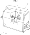
FIG. 1 is a view illustrating a machine tool in which a coolant supply device according to one embodiment of the present invention is installed. -
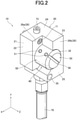
FIG. 2 is an external perspective view of the coolant supply device. -
FIG. 3 is an exploded front view of the coolant supply device. -
FIG. 4 is a right side view of a supply device body. -
FIG. 5 is a cross-sectional view taken along the line V-V inFIG. 3 . -
FIG. 6 is a cross-sectional view taken along the line VI-VI inFIG. 3 . -
FIG. 7 is a view illustrating a coolant ejection allowed state. -
FIG. 8 is a view illustrating a coolant ejection stopped state. - Hereinafter, a
coolant supply device 10 and amachine tool 1 of the present invention will be described in conjunction with the drawings. As illustrated inFIG. 1 , themachine tool 1 includes aspindle 2 and atool rest 3. Thespindle 2 can grasp (hold) a workpiece W to be machined by means of a chuck. The workpiece W is formed to have a round rod shape, supported by thespindle 2 in a manner rotatable about a Z-axis, and supplied from rearward of thespindle 2 into a workpiece machining area P. - The
coolant supply device 10 is disposed, for example, below thespindle 2 in the workpiece machining area P. Thecoolant supply device 10 is coupled to a coolant tank, and a coolant (also called a cutting oil) stored in the coolant tank is pumped up by a pump and supplied through thecoolant supply device 10 to the workpiece W. The workpiece W is machined, while the coolant is poured thereon, into a predetermined shape using a tool 4 provided to thetool rest 3. - The
coolant supply device 10 includes asupply device body 20 and arotary nozzle 40. - As illustrated in
FIG. 2 , thesupply device body 20 has a shape, for example, of substantially a rectangular solid with one corner cut off, and has arectangular fixing face 21. The fixingface 21 is fixed on a wall face which delimits the workpiece machining area P. The fixingface 21 is continuous with afront face 22 and aback face 23 in an X-axis direction, with atop face 24 and abottom face 25 in a Y-axis direction, and is opposed to anopen face 26. - For example, the
open face 26 has a stepped shape. Theopen face 26 has anopen face 26a on a front face side and anopen face 26b on a back face side, and theopen face 26a on the front face side is disposed lower than theopen face 26b on the back face side (closer to the fixing face 21). - As illustrated in
FIG. 3 , aninsertion hole 31 is formed in such a manner as to penetrate between thefixing face 21 and theopen face 26a on the front face side. Theinsertion hole 31 has an inner diameter of a size allowing therotary nozzle 40 to be inserted therein. Therotary nozzle 40 is rotatably inserted in theinsertion hole 31. - The
insertion hole 31 has an inner wall extending to theopen face 26b on the back face side and forming an opposedcurved wall 32 which can be opposed to an outer circumferential face of therotary nozzle 40. The opposedcurved wall 32 is formed between theopen face 26a on the front face side and theopen face 26b on the back face side and formed, for example, at a position from 12 o'clock direction to 7 o'clock direction, where, as illustrated inFIG. 4 , theopen face 26 as seen from theopen face 26 side is regarded as a clock dial. In such a range from 12 o'clock direction to 7 o'clock direction (ejection stopped range S: indicated by the solid line inFIG. 4 ), the opposedcurved wall 32 is opposed to anejection port 51 of therotary nozzle 40 so as to block theejection port 51. - On the other hand, when the
open face 26 is similarly regarded as a clock dial, for example, in a range from 7 o'clock direction to 12 o'clock direction (ejection allowed range V: indicated by the one-dot chain line inFIG. 4 ), the opposedcurved wall 32 is not opposed to theejection port 51 and theejection port 51 is opened. - Note that a
curved face 33 is also formed at the front of the opposedcurved wall 32, and thiscurved face 33 extends downward from an end of the opposedcurved wall 32 and does not block theejection port 51. - As illustrated in
FIG. 4 , theopen face 26a on the front face side is provided with afixing bolt hole 34 near thetop face 24. Thefixing bolt hole 34 is provided parallel to theinsertion hole 31 and penetrates theopen face 26a on the front face side and thefixing face 21. Theopen face 26b on the back face side is provided with afixing bolt hole 35 near thebottom face 25. Thefixing bolt hole 35 is provided parallel to theinsertion hole 31 and penetrates theopen face 26b on the back face side and thefixing face 21. Afixing bolt 71 is inserted into thefixing bolt hole 34 and afixing bolt 72 is inserted into thefixing bolt hole 35, and each of thefixing bolts supply device body 20 can be fixed to a wall face of the workpiece machining area P. - As illustrated in
FIG. 3 , ahose hole 37 for providing acoolant supply hose 70 is provided between thebottom face 25 and theinsertion hole 31 to penetrate the same (indicated by the broken line inFIG. 3 ). The coolant can be supplied into theinsertion hole 31 by connecting thecoolant supply hose 70 to thehose hole 37 from thebottom face 25. On the other hand, astopper bolt hole 36 is provided between thetop face 24 and theinsertion hole 31 to penetrate the same (indicated by the broken line inFIG. 3 ). Astopper bolt 73 is inserted into thestopper bolt hole 36 from thetop face 24 so that a head end of thestopper bolt 73 comes into contact with a side wall of asmall diameter portion 47 of therotary nozzle 40, thereby being capable of preventing therotary nozzle 40 from slipping off of thesupply device body 20. - The
rotary nozzle 40 includes abase portion 45 inserted into theinsertion hole 31, atrunk portion 50 having theejection port 51 for the coolant at an outer circumferential face, and ahead end portion 55 located on a side opposite to thebase portion 45 to have thetrunk portion 50 therebetween. - As illustrated in
FIG. 5 , therotary nozzle 40 has a cylindrical shape, and in the interior of therotary nozzle 40, acoolant flow passage 41 is formed along a rotation axis direction of the rotary nozzle 40 (the same as a Z-axis direction indicated inFIG. 3 ). Thecoolant flow passage 41 extends from an end of thebase portion 45 via the inside of thetrunk portion 50 before thehead end portion 55. Thecoolant flow passage 41 is closed at thebase portion 45 by astopper member 60. - The
base portion 45 has an outer circumferential face formed with anannular groove 46 and provided with a seal member (for example, an O-ring) 61. Thereby, leakage of the coolant from between the outer circumference of therotary nozzle 40 and an inner circumference of theinsertion hole 31 is prevented. - The
small diameter portion 47 is formed near theannular groove 46. Thesmall diameter portion 47 can be opposed to a head end of thecoolant supply hose 70 and functions as a coolant storage chamber before the coolant supplied from thecoolant supply hose 70 is introduced into thecoolant flow passage 41. Thesmall diameter portion 47 and thecoolant flow passage 41 communicate with each other through aninlet hole 48. Four pieces of inlet holes 48 in total are pierced in thesmall diameter portion 47, for example, at certain intervals (for example, 90°). Into thesmall diameter portion 47, the head end of thestopper bolt 73 can be also inserted. - For example, two pieces of
ejection ports 51 are provided at the outer circumferential face of thetrunk portion 50 along the rotation axis direction of the rotary nozzle 40 (the same as the Z-axis direction indicated inFIG. 3 ). As illustrated inFIG. 6 , anoutlet hole 52 is formed in thetrunk portion 50 in such a manner as to communicate theejection portion 51 and thecoolant flow passage 41 with each other. A direction in which theoutlet hole 52 is formed corresponds to an ejection direction of the coolant from theejection portion 51. - The
head end portion 55 has anadjustment groove 56 formed along the direction in which theoutlet hole 52 is formed. Therotary nozzle 40 can be easily rotated relative to thesupply device body 20 by disposing, for example, a flat head screwdriver at theadjustment groove 56 and then rotating theadjustment groove 56. From a direction in which theadjustment groove 56 is formed, the ejection direction of the coolant can be estimated. Note that a joint for rotating therotary nozzle 40 may be attached to thehead end portion 55. - Thus, the
supply device body 20 allows the ejection allowed range V and the ejection stopped range S for a coolant to be switched from each other in accordance with rotation of therotary nozzle 40. - Specifically, when the
coolant supply device 10 is disposed below thespindle 2, as described with reference toFIG. 1 , theadjustment groove 56 is rotated to orient theejection port 51 toward diagonally upward. Accordingly, as illustrated inFIG. 7(A) , a coolant C is supplied diagonally left upward, as seen inFIG. 7(A) , to the workpiece W. - Meanwhile, when the
coolant supply device 10 is disposed above thespindle 2, theadjustment groove 56 can be also rotated to orient theejection port 51 toward diagonally downward. Then, the coolant C is supplied diagonally left downward, as illustrated inFIG. 7(B) , to the workpiece W. - On the other hand, when the coolant C is not to be supplied to the workpiece W, the
adjustment groove 56 is rotated such that theejection port 51 is oriented toward the opposedcurved wall 32. Specifically, when theopen face 26 is regarded as a clock dial, placing theadjustment groove 56, for example, at a position of 1 o'clock direction, as illustrated inFIG. 8(A) , allows the opposedcurved wall 32 to block theejection port 51 so that the coolant C is not supplied. - Further, placing the
adjustment groove 56, for example, at a position of 5 o'clock direction, as illustrated inFIG. 8(B) , also allows the opposedcurved wall 32 to block theejection port 51 so that the coolant C is not supplied. - Thus, the
rotary nozzle 40 rotates so that an ejection direction of the coolant C can be changed, and accordingly thecoolant supply device 10 can be disposed at any position, for example, below thespindle 2, in the workpiece machining area P. Further, when therotary nozzle 40 rotates so that thesupply device body 20 blocks theejection port 51, ejection of the coolant C is stopped. Accordingly, ejection of the coolant C can be easily switched on and off. - The
adjustment groove 56 may be rotated during ejection of the coolant C. In such a case, during coolant ejection, the ejection direction of the coolant C can be changed. Further, during ejection of the coolant C, the ejection allowed range V and the ejection stopped range S can be also switched from each other. -
- 1
- machine tool
- 2
- spindle
- 3
- tool rest
- 4
- tool
- 10
- coolant supply device
- 20
- supply device body
- 21
- fixing face
- 22
- front face
- 23
- back face
- 24
- top face
- 25
- bottom face
- 26
- open face
- 26a
- open face on front face side
- 26b
- open face on back face side
- 31
- insertion hole
- 32
- opposed curved wall
- 33
- curved face
- 34
- fixing bolt hole
- 35
- fixing bolt hole
- 36
- stopper bolt hole
- 37
- hose hole
- 40
- rotary nozzle
- 41
- coolant flow passage
- 45
- base portion
- 46
- annular groove
- 47
- small diameter portion
- 48
- inlet hole
- 50
- trunk portion
- 51
- ejection port
- 52
- outlet hole
- 55
- head end portion
- 56
- adjustment groove
- 60
- stopper member
- 61
- seal member
- 70
- coolant supply hose
- 71
- fixing bolt
- 72
- fixing bolt
- 73
- stopper bolt
- W
- workpiece
- P
- workpiece machining area
- C
- coolant
- V
- ejection allowed range
- S
- ejection stopped range
Claims (4)
- A coolant supply device for supplying a coolant to a workpiece machining area in a machine tool, the coolant supply device comprising:a rotary nozzle formed to have a cylindrical shape and having, at an outer circumferential face thereof having the cylindrical shape, an ejection port for ejecting the coolant; anda supply device body rotatably supporting the rotary nozzle and configured to be capable of supplying the coolant to the rotary nozzle, whereinthe supply device body is configured to be capable of switching an ejection allowed range in which the ejection port is opened and an ejection stopped range in which the ejection port is blocked from each other in accordance with rotation of the rotary nozzle.
- The coolant supply device according to claim 1, wherein the supply device body includes an opposed curved wall capable of blocking the ejection port by being opposed to the ejection port.
- The coolant supply device according to claim 1 or 2, wherein the rotary nozzle includes an adjustment groove provided at an end face of the rotary nozzle and formed along the same direction as an ejection direction of the coolant from the ejection port.
- A machine tool comprising the coolant supply device according to any one of claims 1-3.
Applications Claiming Priority (2)
| Application Number | Priority Date | Filing Date | Title |
|---|---|---|---|
| JP2019116352A JP7399635B2 (en) | 2019-06-24 | 2019-06-24 | Coolant supply equipment and machine tools |
| PCT/JP2020/020798 WO2020261844A1 (en) | 2019-06-24 | 2020-05-26 | Coolant supply device and machine tool |
Publications (3)
| Publication Number | Publication Date |
|---|---|
| EP3950219A1 true EP3950219A1 (en) | 2022-02-09 |
| EP3950219A4 EP3950219A4 (en) | 2023-01-04 |
| EP3950219B1 EP3950219B1 (en) | 2026-01-28 |
Family
ID=73994592
Family Applications (1)
| Application Number | Title | Priority Date | Filing Date |
|---|---|---|---|
| EP20833574.5A Active EP3950219B1 (en) | 2019-06-24 | 2020-05-26 | Coolant supply device and machine tool |
Country Status (8)
| Country | Link |
|---|---|
| US (1) | US12311485B2 (en) |
| EP (1) | EP3950219B1 (en) |
| JP (1) | JP7399635B2 (en) |
| KR (1) | KR102890145B1 (en) |
| CN (1) | CN113874162B (en) |
| ES (1) | ES3068247T3 (en) |
| TW (1) | TWI836081B (en) |
| WO (1) | WO2020261844A1 (en) |
Families Citing this family (1)
| Publication number | Priority date | Publication date | Assignee | Title |
|---|---|---|---|---|
| JP2024071966A (en) * | 2022-11-15 | 2024-05-27 | 株式会社不二越 | Multi-tasking machine cleaning tools |
Family Cites Families (29)
| Publication number | Priority date | Publication date | Assignee | Title |
|---|---|---|---|---|
| US3094283A (en) * | 1962-07-25 | 1963-06-18 | Alex V Balister | Lubricating device |
| IT1179552B (en) | 1984-01-13 | 1987-09-16 | Alessandro Quercetti E C | PROCEDURE FOR THE MANUFACTURE OF BOXES IN CONFANET BOXES THAT RESULT AND ELEMENTS FOR THEIR TRAINING |
| JPS60172646U (en) | 1984-04-23 | 1985-11-15 | 富士テクノ工業株式会社 | swivel nozzle |
| JPH02311240A (en) * | 1989-05-27 | 1990-12-26 | Okuma Mach Works Ltd | Rotary air blowing device |
| DE4129402A1 (en) * | 1991-09-04 | 1993-03-11 | Blohm Maschinenbau Gmbh | COOLING DEVICE FOR A GRINDING MACHINE |
| JPH0724542A (en) | 1993-07-12 | 1995-01-27 | Komatsu Ltd | Work support device for plate processing machine |
| JPH0724542U (en) | 1993-10-13 | 1995-05-09 | 日立精機株式会社 | Machine tool injection nozzle |
| JPH08243876A (en) * | 1995-03-10 | 1996-09-24 | Toyoda Mach Works Ltd | Chip removal device |
| JP4310048B2 (en) | 1998-12-28 | 2009-08-05 | 株式会社ゼータ平和 | Coolant liquid nozzle for machine tools |
| JP2004041999A (en) | 2002-07-16 | 2004-02-12 | Mechatro Shinshu:Kk | Washing nozzle mounting device |
| US8074543B2 (en) * | 2007-03-01 | 2011-12-13 | Mori Seiki Usa, Inc. | Machine tool with cooling nozzle and method for applying cooling fluid |
| CN101275533A (en) * | 2008-04-28 | 2008-10-01 | 熊鹰 | Afflux adjustable multiple-jet diagonal flow water turbine |
| CN201257413Y (en) * | 2008-08-19 | 2009-06-17 | 台山市戴隆塑料制品有限公司 | Spinner nozzle |
| CN101797697A (en) * | 2009-02-05 | 2010-08-11 | 嵩富机具厂有限公司 | Machine tool rotary nozzle device and control method thereof |
| JP5496787B2 (en) | 2010-06-15 | 2014-05-21 | 株式会社ディスコ | Cutting device |
| JP5756331B2 (en) * | 2011-04-25 | 2015-07-29 | ミネベア株式会社 | Coolant injection device |
| JP5816056B2 (en) * | 2011-11-04 | 2015-11-17 | ミネベア株式会社 | Structure for supplying grinding fluid to bi-directionally operating coolant nozzle and coolant nozzle having this structure |
| JP5756743B2 (en) * | 2011-12-27 | 2015-07-29 | ミネベア株式会社 | Cutting fluid injection device |
| JP6062838B2 (en) * | 2013-09-30 | 2017-01-18 | ミネベア株式会社 | Coolant injection device |
| JP2015085403A (en) * | 2013-10-28 | 2015-05-07 | ミネベア株式会社 | Coolant injection device |
| CN203824461U (en) * | 2014-04-29 | 2014-09-10 | 四川工程职业技术学院 | Tool for detecting precision and effective length of internal thread of blind screw hole |
| JP6580832B2 (en) | 2015-01-22 | 2019-09-25 | エンシュウ株式会社 | Machine tool and original posture return processing program |
| CN205166533U (en) * | 2015-10-13 | 2016-04-20 | 钱文兵 | Cooling device with adjustable machine tool machining uses |
| JP6630937B2 (en) * | 2015-12-07 | 2020-01-15 | 株式会社いけうち | Rotary spray nozzle |
| CN205394146U (en) * | 2016-02-29 | 2016-07-27 | 济南大学 | A variable angle vortex shower nozzle device for cutting coolant |
| CN205504112U (en) * | 2016-04-16 | 2016-08-24 | 河北润旺达洁具制造有限公司 | Press down time delay case structure with adjustable flow |
| CN206205098U (en) | 2016-09-30 | 2017-05-31 | 佛山市顺德区乐华陶瓷洁具有限公司 | A kind of adjustable water-outlet type shower nozzle for urinal |
| JP6738767B2 (en) | 2017-04-27 | 2020-08-12 | モバック株式会社 | Spindle device |
| CN108555685B (en) * | 2018-07-02 | 2020-04-07 | 青岛理工大学 | CNC milling machine multi-degree-of-freedom micro-lubrication intelligent nozzle system |
-
2019
- 2019-06-24 JP JP2019116352A patent/JP7399635B2/en active Active
-
2020
- 2020-05-25 TW TW109117354A patent/TWI836081B/en active
- 2020-05-26 ES ES20833574T patent/ES3068247T3/en active Active
- 2020-05-26 EP EP20833574.5A patent/EP3950219B1/en active Active
- 2020-05-26 WO PCT/JP2020/020798 patent/WO2020261844A1/en not_active Ceased
- 2020-05-26 KR KR1020217036074A patent/KR102890145B1/en active Active
- 2020-05-26 CN CN202080037696.9A patent/CN113874162B/en active Active
- 2020-05-26 US US17/604,855 patent/US12311485B2/en active Active
Also Published As
| Publication number | Publication date |
|---|---|
| CN113874162B (en) | 2024-03-05 |
| TW202100289A (en) | 2021-01-01 |
| EP3950219A4 (en) | 2023-01-04 |
| CN113874162A (en) | 2021-12-31 |
| WO2020261844A1 (en) | 2020-12-30 |
| US20220219273A1 (en) | 2022-07-14 |
| JP2021000706A (en) | 2021-01-07 |
| US12311485B2 (en) | 2025-05-27 |
| KR102890145B1 (en) | 2025-11-25 |
| KR20220021461A (en) | 2022-02-22 |
| EP3950219B1 (en) | 2026-01-28 |
| ES3068247T3 (en) | 2026-05-28 |
| JP7399635B2 (en) | 2023-12-18 |
| TWI836081B (en) | 2024-03-21 |
Similar Documents
| Publication | Publication Date | Title |
|---|---|---|
| EP3248721B1 (en) | Tool comprising a tool holder | |
| US20080206004A1 (en) | Multiple machine tool support block and tool post having internal coolant supply | |
| WO2015056406A1 (en) | Cutting tool holder and cutting tool | |
| US10040129B2 (en) | Tool head having a shrink-fit chuck | |
| EP2987575B1 (en) | A clamping device | |
| CN105290873B (en) | Device for feeding a cooling or lubricating medium to a rotating tool | |
| JP6769530B1 (en) | Cutting tools | |
| US3375742A (en) | Turret mechanism | |
| EP3950219B1 (en) | Coolant supply device and machine tool | |
| US4573836A (en) | Device for transferring fluid to a rotating tool holder | |
| US20130069322A1 (en) | Tool Holder | |
| JPWO2014167669A1 (en) | Hydro chuck | |
| US4648759A (en) | Automatic coolant inducer arrangement | |
| US10226845B2 (en) | Machine tool | |
| JP2020062700A (en) | Cooling liquid supply device | |
| JPH0899245A (en) | Tool holder cap for liquid supply | |
| JP2003181743A (en) | Tool holder for lathe | |
| JP4925777B2 (en) | Turret with coolant supply device | |
| JP6871822B2 (en) | Tool holder and tap oil supply unit | |
| JPH0663207U (en) | Chuck | |
| JP4820166B2 (en) | Machine tool spindle equipment | |
| JP3695646B2 (en) | Tool holder | |
| KR100600024B1 (en) | Coolant adapter for changing coolant flow paths applied to turrets | |
| JP6305164B2 (en) | Tool holder and machine tool | |
| JPH0636749U (en) | Fluid supply device for turret |
Legal Events
| Date | Code | Title | Description |
|---|---|---|---|
| STAA | Information on the status of an ep patent application or granted ep patent |
Free format text: STATUS: THE INTERNATIONAL PUBLICATION HAS BEEN MADE |
|
| PUAI | Public reference made under article 153(3) epc to a published international application that has entered the european phase |
Free format text: ORIGINAL CODE: 0009012 |
|
| STAA | Information on the status of an ep patent application or granted ep patent |
Free format text: STATUS: REQUEST FOR EXAMINATION WAS MADE |
|
| 17P | Request for examination filed |
Effective date: 20211025 |
|
| AK | Designated contracting states |
Kind code of ref document: A1 Designated state(s): AL AT BE BG CH CY CZ DE DK EE ES FI FR GB GR HR HU IE IS IT LI LT LU LV MC MK MT NL NO PL PT RO RS SE SI SK SM TR |
|
| RIN1 | Information on inventor provided before grant (corrected) |
Inventor name: KAI, SHINPEI Inventor name: ANDO, YOSUKE Inventor name: SHIDA, TADAYASU Inventor name: YABE, KOICHI |
|
| DAV | Request for validation of the european patent (deleted) | ||
| DAX | Request for extension of the european patent (deleted) | ||
| A4 | Supplementary search report drawn up and despatched |
Effective date: 20221205 |
|
| RIC1 | Information provided on ipc code assigned before grant |
Ipc: B05B 1/04 20060101ALI20221129BHEP Ipc: B05B 1/14 20060101ALI20221129BHEP Ipc: B05B 1/30 20060101ALI20221129BHEP Ipc: B23Q 11/10 20060101AFI20221129BHEP |
|
| GRAP | Despatch of communication of intention to grant a patent |
Free format text: ORIGINAL CODE: EPIDOSNIGR1 |
|
| STAA | Information on the status of an ep patent application or granted ep patent |
Free format text: STATUS: GRANT OF PATENT IS INTENDED |
|
| RIC1 | Information provided on ipc code assigned before grant |
Ipc: B23Q 11/10 20060101AFI20250819BHEP Ipc: B05B 1/30 20060101ALI20250819BHEP Ipc: B05B 1/14 20060101ALI20250819BHEP Ipc: B05B 1/04 20060101ALI20250819BHEP |
|
| INTG | Intention to grant announced |
Effective date: 20250919 |
|
| GRAS | Grant fee paid |
Free format text: ORIGINAL CODE: EPIDOSNIGR3 |
|
| GRAA | (expected) grant |
Free format text: ORIGINAL CODE: 0009210 |
|
| STAA | Information on the status of an ep patent application or granted ep patent |
Free format text: STATUS: THE PATENT HAS BEEN GRANTED |
|
| AK | Designated contracting states |
Kind code of ref document: B1 Designated state(s): AL AT BE BG CH CY CZ DE DK EE ES FI FR GB GR HR HU IE IS IT LI LT LU LV MC MK MT NL NO PL PT RO RS SE SI SK SM TR |
|
| REG | Reference to a national code |
Ref country code: CH Ref legal event code: F10 Free format text: ST27 STATUS EVENT CODE: U-0-0-F10-F00 (AS PROVIDED BY THE NATIONAL OFFICE) Effective date: 20260128 Ref country code: GB Ref legal event code: FG4D |
|
| REG | Reference to a national code |
Ref country code: DE Ref legal event code: R096 Ref document number: 602020066155 Country of ref document: DE |
|
| REG | Reference to a national code |
Ref country code: IE Ref legal event code: FG4D |
|
| REG | Reference to a national code |
Ref country code: ES Ref legal event code: FG2A Ref document number: 3068247 Country of ref document: ES Kind code of ref document: T3 Effective date: 20260528 |
|
| REG | Reference to a national code |
Ref country code: CH Ref legal event code: U11 Free format text: ST27 STATUS EVENT CODE: U-0-0-U10-U11 (AS PROVIDED BY THE NATIONAL OFFICE) Effective date: 20260601 |
|
| REG | Reference to a national code |
Ref country code: NL Ref legal event code: MP Effective date: 20260128 |
|
| PG25 | Lapsed in a contracting state [announced via postgrant information from national office to epo] |
Ref country code: NL Free format text: LAPSE BECAUSE OF FAILURE TO SUBMIT A TRANSLATION OF THE DESCRIPTION OR TO PAY THE FEE WITHIN THE PRESCRIBED TIME-LIMIT Effective date: 20260128 |
|
| REG | Reference to a national code |
Ref country code: AT Ref legal event code: MK05 Ref document number: 1880578 Country of ref document: AT Kind code of ref document: T Effective date: 20260128 |
|
| PG25 | Lapsed in a contracting state [announced via postgrant information from national office to epo] |
Ref country code: RS Free format text: LAPSE BECAUSE OF FAILURE TO SUBMIT A TRANSLATION OF THE DESCRIPTION OR TO PAY THE FEE WITHIN THE PRESCRIBED TIME-LIMIT Effective date: 20260428 |
|
| PGFP | Annual fee paid to national office [announced via postgrant information from national office to epo] |
Ref country code: ES Payment date: 20260618 Year of fee payment: 7 |
|
| PG25 | Lapsed in a contracting state [announced via postgrant information from national office to epo] |
Ref country code: PL Free format text: LAPSE BECAUSE OF FAILURE TO SUBMIT A TRANSLATION OF THE DESCRIPTION OR TO PAY THE FEE WITHIN THE PRESCRIBED TIME-LIMIT Effective date: 20260128 |
|
| PGFP | Annual fee paid to national office [announced via postgrant information from national office to epo] |
Ref country code: GB Payment date: 20260521 Year of fee payment: 7 |
|
| PG25 | Lapsed in a contracting state [announced via postgrant information from national office to epo] |
Ref country code: GR Free format text: LAPSE BECAUSE OF FAILURE TO SUBMIT A TRANSLATION OF THE DESCRIPTION OR TO PAY THE FEE WITHIN THE PRESCRIBED TIME-LIMIT Effective date: 20260429 |
|
| PGFP | Annual fee paid to national office [announced via postgrant information from national office to epo] |
Ref country code: IT Payment date: 20260529 Year of fee payment: 7 |
|
| REG | Reference to a national code |
Ref country code: LT Ref legal event code: MG9D |
|
| PG25 | Lapsed in a contracting state [announced via postgrant information from national office to epo] |
Ref country code: LT Free format text: LAPSE BECAUSE OF FAILURE TO SUBMIT A TRANSLATION OF THE DESCRIPTION OR TO PAY THE FEE WITHIN THE PRESCRIBED TIME-LIMIT Effective date: 20260128 |
|
| PG25 | Lapsed in a contracting state [announced via postgrant information from national office to epo] |
Ref country code: NO Free format text: LAPSE BECAUSE OF FAILURE TO SUBMIT A TRANSLATION OF THE DESCRIPTION OR TO PAY THE FEE WITHIN THE PRESCRIBED TIME-LIMIT Effective date: 20260428 |
|
| PG25 | Lapsed in a contracting state [announced via postgrant information from national office to epo] |
Ref country code: SE Free format text: LAPSE BECAUSE OF FAILURE TO SUBMIT A TRANSLATION OF THE DESCRIPTION OR TO PAY THE FEE WITHIN THE PRESCRIBED TIME-LIMIT Effective date: 20260128 Ref country code: FI Free format text: LAPSE BECAUSE OF FAILURE TO SUBMIT A TRANSLATION OF THE DESCRIPTION OR TO PAY THE FEE WITHIN THE PRESCRIBED TIME-LIMIT Effective date: 20260128 Ref country code: AT Free format text: LAPSE BECAUSE OF FAILURE TO SUBMIT A TRANSLATION OF THE DESCRIPTION OR TO PAY THE FEE WITHIN THE PRESCRIBED TIME-LIMIT Effective date: 20260128 |
|
| PGFP | Annual fee paid to national office [announced via postgrant information from national office to epo] |
Ref country code: CH Payment date: 20260601 Year of fee payment: 7 |
|
| PG25 | Lapsed in a contracting state [announced via postgrant information from national office to epo] |
Ref country code: HR Free format text: LAPSE BECAUSE OF FAILURE TO SUBMIT A TRANSLATION OF THE DESCRIPTION OR TO PAY THE FEE WITHIN THE PRESCRIBED TIME-LIMIT Effective date: 20260128 |
|
| PG25 | Lapsed in a contracting state [announced via postgrant information from national office to epo] |
Ref country code: IS Free format text: LAPSE BECAUSE OF FAILURE TO SUBMIT A TRANSLATION OF THE DESCRIPTION OR TO PAY THE FEE WITHIN THE PRESCRIBED TIME-LIMIT Effective date: 20260528 Ref country code: PT Free format text: LAPSE BECAUSE OF FAILURE TO SUBMIT A TRANSLATION OF THE DESCRIPTION OR TO PAY THE FEE WITHIN THE PRESCRIBED TIME-LIMIT Effective date: 20260528 |
|
| PG25 | Lapsed in a contracting state [announced via postgrant information from national office to epo] |
Ref country code: LV Free format text: LAPSE BECAUSE OF FAILURE TO SUBMIT A TRANSLATION OF THE DESCRIPTION OR TO PAY THE FEE WITHIN THE PRESCRIBED TIME-LIMIT Effective date: 20260128 |
|
| PG25 | Lapsed in a contracting state [announced via postgrant information from national office to epo] |
Ref country code: BG Free format text: LAPSE BECAUSE OF FAILURE TO SUBMIT A TRANSLATION OF THE DESCRIPTION OR TO PAY THE FEE WITHIN THE PRESCRIBED TIME-LIMIT Effective date: 20260128 |