EP3947154B1 - Lufteinlasshülse für eine gondel einer antriebseinheit eines flugzeugs - Google Patents
Lufteinlasshülse für eine gondel einer antriebseinheit eines flugzeugs Download PDFInfo
- Publication number
- EP3947154B1 EP3947154B1 EP20728114.8A EP20728114A EP3947154B1 EP 3947154 B1 EP3947154 B1 EP 3947154B1 EP 20728114 A EP20728114 A EP 20728114A EP 3947154 B1 EP3947154 B1 EP 3947154B1
- Authority
- EP
- European Patent Office
- Prior art keywords
- lip
- air inlet
- duct
- annular
- nacelle
- Prior art date
- Legal status (The legal status is an assumption and is not a legal conclusion. Google has not performed a legal analysis and makes no representation as to the accuracy of the status listed.)
- Active
Links
Images

Classifications
-
- F—MECHANICAL ENGINEERING; LIGHTING; HEATING; WEAPONS; BLASTING
- F02—COMBUSTION ENGINES; HOT-GAS OR COMBUSTION-PRODUCT ENGINE PLANTS
- F02C—GAS-TURBINE PLANTS; AIR INTAKES FOR JET-PROPULSION PLANTS; CONTROLLING FUEL SUPPLY IN AIR-BREATHING JET-PROPULSION PLANTS
- F02C7/00—Features, components parts, details or accessories, not provided for in, or of interest apart form groups F02C1/00 - F02C6/00; Air intakes for jet-propulsion plants
- F02C7/04—Air intakes for gas-turbine plants or jet-propulsion plants
- F02C7/057—Control or regulation
-
- B—PERFORMING OPERATIONS; TRANSPORTING
- B64—AIRCRAFT; AVIATION; COSMONAUTICS
- B64D—EQUIPMENT FOR FITTING IN OR TO AIRCRAFT; FLIGHT SUITS; PARACHUTES; ARRANGEMENT OR MOUNTING OF POWER PLANTS OR PROPULSION TRANSMISSIONS IN AIRCRAFT
- B64D29/00—Power-plant nacelles, fairings or cowlings
-
- B—PERFORMING OPERATIONS; TRANSPORTING
- B64—AIRCRAFT; AVIATION; COSMONAUTICS
- B64D—EQUIPMENT FOR FITTING IN OR TO AIRCRAFT; FLIGHT SUITS; PARACHUTES; ARRANGEMENT OR MOUNTING OF POWER PLANTS OR PROPULSION TRANSMISSIONS IN AIRCRAFT
- B64D33/00—Arrangement in aircraft of power plant parts or auxiliaries not otherwise provided for
- B64D33/02—Arrangement in aircraft of power plant parts or auxiliaries not otherwise provided for of combustion air intakes
-
- F—MECHANICAL ENGINEERING; LIGHTING; HEATING; WEAPONS; BLASTING
- F02—COMBUSTION ENGINES; HOT-GAS OR COMBUSTION-PRODUCT ENGINE PLANTS
- F02C—GAS-TURBINE PLANTS; AIR INTAKES FOR JET-PROPULSION PLANTS; CONTROLLING FUEL SUPPLY IN AIR-BREATHING JET-PROPULSION PLANTS
- F02C7/00—Features, components parts, details or accessories, not provided for in, or of interest apart form groups F02C1/00 - F02C6/00; Air intakes for jet-propulsion plants
- F02C7/04—Air intakes for gas-turbine plants or jet-propulsion plants
- F02C7/042—Air intakes for gas-turbine plants or jet-propulsion plants having variable geometry
-
- F—MECHANICAL ENGINEERING; LIGHTING; HEATING; WEAPONS; BLASTING
- F05—INDEXING SCHEMES RELATING TO ENGINES OR PUMPS IN VARIOUS SUBCLASSES OF CLASSES F01-F04
- F05D—INDEXING SCHEME FOR ASPECTS RELATING TO NON-POSITIVE-DISPLACEMENT MACHINES OR ENGINES, GAS-TURBINES OR JET-PROPULSION PLANTS
- F05D2260/00—Function
- F05D2260/50—Kinematic linkage, i.e. transmission of position
Definitions
- the invention relates to the field of aeronautics, and more particularly, to an air inlet sleeve for a nacelle of an aircraft propulsion assembly.
- the state of the art includes in particular the documents US-A-3400902 , US-A-4047911 And US-2014/127001 .
- a propulsion assembly comprises a turbomachine type engine which is surrounded by a nacelle.
- the air flow which passes through the air inlet sleeve passes through a fan blade then divides into a primary air flow which enters the turbomachine and into a secondary air flow which flows around the turbomachine.
- the nacelle comprises an air inlet sleeve, a middle structure and a downstream structure all connected together so as to form a flow path for the secondary air flow.
- the air inlet sleeve comprises, on the one hand, an air inlet lip arranged to allow optimal capture of the air necessary for powering the engine, over its entire range operating, while minimizing losses and drag, and on the other hand a body on which the lip is attached and which is intended to properly channel the air towards the fan blade.
- Requests FR2936492A1 And FR2938237A1 describe such air inlet sleeves whose lips are attached to the bodies when the aircraft is moving but are configured to move away from the body when the aircraft is on the ground in order to facilitate maintenance of the nacelle.
- the current trend is to reduce the length of the nacelles and consequently of the air inlet sleeves, which reduces their air capture capacity, particularly in the unfavorable conditions described above.
- the present invention makes it possible to remedy the aforementioned problem in a simple, effective and economical manner.
- the invention proposes an air inlet sleeve for a nacelle of a propulsion assembly according to claim 1.
- the invention allows a transverse air flow to enter the nacelle through this spacing before be straightened by crossing the grids in an optimized direction.
- the direction of the transverse air flow after having been straightened by the grilles can in particular be chosen to reduce the risk of air separation in the air inlet sleeve and therefore to reduce the risk of distortion of the air flow powering the turbomachine and its fan.
- This straightening also makes it possible to better distribute the transverse air flow entering the engine and therefore to increase its air capture surface.
- the invention thus makes it possible to prevent parts of the engine, in particular peripheral parts (that is to say located close to the nacelle), from being passed through by the air flow at all or only minimally.
- the air inlet sleeve according to the invention thus makes it possible to increase the flow rate of the air flow captured by the air inlet sleeve, to better direct it and to improve its distribution inside the the nacelle, particularly in the unfavorable conditions described above.
- the engine thus gains in performance and operability.
- the invention has the advantage of allowing the grids to be housed in the body without modifying the external structure of the lip.
- the invention also relates to an aircraft propulsion assembly comprising a nacelle equipped with a sleeve as described above.
- a propulsion assembly 10 comprises an engine or a turbomachine which is surrounded by a nacelle 26.
- the turbomachine is a dual-flow turbojet which comprises, from upstream to downstream in the direction of gas flow, a low pressure compressor (LP) 12, a high pressure compressor (HP) 14, an annular chamber combustion 16, a high pressure turbine (HP) 18 and a low pressure turbine (LP) 20, which define a flow path for a primary flow of gas 22.
- LP low pressure compressor
- HP high pressure compressor
- HP annular chamber combustion
- HP high pressure turbine
- LP low pressure turbine
- the rotor of the high pressure turbine 18 is integral with the rotor of the high pressure compressor 14 so as to form a high body pressure
- the rotor of the low pressure turbine 20 is integral with the rotor of the low pressure compressor 12 so as to form a low pressure body.
- the rotor of each turbine rotates the rotor of the associated compressor around a longitudinal axis 24 under the effect of the thrust of the gases coming from the combustion chamber 16.
- upstream and downstream refer to the flow of gases in the turbomachine, along the longitudinal axis 24, and the terms upstream, downstream, radial, transverse, etc., must be considered as being defined in relation to this longitudinal axis 24 or referring to this longitudinal axis 24.
- the nacelle 26 comprises, from upstream to downstream, an air inlet sleeve 60, a middle structure 34 and a downstream structure 36 connected together so as to extend around the turbomachine and define around the latter an annular vein for the flow of a secondary flow 28.
- the air inlet sleeve 60 comprises an annular air inlet lip 40 adapted to allow optimal capture of the air necessary for supplying a fan 32 of the turbomachine. This air then divides to form the aforementioned primary 22 and secondary 28 flows.
- the lip 40 defines a transverse inlet 38 of the nacelle 26 allowing air to enter the nacelle.
- This lip 40 comprises two annular walls 41, 42 coaxial with respect to the longitudinal axis 24, respectively internal 41 and external 42.
- the internal wall 41 defines part of an internal annular surface of the air inlet sleeve 60 making it possible to capture the air flows and guide them towards the blower 32.
- the internal wall 41 thus forms part of the vein annular part of the nacelle.
- the external wall 42 defines a part of an external annular surface of the air inlet sleeve 60.
- the air inlet sleeve 60 also comprises an annular body 50 comprising an internal body wall 51 and an external body wall 52.
- the internal body wall 51 defines another part of the internal annular surface of the sleeve. air inlet 60 and therefore makes it possible to guide the flow of air entering the nacelle 26 from the lip 40 towards the fan 32.
- the internal wall of the body 51 is part of the annular flow path of the nacelle 26.
- the external wall of the body 52 defines another part of the external annular surface of the air inlet sleeve 60.
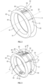
- FIG 2 represents the air inlet sleeve 60 according to the invention comprising the annular body 50 and the annular air inlet lip 40 as described above.
- the external body wall of the body 50 is not shown to facilitate the presentation of the invention.
- the air inlet sleeve 60 here comprises a control system 70 for the movement in axial translation of the lip 40 with respect to the body 50, that is to say parallel to the longitudinal axis 24.
- the control system 70 is thus arranged to move the lip 40 from a first position ( figure 2 ), in which the lip 40 is attached to the body 50, at a second position ( Figure 3 ) in which it is distanced axially from the body 50.
- control system 70 comprises for example at least one cylinder 71, here four cylinders 71, in particular electric or hydraulic. They are in particular oriented substantially parallel to the longitudinal axis 24 of the air inlet sleeve 60 so as to push the lip 40 to bring it from the first position shown in the figure 2 to the second position shown in Figure 3 and so as to be able to pull the lip 40 in the opposite direction.
- Round 60 of the figure 2 further comprises at least one guiding system 80 in translation of the lip 40 with respect to the body 50.
- the guiding system 80 is here of the rail and slide type and comprises for example a lower system 81 and an upper system 82 as visible in the Figure 3 .
- the lower 81 and upper 82 systems each comprise a rail 83 and a slide 84.
- the rail 83 is here located on the body 50, in particular on the internal wall of the body 51 and the slide on the lip 40.
- the rail 83 and the slide 84 are configured to guide the lip 40 parallel to the longitudinal axis 24 during its movements of the first position to the second position and vice versa.
- the slide 84 comprises two edges 85 spaced apart so as to define a space 86.
- the rail 83 comprises two U-shaped profiles 87 arranged to be housed in the space 86 in the first position and free the space 86 in the second position.
- the edges 85 and the profiles 87 are configured to allow the axial movement of the lip 40 relative to the body 50 and prevent any other type of movement.
- the lip 40 When the lip 40 is in the first position, it is removably fixed to the body 50 by at least one flange, for example located on the internal wall 41 of the lip 40 and the internal wall of the body 51 of the body 50 and/or on the external wall 42 of the lip 40 and the external wall of the body of the body 52.
- the centering of the lip 40 relative to the body is done in particular by means of a centering finger located on an element among the lip 40 and the body 50 and a location of complementary shape to the finger and arranged on the other of the elements among the lip 40 and the body 50.
- the longitudinal translation of the lip 40 relative to the body 50 thus makes it possible to increase the air flow captured by the air inlet sleeve 60 without modifying the section of the transverse entry.
- the air flows 102 entering the nacelle via the transverse inlet of the nacelle are therefore not disturbed by the invention.
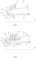
- the lip 40 further comprises an annular row of grids 90.
- This annular row of grids 90 is integral in translation with the lip 40.
- the grids are in particular configured to be, in the first position ( figure 4 ), housed in the body 50, and, in the second position ( figure 5 ), outlets from the body 50 and intended to be crossed by the transverse air flow 100.
- the grilles 90 include fins 91 which guide the transverse air flow 100 when it enters the nacelle via the side inlet 46 in a direction illustrated by the arrows referenced 101 on the figure 5 .
- the invention thus makes it possible to configure the fins 91 so as to optimize the direction of the transverse air flow 100 in order to optimize the performance of the engine.
- the grilles 90 prevent the entry of birds into the nacelle via the side entrance 46 and thus have an anti-bird collusion protection function.
- the slide(s) 84 are in particular provided in the grids 90.
- the air flow can enter the nacelle by crossing the grids 90 and/or by crossing the slide 84, in particular by space 86.
- the invention is advantageous for all types of nacelles and in particular for nacelles with large cross sections.
- the effect of the side inlet 46 on the air flow entering the nacelle is thus accentuated on nacelles having a large cross section.
- the lip 40 comprises for example a transverse annular reinforcement wall 43.
- This reinforcement wall 43 defines with the internal 41 and external walls 42 an annular receiving compartment 44 traversed by a pipe 45 for circulating a fluid for defrosting the lip 40.
- the invention thus makes it possible to be compatible with a defrosting system effective, preventing the lip 40 which is directly subject to external climatic conditions from icing.
- the air inlet sleeve 60 will remain in the normally closed position, that is to say in first position.
Landscapes
- Engineering & Computer Science (AREA)
- Chemical & Material Sciences (AREA)
- Combustion & Propulsion (AREA)
- Mechanical Engineering (AREA)
- General Engineering & Computer Science (AREA)
- Aviation & Aerospace Engineering (AREA)
- Physics & Mathematics (AREA)
- Geometry (AREA)
- Structures Of Non-Positive Displacement Pumps (AREA)
- Wind Motors (AREA)
- Professional, Industrial, Or Sporting Protective Garments (AREA)
Claims (6)
- Lufteinlasshülse (60) für eine Gondel (26) einer Flugzeug-Antriebseinheit (10), wobei diese Hülse (60) einen ringförmigen Körper (50) und eine ringförmige Lufteinlasslippe (40) umfasst, die zwei koaxiale ringförmige Wände (41, 42), eine innere (41) bzw. eine äußere (42), umfasst, wobei die innere Wand (41) einen Teil einer inneren ringförmigen Fläche der Lufteinlasshülse (60) definiert und die äußere Wand (42) einen Teil einer äußeren ringförmigen Fläche der Lufteinlasshülse (60) definiert, wobei die Lufteinlasshülse (60) weiter ein Steuersystem (70) für die axiale Verschiebebewegung der Lippe (40) gegenüber dem Körper (50) von einer ersten Position, in der die Lippe (40) an den Körper (50) angefügt ist, bis zu einer zweiten Position, in der die Lippe (40) axial vom Körper (50) beabstandet ist, umfasst, wobei die Hülse (60) weiter eine ringförmige Reihe von Gittern (90) umfasst, die in der Translation mit der Lippe (40) integriert sind und die so konfiguriert sind, dass sie in der ersten Position im Körper (50) untergebracht und in der zweiten Position aus dem Körper (50) herausbewegt sind, und dazu bestimmt sind, von einem Luftstrom (100), der in die Lufteinlasshülse (60) eintritt, durchquert zu werden,wobei die Hülse (60) mindestens ein System (80) zur Translationsführung der Lippe (40) gegenüber dem Körper (50) umfasst, dadurch gekennzeichnet, dass das Führungssystem (80) vom Typ mit Schiene (83) und Gleitstück (84) ist,wobei sich die Schiene (83) am Körper (50) befindet und das Gleitstück (84) sich an der Lippe (40) befindet, wobei die Schiene (83) und das Gleitstück (84) so konfiguriert sind, dass sie die Lippe (40) bei ihren Bewegungen von der ersten Position in die zweite Position und umgekehrt parallel zu einer Längsachse (24) der Lufteinlasshülse (60) führen,wobei das Gleitstück (84) in den Gittern (90) so ausgestaltet ist, dass der Luftstrom (100) in die Gondel eintritt, indem er die Gitter (90) und/oder das Gleitstück (84) durchquert, wenn sich die Lippe (40) in der zweiten Position befindet,und dadurch, dass das Gleitstück (84) zwei Kanten (85) umfasst, die so voneinander beabstandet sind, dass sie einen Raum (86) definieren, die Schiene (83) zwei U-förmige Profile umfasst, die so angeordnet sind, dass sie in der ersten Position in dem Raum (86) untergebracht sind und in der zweiten Position den Raum (86) freigeben, wobei die Kanten (85) und die Profile (87) so konfiguriert sind, dass sie die axiale Bewegung der Lippe (40) in Bezug auf den Körper (50) ermöglichen und jede andere Art von Bewegung verhindern.
- Hülse (60) nach dem vorstehenden Anspruch, wobei das Steuersystem (70) mindestens einen Zylinder (71) umfasst, der im Wesentlichen parallel zu einer Längsachse (24) der Lufteinlasshülse (60) ausgerichtet ist.
- Hülse (60) nach einem der vorstehenden Ansprüche, wobei die Wände (41, 42) durch eine ringförmige, quer verlaufende Verstärkungswand (43) miteinander verbunden sind.
- Hülse (60) nach Anspruch 3, wobei die Verstärkungswand (43) zusammen mit der Innen- (41) und der Außenwand (42) ein ringförmiges Aufnahmefach (44) definiert, das von einer Kanalisation (45) für die Zirkulation eines Enteisungsfluids für die Lippe (40) durchzogen ist.
- Hülse nach Anspruch 1, wobei die Lippe (40) durch mindestens einen Flansch abnehmbar am Körper (50) befestigt ist, wenn sich die Lippe (40) in der ersten Position befindet.
- Flugzeug-Antriebseinheit (10), die eine Gondel (26) umfasst, welche mit einer Hülse (60) nach einem der vorstehenden Ansprüche ausgestattet ist.
Applications Claiming Priority (2)
| Application Number | Priority Date | Filing Date | Title |
|---|---|---|---|
| FR1903499A FR3094698B1 (fr) | 2019-04-02 | 2019-04-02 | Manche d’entree d’air pour une nacelle d’un ensemble propulsif d’aeronef |
| PCT/FR2020/050594 WO2020201658A1 (fr) | 2019-04-02 | 2020-03-19 | Manche d'entree d'air pour une nacelle d'un ensemble propulsif d'aeronef |
Publications (2)
| Publication Number | Publication Date |
|---|---|
| EP3947154A1 EP3947154A1 (de) | 2022-02-09 |
| EP3947154B1 true EP3947154B1 (de) | 2024-07-24 |
Family
ID=67262703
Family Applications (1)
| Application Number | Title | Priority Date | Filing Date |
|---|---|---|---|
| EP20728114.8A Active EP3947154B1 (de) | 2019-04-02 | 2020-03-19 | Lufteinlasshülse für eine gondel einer antriebseinheit eines flugzeugs |
Country Status (5)
| Country | Link |
|---|---|
| US (1) | US12129795B2 (de) |
| EP (1) | EP3947154B1 (de) |
| CN (1) | CN113646233B (de) |
| FR (1) | FR3094698B1 (de) |
| WO (1) | WO2020201658A1 (de) |
Families Citing this family (3)
| Publication number | Priority date | Publication date | Assignee | Title |
|---|---|---|---|---|
| FR3094698B1 (fr) * | 2019-04-02 | 2022-09-09 | Safran Aircraft Engines | Manche d’entree d’air pour une nacelle d’un ensemble propulsif d’aeronef |
| CN115289499B (zh) * | 2022-10-08 | 2023-01-10 | 成都中科翼能科技有限公司 | 一种燃气轮机燃烧室进气口的空心支板 |
| CN116513466B (zh) * | 2023-04-21 | 2025-08-19 | 中航西安飞机工业集团股份有限公司 | 一种涡桨飞机发动机整流唇口及其柔性整体成形方法 |
Citations (1)
| Publication number | Priority date | Publication date | Assignee | Title |
|---|---|---|---|---|
| US20100084507A1 (en) * | 2006-10-02 | 2010-04-08 | Aircelle | Removable air intake structure for turbojet engine nacelle |
Family Cites Families (33)
| Publication number | Priority date | Publication date | Assignee | Title |
|---|---|---|---|---|
| US3400902A (en) * | 1966-01-13 | 1968-09-10 | Ben J. King | Gas inlet conversion and protection means |
| US4047911A (en) * | 1973-04-12 | 1977-09-13 | Dornier Gmbh | Air intake with deflecting device against foreign objects impinging in the initial direction of air flow at engine nacelles |
| US5014933A (en) * | 1989-04-27 | 1991-05-14 | The Boeing Company | Translating lip aircraft cowling structure adapted for noise reduction |
| GB9301457D0 (en) * | 1993-01-26 | 1993-03-17 | Short Brothers Plc | An aircraft propulsuve power unit |
| US5778659A (en) * | 1994-10-20 | 1998-07-14 | United Technologies Corporation | Variable area fan exhaust nozzle having mechanically separate sleeve and thrust reverser actuation systems |
| US8408491B2 (en) * | 2007-04-24 | 2013-04-02 | United Technologies Corporation | Nacelle assembly having inlet airfoil for a gas turbine engine |
| FR2921901B1 (fr) | 2007-10-08 | 2011-03-18 | Aircelle Sa | Structure d'entree d'air apte a etre montee en amont d'une structure mediane de nacelle pour moteur d'aeronef, et nacelle equipee d'une telle structure d'entree d'air |
| FR2925877B1 (fr) | 2007-12-26 | 2009-12-04 | Aircelle Sa | Installation de systeme de guidage sur une nacelle d'aeronef. |
| FR2936492B1 (fr) | 2008-10-01 | 2011-04-01 | Aircelle Sa | Nacelle pour turboreacteur. |
| FR2938237B1 (fr) | 2008-11-13 | 2011-05-20 | Aircelle Sa | Nacelle pour turboreacteur a capot amont translatable |
| US8181905B2 (en) * | 2008-12-17 | 2012-05-22 | Rohr, Inc. | Aircraft engine nacelle with translating inlet cowl |
| BR112012023053A2 (pt) | 2010-03-12 | 2017-07-25 | Forage Innovations Bv | "máquina agrícola, segadora e método para orientar uma caixa de engrenagens traseira em uma segadora" |
| DE102011103163A1 (de) * | 2011-06-01 | 2012-12-06 | Rolls-Royce Deutschland Ltd & Co Kg | Gasturbinentriebwerk mit teleskopartigem Lufteinlass der Triebwerksverkleidung |
| FR2981989B1 (fr) * | 2011-10-31 | 2013-11-01 | Aircelle Sa | Inverseur de poussee a grilles mobiles et capot mobile monobloc |
| FR2991670B1 (fr) * | 2012-06-12 | 2014-06-20 | Aircelle Sa | Inverseur de poussee a grilles retractables et tuyere variable |
| FR2999239B1 (fr) * | 2012-12-12 | 2015-02-20 | Aircelle Sa | Inverseur de poussee de nacelle et nacelle equipee d'au moins un inverseur |
| US20140352797A1 (en) * | 2013-06-04 | 2014-12-04 | Rohr, Inc. | Aircraft jet engine |
| FR3009584B1 (fr) * | 2013-08-07 | 2018-03-30 | Safran Nacelles | Inverseur a volets integres |
| US10221764B2 (en) * | 2014-08-19 | 2019-03-05 | Pratt & Whitney Canada Corp. | Variable geometry inlet system |
| FR3031727B1 (fr) * | 2015-01-21 | 2019-07-12 | Safran Nacelles | Dispositif d’inversion de poussee a grilles mobiles et berceau pour nacelle pour mat du type corps |
| DE102015203218A1 (de) * | 2015-02-23 | 2016-08-25 | Rolls-Royce Deutschland Ltd & Co Kg | Gasturbinentriebwerk mit Ölkühler in der Triebwerksverkleidung |
| US10399687B2 (en) * | 2015-12-03 | 2019-09-03 | The Boeing Company | Methods and apparatus to vary an air intake of aircraft engines |
| US10514004B2 (en) * | 2015-12-14 | 2019-12-24 | Rohr, Inc. | Cascade assembly for a thrust reverser of an aircraft nacelle |
| DE102017106954A1 (de) | 2017-03-31 | 2018-10-04 | Rolls-Royce Deutschland Ltd & Co Kg | Triebwerksgondel für ein Turbofan-Triebwerk |
| FR3065260B1 (fr) * | 2017-04-14 | 2020-10-09 | Safran Aircraft Engines | Systeme inverseur de poussee pour turboreacteur |
| FR3092620B1 (fr) * | 2019-02-08 | 2021-03-05 | Safran Nacelles | Entrée d'air d'une nacelle de turboréacteur d'aéronef comportant des ouvertures de ventilation d’un flux d’air chaud de dégivrage |
| FR3094698B1 (fr) * | 2019-04-02 | 2022-09-09 | Safran Aircraft Engines | Manche d’entree d’air pour une nacelle d’un ensemble propulsif d’aeronef |
| US11390393B2 (en) * | 2019-06-04 | 2022-07-19 | Rohr, Inc. | Nacelle with a translatable inlet for an aircraft propulsion system |
| US10995701B2 (en) * | 2019-09-05 | 2021-05-04 | Rohr, Inc. | Translating sleeve thrust reverser assembly |
| DE102020112687B4 (de) * | 2020-05-11 | 2022-01-20 | Rolls-Royce Deutschland Ltd & Co Kg | Triebwerksgondel für ein Gasturbinentriebwerk |
| FR3124230A1 (fr) * | 2021-06-22 | 2022-12-23 | Airbus Operations | Turboréacteur double flux comportant une série de lames rotatives pour obturer la veine du flux secondaire |
| US11781503B2 (en) * | 2022-01-19 | 2023-10-10 | Honeywell International Inc. | Translating cowl thrust reverser primary lock system |
| US11840987B2 (en) * | 2022-04-05 | 2023-12-12 | General Electric Company | Cascade thrust reverser assembly for a gas turbine engine |
-
2019
- 2019-04-02 FR FR1903499A patent/FR3094698B1/fr active Active
-
2020
- 2020-03-19 US US17/598,987 patent/US12129795B2/en active Active
- 2020-03-19 WO PCT/FR2020/050594 patent/WO2020201658A1/fr not_active Ceased
- 2020-03-19 CN CN202080025428.5A patent/CN113646233B/zh active Active
- 2020-03-19 EP EP20728114.8A patent/EP3947154B1/de active Active
Patent Citations (1)
| Publication number | Priority date | Publication date | Assignee | Title |
|---|---|---|---|---|
| US20100084507A1 (en) * | 2006-10-02 | 2010-04-08 | Aircelle | Removable air intake structure for turbojet engine nacelle |
Also Published As
| Publication number | Publication date |
|---|---|
| US20220177149A1 (en) | 2022-06-09 |
| FR3094698A1 (fr) | 2020-10-09 |
| WO2020201658A1 (fr) | 2020-10-08 |
| FR3094698B1 (fr) | 2022-09-09 |
| EP3947154A1 (de) | 2022-02-09 |
| CN113646233B (zh) | 2024-04-19 |
| US12129795B2 (en) | 2024-10-29 |
| CN113646233A (zh) | 2021-11-12 |
Similar Documents
| Publication | Publication Date | Title |
|---|---|---|
| EP4453385A1 (de) | Turbomaschinenbaugruppe mit schwanenhals mit verbesserter konfiguration und turbomaschine mit solch einer baugruppe | |
| EP2022973B1 (de) | Äußeres Gehäuse eines Fan-Laufrades in einer Strömungsmaschine | |
| EP3377732B1 (de) | Vorderer teil einer turbomaschine | |
| CA2963487C (fr) | Stator de turbomachine d'aeronef | |
| EP2245314B1 (de) | Diffusor für einen turbinenmotor mit gekerbten ringförmigen netzen | |
| EP3325776B1 (de) | Luftfahrzeug mit einem in den heckrumpf integrierten turbinenmotor mit variabler versorgung | |
| FR3001199A1 (fr) | Capot de moteur incorporant un circuit de ventilation d'equipement | |
| EP2294320B1 (de) | Luftsammler in einer turbomaschine | |
| WO2020201658A1 (fr) | Manche d'entree d'air pour une nacelle d'un ensemble propulsif d'aeronef | |
| WO2015011413A1 (fr) | Moyeu de carter intermédiaire pour turboréacteur d'aéronef comprenant des portes a géométrie profilée | |
| EP1956226B1 (de) | Entladevorrichtung für Turbostrahltriebwerk und damit ausgestattetes Turbostrahltriebwerk | |
| EP2534360B1 (de) | Sekundärluftdüse für ein zweistromtriebwerk mit separaten strömen und einem gitterschubumkehrer | |
| EP3673154B1 (de) | Abblaskanal einer zwischengehäusenabe für ein flugzeugturbostrahltriebwerk mit kühlkanälen | |
| WO2015011392A1 (fr) | Moyeu de carter intermediaire pour turboreacteur d'aeronef comprenant des deflecteurs de guidage d'air | |
| FR2933127A1 (fr) | Dispositif de prelevement d'air de refroidissement dans une turbomachine | |
| FR2937679A1 (fr) | Dispositif de prelevement d'air de refroidissement dans une turbomachine | |
| FR3009027A1 (fr) | Ensemble turbomachine d'aeronef a bruit de jet attenue. | |
| FR2933128A1 (fr) | Dispositif de prelevement d'air de refroidissement dans une turbomachine | |
| FR3125093A1 (fr) | Bielle pour nacelle de turbomachine | |
| FR2650861A1 (fr) | Inverseur de poussee de turboreacteur double flux, a obstacles lies au capot primaire | |
| FR3052191B1 (fr) | Inversion de poussee dans une turbomachine avec soufflante a calage variable | |
| EP3563047B1 (de) | Zwischengehäusenabe mit von den abflaufrippen geformten ablaufstromführungskanälen | |
| FR3081924A1 (fr) | Turbomachine pour aeronef comprenant un conduit de fluide pressurise entoure d'une gaine metallique tressee ou tissee | |
| FR3018096A1 (fr) | Conduit de decharge pour une turbomachine | |
| EP3507193B1 (de) | Flugzeugantriebssystem |
Legal Events
| Date | Code | Title | Description |
|---|---|---|---|
| STAA | Information on the status of an ep patent application or granted ep patent |
Free format text: STATUS: UNKNOWN |
|
| STAA | Information on the status of an ep patent application or granted ep patent |
Free format text: STATUS: THE INTERNATIONAL PUBLICATION HAS BEEN MADE |
|
| PUAI | Public reference made under article 153(3) epc to a published international application that has entered the european phase |
Free format text: ORIGINAL CODE: 0009012 |
|
| STAA | Information on the status of an ep patent application or granted ep patent |
Free format text: STATUS: REQUEST FOR EXAMINATION WAS MADE |
|
| 17P | Request for examination filed |
Effective date: 20211021 |
|
| AK | Designated contracting states |
Kind code of ref document: A1 Designated state(s): AL AT BE BG CH CY CZ DE DK EE ES FI FR GB GR HR HU IE IS IT LI LT LU LV MC MK MT NL NO PL PT RO RS SE SI SK SM TR |
|
| DAV | Request for validation of the european patent (deleted) | ||
| DAX | Request for extension of the european patent (deleted) | ||
| STAA | Information on the status of an ep patent application or granted ep patent |
Free format text: STATUS: EXAMINATION IS IN PROGRESS |
|
| 17Q | First examination report despatched |
Effective date: 20220706 |
|
| GRAP | Despatch of communication of intention to grant a patent |
Free format text: ORIGINAL CODE: EPIDOSNIGR1 |
|
| STAA | Information on the status of an ep patent application or granted ep patent |
Free format text: STATUS: GRANT OF PATENT IS INTENDED |
|
| INTG | Intention to grant announced |
Effective date: 20240424 |
|
| INTG | Intention to grant announced |
Effective date: 20240424 |
|
| GRAS | Grant fee paid |
Free format text: ORIGINAL CODE: EPIDOSNIGR3 |
|
| GRAA | (expected) grant |
Free format text: ORIGINAL CODE: 0009210 |
|
| STAA | Information on the status of an ep patent application or granted ep patent |
Free format text: STATUS: THE PATENT HAS BEEN GRANTED |
|
| AK | Designated contracting states |
Kind code of ref document: B1 Designated state(s): AL AT BE BG CH CY CZ DE DK EE ES FI FR GB GR HR HU IE IS IT LI LT LU LV MC MK MT NL NO PL PT RO RS SE SI SK SM TR |
|
| REG | Reference to a national code |
Ref country code: GB Ref legal event code: FG4D Free format text: NOT ENGLISH |
|
| REG | Reference to a national code |
Ref country code: CH Ref legal event code: EP |
|
| REG | Reference to a national code |
Ref country code: IE Ref legal event code: FG4D Free format text: LANGUAGE OF EP DOCUMENT: FRENCH Ref country code: DE Ref legal event code: R096 Ref document number: 602020034467 Country of ref document: DE |
|
| REG | Reference to a national code |
Ref country code: LT Ref legal event code: MG9D |
|
| REG | Reference to a national code |
Ref country code: NL Ref legal event code: MP Effective date: 20240724 |
|
| PG25 | Lapsed in a contracting state [announced via postgrant information from national office to epo] |
Ref country code: PT Free format text: LAPSE BECAUSE OF FAILURE TO SUBMIT A TRANSLATION OF THE DESCRIPTION OR TO PAY THE FEE WITHIN THE PRESCRIBED TIME-LIMIT Effective date: 20241125 |
|
| REG | Reference to a national code |
Ref country code: AT Ref legal event code: MK05 Ref document number: 1706102 Country of ref document: AT Kind code of ref document: T Effective date: 20240724 |
|
| PG25 | Lapsed in a contracting state [announced via postgrant information from national office to epo] |
Ref country code: NL Free format text: LAPSE BECAUSE OF FAILURE TO SUBMIT A TRANSLATION OF THE DESCRIPTION OR TO PAY THE FEE WITHIN THE PRESCRIBED TIME-LIMIT Effective date: 20240724 |
|
| PG25 | Lapsed in a contracting state [announced via postgrant information from national office to epo] |
Ref country code: PT Free format text: LAPSE BECAUSE OF FAILURE TO SUBMIT A TRANSLATION OF THE DESCRIPTION OR TO PAY THE FEE WITHIN THE PRESCRIBED TIME-LIMIT Effective date: 20241125 Ref country code: NL Free format text: LAPSE BECAUSE OF FAILURE TO SUBMIT A TRANSLATION OF THE DESCRIPTION OR TO PAY THE FEE WITHIN THE PRESCRIBED TIME-LIMIT Effective date: 20240724 |
|
| PG25 | Lapsed in a contracting state [announced via postgrant information from national office to epo] |
Ref country code: NO Free format text: LAPSE BECAUSE OF FAILURE TO SUBMIT A TRANSLATION OF THE DESCRIPTION OR TO PAY THE FEE WITHIN THE PRESCRIBED TIME-LIMIT Effective date: 20241024 |
|
| PG25 | Lapsed in a contracting state [announced via postgrant information from national office to epo] |
Ref country code: FI Free format text: LAPSE BECAUSE OF FAILURE TO SUBMIT A TRANSLATION OF THE DESCRIPTION OR TO PAY THE FEE WITHIN THE PRESCRIBED TIME-LIMIT Effective date: 20240724 Ref country code: GR Free format text: LAPSE BECAUSE OF FAILURE TO SUBMIT A TRANSLATION OF THE DESCRIPTION OR TO PAY THE FEE WITHIN THE PRESCRIBED TIME-LIMIT Effective date: 20241025 Ref country code: PL Free format text: LAPSE BECAUSE OF FAILURE TO SUBMIT A TRANSLATION OF THE DESCRIPTION OR TO PAY THE FEE WITHIN THE PRESCRIBED TIME-LIMIT Effective date: 20240724 |
|
| PG25 | Lapsed in a contracting state [announced via postgrant information from national office to epo] |
Ref country code: BG Free format text: LAPSE BECAUSE OF FAILURE TO SUBMIT A TRANSLATION OF THE DESCRIPTION OR TO PAY THE FEE WITHIN THE PRESCRIBED TIME-LIMIT Effective date: 20240724 |
|
| PG25 | Lapsed in a contracting state [announced via postgrant information from national office to epo] |
Ref country code: LV Free format text: LAPSE BECAUSE OF FAILURE TO SUBMIT A TRANSLATION OF THE DESCRIPTION OR TO PAY THE FEE WITHIN THE PRESCRIBED TIME-LIMIT Effective date: 20240724 |
|
| PG25 | Lapsed in a contracting state [announced via postgrant information from national office to epo] |
Ref country code: AT Free format text: LAPSE BECAUSE OF FAILURE TO SUBMIT A TRANSLATION OF THE DESCRIPTION OR TO PAY THE FEE WITHIN THE PRESCRIBED TIME-LIMIT Effective date: 20240724 Ref country code: IS Free format text: LAPSE BECAUSE OF FAILURE TO SUBMIT A TRANSLATION OF THE DESCRIPTION OR TO PAY THE FEE WITHIN THE PRESCRIBED TIME-LIMIT Effective date: 20241124 |
|
| PG25 | Lapsed in a contracting state [announced via postgrant information from national office to epo] |
Ref country code: HR Free format text: LAPSE BECAUSE OF FAILURE TO SUBMIT A TRANSLATION OF THE DESCRIPTION OR TO PAY THE FEE WITHIN THE PRESCRIBED TIME-LIMIT Effective date: 20240724 |
|
| PG25 | Lapsed in a contracting state [announced via postgrant information from national office to epo] |
Ref country code: ES Free format text: LAPSE BECAUSE OF FAILURE TO SUBMIT A TRANSLATION OF THE DESCRIPTION OR TO PAY THE FEE WITHIN THE PRESCRIBED TIME-LIMIT Effective date: 20240724 Ref country code: RS Free format text: LAPSE BECAUSE OF FAILURE TO SUBMIT A TRANSLATION OF THE DESCRIPTION OR TO PAY THE FEE WITHIN THE PRESCRIBED TIME-LIMIT Effective date: 20241024 |
|
| PG25 | Lapsed in a contracting state [announced via postgrant information from national office to epo] |
Ref country code: RS Free format text: LAPSE BECAUSE OF FAILURE TO SUBMIT A TRANSLATION OF THE DESCRIPTION OR TO PAY THE FEE WITHIN THE PRESCRIBED TIME-LIMIT Effective date: 20241024 Ref country code: PL Free format text: LAPSE BECAUSE OF FAILURE TO SUBMIT A TRANSLATION OF THE DESCRIPTION OR TO PAY THE FEE WITHIN THE PRESCRIBED TIME-LIMIT Effective date: 20240724 Ref country code: NO Free format text: LAPSE BECAUSE OF FAILURE TO SUBMIT A TRANSLATION OF THE DESCRIPTION OR TO PAY THE FEE WITHIN THE PRESCRIBED TIME-LIMIT Effective date: 20241024 Ref country code: LV Free format text: LAPSE BECAUSE OF FAILURE TO SUBMIT A TRANSLATION OF THE DESCRIPTION OR TO PAY THE FEE WITHIN THE PRESCRIBED TIME-LIMIT Effective date: 20240724 Ref country code: IS Free format text: LAPSE BECAUSE OF FAILURE TO SUBMIT A TRANSLATION OF THE DESCRIPTION OR TO PAY THE FEE WITHIN THE PRESCRIBED TIME-LIMIT Effective date: 20241124 Ref country code: HR Free format text: LAPSE BECAUSE OF FAILURE TO SUBMIT A TRANSLATION OF THE DESCRIPTION OR TO PAY THE FEE WITHIN THE PRESCRIBED TIME-LIMIT Effective date: 20240724 Ref country code: GR Free format text: LAPSE BECAUSE OF FAILURE TO SUBMIT A TRANSLATION OF THE DESCRIPTION OR TO PAY THE FEE WITHIN THE PRESCRIBED TIME-LIMIT Effective date: 20241025 Ref country code: FI Free format text: LAPSE BECAUSE OF FAILURE TO SUBMIT A TRANSLATION OF THE DESCRIPTION OR TO PAY THE FEE WITHIN THE PRESCRIBED TIME-LIMIT Effective date: 20240724 Ref country code: ES Free format text: LAPSE BECAUSE OF FAILURE TO SUBMIT A TRANSLATION OF THE DESCRIPTION OR TO PAY THE FEE WITHIN THE PRESCRIBED TIME-LIMIT Effective date: 20240724 Ref country code: BG Free format text: LAPSE BECAUSE OF FAILURE TO SUBMIT A TRANSLATION OF THE DESCRIPTION OR TO PAY THE FEE WITHIN THE PRESCRIBED TIME-LIMIT Effective date: 20240724 Ref country code: AT Free format text: LAPSE BECAUSE OF FAILURE TO SUBMIT A TRANSLATION OF THE DESCRIPTION OR TO PAY THE FEE WITHIN THE PRESCRIBED TIME-LIMIT Effective date: 20240724 |
|
| PG25 | Lapsed in a contracting state [announced via postgrant information from national office to epo] |
Ref country code: SM Free format text: LAPSE BECAUSE OF FAILURE TO SUBMIT A TRANSLATION OF THE DESCRIPTION OR TO PAY THE FEE WITHIN THE PRESCRIBED TIME-LIMIT Effective date: 20240724 Ref country code: RO Free format text: LAPSE BECAUSE OF FAILURE TO SUBMIT A TRANSLATION OF THE DESCRIPTION OR TO PAY THE FEE WITHIN THE PRESCRIBED TIME-LIMIT Effective date: 20240724 Ref country code: DK Free format text: LAPSE BECAUSE OF FAILURE TO SUBMIT A TRANSLATION OF THE DESCRIPTION OR TO PAY THE FEE WITHIN THE PRESCRIBED TIME-LIMIT Effective date: 20240724 |
|
| PG25 | Lapsed in a contracting state [announced via postgrant information from national office to epo] |
Ref country code: EE Free format text: LAPSE BECAUSE OF FAILURE TO SUBMIT A TRANSLATION OF THE DESCRIPTION OR TO PAY THE FEE WITHIN THE PRESCRIBED TIME-LIMIT Effective date: 20240724 |
|
| PG25 | Lapsed in a contracting state [announced via postgrant information from national office to epo] |
Ref country code: CZ Free format text: LAPSE BECAUSE OF FAILURE TO SUBMIT A TRANSLATION OF THE DESCRIPTION OR TO PAY THE FEE WITHIN THE PRESCRIBED TIME-LIMIT Effective date: 20240724 |
|
| REG | Reference to a national code |
Ref country code: DE Ref legal event code: R097 Ref document number: 602020034467 Country of ref document: DE |
|
| PG25 | Lapsed in a contracting state [announced via postgrant information from national office to epo] |
Ref country code: IT Free format text: LAPSE BECAUSE OF FAILURE TO SUBMIT A TRANSLATION OF THE DESCRIPTION OR TO PAY THE FEE WITHIN THE PRESCRIBED TIME-LIMIT Effective date: 20240724 Ref country code: SK Free format text: LAPSE BECAUSE OF FAILURE TO SUBMIT A TRANSLATION OF THE DESCRIPTION OR TO PAY THE FEE WITHIN THE PRESCRIBED TIME-LIMIT Effective date: 20240724 |
|
| PLBE | No opposition filed within time limit |
Free format text: ORIGINAL CODE: 0009261 |
|
| STAA | Information on the status of an ep patent application or granted ep patent |
Free format text: STATUS: NO OPPOSITION FILED WITHIN TIME LIMIT |
|
| 26N | No opposition filed |
Effective date: 20250425 |
|
| PG25 | Lapsed in a contracting state [announced via postgrant information from national office to epo] |
Ref country code: SE Free format text: LAPSE BECAUSE OF FAILURE TO SUBMIT A TRANSLATION OF THE DESCRIPTION OR TO PAY THE FEE WITHIN THE PRESCRIBED TIME-LIMIT Effective date: 20240724 |
|
| PG25 | Lapsed in a contracting state [announced via postgrant information from national office to epo] |
Ref country code: MC Free format text: LAPSE BECAUSE OF FAILURE TO SUBMIT A TRANSLATION OF THE DESCRIPTION OR TO PAY THE FEE WITHIN THE PRESCRIBED TIME-LIMIT Effective date: 20240724 |
|
| REG | Reference to a national code |
Ref country code: CH Ref legal event code: H13 Free format text: ST27 STATUS EVENT CODE: U-0-0-H10-H13 (AS PROVIDED BY THE NATIONAL OFFICE) Effective date: 20251023 |
|
| PG25 | Lapsed in a contracting state [announced via postgrant information from national office to epo] |
Ref country code: LU Free format text: LAPSE BECAUSE OF NON-PAYMENT OF DUE FEES Effective date: 20250319 |
|
| REG | Reference to a national code |
Ref country code: BE Ref legal event code: MM Effective date: 20250331 |
|
| PG25 | Lapsed in a contracting state [announced via postgrant information from national office to epo] |
Ref country code: BE Free format text: LAPSE BECAUSE OF NON-PAYMENT OF DUE FEES Effective date: 20250331 |
|
| PG25 | Lapsed in a contracting state [announced via postgrant information from national office to epo] |
Ref country code: CH Free format text: LAPSE BECAUSE OF NON-PAYMENT OF DUE FEES Effective date: 20250331 |
|
| PG25 | Lapsed in a contracting state [announced via postgrant information from national office to epo] |
Ref country code: IE Free format text: LAPSE BECAUSE OF NON-PAYMENT OF DUE FEES Effective date: 20250319 |
|
| PGFP | Annual fee paid to national office [announced via postgrant information from national office to epo] |
Ref country code: GB Payment date: 20260324 Year of fee payment: 7 |
|
| PGFP | Annual fee paid to national office [announced via postgrant information from national office to epo] |
Ref country code: DE Payment date: 20260320 Year of fee payment: 7 |
|
| PGFP | Annual fee paid to national office [announced via postgrant information from national office to epo] |
Ref country code: FR Payment date: 20260318 Year of fee payment: 7 |