EP3945750A1 - Leuchte und beleuchtungssystem - Google Patents
Leuchte und beleuchtungssystem Download PDFInfo
- Publication number
- EP3945750A1 EP3945750A1 EP21166013.9A EP21166013A EP3945750A1 EP 3945750 A1 EP3945750 A1 EP 3945750A1 EP 21166013 A EP21166013 A EP 21166013A EP 3945750 A1 EP3945750 A1 EP 3945750A1
- Authority
- EP
- European Patent Office
- Prior art keywords
- light
- mode
- leds
- lamp
- load
- Prior art date
- Legal status (The legal status is an assumption and is not a legal conclusion. Google has not performed a legal analysis and makes no representation as to the accuracy of the status listed.)
- Granted
Links
Images

Classifications
-
- H—ELECTRICITY
- H05—ELECTRIC TECHNIQUES NOT OTHERWISE PROVIDED FOR
- H05B—ELECTRIC HEATING; ELECTRIC LIGHT SOURCES NOT OTHERWISE PROVIDED FOR; CIRCUIT ARRANGEMENTS FOR ELECTRIC LIGHT SOURCES, IN GENERAL
- H05B45/00—Circuit arrangements for operating light-emitting diodes [LED]
- H05B45/30—Driver circuits
- H05B45/345—Current stabilisation; Maintaining constant current
-
- H—ELECTRICITY
- H05—ELECTRIC TECHNIQUES NOT OTHERWISE PROVIDED FOR
- H05B—ELECTRIC HEATING; ELECTRIC LIGHT SOURCES NOT OTHERWISE PROVIDED FOR; CIRCUIT ARRANGEMENTS FOR ELECTRIC LIGHT SOURCES, IN GENERAL
- H05B47/00—Circuit arrangements for operating light sources in general, i.e. where the type of light source is not relevant
- H05B47/10—Controlling the light source
- H05B47/17—Operational modes, e.g. switching from manual to automatic mode or prohibiting specific operations
- H05B47/172—Emergency operational modes
-
- H—ELECTRICITY
- H02—GENERATION; CONVERSION OR DISTRIBUTION OF ELECTRIC POWER
- H02J—ELECTRIC POWER NETWORKS; CIRCUIT ARRANGEMENTS OR SYSTEMS FOR SUPPLYING OR DISTRIBUTING ELECTRIC POWER; SYSTEMS FOR STORING ELECTRIC ENERGY
- H02J13/00—Circuit arrangements for providing remote monitoring or remote control of equipment in a power distribution network
- H02J13/13—Circuit arrangements for providing remote monitoring or remote control of equipment in a power distribution network characterised by the transmission of data to equipment in the power network
- H02J13/1311—Circuit arrangements for providing remote monitoring or remote control of equipment in a power distribution network characterised by the transmission of data to equipment in the power network using the power network as support for the transmission
- H02J13/1313—Circuit arrangements for providing remote monitoring or remote control of equipment in a power distribution network characterised by the transmission of data to equipment in the power network using the power network as support for the transmission using pulsed signals
-
- H—ELECTRICITY
- H02—GENERATION; CONVERSION OR DISTRIBUTION OF ELECTRIC POWER
- H02J—ELECTRIC POWER NETWORKS; CIRCUIT ARRANGEMENTS OR SYSTEMS FOR SUPPLYING OR DISTRIBUTING ELECTRIC POWER; SYSTEMS FOR STORING ELECTRIC ENERGY
- H02J9/00—Circuit arrangements for emergency or stand-by power supply, e.g. for emergency lighting
- H02J9/02—Circuit arrangements for emergency or stand-by power supply, e.g. for emergency lighting in which an auxiliary distribution system and its associated lamps are brought into service
-
- H—ELECTRICITY
- H05—ELECTRIC TECHNIQUES NOT OTHERWISE PROVIDED FOR
- H05B—ELECTRIC HEATING; ELECTRIC LIGHT SOURCES NOT OTHERWISE PROVIDED FOR; CIRCUIT ARRANGEMENTS FOR ELECTRIC LIGHT SOURCES, IN GENERAL
- H05B45/00—Circuit arrangements for operating light-emitting diodes [LED]
- H05B45/30—Driver circuits
- H05B45/35—Balancing circuits
-
- H—ELECTRICITY
- H05—ELECTRIC TECHNIQUES NOT OTHERWISE PROVIDED FOR
- H05B—ELECTRIC HEATING; ELECTRIC LIGHT SOURCES NOT OTHERWISE PROVIDED FOR; CIRCUIT ARRANGEMENTS FOR ELECTRIC LIGHT SOURCES, IN GENERAL
- H05B47/00—Circuit arrangements for operating light sources in general, i.e. where the type of light source is not relevant
- H05B47/10—Controlling the light source
- H05B47/175—Controlling the light source by remote control
-
- H—ELECTRICITY
- H05—ELECTRIC TECHNIQUES NOT OTHERWISE PROVIDED FOR
- H05B—ELECTRIC HEATING; ELECTRIC LIGHT SOURCES NOT OTHERWISE PROVIDED FOR; CIRCUIT ARRANGEMENTS FOR ELECTRIC LIGHT SOURCES, IN GENERAL
- H05B47/00—Circuit arrangements for operating light sources in general, i.e. where the type of light source is not relevant
- H05B47/20—Responsive to malfunctions or to light source life; for protection
- H05B47/21—Responsive to malfunctions or to light source life; for protection of two or more light sources connected in parallel
- H05B47/22—Responsive to malfunctions or to light source life; for protection of two or more light sources connected in parallel with communication between the lamps and a central unit
-
- Y—GENERAL TAGGING OF NEW TECHNOLOGICAL DEVELOPMENTS; GENERAL TAGGING OF CROSS-SECTIONAL TECHNOLOGIES SPANNING OVER SEVERAL SECTIONS OF THE IPC; TECHNICAL SUBJECTS COVERED BY FORMER USPC CROSS-REFERENCE ART COLLECTIONS [XRACs] AND DIGESTS
- Y02—TECHNOLOGIES OR APPLICATIONS FOR MITIGATION OR ADAPTATION AGAINST CLIMATE CHANGE
- Y02B—CLIMATE CHANGE MITIGATION TECHNOLOGIES RELATED TO BUILDINGS, e.g. HOUSING, HOUSE APPLIANCES OR RELATED END-USER APPLICATIONS
- Y02B90/00—Enabling technologies or technologies with a potential or indirect contribution to GHG emissions mitigation
- Y02B90/20—Smart grids as enabling technology in buildings sector
-
- Y—GENERAL TAGGING OF NEW TECHNOLOGICAL DEVELOPMENTS; GENERAL TAGGING OF CROSS-SECTIONAL TECHNOLOGIES SPANNING OVER SEVERAL SECTIONS OF THE IPC; TECHNICAL SUBJECTS COVERED BY FORMER USPC CROSS-REFERENCE ART COLLECTIONS [XRACs] AND DIGESTS
- Y04—INFORMATION OR COMMUNICATION TECHNOLOGIES HAVING AN IMPACT ON OTHER TECHNOLOGY AREAS
- Y04S—SYSTEMS INTEGRATING TECHNOLOGIES RELATED TO POWER NETWORK OPERATION, COMMUNICATION OR INFORMATION TECHNOLOGIES FOR IMPROVING THE ELECTRICAL POWER GENERATION, TRANSMISSION, DISTRIBUTION, MANAGEMENT OR USAGE, i.e. SMART GRIDS
- Y04S40/00—Systems for electrical power generation, transmission, distribution or end-user application management characterised by the use of communication or information technologies, or communication or information technology specific aspects supporting them
- Y04S40/12—Systems for electrical power generation, transmission, distribution or end-user application management characterised by the use of communication or information technologies, or communication or information technology specific aspects supporting them characterised by data transport means between the monitoring, controlling or managing units and monitored, controlled or operated electrical equipment
- Y04S40/121—Systems for electrical power generation, transmission, distribution or end-user application management characterised by the use of communication or information technologies, or communication or information technology specific aspects supporting them characterised by data transport means between the monitoring, controlling or managing units and monitored, controlled or operated electrical equipment using the power network as support for the transmission
Definitions
- the invention relates to a light, in particular an escape sign, safety or emergency light, with at least one number of LEDs, an LED driver and a monitoring and control unit, the light being usable in various selectable modes and having at least one connection for the power supply and for the has data exchange.
- a light in particular an escape sign, safety or emergency light
- Such lights are usually part of a lighting system, for example in a building, with the lights being monitored and supplied via a central unit of the lighting system.
- the various lights are used in particular to indicate an escape route, as safety lighting or the like.
- the lights are connected to the central unit via at least one connection for power supply and for data exchange.
- a data exchange serves in particular to transmit short current pulses or pulse sequences to the lamp as a query, for example, in order to obtain feedback from the lamp with regard to, for example, status information of the lamp.
- Such lighting systems are commonly known as central security lighting systems or central surveillance systems. Serial, digital information from each load in the lighting system is decoded and in this way a complete status of all connected loads can be queried and stored or displayed.
- loads are the lights mentioned above, such as safety lights, escape sign lights, emergency lights, escape route lights or the like.
- the luminaires must meet additional requirements.
- all emergency lighting systems must be able to display appropriate rescue or escape routes adaptively and dynamically in order to meet new requirements.
- a requirement is, for example, a corresponding response to a fire alarm or the like within the building.
- the occurrence of a fire may necessitate one or more dynamic change/changes to an escape route and a corresponding adjustment of the escape route routing.
- individual lights are operated in other operating modes, such as flashing mode, flashing mode, dimming mode or switching on or switching off mode.
- the actuation modes can be configured using control information via separate control inputs on the lights, but alternatively or additionally also via other data/information channels such as radio, data lines or influencing the supply voltage.
- the load current of each lamp will then analogously pulsate or change in some other way, depending on the actuation mode selected.
- this pulsing of the load current leads to considerable difficulties in the above-mentioned communication via current pulses with the corresponding lamps.
- the corresponding data current pulses must be transmitted in parallel with the load current pulses, which, for example, enable the lights to flash or blink.
- the corresponding current pulses for the operating mode and current pulses for data exchange interfere with each other, so that under such conditions no reliable and load/actuation mode-independent corresponding decoding of the data requested from the lights is possible.
- the invention is therefore based on the object of designing a light of the type mentioned at the outset in a simple and cost-effective manner for data exchange by means of current pulses, with each individual light not having any restrictions in terms of duration, bandwidth or timing in the corresponding transmission of the current pulses between the light and the central unit.
- the lamp additionally has a load balancing device, by means of which a substantially constant current consumption of the lamp and in particular of the LED driver can be set together with the LEDs as the overall load.
- the load balancing device is used to compensate for changes in the load current through the LEDs compensate accordingly, so that essentially a constant current flows or a constant load is simulated. For example, if a lamp is in flashing or blinking mode, the load balancing device takes over the corresponding load current during the switch-off phases of the corresponding LEDs.
- an emergency point would be, for example, a fire alarm point. If this detects a fire or another dangerous situation at a certain point in a building, an escape route, for example, is dynamically changed in order to be able to safely avoid the fire site or a fire or other danger.
- the corresponding data is transmitted from the emergency center to the connection of the light. This then changes its status to, for example, flashing mode, flashing mode or switch-off mode.
- the luminaire according to the invention should also be capable of being queried by the central unit of the lighting system. This takes place accordingly via the current pulses, sequences of current pulses or corresponding data packets. These can be transmitted from the light to the central unit.
- Corresponding current pulses or load current pulses are, for example, in EP 0 980 131 or EP 1 170 849 described.
- the generation of one or more current pulses on a power line connection is disclosed in US Pat EP 2 194 762 and a number of loading impulses are in the EP 2 704 332 described.
- the transmission of such current pulses, sequences of current pulses or data packets can also take place in this way in the present invention.
- Different modes are conceivable for the lamp according to the invention, which can be selected, for example, from flashing mode, flashing mode, dimming mode, switch-on mode, switch-off mode or the like.
- a corresponding mode can optionally be selected via an input at the potential-free connection, so that the corresponding mode is initiated, for example, by the emergency center.
- the load balancing device takes over a certain part of the load, so that an essentially constant load current results overall. For example, if a lamp is in dimming mode and consumes a reduced load current, the load balancing device can consume a certain partial current, resulting in a total load current that would flow through the LEDs of the lamp without this special mode.
- a response in the form of a data packet can be transmitted from the light to the central point/unit in response to a corresponding query from the central point/unit.
- the load balancing device can be a controllable current sink, for example. This is designed accordingly in such a way that a load current is set in a defined range or a corresponding electronic control takes place, so that the total load of the load balancing device and LEDs of the lamp leads to a substantially constant load current.
- the controllable current sink is designed in accordance with the consumption of the lights. For example, escape sign luminaires have a typical consumption of 4 to 12 watts, depending on their size and design. They use arrays of a number of LEDs as light sources, usually connected in series and powered by a constant current.
- the dynamic and adaptive features described above require that the output of the LED driver is switched on or off as a power supply or at least the brightness of the LEDs is modified by pulse width modulation (PWM) and/or constant current variation between values of 0% to 100 %.
- PWM pulse width modulation
- the load balancing device is activated and controlled in accordance with this change in the consumption of the LEDs.
- a simple exemplary embodiment of such a controllable current sink as a load balancing device is a current sink which has a bypass device and control electronics.
- the bypass device diverts current that is not supplied to the LEDs in the appropriate mode and consumes it accordingly, so that overall a constant power supply from the LED driver side is maintained.
- a corresponding bypass device can have a switching device and a load circuit.
- a resistor, a bipolar transistor, a MOSFET transistor, an IGBT or the like is arranged in such a load circuit, for example.
- the load balancing device can be connected on an output side of the LED driver between the latter and the LEDs. This makes it easier to balance consumption between LEDs and the load balancer or current sink.
- the load balancing device can be switched off. This applies, for example, when the lamp itself is switched off or when, for example, a function test of the LEDs or the associated driver takes place. Otherwise the test results could be influenced.
- the load balancing device enables a direct switching from switch-on or switch-off mode to flashing, dimming, flashing mode or the like. With such a switchover, the load balancing device is then always active in order to generate an essentially constant load current together with the LEDs.
- the invention also relates to a corresponding lighting system with a central unit which is connected to the mains voltage and emergency supply voltage source and to a number of lamps of the type described above.
- the lights are connected in parallel to the central unit, this being done via at least one voltage and data connection line. It is also conceivable that an additional data connection line is provided.
- the corresponding mains voltage is an AC voltage and the emergency supply voltage is usually a DC voltage from a rechargeable battery or the like, in particular.
- FIG. 1 shows a lamp 1, which is shown with its essential components. Other components are missing, such as a housing, a pictogram, optical components such as mirrors, a light distribution plate or the like.
- the lamp 1 has at least a number of LEDs 2 which emit light in a specific direction.
- the LEDs 2 are connected to an LED driver 3 for supply.
- a monitoring and control unit 4 is also arranged in the lamp 1. This is usually used to monitor and control the lamp, and these are also connected to the monitoring and control unit 4 via corresponding connections 5 for a voltage line 17 . It is possible for data to be transmitted directly via the voltage lines 17, with a data connection line 18 also being able to be provided in addition.
- the supply within the light is via alternating current or direct current.
- At least the monitoring and control unit 4 and the LED driver 3 can be arranged in a common housing and on a printed circuit board.
- a load balancing device 6 is additionally arranged. In the exemplary embodiment shown, this is arranged on a secondary side 19 of the LED driver 3 .
- the load balancing device 6 has a control connection for communication with the LED driver.
- the corresponding additional voltage supply to the LEDs 2 is provided by the load equalization device 6.
- the load equalization device 6 and LEDs 2 form a total load 7. This is composed of the individual loads of the load equalization device 6 and LEDs 2, respectively. If the LEDs are in their normal operation, the total load is in principle provided by the LEDs without the load balancing device 6 forming an additional load. Conversely, for example, in a flashing mode in which the LEDs 2 are switched off at least periodically, the load balancing device 6 can form the total load in these switch-off phases. With regard to the LED driver 3, this essentially ensures that it can always supply an overall load with an essentially constant current.
- the lamp 1 also has a connection 8 for an emergency station 9 .
- This is, for example, a fire alarm point, which is connected to the corresponding potential-free connection 8 on the lamp 1 via, in particular, potential-free connections.
- the LED driver 3 and the monitoring and control unit 4 are of conventional design, without corresponding modifications for the lamp according to the invention.
- the lamp according to the invention has, in particular, the load balancing device 6 which is designed, for example, as a controllable current sink 12 .
- a controllable current sink can have a bypass device 13 and control electronics 14 .
- the bypass device 13 has a switching device 15 and a load circuit 16 .
- the load circuit 16 can be switched on via the switching device 15, so that the load balancing device 6 consumes a certain load current.
- the control electronics 14 are used to switch the bypass device accordingly, in particular with regard to a mode change of the LEDs, which may be initiated by the emergency station 9 .
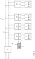
- FIG. 1 shows a lighting system 11 with a central unit 10 which is connected to a mains voltage supply source 21 and an emergency supply voltage source 22, for example.
- the mains voltage supply source provides usual AC voltage
- the emergency supply voltage source usually provides DC voltage by means of a battery or a large number of batteries.
- Supply lines 17, which can also be used to transmit data, are arranged on an output side of the central unit 10. There is also the option of providing a separate data line 18 .
- a large number of lamps 1.1, 1.2, . . . , 1.n are connected in parallel to the supply lines 17. Each of these lights is according to the figure 1 educated. Such a lamp is shown as an example. This has a pictogram 24 on which a display 23 in the form of an "X", for example in red, can be superimposed. This corresponds to an escape sign luminaire, which, for example, through appropriate feedback from the emergency center 9 figure 1 changes its mode, which may also change the load on the LED driver from the LEDs. According to the invention, this load is compensated for by the load balancing device 6, so that the total load relative to the LED driver 3 remains essentially constant, regardless of the mode of the corresponding lamp 1.
- the load balancer can include almost any active or passive component that can serve as an AC or DC electrical load.
- the load balancer can include almost any active or passive component that can serve as an AC or DC electrical load.
- Corresponding passive components are, for example, resistors and active components are transistors such as bipolar transistors, MOSFET transistors or IGBTs, all of which can be used as corresponding electrical loads, with this electrical load being controlled in such a way that a constant load current results overall.
- the load balancer can be placed both on the input side and on the output side of the LED driver. An arrangement on the output side, i.e. on the DC voltage side, is preferred, since it is easier to balance the power consumption of the LED load and the load balancing device there.
- the load balancer takes over a certain part in addition to the LED part of the output current of the LED driver, so this essentially ensures that a corresponding input current of the LED driver does not change even if the mode of the luminaire changes, see Blinking, flashing, dimming or the like.
- the combination of LED load and load balancer forms the corresponding total load, which remains essentially constant. Changing operating modes of the lamp therefore do not affect the load current, so that there is also no influence on a corresponding current pulse communication between the lamp and the central unit.
Landscapes
- Engineering & Computer Science (AREA)
- Power Engineering (AREA)
- Business, Economics & Management (AREA)
- Emergency Management (AREA)
- Circuit Arrangement For Electric Light Sources In General (AREA)
Abstract
Description
- Die Erfindung betrifft eine Leuchte, insbesondere Rettungszeichen-, Sicherheits- oder Notleuchte, mit zumindest einer Anzahl von LEDs, einem LED-Treiber und einer Überwachungs- und Steuereinheit, wobei die Leuchte in verschiedenen auswählbaren Moden einsetzbar ist und wenigstens einen Anschluss zur Spannungsversorgung und zum Datenaustausch aufweist. Solche Leuchten sind in der Regel Teil eines Beleuchtungssystems, beispielsweise in einem Gebäude, wobei die Leuchten über eine Zentraleinheit des Beleuchtungssystems überwacht und versorgt werden. Die verschiedenen Leuchten dienen insbesondere zur Anzeige eines Fluchtwegs, als Sicherheitsbeleuchtung oder dergleichen.
- Die Leuchten sind mit der Zentraleinheit über wenigstens einen Anschluss zur Spannungsversorgung und zum Datenaustausch verbunden. Ein solcher Datenaustausch dient insbesondere dazu, beispielsweise an die Leuchte kurze Strompulse oder Impulssequenzen als Abfrage zu übermitteln, um eine Rückmeldung von der Leuchte hinsichtlich beispielsweise einer Statusinformation der Leuchte zu erhalten. Solche Beleuchtungssysteme sind im Allgemeinen als Zentralsicherheitsbeleuchtungssysteme oder Zentralüberwachungssysteme bekannt. Eine serielle, digitale Information von jeder Last im Beleuchtungssystem wird dekodiert und auf diese Weise ist ein kompletter Status von allen angeschlossenen Lasten abfragbar und speicher- oder darstellbar. Solche Lasten sind die oben genannten Leuchten, wie Sicherheitsleuchten, Rettungszeichenleuchten, Notleuchten, Fluchtwegleuchten oder dergleichen.
- Bei neuen Beleuchtungssystemen müssen die Leuchten zusätzliche Anforderungen erfüllen. Beispielsweise müssen alle Notbeleuchtungssysteme adaptiv und dynamisch entsprechende Rettungs- oder Fluchtwege anzeigen können, um neuen Anforderungen zu genügen. Eine solche Anforderung ist beispielsweise eine entsprechende Reaktion auf eine Feuermeldung oder dergleichen innerhalb des Gebäudes. Das Auftreten eines Feuers kann eine oder mehrere dynamische Änderung/Änderungen eines Fluchtweges und eine entsprechende Anpassung der Fluchtwegleitung erforderlich machen. Dazu werden beispielsweise einzelne Leuchten in anderen Betätigungsoden betrieben, wie Blinkmodus, Aufblitzmodus, Dimmmodus oder Einschalt- oder Ausschaltmodus. Die Betätigungsmoden können mittels Steuerinformationen über separate Steuereingänge an den Leuchten, aber alternativ oder zusätzlich auch über andere Daten- / Informationskanäle wie Funk, Datenleitung oder Versorgungsspannungsbeeinflussung konfiguriert werden.
- Bei einem entsprechenden Modus wird dann analog der Laststrom einer jeden Leuchte pulsieren oder sich in anderer Weise ändern, je nach ausgewähltem Betätigungsmodus. Dieses Pulsieren des Laststroms führt allerdings zu erheblichen Schwierigkeiten bei der obengenannten Kommunikation über Stromimpulse mit den entsprechenden Leuchten. D.h., die entsprechenden Daten-Stromimpulse müssen parallel zu den Last-Stromimpulsen übertragen werden, die beispielsweise ein Aufblitzen oder Blinken der Leuchten ermöglichen. D.h., die entsprechenden Stromimpulse für den Betriebsmodus und Stromimpulse zum Datenaustausch stören sich gegenseitig, so dass unter solchen Bedingungen keine zuverlässige und last- /betätigungsmodeunabhängige entsprechende Dekodierung der von den Leuchten abgefragten Daten möglich ist.
- Es gibt zwar Alternativen zum Datenaustausch, wie beispielsweise sogenannte Power-Line-Kommunikation, wobei diese allerdings mit erheblichem technischen und kostenmäßigem Aufwand verbunden ist.
- Der Erfindung liegt daher die Aufgabe zugrunde, eine Leuchte der eingangs genannten Art in einfacher und kostengünstiger Weise zum Datenaustausch mittels Stromimpulsen auszubilden, wobei jede einzelne Leuchte keinen Einschränkungen hinsichtlich Dauer, Bandbreite oder Zeitsteuerung bei der entsprechenden Übermittlung der Stromimpulse zwischen Leuchte und Zentraleinheit aufweisen soll.
- Nach Erfindung ist es ebenfalls nicht nötig, dass alle im Beleuchtungssystem enthaltenen Leuchten in spezieller Weise in ihren Betriebsmoden synchronisiert werden müssen, um beispielsweise eine entsprechende Stromimpulskommunikation in engen Zeitintervallen durchzuführen, in denen alle Leuchten im gleichen Status sind. Auch eine solche Lösung würde die Bandbreite der Kommunikation erheblich einschränken und erfordert außerdem, dass alle adaptiven oder dynamischen Leuchten eines Endstromkreises im gleichen Operationsmodus sind. Dies ist nicht immer möglich.
- Erfindungsgemäß weist die Leuchte zusätzlich eine Lastausgleichseinrichtung auf, durch welche zusammen mit den LEDs als Gesamtlast eine im Wesentlichen konstante Stromaufnahme der Leuchte und insbesondere des LED-Treibers einstellbar ist.
- Dadurch besteht die Möglichkeit, die Kommunikation zwischen den Leuchten und der Zentraleinheit durch Stromimpulse durchzuführen, was erheblich preiswerter und sicherer ist, als alternative Kommunikationslösungen, siehe beispielsweise die Power-Line-Kommunikation. Die Lastausgleichseinrichtung dient dazu, bei Änderungen des Laststroms durch die LEDs diesen entsprechend auszugleichen, sodass im Wesentlichen ein konstanter Strom fließt bzw. eine gleichbleibende Last simuliert wird. Ist eine Leuchte beispielsweise im Aufblitz- oder Blinkmodus, übernimmt die Lastausgleichseinrichtung den entsprechenden Laststrom während der Ausschaltphasen der entsprechenden LEDs.
- Um die Leuchte in einfacher Weise mit einer entsprechenden Notfallstelle verbinden zu können, kann diese einen insbesondere potentialfreien Anschluss für diese Notfallstelle aufweisen. Eine solche Notfallstelle wäre beispielsweise eine Brandmeldestelle. Erfasst diese einen Brand oder eine andere Gefährdungssituation an einer bestimmten Stelle in einem Gebäude, wird dynamisch beispielsweise eine Fluchtwegleitung geändert, um der Brandstelle bzw. einem Feuer oder anderen Gefahr sicher ausweichen zu können. Dazu werden entsprechende Daten von der Notfallstelle an den Anschluss der Leuchte übermittelt. Diese ändert dann ihren Status in beispielsweise Blinkmodus, Aufblitzmodus oder auch Ausschaltmodus. Es besteht ebenfalls die Möglichkeit, statt eines Ausschaltens der entsprechenden Leuchte beispielsweise ein rotes, kreuzähnliches Piktogramm aufleuchten zu lassen, das eine entsprechende Fluchtrichtungsanzeige einer solchen Leuchte ungültig macht, so dass sich Personen innerhalb des Gebäudes entlang anderer Leuchten, insbesondere Rettungszeichenleuchten und Fluchtwegleuchten, an eine sichere Stelle unter Umgehung des entsprechenden Brand- oder Gefahrenherdes begeben.
- Wie bereits oben ausgeführt, soll auch die erfindungsgemäße Leuchte von der Zentraleinheit des Beleuchtungssystems abfragbar sein. Dies erfolgt entsprechend über die Stromimpulse, Sequenzen von Stromimpulsen oder entsprechender Datenpakete. Diese sind von der Leuchte an die Zentraleinheit übermittelbar.
- Entsprechende Stromimpulse oder Belastungsstromimpulse sind beispielsweise in der
EP 0 980 131 oderEP 1 170 849 beschrieben. Die Erzeugung von einem oder mehreren Stromimpulsen auf einer Versorgungsleitungsverbindung ist in derEP 2 194 762 und eine Anzahl von Belastungsimpulsen sind in derEP 2 704 332 beschrieben. Auch bei der vorliegenden Erfindung kann entsprechend die Übertragung solcher Stromimpulse, Sequenzen von Stromimpulsen oder Datenpaketen in dieser Art erfolgen. - Für die erfindungsgemäße Leuchte sind unterschiedliche Moden denkbar, die beispielsweise aus Blinkmodus, Aufblitzmodus, Dimmmodus, Einschaltmodus, Ausschaltmodus oder dergleichen auswählbar sind.
- Ein entsprechender Modus ist ggf. über eine Eingabe am potenzialfreien Anschluss auswählbar, so dass der entsprechende Modus beispielsweise von der Notfallstelle her initiiert wird.
- Je nach Modus übernimmt die Lastausgleichseinrichtung einen bestimmten Teil der Last, so dass sich insgesamt ein im Wesentlichen konstanter Laststrom ergibt. Ist beispielsweise eine Leuchte im Dimmmodus und verbraucht einen reduzierten Laststrom, so kann die Lastausgleichseinrichtung einen bestimmten Teil-Strom verbrauchen, so dass sich insgesamt ein Laststrom ergibt, der ohne diesen besonderen Modus durch die LEDs der Leuchte fließen würde.
- Erfindungsgemäß besteht die Möglichkeit, siehe auch die obigen Ausführungen, dass auf eine entsprechende Abfrage von Seiten der Zentralstelle/-einheit her, eine Antwort in Form eines Datenpakets von der Leuchte an die Zentralstelle/-einheit übermittelbar ist.
- Die Lastenausgleichseinrichtung kann beispielsweise eine steuerbare Stromsenke sein. Diese ist entsprechend so ausgebildet, dass ein Laststrom in einem definierten Bereich eingestellt wird oder eine entsprechende elektronische Regelung erfolgt, so dass jeweils die Gesamtlast von Lastausgleichseinrichtung und LEDs der Leuchte zu einem im Wesentlichen konstanten Laststrom führt. In diesem Zusammenhang sei noch darauf verwiesen, dass die steuerbare Stromsenke entsprechend zum Verbrauch der Leuchten ausgebildet ist. Beispielsweise haben Rettungszeichenleuchten je nach Größe und Ausbildung einen typischen Verbrauch von 4 bis 12 Watt. Sie verwenden Gruppen mit einer Anzahl von LEDs als Lichtquellen, die normalerweise seriell verbunden sind und mit einem konstanten Strom versorgt werden. Für die oben beschriebenen dynamischen und adaptiven Merkmale ist es erforderlich, dass die Ausgabe des LED-Treibers als Leistungsversorgung ein- oder ausgeschaltet wird oder zumindest die Helligkeit der LEDs durch Pulsbreitenmodulation (PWM) und/oder Konstantstromveränderung modifiziert wird zwischen Werten von 0 % bis 100 %. Entsprechend zu dieser Änderung des Verbrauchs der LEDs wird die Lastausgleichseinrichtung angesteuert und kontrolliert.
- Ein einfaches Ausführungsbeispiel für eine solche steuerbare Stromsenke als Lastausgleichseinrichtung ist eine Stromsenke, welche eine Bypass-Einrichtung und eine Steuerelektronik aufweist. Durch die Bypass-Einrichtung wird Strom, der den LEDs nicht zugeführt wird, im entsprechenden Modus umgeleitet und entsprechend verbraucht, so dass insgesamt eine konstante Stromversorgung von Seiten des LED-Treibers her aufrechterhalten wird.
- Eine entsprechende Bypass-Einrichtung kann eine Schalteinrichtung und einen Lastkreis aufweisen. In einem solchen Lastkreis ist beispielsweise ein Widerstand, ein bipolarer Transistor, ein MOSFET-Transistor, ein IGBT oder dergleichen angeordnet.
- Es besteht die Möglichkeit, die Lastausgleichseinrichtung entweder auf einer Eingangs- oder auch auf einer Ausgangsseite des LED-Treibers anzuordnen. Bevorzugt kann die Lastausgleichseinrichtung auf einer Ausgangsseite des LED-Treibers zwischen diesem und den LEDs verschaltet sein. Dadurch ist es einfacher, den Verbrauch zwischen LEDs und Lastausgleichseinrichtung bzw. Stromsenke auszugleichen.
- In bestimmten Fällen kann es sich von Vorteil erweisen, wenn die Lastausgleichseinrichtung abschaltbar ist. Dies gilt beispielsweise dann, wenn die Leuchte an sich ausgeschaltet ist oder wenn beispielsweise ein Funktionstest der LEDs oder des zugehörigen Treibers stattfindet. Ansonsten wäre eine Beeinflussung der Testergebnisse möglich.
- Weiterhin besteht die Möglichkeit, dass die Lastausgleichseinrichtung direkt ein Umschalten von Einschalt- oder Ausschaltmodus in Blink-, Dimm-, Aufblitzmodus oder der gleichen ermöglicht. Bei einem solchen Umschalten wird dann immer die Lastausgleichseinrichtung aktiv, um zusammen mit den LEDs einen im wesentlichen konstanten Laststrom zu erzeugen.
- Die Erfindung betrifft ebenfalls ein entsprechendes Beleuchtungssystem mit einer Zentraleinheit, die mit Netzspannungs- und Notversorgungsspannungsquelle sowie mit einer Anzahl von Leuchten der vorangehend beschriebenen Art verbunden ist. Die Leuchten sind dabei parallel mit der Zentraleinheit verbunden, wobei dies über zumindest eine Spannungs- und Datenverbindungsleitung erfolgt. Es ist ebenfalls denkbar, dass eine zusätzliche Datenverbindungsleitung vorgesehen ist. Die entsprechende Netzspannung ist eine Wechselspannung und die Notversorgungsspannung ist in der Regel eine Gleichspannung von einer insbesondere aufladbaren Batterie oder dergleichen.
- Im Folgenden wir die Erfindung anhand der beigefügten Figuren näher erläutert.
- Es zeigen:
- Fig. 1 und
- eine erfindungsgemäße Leuchte mit Verbindung zu einer Brandmeldestelle,
- Fig. 2
- eine Vielzahl der Leuchten nach
Figur 1 in einem Beleuchtungssystem mit einer Zentraleinheit. -
Figur 1 zeigt eine Leuchte 1, die mit ihren wesentlichen Bauteilen dargestellt ist. Es fehlen weitere Bauteile, wie beispielsweise ein Gehäuse, ein Piktogramm, optische Bauteile wie beispielsweise Spiegel, eine Lichtverteilplatte oder dergleichen. - Die Leuchte 1 weist zumindest eine Anzahl von LEDs 2 auf, die Licht in einer bestimmten Richtung abgeben. Die LEDs 2 sind mit einem LED-Treiber 3 zur Versorgung verbunden. Außer dem LED-Treiber 3 und den LEDs 2 ist außerdem eine Überwachungs- und Steuereinheit 4 in der Leuchte 1 angeordnet. Über diese erfolgt in der Regel die Überwachung und Steuerung der Leuchte, wobei diese auch über entsprechende Anschlüsse 5 für eine Spannungsleitung 17 mit der Überwachungs- und Steuereinheit 4 verbunden sind. Es besteht die Möglichkeit, dass Daten direkt über die Spannungsleitungen 17 übermittelt werden, wobei zusätzlich ebenfalls eine Datenverbindungsleitung 18 vorgesehen sein kann.
- Je nach Erfordernis, erfolgt die Versorgung innerhalb der Leuchte über Wechselspannung oder Gleichspannung. Zumindest Überwachungs- und Steuereinheit 4 sowie LED-Treiber 3 können in einem gemeinsamen Gehäuse und auf einer Platine angeordnet sein. Erfindungsgemäß erfolgt eine zusätzliche Anordnung einer Lastausgleichseinrichtung 6. Bei dem dargestellten Ausführungsbeispiel ist diese auf einer Sekundärseite 19 des LED-Treibers 3 angeordnet. Die Lastausgleichseinrichtung 6 weist neben entsprechenden Anschlüssen für Daten einen Steueranschluss für eine Kommunikation mit dem LED-Treiber auf.
- Von der Lastausgleichseinrichtung 6 erfolgt die entsprechende weitere Spannungsversorgung der LEDs 2. Insgesamt bilden Lastausgleichseinrichtung 6 und LEDs 2 eine Gesamtlast 7. Diese setzt sich aus den Einzellasten von Lastausgleichseinrichtung 6 bzw. LEDs 2 zusammen. Sind die LEDs in ihrem Normalbetrieb, wird im Prinzip die Gesamtlast von den LEDs bereitgestellt, ohne dass die Lastausgleichseinrichtung 6 eine weitere Last bildet. In umgekehrter Weise kann beispielsweise bei einem Blinkbetrieb, bei dem die LEDs 2 zumindest periodisch ausgeschaltet sind, in diesen Ausschaltphasen die Lastausgleichseinrichtung 6 die Gesamtlast bilden. Dadurch ist im Hinblick auf den LED-Treiber 3 im Wesentlichen sichergestellt, dass dieser immer eine Gesamtlast mit im wesentlichen konstantem Strom versorgen kann.
- Die Leuchte 1 weist weiterhin einen Anschluss 8 für eine Notfallstelle 9 auf. Dies ist beispielsweise eine Brandmeldestelle, die über insbesondere potentialfreie Anschlüsse mit dem entsprechenden potentialfreien Anschluss 8 an der Leuchte 1 verbunden ist. Es besteht ebenfalls die Möglichkeit, die Verbindung zwischen Notfallstelle 9 und Leuchte 1 an einer anderen Stelle zusätzlich oder alternativ herzustellen, siehe bspw. entsprechende Anschlüsse 8 zur Verbindung von Notfallstelle 9 und LED-Treiber 3.
- Im Wesentlichen sind LED-Treiber 3 und Überwachungs- und Steuereinheit 4 üblicherweise ausgebildet, ohne entsprechende Modifikationen für die erfindungsgemäße Leuchte. Die erfindungsgemäße Leuchte weist insbesondere die Lastausgleichseinrichtung 6 auf, die beispielsweise als steuerbare Stromsenke 12 ausgebildet ist. Eine solche steuerbare Stromsenke kann eine Bypass-Einrichtung 13 und eine Steuerelektronik 14 aufweisen. Die Bypass-Einrichtung 13 weist eine Schalteinrichtung 15 und einen Lastkreis 16 auf. Dieser umfasst beispielsweise einen Widerstand oder einen entsprechenden Transistor, wie Bipolar-Transistor, MOSFET-Transistor, IGBT oder dergleichen. Über die Schalteinrichtung 15 ist bei dem dargestellten Ausführungsbeispiel der Lastkreis 16 einschaltbar, so dass die Lastausgleichseinrichtung 6 einen gewissen Laststrom verbraucht. Es besteht ebenfalls die Möglichkeit, die LEDs vollständig kurzzuschließen, so dass die Gesamtlast durch die Lastausgleichseinrichtung 6 bereitgestellt wird. Weiterhin besteht die Möglichkeit, beispielsweise die Lastausgleichseinrichtung 6 kurzzuschließen oder auszuschalten, so dass die Gesamtlast durch die LEDs 2 gebildet wird.
- Die Steuerelektronik 14 dient dazu, die Bypass-Einrichtung entsprechend zu schalten, insbesondere im Hinblick auf einen Moduswechsel der LEDs, der ggf. von der Notfallstelle 9 her initiiert wird.
- Erfindungsgemäß besteht ebenfalls die Möglichkeit, kontinuierliche Änderungen der Last aus Seiten der LEDs entsprechend kontinuierlich durch die Lastausgleichseinrichtung 6 mittels der entsprechenden Steuerelektronik 14 auszugleichen.
-
Figur 2 zeigt ein Beleuchtungssystem 11 mit einer Zentraleinheit 10, die beispielsweise mit einer Netzspannungsversorgungquelle 21 und einer Notversorgungsspannungsquelle 22 verbunden ist. Die Netzspannungsversorgungquelle stellt übliche Wechselspannung parat, während von der Notversorgungsspannungsquelle in der Regel Gleichspannung mittels einer Batterie oder einer Vielzahl von Batterien bereitgestellt wird. Auf einer Ausgangsseite der Zentraleinheit 10 sind Versorgungsleitungen 17 angeordnet, die ebenfalls zur Übertragung von Daten verwendet werden können. Es besteht weiterhin die Möglichkeit, eine separate Datenleitung 18 vorzusehen. - Mit den Versorgungsleitungen 17 sind eine Vielzahl von Leuchten 1.1, 1.2, ..., 1.n parallel verbunden. Jede dieser Leuchten ist entsprechend zur
Figur 1 ausgebildet. Eine solche Leuchte ist beispielhaft dargestellt. Diese weist ein Piktogramm 24 auf, dem eine Anzeige 23 in Form eines "X" beispielsweise in roter Farbe überlagerbar ist. Dies entspricht einer Rettungszeichenleuchte, die beispielsweise durch entsprechende Rückmeldung von der Notfallstelle 9 nachFigur 1 ihren Modus ändert, wodurch ggf. auch die Belastung des LED-Treibers von den LEDs her verändert wird. Diese Belastung wird erfindungsgemäß durch die Lastausgleichseinrichtung 6 ausgeglichen, so dass unabhängig vom Modus der entsprechenden Leuchte 1 die Gesamtlast relativ zum LED-Treiber 3 im Wesentlichen konstant bleibt. - Jede der Leuchten 1.1, 1.2, ..., 1.n weist als eine erste Last die LEDs 2 und als eine zweite Last die Lastausgleichseinrichtung 6 in Form einer steuerbaren Stromsenke 12 auf, siehe Figur 1. An dieser Stelle sei nochmals angemerkt, dass die Lastausgleichseinrichtung nahezu jede aktive oder passive Komponente beinhalten kann, die als elektrische Last für Wechselspannung oder Gleichspannung dienen kann. Entsprechende passive Komponenten sind beispielsweise Widerstände und aktive Komponenten sind Transistoren wie Bipolar-Transistor, MOSFET-Transistor oder IGBT, die alle als entsprechende elektrische Last einsetzbar sind, wobei diese elektrische Last so gesteuert wird, dass sich insgesamt ein konstanter Laststrom ergibt. Die Lastausgleichseinrichtung kann sowohl auf der Eingangsseite als auch auf der Ausgangsseite des LED-Treibers angeordnet werden. Bevorzug ist eine Anordnung auf der Ausgangsseite, d.h., auf der Gleichspannungsseite, da dort ein Ausgleich zwischen Leistungsverbrauch von LED-Last und Lastausgleichseinrichtung einfacher durchzuführen ist.
- Durch die Lastausgleichseinrichtung wird ein bestimmter Teil zusätzlich zum LED-Teil des Ausgabestroms des LED-Treibers übernommen, so dass dadurch im Wesentlichen sichergestellt ist, dass ein entsprechender Eingangsstrom des LED-Treibers sich nicht ändert, selbst wenn sich der Modus der Leuchte ändert, siehe Blinken, Aufblitzen, Dimmen oder dergleichen. Die Kombination aus LED-Last und Lastausgleichseinrichtung bildet die entsprechende Gesamtlast, die im Wesentlichen konstant bleibt. Sich ändernde Betriebsmoden der Leuchte wirken somit nicht auf den Laststrom zurück, so dass ebenfalls keine Beeinflussung einer entsprechenden Stromimpulskommunikation zwischen Leuchte und Zentraleinheit erfolgt.
Claims (15)
- Leuchte (1, 1.1, 1.2, ..., 1.n), insbesondere Rettungszeichen- Sicherheits- oder Notleuchte, mit zumindest einer Anzahl von LEDs (2), einem LED-Treiber (3) und einer Überwachungs- und Steuereinheit (4), wobei die Leuchte (1, 1.1, 1.2,..., 1.n) in verschiedenen und auswählbaren Moden einsetzbar ist sowie wenigstens einen Anschluss (5) zur Spannungsversorgung und zum Datenaustausch aufweist, dadurch gekennzeichnet, dass die Leuchte (1, 1.1, 1.2, ..., 1.n) eine Lastausgleichseinrichtung (6) aufweist, durch welche zusammen mit den LEDs (2) als Gesamtlast (7) eine im Wesentlichen konstante Stromaufnahme der Leuchte und insbesondere des LED-Treibers einstellbar ist.
- Leuchte nach Anspruch 1, dadurch gekennzeichnet, dass die Leuchte (1, 1.1, 1.2, ..., 1.n) einen insbesondere potentialfreien Anschluss (8) für eine Notfallstelle (9) aufweist.
- Leuchte nach Anspruch 1 oder 2, dadurch gekennzeichnet, dass die Leuchte (1, 1.1, 1.2, ..., 1.n) von einer Zentraleinheit (10) eines Beleuchtungssystems (11) abfragbar ist.
- Leuchte nach Anspruch 3, dadurch gekennzeichnet, dass zur Beantwortung der Abfrage kurze Stromimpulse oder Stromimpulssequenzen von der Leuchte (1, 1.1, 1.2, ..., 1.n) zur Zentraleinheit (10) übermittelbar sind.
- Leuchte nach einem der vorangehenden Ansprüche, dadurch gekennzeichnet, dass ein Modus der Leuchte (1, 1.1, 1.2, ..., 1.n) auswählbar ist aus Blinkmodus, Aufblitzmodus, Dimmmodus, Einschaltmodus, Ausschaltmodus oder dergleichen.
- Leuchte nach einem der vorangehenden Ansprüche, dadurch gekennzeichnet, dass mittels einer Eingabe am potentialfreien Anschluss (8) ein Modus auswählbar ist.
- Leuchte nach Anspruch 3, dadurch gekennzeichnet, dass die Abfragebeantwortung in Form eines Datenpakets übermittelbar ist.
- Leuchte nach einem der vorangehenden Ansprüche, dadurch gekennzeichnet, dass die Lastausgleichseinrichtung (6) eine steuerbare Stromsenke (12) ist.
- Leuchte nach Anspruch 8, dadurch gekennzeichnet, dass die steuerbare Stromsenke (12) zumindest eine Bypass-Einrichtung (13) und eine Steuerelektronik (14) aufweist.
- Leuchte nach Anspruch 9, dadurch gekennzeichnet, dass die Bypass-Einrichtung (13) eine Schalteinrichtung (15) und einen Lastkreis (16) aufweist.
- Leuchte nach einem der vorangehenden Ansprüche, dadurch gekennzeichnet, dass die Lastausgleichseinrichtung (6) auf einer Sekundärseite (19) des LED-Treibers (3) zwischen diesem und den LEDs (2) verschaltet ist.
- Leuchte nach einem der vorangehenden Ansprüche, dadurch gekennzeichnet, dass die Lastausgleichseinrichtung (6) abschaltbar ist.
- Leuchte nach einem der vorangehenden Ansprüche, dadurch gekennzeichnet, dass die Lastausgleichseinrichtung (6) umschaltbar ist abhängig von Einschalt- oder Ausschaltmodus der LEDs oder Blink-, Dimm-, Aufblitzmodus oder dergleichen der LEDs.
- Leuchte nach einem der vorangehenden Ansprüche, dadurch gekennzeichnet, dass die Betätigungsmoden mittels Steuerinformation über separate Steuereingänge an den Leuchten und/oder über andere Daten-/ Informationskanäle wie Funk, Datenleitung oder Versorgungsspannungsbeeinflussung konfigurierbar sind.
- Beleuchtungssystem (11) mit einer Zentraleinheit (10), die mit Netzspannungs- und Notversorgungsspannungsquelle eingangsseitig sowie mit einer Vielzahl von Leuchten (1) nach einem der vorangehenden Ansprüche ausgangsseitig verbunden ist, wobei die Leuchten (1, 1.1, 1.2, ..., 1.n) parallel mit der Zentraleinheit (10) über Spannungs- und Datenverbindungsleitung verbunden sind.
Applications Claiming Priority (1)
| Application Number | Priority Date | Filing Date | Title |
|---|---|---|---|
| DE102020209562.0A DE102020209562A1 (de) | 2020-07-29 | 2020-07-29 | Leuchte und Beleuchtungssystem |
Publications (2)
| Publication Number | Publication Date |
|---|---|
| EP3945750A1 true EP3945750A1 (de) | 2022-02-02 |
| EP3945750B1 EP3945750B1 (de) | 2024-01-17 |
Family
ID=75302382
Family Applications (1)
| Application Number | Title | Priority Date | Filing Date |
|---|---|---|---|
| EP21166013.9A Active EP3945750B1 (de) | 2020-07-29 | 2021-03-30 | Leuchte und beleuchtungssystem |
Country Status (2)
| Country | Link |
|---|---|
| EP (1) | EP3945750B1 (de) |
| DE (1) | DE102020209562A1 (de) |
Citations (8)
| Publication number | Priority date | Publication date | Assignee | Title |
|---|---|---|---|---|
| EP0980131A2 (de) | 1998-08-10 | 2000-02-16 | CEAG Sicherheitstechnik GmbH | Verfahren und Überwachungsvorrichtung zur Überwachung wenigstens eines von zur Notversorgung von elektrischen und/oder elektronischen Verbrauchern zuschaltbaren Batteriesatzes |
| EP1170849A2 (de) | 2000-06-14 | 2002-01-09 | CEAG Sicherheitstechnik GmbH | Verfahren zur Steuerung und entsprechende Schaltungsanordnung |
| EP2194762A1 (de) | 2008-12-05 | 2010-06-09 | CEAG Notlichtsysteme GmbH | Verfahren und Vorrichtung zur Steuerung und Überwachung eines Not- oder Sicherheitsbeleuchtungssystem |
| US20110068702A1 (en) * | 2009-09-24 | 2011-03-24 | Cree Led Lighting Solutions, Inc. | Solid state lighting apparatus with controllable bypass circuits and methods of operation thereof |
| EP2547174A2 (de) * | 2011-07-15 | 2013-01-16 | Panasonic Corporation | Beleuchtung zur Kommunikation, und Beleuchtungsvorrichtung und System |
| DE102012101950A1 (de) * | 2012-03-08 | 2013-09-12 | Rp-Technik E.K. | Rettungszeichenleuchte, insbesondere für die Installation in elektrifizierten Bahntunneln |
| EP2704332A2 (de) | 2012-08-31 | 2014-03-05 | CEAG Notlichtsysteme GmbH | Not-/Sicherheitsbeleuchtungsanlage und Verfahren zu deren Steuerung |
| WO2016191781A1 (de) * | 2015-06-01 | 2016-12-08 | Zkw Group Gmbh | Beleuchtungseinrichtung für fahrzeuge |
Family Cites Families (3)
| Publication number | Priority date | Publication date | Assignee | Title |
|---|---|---|---|---|
| DE10149860A1 (de) | 2001-10-10 | 2003-04-24 | Axsyn Gmbh I Ins | Sicherheitsleuchten für Fluchtwege und ein Lichtleitsystem zur Steuerung dieser Sicherheitsleuchten |
| DE102006018308B4 (de) | 2006-04-20 | 2019-05-09 | HELLA GmbH & Co. KGaA | Schaltungsanordnung für ein Fahrzeugbordnetz zum Simulieren von Blinkleuchten mit Glühlampen bei einer Verwendung von Blinkleuchten mit Leuchtdioden |
| DE102013001194A1 (de) | 2013-01-24 | 2014-07-24 | Jakob Löschke | LED-Modul. LED-Vorschaltvorrichtung und System aus einem LED-Modul und einer LED-Vorschaltvorrichtung |
-
2020
- 2020-07-29 DE DE102020209562.0A patent/DE102020209562A1/de not_active Ceased
-
2021
- 2021-03-30 EP EP21166013.9A patent/EP3945750B1/de active Active
Patent Citations (8)
| Publication number | Priority date | Publication date | Assignee | Title |
|---|---|---|---|---|
| EP0980131A2 (de) | 1998-08-10 | 2000-02-16 | CEAG Sicherheitstechnik GmbH | Verfahren und Überwachungsvorrichtung zur Überwachung wenigstens eines von zur Notversorgung von elektrischen und/oder elektronischen Verbrauchern zuschaltbaren Batteriesatzes |
| EP1170849A2 (de) | 2000-06-14 | 2002-01-09 | CEAG Sicherheitstechnik GmbH | Verfahren zur Steuerung und entsprechende Schaltungsanordnung |
| EP2194762A1 (de) | 2008-12-05 | 2010-06-09 | CEAG Notlichtsysteme GmbH | Verfahren und Vorrichtung zur Steuerung und Überwachung eines Not- oder Sicherheitsbeleuchtungssystem |
| US20110068702A1 (en) * | 2009-09-24 | 2011-03-24 | Cree Led Lighting Solutions, Inc. | Solid state lighting apparatus with controllable bypass circuits and methods of operation thereof |
| EP2547174A2 (de) * | 2011-07-15 | 2013-01-16 | Panasonic Corporation | Beleuchtung zur Kommunikation, und Beleuchtungsvorrichtung und System |
| DE102012101950A1 (de) * | 2012-03-08 | 2013-09-12 | Rp-Technik E.K. | Rettungszeichenleuchte, insbesondere für die Installation in elektrifizierten Bahntunneln |
| EP2704332A2 (de) | 2012-08-31 | 2014-03-05 | CEAG Notlichtsysteme GmbH | Not-/Sicherheitsbeleuchtungsanlage und Verfahren zu deren Steuerung |
| WO2016191781A1 (de) * | 2015-06-01 | 2016-12-08 | Zkw Group Gmbh | Beleuchtungseinrichtung für fahrzeuge |
Also Published As
| Publication number | Publication date |
|---|---|
| EP3945750B1 (de) | 2024-01-17 |
| DE102020209562A1 (de) | 2022-02-03 |
Similar Documents
| Publication | Publication Date | Title |
|---|---|---|
| DE69826825T2 (de) | Schaltungsanordnung und zugehörige signalleuchte | |
| DE102004002026A1 (de) | Ansteuerung von Leuchtmittel-Betriebsgeräten über einen modulierten DC-Bus | |
| WO2012163641A1 (de) | Signalisierungsvorrichtung und sensorvorrichtung | |
| DE112010002532T5 (de) | Schaltkreistopologie zum Betreiben von hintereinander geschaltenen Hochspannungs-LED-Reihen | |
| DE202008002883U1 (de) | Schaltung zur Ansteuerung mindestens einer Leuchteinheit und Leuchte | |
| DE102010008275B4 (de) | Vorrichtung zur Energieversorgung von mehreren LED-Einheiten | |
| EP3351056B1 (de) | Versorgungseinheit für einen bus | |
| EP1858301A1 (de) | LED-Beleuchtungssystem und -verfahren zur Erzeugung einer vorgebbaren Farbsequenz | |
| DE112013006888T5 (de) | Vorrichtung zum Betreiben vielfarbiger LED-Bänder | |
| EP3945750B1 (de) | Leuchte und beleuchtungssystem | |
| DE102010052661B3 (de) | Kommunikationssystem zur Steuerung von elektrischen Lasten | |
| EP2280585B1 (de) | Verfahren zur Einstellung der Ansteuerung mehrerer Leuchten | |
| EP1619935B1 (de) | Notlichtvorschaltelement mit digital adressierbarer Steuerschnittstelle | |
| EP1351366A2 (de) | Leuchte | |
| DE3524681C2 (de) | ||
| EP1271745B1 (de) | Verfahren zum Betrieb elektrischer Endverbraucher sowie eine Einrichtung zur Durchführung des Verfahrens | |
| EP2625930B1 (de) | Betriebsgerät mit einstellbarer kritischer temperatur | |
| EP0471331A1 (de) | Schaltungsanordnung für den Betrieb einer Leuchtstofflampe | |
| EP0903966B1 (de) | Beleuchtungssystem | |
| DE602005004167T2 (de) | Elektrische Schaltung für LED Signallampen mit einer Schaltschwelle zum Umschalten zwischen Tages- und Nachtbetrieb | |
| EP2282610A2 (de) | Verfahren zur Ansteuerung einer Leuchte | |
| EP2704332A2 (de) | Not-/Sicherheitsbeleuchtungsanlage und Verfahren zu deren Steuerung | |
| DE102019117472A1 (de) | Treiber, Verfahren zur Steuerung des Treibers, und Beleuchtungsmodul | |
| EP1555857B1 (de) | Zentrale Versorgung über mehrere DC-Ausgangskreise | |
| DE102011008572A1 (de) | Zentralversorgungssystem und Verfahren zum gleichzeitigen Dimmen einer Vielzahl von Leuchten |
Legal Events
| Date | Code | Title | Description |
|---|---|---|---|
| PUAI | Public reference made under article 153(3) epc to a published international application that has entered the european phase |
Free format text: ORIGINAL CODE: 0009012 |
|
| STAA | Information on the status of an ep patent application or granted ep patent |
Free format text: STATUS: THE APPLICATION HAS BEEN PUBLISHED |
|
| AK | Designated contracting states |
Kind code of ref document: A1 Designated state(s): AL AT BE BG CH CY CZ DE DK EE ES FI FR GB GR HR HU IE IS IT LI LT LU LV MC MK MT NL NO PL PT RO RS SE SI SK SM TR |
|
| STAA | Information on the status of an ep patent application or granted ep patent |
Free format text: STATUS: REQUEST FOR EXAMINATION WAS MADE |
|
| 17P | Request for examination filed |
Effective date: 20220729 |
|
| RBV | Designated contracting states (corrected) |
Designated state(s): AL AT BE BG CH CY CZ DE DK EE ES FI FR GB GR HR HU IE IS IT LI LT LU LV MC MK MT NL NO PL PT RO RS SE SI SK SM TR |
|
| STAA | Information on the status of an ep patent application or granted ep patent |
Free format text: STATUS: EXAMINATION IS IN PROGRESS |
|
| 17Q | First examination report despatched |
Effective date: 20221019 |
|
| P01 | Opt-out of the competence of the unified patent court (upc) registered |
Effective date: 20230521 |
|
| RIC1 | Information provided on ipc code assigned before grant |
Ipc: H02J 13/00 20060101ALI20230804BHEP Ipc: H02J 9/02 20060101ALI20230804BHEP Ipc: H05B 47/175 20200101ALI20230804BHEP Ipc: H05B 47/21 20200101ALI20230804BHEP Ipc: H05B 47/17 20200101ALI20230804BHEP Ipc: H05B 45/35 20200101ALI20230804BHEP Ipc: H05B 45/345 20200101AFI20230804BHEP |
|
| GRAP | Despatch of communication of intention to grant a patent |
Free format text: ORIGINAL CODE: EPIDOSNIGR1 |
|
| STAA | Information on the status of an ep patent application or granted ep patent |
Free format text: STATUS: GRANT OF PATENT IS INTENDED |
|
| INTG | Intention to grant announced |
Effective date: 20230921 |
|
| GRAS | Grant fee paid |
Free format text: ORIGINAL CODE: EPIDOSNIGR3 |
|
| GRAA | (expected) grant |
Free format text: ORIGINAL CODE: 0009210 |
|
| STAA | Information on the status of an ep patent application or granted ep patent |
Free format text: STATUS: THE PATENT HAS BEEN GRANTED |
|
| AK | Designated contracting states |
Kind code of ref document: B1 Designated state(s): AL AT BE BG CH CY CZ DE DK EE ES FI FR GB GR HR HU IE IS IT LI LT LU LV MC MK MT NL NO PL PT RO RS SE SI SK SM TR |
|
| REG | Reference to a national code |
Ref country code: GB Ref legal event code: FG4D Free format text: NOT ENGLISH |
|
| REG | Reference to a national code |
Ref country code: DE Ref legal event code: R096 Ref document number: 502021002466 Country of ref document: DE |
|
| REG | Reference to a national code |
Ref country code: CH Ref legal event code: EP |
|
| REG | Reference to a national code |
Ref country code: IE Ref legal event code: FG4D Free format text: LANGUAGE OF EP DOCUMENT: GERMAN |
|
| REG | Reference to a national code |
Ref country code: NL Ref legal event code: FP |
|
| REG | Reference to a national code |
Ref country code: LT Ref legal event code: MG9D |
|
| PG25 | Lapsed in a contracting state [announced via postgrant information from national office to epo] |
Ref country code: IS Free format text: LAPSE BECAUSE OF FAILURE TO SUBMIT A TRANSLATION OF THE DESCRIPTION OR TO PAY THE FEE WITHIN THE PRESCRIBED TIME-LIMIT Effective date: 20240517 |
|
| PG25 | Lapsed in a contracting state [announced via postgrant information from national office to epo] |
Ref country code: LT Free format text: LAPSE BECAUSE OF FAILURE TO SUBMIT A TRANSLATION OF THE DESCRIPTION OR TO PAY THE FEE WITHIN THE PRESCRIBED TIME-LIMIT Effective date: 20240117 |
|
| PG25 | Lapsed in a contracting state [announced via postgrant information from national office to epo] |
Ref country code: GR Free format text: LAPSE BECAUSE OF FAILURE TO SUBMIT A TRANSLATION OF THE DESCRIPTION OR TO PAY THE FEE WITHIN THE PRESCRIBED TIME-LIMIT Effective date: 20240418 |
|
| PG25 | Lapsed in a contracting state [announced via postgrant information from national office to epo] |
Ref country code: HR Free format text: LAPSE BECAUSE OF FAILURE TO SUBMIT A TRANSLATION OF THE DESCRIPTION OR TO PAY THE FEE WITHIN THE PRESCRIBED TIME-LIMIT Effective date: 20240117 Ref country code: RS Free format text: LAPSE BECAUSE OF FAILURE TO SUBMIT A TRANSLATION OF THE DESCRIPTION OR TO PAY THE FEE WITHIN THE PRESCRIBED TIME-LIMIT Effective date: 20240417 |
|
| PG25 | Lapsed in a contracting state [announced via postgrant information from national office to epo] |
Ref country code: ES Free format text: LAPSE BECAUSE OF FAILURE TO SUBMIT A TRANSLATION OF THE DESCRIPTION OR TO PAY THE FEE WITHIN THE PRESCRIBED TIME-LIMIT Effective date: 20240117 |
|
| PG25 | Lapsed in a contracting state [announced via postgrant information from national office to epo] |
Ref country code: RS Free format text: LAPSE BECAUSE OF FAILURE TO SUBMIT A TRANSLATION OF THE DESCRIPTION OR TO PAY THE FEE WITHIN THE PRESCRIBED TIME-LIMIT Effective date: 20240417 Ref country code: LT Free format text: LAPSE BECAUSE OF FAILURE TO SUBMIT A TRANSLATION OF THE DESCRIPTION OR TO PAY THE FEE WITHIN THE PRESCRIBED TIME-LIMIT Effective date: 20240117 Ref country code: IS Free format text: LAPSE BECAUSE OF FAILURE TO SUBMIT A TRANSLATION OF THE DESCRIPTION OR TO PAY THE FEE WITHIN THE PRESCRIBED TIME-LIMIT Effective date: 20240517 Ref country code: HR Free format text: LAPSE BECAUSE OF FAILURE TO SUBMIT A TRANSLATION OF THE DESCRIPTION OR TO PAY THE FEE WITHIN THE PRESCRIBED TIME-LIMIT Effective date: 20240117 Ref country code: GR Free format text: LAPSE BECAUSE OF FAILURE TO SUBMIT A TRANSLATION OF THE DESCRIPTION OR TO PAY THE FEE WITHIN THE PRESCRIBED TIME-LIMIT Effective date: 20240418 Ref country code: FI Free format text: LAPSE BECAUSE OF FAILURE TO SUBMIT A TRANSLATION OF THE DESCRIPTION OR TO PAY THE FEE WITHIN THE PRESCRIBED TIME-LIMIT Effective date: 20240117 Ref country code: ES Free format text: LAPSE BECAUSE OF FAILURE TO SUBMIT A TRANSLATION OF THE DESCRIPTION OR TO PAY THE FEE WITHIN THE PRESCRIBED TIME-LIMIT Effective date: 20240117 Ref country code: BG Free format text: LAPSE BECAUSE OF FAILURE TO SUBMIT A TRANSLATION OF THE DESCRIPTION OR TO PAY THE FEE WITHIN THE PRESCRIBED TIME-LIMIT Effective date: 20240117 |
|
| PG25 | Lapsed in a contracting state [announced via postgrant information from national office to epo] |
Ref country code: PL Free format text: LAPSE BECAUSE OF FAILURE TO SUBMIT A TRANSLATION OF THE DESCRIPTION OR TO PAY THE FEE WITHIN THE PRESCRIBED TIME-LIMIT Effective date: 20240117 Ref country code: PT Free format text: LAPSE BECAUSE OF FAILURE TO SUBMIT A TRANSLATION OF THE DESCRIPTION OR TO PAY THE FEE WITHIN THE PRESCRIBED TIME-LIMIT Effective date: 20240517 |
|
| PG25 | Lapsed in a contracting state [announced via postgrant information from national office to epo] |
Ref country code: SE Free format text: LAPSE BECAUSE OF FAILURE TO SUBMIT A TRANSLATION OF THE DESCRIPTION OR TO PAY THE FEE WITHIN THE PRESCRIBED TIME-LIMIT Effective date: 20240117 Ref country code: PT Free format text: LAPSE BECAUSE OF FAILURE TO SUBMIT A TRANSLATION OF THE DESCRIPTION OR TO PAY THE FEE WITHIN THE PRESCRIBED TIME-LIMIT Effective date: 20240517 Ref country code: PL Free format text: LAPSE BECAUSE OF FAILURE TO SUBMIT A TRANSLATION OF THE DESCRIPTION OR TO PAY THE FEE WITHIN THE PRESCRIBED TIME-LIMIT Effective date: 20240117 Ref country code: LV Free format text: LAPSE BECAUSE OF FAILURE TO SUBMIT A TRANSLATION OF THE DESCRIPTION OR TO PAY THE FEE WITHIN THE PRESCRIBED TIME-LIMIT Effective date: 20240117 |
|
| PG25 | Lapsed in a contracting state [announced via postgrant information from national office to epo] |
Ref country code: DK Free format text: LAPSE BECAUSE OF FAILURE TO SUBMIT A TRANSLATION OF THE DESCRIPTION OR TO PAY THE FEE WITHIN THE PRESCRIBED TIME-LIMIT Effective date: 20240117 |
|
| PG25 | Lapsed in a contracting state [announced via postgrant information from national office to epo] |
Ref country code: SM Free format text: LAPSE BECAUSE OF FAILURE TO SUBMIT A TRANSLATION OF THE DESCRIPTION OR TO PAY THE FEE WITHIN THE PRESCRIBED TIME-LIMIT Effective date: 20240117 |
|
| REG | Reference to a national code |
Ref country code: DE Ref legal event code: R097 Ref document number: 502021002466 Country of ref document: DE |
|
| PG25 | Lapsed in a contracting state [announced via postgrant information from national office to epo] |
Ref country code: EE Free format text: LAPSE BECAUSE OF FAILURE TO SUBMIT A TRANSLATION OF THE DESCRIPTION OR TO PAY THE FEE WITHIN THE PRESCRIBED TIME-LIMIT Effective date: 20240117 Ref country code: CZ Free format text: LAPSE BECAUSE OF FAILURE TO SUBMIT A TRANSLATION OF THE DESCRIPTION OR TO PAY THE FEE WITHIN THE PRESCRIBED TIME-LIMIT Effective date: 20240117 |
|
| PG25 | Lapsed in a contracting state [announced via postgrant information from national office to epo] |
Ref country code: SK Free format text: LAPSE BECAUSE OF FAILURE TO SUBMIT A TRANSLATION OF THE DESCRIPTION OR TO PAY THE FEE WITHIN THE PRESCRIBED TIME-LIMIT Effective date: 20240117 |
|
| PG25 | Lapsed in a contracting state [announced via postgrant information from national office to epo] |
Ref country code: SM Free format text: LAPSE BECAUSE OF FAILURE TO SUBMIT A TRANSLATION OF THE DESCRIPTION OR TO PAY THE FEE WITHIN THE PRESCRIBED TIME-LIMIT Effective date: 20240117 Ref country code: SK Free format text: LAPSE BECAUSE OF FAILURE TO SUBMIT A TRANSLATION OF THE DESCRIPTION OR TO PAY THE FEE WITHIN THE PRESCRIBED TIME-LIMIT Effective date: 20240117 Ref country code: RO Free format text: LAPSE BECAUSE OF FAILURE TO SUBMIT A TRANSLATION OF THE DESCRIPTION OR TO PAY THE FEE WITHIN THE PRESCRIBED TIME-LIMIT Effective date: 20240117 Ref country code: EE Free format text: LAPSE BECAUSE OF FAILURE TO SUBMIT A TRANSLATION OF THE DESCRIPTION OR TO PAY THE FEE WITHIN THE PRESCRIBED TIME-LIMIT Effective date: 20240117 Ref country code: DK Free format text: LAPSE BECAUSE OF FAILURE TO SUBMIT A TRANSLATION OF THE DESCRIPTION OR TO PAY THE FEE WITHIN THE PRESCRIBED TIME-LIMIT Effective date: 20240117 Ref country code: CZ Free format text: LAPSE BECAUSE OF FAILURE TO SUBMIT A TRANSLATION OF THE DESCRIPTION OR TO PAY THE FEE WITHIN THE PRESCRIBED TIME-LIMIT Effective date: 20240117 |
|
| PG25 | Lapsed in a contracting state [announced via postgrant information from national office to epo] |
Ref country code: LU Free format text: LAPSE BECAUSE OF NON-PAYMENT OF DUE FEES Effective date: 20240330 |
|
| PG25 | Lapsed in a contracting state [announced via postgrant information from national office to epo] |
Ref country code: MC Free format text: LAPSE BECAUSE OF FAILURE TO SUBMIT A TRANSLATION OF THE DESCRIPTION OR TO PAY THE FEE WITHIN THE PRESCRIBED TIME-LIMIT Effective date: 20240117 |
|
| PLBE | No opposition filed within time limit |
Free format text: ORIGINAL CODE: 0009261 |
|
| STAA | Information on the status of an ep patent application or granted ep patent |
Free format text: STATUS: NO OPPOSITION FILED WITHIN TIME LIMIT |
|
| PG25 | Lapsed in a contracting state [announced via postgrant information from national office to epo] |
Ref country code: MC Free format text: LAPSE BECAUSE OF FAILURE TO SUBMIT A TRANSLATION OF THE DESCRIPTION OR TO PAY THE FEE WITHIN THE PRESCRIBED TIME-LIMIT Effective date: 20240117 Ref country code: LU Free format text: LAPSE BECAUSE OF NON-PAYMENT OF DUE FEES Effective date: 20240330 |
|
| PG25 | Lapsed in a contracting state [announced via postgrant information from national office to epo] |
Ref country code: IT Free format text: LAPSE BECAUSE OF FAILURE TO SUBMIT A TRANSLATION OF THE DESCRIPTION OR TO PAY THE FEE WITHIN THE PRESCRIBED TIME-LIMIT Effective date: 20240117 |
|
| REG | Reference to a national code |
Ref country code: BE Ref legal event code: MM Effective date: 20240331 |
|
| 26N | No opposition filed |
Effective date: 20241018 |
|
| PG25 | Lapsed in a contracting state [announced via postgrant information from national office to epo] |
Ref country code: IT Free format text: LAPSE BECAUSE OF FAILURE TO SUBMIT A TRANSLATION OF THE DESCRIPTION OR TO PAY THE FEE WITHIN THE PRESCRIBED TIME-LIMIT Effective date: 20240117 |
|
| PG25 | Lapsed in a contracting state [announced via postgrant information from national office to epo] |
Ref country code: BE Free format text: LAPSE BECAUSE OF NON-PAYMENT OF DUE FEES Effective date: 20240331 |
|
| PG25 | Lapsed in a contracting state [announced via postgrant information from national office to epo] |
Ref country code: IE Free format text: LAPSE BECAUSE OF NON-PAYMENT OF DUE FEES Effective date: 20240330 |
|
| PG25 | Lapsed in a contracting state [announced via postgrant information from national office to epo] |
Ref country code: IE Free format text: LAPSE BECAUSE OF NON-PAYMENT OF DUE FEES Effective date: 20240330 Ref country code: BE Free format text: LAPSE BECAUSE OF NON-PAYMENT OF DUE FEES Effective date: 20240331 |
|
| PG25 | Lapsed in a contracting state [announced via postgrant information from national office to epo] |
Ref country code: SI Free format text: LAPSE BECAUSE OF FAILURE TO SUBMIT A TRANSLATION OF THE DESCRIPTION OR TO PAY THE FEE WITHIN THE PRESCRIBED TIME-LIMIT Effective date: 20240117 |
|
| PGFP | Annual fee paid to national office [announced via postgrant information from national office to epo] |
Ref country code: AT Payment date: 20250417 Year of fee payment: 5 |
|
| PGFP | Annual fee paid to national office [announced via postgrant information from national office to epo] |
Ref country code: CH Payment date: 20250401 Year of fee payment: 5 |
|
| PG25 | Lapsed in a contracting state [announced via postgrant information from national office to epo] |
Ref country code: CY Free format text: LAPSE BECAUSE OF FAILURE TO SUBMIT A TRANSLATION OF THE DESCRIPTION OR TO PAY THE FEE WITHIN THE PRESCRIBED TIME-LIMIT; INVALID AB INITIO Effective date: 20210330 |
|
| PG25 | Lapsed in a contracting state [announced via postgrant information from national office to epo] |
Ref country code: HU Free format text: LAPSE BECAUSE OF FAILURE TO SUBMIT A TRANSLATION OF THE DESCRIPTION OR TO PAY THE FEE WITHIN THE PRESCRIBED TIME-LIMIT; INVALID AB INITIO Effective date: 20210330 |
|
| PG25 | Lapsed in a contracting state [announced via postgrant information from national office to epo] |
Ref country code: TR Free format text: LAPSE BECAUSE OF FAILURE TO SUBMIT A TRANSLATION OF THE DESCRIPTION OR TO PAY THE FEE WITHIN THE PRESCRIBED TIME-LIMIT Effective date: 20240117 |
|
| PGFP | Annual fee paid to national office [announced via postgrant information from national office to epo] |
Ref country code: NL Payment date: 20260219 Year of fee payment: 6 |
|
| REG | Reference to a national code |
Ref country code: CH Ref legal event code: U11 Free format text: ST27 STATUS EVENT CODE: U-0-0-U10-U11 (AS PROVIDED BY THE NATIONAL OFFICE) Effective date: 20260401 |
|
| PGFP | Annual fee paid to national office [announced via postgrant information from national office to epo] |
Ref country code: GB Payment date: 20260220 Year of fee payment: 6 |
|
| PGFP | Annual fee paid to national office [announced via postgrant information from national office to epo] |
Ref country code: NO Payment date: 20260223 Year of fee payment: 6 Ref country code: DE Payment date: 20260219 Year of fee payment: 6 |
|
| PGFP | Annual fee paid to national office [announced via postgrant information from national office to epo] |
Ref country code: FR Payment date: 20260219 Year of fee payment: 6 |