EP3944386A1 - Method for manufacturing secondary battery, and secondary battery - Google Patents
Method for manufacturing secondary battery, and secondary battery Download PDFInfo
- Publication number
- EP3944386A1 EP3944386A1 EP20865190.1A EP20865190A EP3944386A1 EP 3944386 A1 EP3944386 A1 EP 3944386A1 EP 20865190 A EP20865190 A EP 20865190A EP 3944386 A1 EP3944386 A1 EP 3944386A1
- Authority
- EP
- European Patent Office
- Prior art keywords
- sealing
- degassing
- fused
- secondary battery
- accommodation
- Prior art date
- Legal status (The legal status is an assumption and is not a legal conclusion. Google has not performed a legal analysis and makes no representation as to the accuracy of the status listed.)
- Pending
Links
Images







Classifications
-
- H—ELECTRICITY
- H01—ELECTRIC ELEMENTS
- H01M—PROCESSES OR MEANS, e.g. BATTERIES, FOR THE DIRECT CONVERSION OF CHEMICAL ENERGY INTO ELECTRICAL ENERGY
- H01M50/00—Constructional details or processes of manufacture of the non-active parts of electrochemical cells other than fuel cells, e.g. hybrid cells
- H01M50/30—Arrangements for facilitating escape of gases
- H01M50/342—Non-re-sealable arrangements
-
- H—ELECTRICITY
- H01—ELECTRIC ELEMENTS
- H01M—PROCESSES OR MEANS, e.g. BATTERIES, FOR THE DIRECT CONVERSION OF CHEMICAL ENERGY INTO ELECTRICAL ENERGY
- H01M10/00—Secondary cells; Manufacture thereof
- H01M10/05—Accumulators with non-aqueous electrolyte
- H01M10/058—Construction or manufacture
- H01M10/0587—Construction or manufacture of accumulators having only wound construction elements, i.e. wound positive electrodes, wound negative electrodes and wound separators
-
- H—ELECTRICITY
- H01—ELECTRIC ELEMENTS
- H01M—PROCESSES OR MEANS, e.g. BATTERIES, FOR THE DIRECT CONVERSION OF CHEMICAL ENERGY INTO ELECTRICAL ENERGY
- H01M10/00—Secondary cells; Manufacture thereof
- H01M10/04—Construction or manufacture in general
- H01M10/049—Processes for forming or storing electrodes in the battery container
-
- H—ELECTRICITY
- H01—ELECTRIC ELEMENTS
- H01M—PROCESSES OR MEANS, e.g. BATTERIES, FOR THE DIRECT CONVERSION OF CHEMICAL ENERGY INTO ELECTRICAL ENERGY
- H01M10/00—Secondary cells; Manufacture thereof
- H01M10/05—Accumulators with non-aqueous electrolyte
- H01M10/058—Construction or manufacture
-
- H—ELECTRICITY
- H01—ELECTRIC ELEMENTS
- H01M—PROCESSES OR MEANS, e.g. BATTERIES, FOR THE DIRECT CONVERSION OF CHEMICAL ENERGY INTO ELECTRICAL ENERGY
- H01M10/00—Secondary cells; Manufacture thereof
- H01M10/05—Accumulators with non-aqueous electrolyte
- H01M10/058—Construction or manufacture
- H01M10/0585—Construction or manufacture of accumulators having only flat construction elements, i.e. flat positive electrodes, flat negative electrodes and flat separators
-
- H—ELECTRICITY
- H01—ELECTRIC ELEMENTS
- H01M—PROCESSES OR MEANS, e.g. BATTERIES, FOR THE DIRECT CONVERSION OF CHEMICAL ENERGY INTO ELECTRICAL ENERGY
- H01M10/00—Secondary cells; Manufacture thereof
- H01M10/42—Methods or arrangements for servicing or maintenance of secondary cells or secondary half-cells
- H01M10/44—Methods for charging or discharging
- H01M10/446—Initial charging measures
-
- H—ELECTRICITY
- H01—ELECTRIC ELEMENTS
- H01M—PROCESSES OR MEANS, e.g. BATTERIES, FOR THE DIRECT CONVERSION OF CHEMICAL ENERGY INTO ELECTRICAL ENERGY
- H01M10/00—Secondary cells; Manufacture thereof
- H01M10/42—Methods or arrangements for servicing or maintenance of secondary cells or secondary half-cells
- H01M10/52—Removing gases inside the secondary cell, e.g. by absorption
-
- H—ELECTRICITY
- H01—ELECTRIC ELEMENTS
- H01M—PROCESSES OR MEANS, e.g. BATTERIES, FOR THE DIRECT CONVERSION OF CHEMICAL ENERGY INTO ELECTRICAL ENERGY
- H01M4/00—Electrodes
- H01M4/02—Electrodes composed of, or comprising, active material
- H01M4/04—Processes of manufacture in general
- H01M4/0438—Processes of manufacture in general by electrochemical processing
- H01M4/044—Activating, forming or electrochemical attack of the supporting material
- H01M4/0445—Forming after manufacture of the electrode, e.g. first charge, cycling
- H01M4/0447—Forming after manufacture of the electrode, e.g. first charge, cycling of complete cells or cells stacks
-
- H—ELECTRICITY
- H01—ELECTRIC ELEMENTS
- H01M—PROCESSES OR MEANS, e.g. BATTERIES, FOR THE DIRECT CONVERSION OF CHEMICAL ENERGY INTO ELECTRICAL ENERGY
- H01M50/00—Constructional details or processes of manufacture of the non-active parts of electrochemical cells other than fuel cells, e.g. hybrid cells
- H01M50/10—Primary casings; Jackets or wrappings
- H01M50/102—Primary casings; Jackets or wrappings characterised by their shape or physical structure
- H01M50/105—Pouches or flexible bags
-
- H—ELECTRICITY
- H01—ELECTRIC ELEMENTS
- H01M—PROCESSES OR MEANS, e.g. BATTERIES, FOR THE DIRECT CONVERSION OF CHEMICAL ENERGY INTO ELECTRICAL ENERGY
- H01M50/00—Constructional details or processes of manufacture of the non-active parts of electrochemical cells other than fuel cells, e.g. hybrid cells
- H01M50/10—Primary casings; Jackets or wrappings
- H01M50/116—Primary casings; Jackets or wrappings characterised by the material
-
- H—ELECTRICITY
- H01—ELECTRIC ELEMENTS
- H01M—PROCESSES OR MEANS, e.g. BATTERIES, FOR THE DIRECT CONVERSION OF CHEMICAL ENERGY INTO ELECTRICAL ENERGY
- H01M50/00—Constructional details or processes of manufacture of the non-active parts of electrochemical cells other than fuel cells, e.g. hybrid cells
- H01M50/10—Primary casings; Jackets or wrappings
- H01M50/131—Primary casings; Jackets or wrappings characterised by physical properties, e.g. gas permeability, size or heat resistance
- H01M50/136—Flexibility or foldability
-
- H—ELECTRICITY
- H01—ELECTRIC ELEMENTS
- H01M—PROCESSES OR MEANS, e.g. BATTERIES, FOR THE DIRECT CONVERSION OF CHEMICAL ENERGY INTO ELECTRICAL ENERGY
- H01M50/00—Constructional details or processes of manufacture of the non-active parts of electrochemical cells other than fuel cells, e.g. hybrid cells
- H01M50/10—Primary casings; Jackets or wrappings
- H01M50/147—Lids or covers
- H01M50/166—Lids or covers characterised by the methods of assembling casings with lids
- H01M50/171—Lids or covers characterised by the methods of assembling casings with lids using adhesives or sealing agents
-
- H—ELECTRICITY
- H01—ELECTRIC ELEMENTS
- H01M—PROCESSES OR MEANS, e.g. BATTERIES, FOR THE DIRECT CONVERSION OF CHEMICAL ENERGY INTO ELECTRICAL ENERGY
- H01M50/00—Constructional details or processes of manufacture of the non-active parts of electrochemical cells other than fuel cells, e.g. hybrid cells
- H01M50/10—Primary casings; Jackets or wrappings
- H01M50/183—Sealing members
- H01M50/184—Sealing members characterised by their shape or structure
-
- H—ELECTRICITY
- H01—ELECTRIC ELEMENTS
- H01M—PROCESSES OR MEANS, e.g. BATTERIES, FOR THE DIRECT CONVERSION OF CHEMICAL ENERGY INTO ELECTRICAL ENERGY
- H01M50/00—Constructional details or processes of manufacture of the non-active parts of electrochemical cells other than fuel cells, e.g. hybrid cells
- H01M50/10—Primary casings; Jackets or wrappings
- H01M50/183—Sealing members
- H01M50/186—Sealing members characterised by the disposition of the sealing members
-
- H—ELECTRICITY
- H01—ELECTRIC ELEMENTS
- H01M—PROCESSES OR MEANS, e.g. BATTERIES, FOR THE DIRECT CONVERSION OF CHEMICAL ENERGY INTO ELECTRICAL ENERGY
- H01M50/00—Constructional details or processes of manufacture of the non-active parts of electrochemical cells other than fuel cells, e.g. hybrid cells
- H01M50/30—Arrangements for facilitating escape of gases
- H01M50/342—Non-re-sealable arrangements
- H01M50/3425—Non-re-sealable arrangements in the form of rupturable membranes or weakened parts, e.g. pierced with the aid of a sharp member
-
- H—ELECTRICITY
- H01—ELECTRIC ELEMENTS
- H01M—PROCESSES OR MEANS, e.g. BATTERIES, FOR THE DIRECT CONVERSION OF CHEMICAL ENERGY INTO ELECTRICAL ENERGY
- H01M50/00—Constructional details or processes of manufacture of the non-active parts of electrochemical cells other than fuel cells, e.g. hybrid cells
- H01M50/30—Arrangements for facilitating escape of gases
- H01M50/35—Gas exhaust passages comprising elongated, tortuous or labyrinth-shaped exhaust passages
- H01M50/367—Internal gas exhaust passages forming part of the battery cover or case; Double cover vent systems
-
- H—ELECTRICITY
- H01—ELECTRIC ELEMENTS
- H01M—PROCESSES OR MEANS, e.g. BATTERIES, FOR THE DIRECT CONVERSION OF CHEMICAL ENERGY INTO ELECTRICAL ENERGY
- H01M50/00—Constructional details or processes of manufacture of the non-active parts of electrochemical cells other than fuel cells, e.g. hybrid cells
- H01M50/60—Arrangements or processes for filling or topping-up with liquids; Arrangements or processes for draining liquids from casings
- H01M50/609—Arrangements or processes for filling with liquid, e.g. electrolytes
-
- H—ELECTRICITY
- H01—ELECTRIC ELEMENTS
- H01M—PROCESSES OR MEANS, e.g. BATTERIES, FOR THE DIRECT CONVERSION OF CHEMICAL ENERGY INTO ELECTRICAL ENERGY
- H01M10/00—Secondary cells; Manufacture thereof
- H01M10/05—Accumulators with non-aqueous electrolyte
- H01M10/052—Li-accumulators
- H01M10/0525—Rocking-chair batteries, i.e. batteries with lithium insertion or intercalation in both electrodes; Lithium-ion batteries
-
- H—ELECTRICITY
- H01—ELECTRIC ELEMENTS
- H01M—PROCESSES OR MEANS, e.g. BATTERIES, FOR THE DIRECT CONVERSION OF CHEMICAL ENERGY INTO ELECTRICAL ENERGY
- H01M2200/00—Safety devices for primary or secondary batteries
- H01M2200/20—Pressure-sensitive devices
-
- H—ELECTRICITY
- H01—ELECTRIC ELEMENTS
- H01M—PROCESSES OR MEANS, e.g. BATTERIES, FOR THE DIRECT CONVERSION OF CHEMICAL ENERGY INTO ELECTRICAL ENERGY
- H01M50/00—Constructional details or processes of manufacture of the non-active parts of electrochemical cells other than fuel cells, e.g. hybrid cells
- H01M50/30—Arrangements for facilitating escape of gases
- H01M50/394—Gas-pervious parts or elements
-
- H—ELECTRICITY
- H01—ELECTRIC ELEMENTS
- H01M—PROCESSES OR MEANS, e.g. BATTERIES, FOR THE DIRECT CONVERSION OF CHEMICAL ENERGY INTO ELECTRICAL ENERGY
- H01M50/00—Constructional details or processes of manufacture of the non-active parts of electrochemical cells other than fuel cells, e.g. hybrid cells
- H01M50/60—Arrangements or processes for filling or topping-up with liquids; Arrangements or processes for draining liquids from casings
- H01M50/609—Arrangements or processes for filling with liquid, e.g. electrolytes
- H01M50/627—Filling ports
- H01M50/636—Closing or sealing filling ports, e.g. using lids
-
- Y—GENERAL TAGGING OF NEW TECHNOLOGICAL DEVELOPMENTS; GENERAL TAGGING OF CROSS-SECTIONAL TECHNOLOGIES SPANNING OVER SEVERAL SECTIONS OF THE IPC; TECHNICAL SUBJECTS COVERED BY FORMER USPC CROSS-REFERENCE ART COLLECTIONS [XRACs] AND DIGESTS
- Y02—TECHNOLOGIES OR APPLICATIONS FOR MITIGATION OR ADAPTATION AGAINST CLIMATE CHANGE
- Y02E—REDUCTION OF GREENHOUSE GAS [GHG] EMISSIONS, RELATED TO ENERGY GENERATION, TRANSMISSION OR DISTRIBUTION
- Y02E60/00—Enabling technologies; Technologies with a potential or indirect contribution to GHG emissions mitigation
- Y02E60/10—Energy storage using batteries
-
- Y—GENERAL TAGGING OF NEW TECHNOLOGICAL DEVELOPMENTS; GENERAL TAGGING OF CROSS-SECTIONAL TECHNOLOGIES SPANNING OVER SEVERAL SECTIONS OF THE IPC; TECHNICAL SUBJECTS COVERED BY FORMER USPC CROSS-REFERENCE ART COLLECTIONS [XRACs] AND DIGESTS
- Y02—TECHNOLOGIES OR APPLICATIONS FOR MITIGATION OR ADAPTATION AGAINST CLIMATE CHANGE
- Y02P—CLIMATE CHANGE MITIGATION TECHNOLOGIES IN THE PRODUCTION OR PROCESSING OF GOODS
- Y02P70/00—Climate change mitigation technologies in the production process for final industrial or consumer products
- Y02P70/50—Manufacturing or production processes characterised by the final manufactured product
Definitions
- the present invention relates to a method for manufacturing a secondary battery and a secondary battery.
- Secondary batteries are rechargeable unlike primarily batteries, and also, the possibility of compact size and high capacity is high. Thus, recently, many studies on secondary batteries are being carried out. As technology development and demands for mobile devices increase, the demands for secondary batteries as energy sources are rapidly increasing.
- Rechargeable batteries are classified into coin type batteries, cylindrical type batteries, prismatic type batteries, and pouch type batteries according to a shape of a battery case.
- an electrode assembly mounted in a battery case is a chargeable and dischargeable power generating device having a structure in which an electrode and a separator are stacked.
- the electrode assembly may be approximately classified into a jelly-roll type electrode assembly in which a separator is interposed between a positive electrode and a negative electrode, each of which is provided as the form of a sheet coated with an active material, and then, the positive electrode, the separator, and the negative electrode are wound, a stacked type electrode assembly in which a plurality of positive and negative electrodes with a separator therebetween are sequentially stacked, and a stack/folding type electrode assembly in which stacked type unit cells are wound together with a separation film having a long length.
- Lithium ion secondary batteries are manufactured through processes such as primary charging, aging, and degassing after accommodating an electrode assembly and an electrolyte in a pouch.
- processes such as primary charging, aging, and degassing after accommodating an electrode assembly and an electrolyte in a pouch.
- the gas remaining in an electrode causes precipitation of lithium ions.
- Patent Document Korean Patent Publication No. 10-2014-0015647
- One aspect of the present invention is to provide a method for manufacturing a secondary battery, in which an internal gas generated during charging and activating when the secondary battery is manufactured is capable of being automatically discharged, and a secondary battery.
- a method for manufacturing a secondary battery comprises: an accommodation step of accommodating an electrode assembly in a battery case comprising an accommodation part, in which the electrode assembly is accommodated, and a gas pocket part connected to the accommodation part to collect a gas generated in the accommodation part; a first sealing step of performing sealing along an outer circumferential surface of the battery case except for an end of the gas pocket part; an electrolyte injection step of injecting an electrolyte into the accommodation part through the end of the gas pocket part; a second sealing step of performing double sealing on the end of the gas pocket part so that a first sealing part is formed at a side close to the accommodation part, and a second sealing part is formed at a side that is far from the accommodation part; a second sealing part removing step of removing a portion, on which the second sealing part is formed, from the battery case; and a charging step of applying electricity to the electrode assembly to charge the secondary battery, wherein, in the second sealing step, the first sealing part is discontinuously formed so that a non-fused part for
- the secondary battery according to an embodiment of the present invention may be manufactured through the method for manufacturing the secondary battery according to an embodiment of the present invention.
- the first sealing part may be formed on the gas pocket part of the battery case to form the non-fused part for degassing and the fused part.
- the internal pressure may increase due to the generated gas, and thus, the non-fused part for degassing may be gaped to automatically discharge the internal gas to the outside through the non-fused part for degassing. Therefore, the secondary battery may be prevented from increasing in volume, and the gas may not remain in the electrode to prevent the lithium ions from being precipitated.
- FIG. 1 is a flowchart illustrating a method for manufacturing a secondary battery according to an embodiment of the present invention
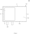
- FIG. 2 is a plan view illustrating a state before the electrode assembly is accommodated in an accommodation step in a method for manufacturing a secondary battery according to a first embodiment of the present invention
- FIG. 3 is a plan view illustrating a state in which the electrode assembly is accommodated in the accommodation step in the method for manufacturing the secondary battery according to the first embodiment of the present invention.
- FIG. 4 is a plan view illustrating a first sealing step in the method for manufacturing the secondary battery according to the first embodiment of the present invention
- FIG. 5 is a plan view illustrating a second sealing step in the method for manufacturing the secondary battery according to the first embodiment of the present invention
- FIG. 6 is a plan view illustrating a second sealing part removing step in the method for the secondary battery according to the first embodiment of the present invention.
- a method for manufacturing a secondary battery comprises an accommodation step (S10) of accommodating an electrode assembly 120 in a battery case 110, a first sealing step (S20) of performing sealing along outer circumferential surfaces a, b, and c of the battery case 110, an electrolyte injection step (S30) of injecting an electrolyte, a second sealing step (S40) of forming a first sealing part 116 and a second sealing part 117, a second sealing part removing step (S50) of removing a portion on which the second sealing part 117 is formed, and a charging step (S60) of applying electricity to the electrode assembly 120.
- the method for manufacturing the secondary battery according to the first embodiment of the present invention may further comprise an aging step in which a predetermined time elapses so that the electrode assembly 120 is impregnated in the electrolyte and a third sealing step of sealing a portion from which a gas pocket part 114 is removed.
- the electrode assembly 120 may be accommodated in the battery case 110 that comprises an accommodation part 113 in which the electrode assembly 120 is accommodated and a gas pocket part 114 connected to the accommodation part 113 to collect a gas generated in the accommodation part 113.
- the battery case 110 may be folded along a virtual line X to cover the accommodation part 113.
- the battery case 110 may comprise an upper case 111 and a lower case 112.
- the battery case 110 may be made of a flexible material.
- the electrode assembly 120 may be a chargeable and dischargeable power generation element and have a shape in which an electrode and a separator are alternately stacked to be combined each other.
- the electrode may comprise a positive electrode and a negative electrode.
- the positive electrode, the separator, and the negative electrode may be alternately disposed.
- the electrode assembly 120 may further comprise an electrode lead 121 connected to an end of the electrode.
- the electrode assembly 120 may be electrically connected to an external device through the electrode lead 121.
- sealing may be performed along the outer circumferential surfaces a, b, and c of the battery case 110, except for an end of the gas pocket part 114. That is, in the first sealing step (S20), the remaining outer circumferential surfaces a, b, and c in three directions, except for the outer circumferential surface d disposed on the end of the gas pocket part 114, among the entire outer circumferential surfaces a, b, c, and d of the battery case 110 in four directions may be sealed to form an initial sealing part 115.
- the electrolyte may be injected into the accommodation part 113 through the end of the gas pocket part 114.
- a liquid injection tube may be inserted into the end of the gas pocket part 114 to inject the electrolyte from the gas pocket part 114 toward the accommodation part 113.
- the end of the gas pocket part 114 may be double-sealed.
- the first sealing part 116 may be formed at a side close to the accommodation part 113
- the second sealing part 117 may be formed at a side that is far from the accommodation part 113.
- the first sealing part 116 may be discontinuously formed so that a non-fused part S12 for degassing and a fused part S11 are formed along a sealing line L.
- the non-fused part S12 for degassing may be gaped to discharge the internal gas to the outside through the non-fused part S12 for degassing.
- the upper case 111 and the lower case 112 may be thermally fused to each other to form the first sealing part 116 and the second sealing part 117.
- the first sealing part 116 may be sealed so that portions of the upper case 111 and the lower case 112, which are disposed at the non-fused part S12 for degassing, are in contact with each other.
- the second sealing step (S40) may be, for example, performed so that a plurality of non-fused parts S12 for degassing are formed.
- the second sealing part 117 may be formed by continuously sealing an edge of the gas pocket part 114 in the battery case 110.
- the end of the gas pocket part 114 may be double-sealed.
- the first sealing part 116 may be partially sealed along the end of the gas pocket part 114, and the second sealing part 117 may be completely sealed.
- the first sealing part 116 may form a discontinuous sealing line to form an unsealed non-fused part, but the second sealing part 117 may form a continuous sealing line to form a continuous sealing line that is completely fused without the non-fused part.
- the portion of the battery case 110, on which the second sealing part 117 is formed may be removed.
- a portion of the battery case 110 may be cut along the virtual line between the first sealing part 116 and the second sealing part 117 to remove the portion on which the second sealing part 117 is formed.
- the charging step (S60) electricity may be applied to the electrode assembly 120 to charge the secondary battery 100.
- the secondary battery 100 may be activated through the charging step (S60).
- a predetermined time may elapse so that the electrode assembly 120 is impregnated in the electrolyte.
- the electrolyte may be filled between the electrode and the separator through the aging step, and thus, the lithium ions may smoothly move.
- FIG. 7 is a plan view illustrating the third sealing step in the method for manufacturing the secondary battery according to the first embodiment of the present invention.
- the gas pocket part 114 may be cut and removed from the battery case 110, and the portion of the battery case 110, from which the gas pocket part 114 is removed, may be sealed to manufacture the secondary battery 100.
- the aging step may be further performed, and then, the third sealing step may be performed.
- the inside of the battery case 110 may be sealed.
- the first sealing part 116 is formed so that the non-fused part S12 for degassing and the fused part S11 may be formed on the gas pocket part 114 of the battery case 110, and when the secondary battery 100 is charged, if the internal pressure increases due to the generated gas, the non-fused part S12 for degassing may be gaped to automatically discharge the internal gas to the outside through the non-fused part S12 for degassing. Therefore, the secondary battery 100 may be prevented from increasing in volume, and the gas may not remain in the electrode to prevent the lithium ions from being precipitated.
- the battery case 110 may be double-sealed so that the first sealing part 116 that is partially sealed and the second sealing part 117 that is completely sealed are formed in the second sealing step (S40). Then, the second sealing part 117 may be removed before the charging step (S60) to prevent an external gas from being introduced into the battery case 110 in the manufacturing process during the charging step (S60) after the electrolyte is injected into the battery case 110 through the electrolyte injection step (S30).
- the sealing may be performed so that the non-fused part S12 for degassing has a width that is gradually narrowed toward the end of the battery case 110.
- FIG. 8 is a plan view illustrating a second sealing step in a method for a secondary battery according to a second embodiment of the present invention.
- a method for manufacturing a secondary battery according to a second embodiment of the present invention is different from the method for manufacturing the secondary battery according to the foregoing first embodiment in that a first sealing part 216 is formed in a different shape in a second sealing step (S40) to manufacture a secondary battery 200.
- a first sealing part 216 is formed in a different shape in a second sealing step (S40) to manufacture a secondary battery 200.
- a first sealing part 216 and a second sealing part 217 are formed in the second sealing step (S40).
- the first sealing part 216 may be discontinuously formed so that a non-fused part S22 for degassing and a fused part S21 are formed along a sealing line.
- the sealing may be performed so that the non-fused part S22 for degassing has a width that is gradually narrowed toward an end of a battery case 210.
- the first sealing part 216 may be formed so that one side of both sides of the non-fused part S22 for degassing is formed in a linear shape, and the other side is formed in a diagonal shape.
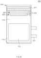
- FIG. 9 is a plan view illustrating a second sealing step in a method for a secondary battery according to a third embodiment of the present invention.
- a method for manufacturing a secondary battery according to the third embodiment of the present invention is different from the method for manufacturing the secondary battery according to the foregoing first and second embodiments in that a first sealing part 316 is formed in a different shape in a second sealing step (S40) to manufacture a secondary battery 300.
- a first sealing part 316 is formed in a different shape in a second sealing step (S40) to manufacture a secondary battery 300.
- a first sealing part 316 and a second sealing part 317 are formed in the second sealing step (S40).
- the first sealing part 316 may be formed so that a non-fused part S32 for degassing and a fused part S31 are formed.
- the first sealing part 316 may be formed so that the non-fused part S32 for degassing is bent in plurality.
- the non-fused part S12 for degassing may be gaped to form a path that is bent in plurality, thereby discharging the internal gas to the outside of the battery case 310 through the non-fused part S32 for degassing.
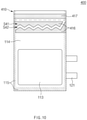
- FIG. 10 is a plan view illustrating a second sealing step in a method for a secondary battery according to a fourth embodiment of the present invention.
- a method for manufacturing a secondary battery according to the fourth embodiment of the present invention is different from the method for manufacturing the secondary battery according to the foregoing first to third embodiments in that a first sealing part 416 is formed in a different shape in a second sealing step (S40) to manufacture a secondary battery 400.
- a first sealing part 416 is formed in a different shape in a second sealing step (S40) to manufacture a secondary battery 400.
- a first sealing part 416 and a second sealing part 417 are formed in the second sealing step (S40).
- the first sealing part 416 may be formed so that a non-fused part S42 for degassing and a fused part S41 are formed.
- the sealing is performed so that the non-fused part S42 for degassing is bent in plurality.
- the non-fused part (S42) for degassing may be bent in a zig-zag shape.
- the non-fused part S42 for degassing may be gaped to form a path that is bent in the zig-zag shape, thereby discharging the internal gas to the outside of the battery case 410 through the non-fused part S42 for degassing.
- FIG. 11 is a plan view illustrating a second sealing step and a temporary sealing step in a method for a secondary battery according to a fifth embodiment of the present invention
- FIG. 12 is a plan view illustrating a second sealing part removing step in the method for the secondary battery according to the fifth embodiment of the present invention
- FIG. 13 is a cross-sectional view taken along line A-A' of FIG. 12 .
- a method for manufacturing the secondary battery according to a fifth embodiment of the present invention is different from the method for manufacturing the secondary battery according to the foregoing first to fourth embodiments of the present invention in that a temporary sealing step is further performed to manufacture a secondary battery 500.
- contents of this embodiment which are duplicated with those according to the foregoing embodiments, will be omitted, and also, differences therebetween will be mainly described.
- a first sealing part 516 and a second sealing part 517 are formed in the second sealing step (S40).
- the first sealing part 516 may be formed so that a non-fused part S52 for degassing and a fused part S51 are formed.
- the sealing is performed so that the non-fused part S52 for degassing is bent in a zig-zag shape.
- an adhesive solution V is placed on an end of the non-fused part S52 for degassing, and an upper case 111 and a lower case 112, which are disposed at the non-fused part S52 for degassing, adhere to each other.
- it may prevent foreign substances or moisture from being introduced into a battery case 510 through the non-fused part S52 for degassing after the second sealing part is removed through a second sealing part removing step (S50).
- the internal pressure reaches a predetermined pressure or more, adhesive force between the upper case 111 and the lower case 112, which are disposed at the non-fused part S52 for degassing, may be released to discharge a gas.
- the temporary sealing step may be, for example, performed after forming the first sealing part 516 in the second sealing step (S40).
- the temporary sealing step may be performed in a state in which the second sealing part 517 is removed after the second sealing part removing step S50.
Landscapes
- Chemical & Material Sciences (AREA)
- Chemical Kinetics & Catalysis (AREA)
- Electrochemistry (AREA)
- General Chemical & Material Sciences (AREA)
- Engineering & Computer Science (AREA)
- Manufacturing & Machinery (AREA)
- Materials Engineering (AREA)
- Secondary Cells (AREA)
- Sealing Battery Cases Or Jackets (AREA)
Abstract
Description
- The present application claims the benefit of the priority of
Korean Patent Application No. 10-2019-0113711, filed on September 16, 2019 - The present invention relates to a method for manufacturing a secondary battery and a secondary battery.
- Secondary batteries are rechargeable unlike primarily batteries, and also, the possibility of compact size and high capacity is high. Thus, recently, many studies on secondary batteries are being carried out. As technology development and demands for mobile devices increase, the demands for secondary batteries as energy sources are rapidly increasing.
- Rechargeable batteries are classified into coin type batteries, cylindrical type batteries, prismatic type batteries, and pouch type batteries according to a shape of a battery case. In such a secondary battery, an electrode assembly mounted in a battery case is a chargeable and dischargeable power generating device having a structure in which an electrode and a separator are stacked.
- The electrode assembly may be approximately classified into a jelly-roll type electrode assembly in which a separator is interposed between a positive electrode and a negative electrode, each of which is provided as the form of a sheet coated with an active material, and then, the positive electrode, the separator, and the negative electrode are wound, a stacked type electrode assembly in which a plurality of positive and negative electrodes with a separator therebetween are sequentially stacked, and a stack/folding type electrode assembly in which stacked type unit cells are wound together with a separation film having a long length.
- Lithium ion secondary batteries are manufactured through processes such as primary charging, aging, and degassing after accommodating an electrode assembly and an electrolyte in a pouch. Here, when a large amount of residual gas exists in the pouch after the primary charging, there has been a problem that difficulties in a transfer process for subsequent processes are caused due to an increase in volume of a cell. Particularly, the gas remaining in an electrode causes precipitation of lithium ions.
- [Prior Art Document] (Patent Document)
Korean Patent Publication No. 10-2014-0015647 - One aspect of the present invention is to provide a method for manufacturing a secondary battery, in which an internal gas generated during charging and activating when the secondary battery is manufactured is capable of being automatically discharged, and a secondary battery.
- A method for manufacturing a secondary battery according to an embodiment of the present invention comprises: an accommodation step of accommodating an electrode assembly in a battery case comprising an accommodation part, in which the electrode assembly is accommodated, and a gas pocket part connected to the accommodation part to collect a gas generated in the accommodation part; a first sealing step of performing sealing along an outer circumferential surface of the battery case except for an end of the gas pocket part; an electrolyte injection step of injecting an electrolyte into the accommodation part through the end of the gas pocket part; a second sealing step of performing double sealing on the end of the gas pocket part so that a first sealing part is formed at a side close to the accommodation part, and a second sealing part is formed at a side that is far from the accommodation part; a second sealing part removing step of removing a portion, on which the second sealing part is formed, from the battery case; and a charging step of applying electricity to the electrode assembly to charge the secondary battery, wherein, in the second sealing step, the first sealing part is discontinuously formed so that a non-fused part for degassing and a fused part are formed along a sealing line, and when an internal pressure increases due to a gas generated through the charging step, the non-fused part for degassing is gaped to discharge the gas to the outside through the non-fused part for degassing.
- The secondary battery according to an embodiment of the present invention may be manufactured through the method for manufacturing the secondary battery according to an embodiment of the present invention.
- According to the present invention, the first sealing part may be formed on the gas pocket part of the battery case to form the non-fused part for degassing and the fused part. As a result, when the secondary battery is charged, the internal pressure may increase due to the generated gas, and thus, the non-fused part for degassing may be gaped to automatically discharge the internal gas to the outside through the non-fused part for degassing. Therefore, the secondary battery may be prevented from increasing in volume, and the gas may not remain in the electrode to prevent the lithium ions from being precipitated.
-
-
FIG. 1 is a flowchart illustrating a method for manufacturing a secondary battery according to an embodiment of the present invention. -
FIG. 2 is a plan view illustrating a state before the electrode assembly is accommodated in an accommodation step in a method for manufacturing a secondary battery according to a first embodiment of the present invention. -
FIG. 3 is a plan view illustrating a state in which the electrode assembly is accommodated in the accommodation step in the method for manufacturing the secondary battery according to the first embodiment of the present invention. -
FIG. 4 is a plan view illustrating a first sealing step in the method for manufacturing the secondary battery according to the first embodiment of the present invention. -
FIG. 5 is a plan view illustrating a second sealing step in the method for manufacturing the secondary battery according to the first embodiment of the present invention. -
FIG. 6 is a plan view illustrating a second sealing part removing step in the method for the secondary battery according to the first embodiment of the present invention. -
FIG. 7 is a plan view illustrating a third sealing step in the method for manufacturing the secondary battery according to the first embodiment of the present invention. -
FIG. 8 is a plan view illustrating a second sealing step in a method for a secondary battery according to a second embodiment of the present invention. -
FIG. 9 is a plan view illustrating a second sealing step in a method for a secondary battery according to a third embodiment of the present invention. -
FIG. 10 is a plan view illustrating a second sealing step in a method for a secondary battery according to a fourth embodiment of the present invention. -
FIG. 11 is a plan view illustrating a second sealing step and a temporary sealing step in a method for a secondary battery according to a fifth embodiment of the present invention. -
FIG. 12 is a plan view illustrating a second sealing part removing step in the method for the secondary battery according to the fifth embodiment of the present invention. -
FIG. 13 is a cross-sectional view taken along line A-A' ofFIG. 12 . - The objectives, specific advantages, and novel features of the present invention will become more apparent from the following detailed description taken in conjunction with the accompanying drawings. It should be noted that the reference numerals are added to the components of the drawings in the present specification with the same numerals as possible, even if they are illustrated in other drawings. Also, the present invention may be embodied in different forms and should not be construed as limited to the embodiments set forth herein. In the following description of the present invention, the detailed descriptions of related arts which may unnecessarily obscure the gist of the present invention will be omitted.
-
FIG. 1 is a flowchart illustrating a method for manufacturing a secondary battery according to an embodiment of the present invention,FIG. 2 is a plan view illustrating a state before the electrode assembly is accommodated in an accommodation step in a method for manufacturing a secondary battery according to a first embodiment of the present invention, andFIG. 3 is a plan view illustrating a state in which the electrode assembly is accommodated in the accommodation step in the method for manufacturing the secondary battery according to the first embodiment of the present invention. - In addition,
FIG. 4 is a plan view illustrating a first sealing step in the method for manufacturing the secondary battery according to the first embodiment of the present invention,FIG. 5 is a plan view illustrating a second sealing step in the method for manufacturing the secondary battery according to the first embodiment of the present invention, andFIG. 6 is a plan view illustrating a second sealing part removing step in the method for the secondary battery according to the first embodiment of the present invention. - Referring to
FIGS. 1 to 6 , a method for manufacturing a secondary battery according to a first embodiment of the present invention comprises an accommodation step (S10) of accommodating anelectrode assembly 120 in abattery case 110, a first sealing step (S20) of performing sealing along outer circumferential surfaces a, b, and c of thebattery case 110, an electrolyte injection step (S30) of injecting an electrolyte, a second sealing step (S40) of forming a first sealingpart 116 and a second sealingpart 117, a second sealing part removing step (S50) of removing a portion on which the second sealingpart 117 is formed, and a charging step (S60) of applying electricity to theelectrode assembly 120. - In addition, the method for manufacturing the secondary battery according to the first embodiment of the present invention may further comprise an aging step in which a predetermined time elapses so that the
electrode assembly 120 is impregnated in the electrolyte and a third sealing step of sealing a portion from which agas pocket part 114 is removed. - In more detail, referring to
FIGS. 1 to 3 , in the accommodation step (S10), theelectrode assembly 120 may be accommodated in thebattery case 110 that comprises anaccommodation part 113 in which theelectrode assembly 120 is accommodated and agas pocket part 114 connected to theaccommodation part 113 to collect a gas generated in theaccommodation part 113. - Here, in the accommodation step (S10), after the
electrode assembly 120 is accommodated in theaccommodation part 113 formed in thebattery case 110 having a sheet shape, thebattery case 110 may be folded along a virtual line X to cover theaccommodation part 113. - Here, the
battery case 110 may comprise anupper case 111 and alower case 112. - Also, the
battery case 110 may be made of a flexible material. - The
electrode assembly 120 may be a chargeable and dischargeable power generation element and have a shape in which an electrode and a separator are alternately stacked to be combined each other. - The electrode may comprise a positive electrode and a negative electrode. The positive electrode, the separator, and the negative electrode may be alternately disposed.
- Also, the
electrode assembly 120 may further comprise anelectrode lead 121 connected to an end of the electrode. Here, theelectrode assembly 120 may be electrically connected to an external device through theelectrode lead 121. - Referring to
FIGS. 1 and4 , in the first sealing step (S20), sealing may be performed along the outer circumferential surfaces a, b, and c of thebattery case 110, except for an end of thegas pocket part 114. That is, in the first sealing step (S20), the remaining outer circumferential surfaces a, b, and c in three directions, except for the outer circumferential surface d disposed on the end of thegas pocket part 114, among the entire outer circumferential surfaces a, b, c, and d of thebattery case 110 in four directions may be sealed to form aninitial sealing part 115. - In the electrolyte injection step (S30), the electrolyte may be injected into the
accommodation part 113 through the end of thegas pocket part 114. Here, in the electrolyte injection step (S30), for example, a liquid injection tube may be inserted into the end of thegas pocket part 114 to inject the electrolyte from thegas pocket part 114 toward theaccommodation part 113. - Referring to
FIGS. 1 and5 , in the second sealing step (S40), the end of thegas pocket part 114 may be double-sealed. Here, the first sealingpart 116 may be formed at a side close to theaccommodation part 113, and the second sealingpart 117 may be formed at a side that is far from theaccommodation part 113. - Also, in the second sealing step (S40), the first sealing
part 116 may be discontinuously formed so that a non-fused part S12 for degassing and a fused part S11 are formed along a sealing line L. As a result, when an internal pressure increases due to the gas generated through the subsequent charging step (S60), the non-fused part S12 for degassing may be gaped to discharge the internal gas to the outside through the non-fused part S12 for degassing. - Also, in the second sealing step (S40), the
upper case 111 and thelower case 112 may be thermally fused to each other to form the first sealingpart 116 and thesecond sealing part 117. Here, the first sealingpart 116 may be sealed so that portions of theupper case 111 and thelower case 112, which are disposed at the non-fused part S12 for degassing, are in contact with each other. - Furthermore, the second sealing step (S40) may be, for example, performed so that a plurality of non-fused parts S12 for degassing are formed.
- Also, in the second sealing step (S40), the
second sealing part 117 may be formed by continuously sealing an edge of thegas pocket part 114 in thebattery case 110. - That is, in the second sealing step (S40), the end of the
gas pocket part 114 may be double-sealed. Here, thefirst sealing part 116 may be partially sealed along the end of thegas pocket part 114, and thesecond sealing part 117 may be completely sealed. Here, thefirst sealing part 116 may form a discontinuous sealing line to form an unsealed non-fused part, but thesecond sealing part 117 may form a continuous sealing line to form a continuous sealing line that is completely fused without the non-fused part. - Referring to
FIGS. 1 ,5 and6 , in the second sealing part removing step (S50), the portion of thebattery case 110, on which thesecond sealing part 117 is formed, may be removed. - Here, in the second sealing part removing step (S50), a portion of the
battery case 110 may be cut along the virtual line between thefirst sealing part 116 and thesecond sealing part 117 to remove the portion on which thesecond sealing part 117 is formed. - In the charging step (S60), electricity may be applied to the
electrode assembly 120 to charge thesecondary battery 100. Here, thesecondary battery 100 may be activated through the charging step (S60). - In the aging step, after performing the charging step S60, a predetermined time may elapse so that the
electrode assembly 120 is impregnated in the electrolyte. Here, the electrolyte may be filled between the electrode and the separator through the aging step, and thus, the lithium ions may smoothly move. -
FIG. 7 is a plan view illustrating the third sealing step in the method for manufacturing the secondary battery according to the first embodiment of the present invention. - Referring to
FIGS. 1 and7 , in the third sealing step, after performing the charging step (S60), thegas pocket part 114 may be cut and removed from thebattery case 110, and the portion of thebattery case 110, from which thegas pocket part 114 is removed, may be sealed to manufacture thesecondary battery 100. Here, for example, after the charging step (S60), the aging step may be further performed, and then, the third sealing step may be performed. - Here, when a sealed sealing
part 118 is formed on the portion of thebattery case 110, from which thegas pocket part 114 is removed, through the third sealing step, the inside of thebattery case 110 may be sealed. - Referring to
FIGS. 1 ,5 , and6 , in the method for manufacturing the secondary battery, which comprises the above-described constituents, according to the first embodiment of the present invention, in the second sealing step (S40), thefirst sealing part 116 is formed so that the non-fused part S12 for degassing and the fused part S11 may be formed on thegas pocket part 114 of thebattery case 110, and when thesecondary battery 100 is charged, if the internal pressure increases due to the generated gas, the non-fused part S12 for degassing may be gaped to automatically discharge the internal gas to the outside through the non-fused part S12 for degassing. Therefore, thesecondary battery 100 may be prevented from increasing in volume, and the gas may not remain in the electrode to prevent the lithium ions from being precipitated. - Also, the
battery case 110 may be double-sealed so that thefirst sealing part 116 that is partially sealed and thesecond sealing part 117 that is completely sealed are formed in the second sealing step (S40). Then, thesecond sealing part 117 may be removed before the charging step (S60) to prevent an external gas from being introduced into thebattery case 110 in the manufacturing process during the charging step (S60) after the electrolyte is injected into thebattery case 110 through the electrolyte injection step (S30). - Referring to
FIGS. 1 and5 , in the method for manufacturing the secondary battery according to the first embodiment of the present invention, for example, in the second sealing step (S40), for example, the sealing may be performed so that the non-fused part S12 for degassing has a width that is gradually narrowed toward the end of thebattery case 110. -
FIG. 8 is a plan view illustrating a second sealing step in a method for a secondary battery according to a second embodiment of the present invention. - Referring to
FIGS. 1 and8 , a method for manufacturing a secondary battery according to a second embodiment of the present invention is different from the method for manufacturing the secondary battery according to the foregoing first embodiment in that afirst sealing part 216 is formed in a different shape in a second sealing step (S40) to manufacture asecondary battery 200. Thus, contents of this embodiment, which are duplicated with those according to the first embodiment, will be omitted, and also, differences therebetween will be mainly described. - In the method for manufacturing the secondary battery according to the second embodiment of the present invention, in the second sealing step (S40), a
first sealing part 216 and asecond sealing part 217 are formed. Here, thefirst sealing part 216 may be discontinuously formed so that a non-fused part S22 for degassing and a fused part S21 are formed along a sealing line. Here, in the second sealing step (S40), for example, the sealing may be performed so that the non-fused part S22 for degassing has a width that is gradually narrowed toward an end of abattery case 210. - Here, in the second sealing step (S40), the
first sealing part 216 may be formed so that one side of both sides of the non-fused part S22 for degassing is formed in a linear shape, and the other side is formed in a diagonal shape. -
FIG. 9 is a plan view illustrating a second sealing step in a method for a secondary battery according to a third embodiment of the present invention. - Referring to
FIGS. 1 and9 , a method for manufacturing a secondary battery according to the third embodiment of the present invention is different from the method for manufacturing the secondary battery according to the foregoing first and second embodiments in that afirst sealing part 316 is formed in a different shape in a second sealing step (S40) to manufacture asecondary battery 300. Thus, contents of this embodiment, which are duplicated with those according to the foregoing embodiments, will be omitted, and also, differences therebetween will be mainly described. - In the method for manufacturing the secondary battery according to the third embodiment of the present invention, in the second sealing step (S40), a
first sealing part 316 and asecond sealing part 317 are formed. Here, thefirst sealing part 316 may be formed so that a non-fused part S32 for degassing and a fused part S31 are formed. Here, in the second sealing step (S40), for example, thefirst sealing part 316 may be formed so that the non-fused part S32 for degassing is bent in plurality. As a result, when an internal pressure increases due to a gas generated through a subsequent charging step (S60), the non-fused part S12 for degassing may be gaped to form a path that is bent in plurality, thereby discharging the internal gas to the outside of thebattery case 310 through the non-fused part S32 for degassing. -
FIG. 10 is a plan view illustrating a second sealing step in a method for a secondary battery according to a fourth embodiment of the present invention. - Referring to
FIGS. 1 and10 , a method for manufacturing a secondary battery according to the fourth embodiment of the present invention is different from the method for manufacturing the secondary battery according to the foregoing first to third embodiments in that afirst sealing part 416 is formed in a different shape in a second sealing step (S40) to manufacture asecondary battery 400. Thus, contents of this embodiment, which are duplicated with those according to the foregoing embodiments, will be omitted, and also, differences therebetween will be mainly described. - In the method for manufacturing the secondary battery according to the fourth embodiment of the present invention, in the second sealing step (S40), a
first sealing part 416 and asecond sealing part 417 are formed. Here, thefirst sealing part 416 may be formed so that a non-fused part S42 for degassing and a fused part S41 are formed. Here, in the second sealing step (S40), for example, the sealing is performed so that the non-fused part S42 for degassing is bent in plurality. - Here, in the second sealing step (S40), the non-fused part (S42) for degassing may be bent in a zig-zag shape.
- As a result, when an internal pressure increases due to a gas generated through a subsequent charging step (S60), the non-fused part S42 for degassing may be gaped to form a path that is bent in the zig-zag shape, thereby discharging the internal gas to the outside of the
battery case 410 through the non-fused part S42 for degassing. -
FIG. 11 is a plan view illustrating a second sealing step and a temporary sealing step in a method for a secondary battery according to a fifth embodiment of the present invention,FIG. 12 is a plan view illustrating a second sealing part removing step in the method for the secondary battery according to the fifth embodiment of the present invention, andFIG. 13 is a cross-sectional view taken along line A-A' ofFIG. 12 . - Referring to
FIGS. 1 and11 , a method for manufacturing the secondary battery according to a fifth embodiment of the present invention is different from the method for manufacturing the secondary battery according to the foregoing first to fourth embodiments of the present invention in that a temporary sealing step is further performed to manufacture asecondary battery 500. Thus, contents of this embodiment, which are duplicated with those according to the foregoing embodiments, will be omitted, and also, differences therebetween will be mainly described. - Referring to
FIGS. 1 and11 to 13 , in the method for manufacturing the secondary battery according to the fifth embodiment of the present invention, in the second sealing step (S40), afirst sealing part 516 and asecond sealing part 517 are formed. Here, thefirst sealing part 516 may be formed so that a non-fused part S52 for degassing and a fused part S51 are formed. Here, in the second sealing step (S40), for example, the sealing is performed so that the non-fused part S52 for degassing is bent in a zig-zag shape. - In the temporary sealing step, an adhesive solution V is placed on an end of the non-fused part S52 for degassing, and an
upper case 111 and alower case 112, which are disposed at the non-fused part S52 for degassing, adhere to each other. Thus, it may prevent foreign substances or moisture from being introduced into abattery case 510 through the non-fused part S52 for degassing after the second sealing part is removed through a second sealing part removing step (S50). Here, when the internal pressure reaches a predetermined pressure or more, adhesive force between theupper case 111 and thelower case 112, which are disposed at the non-fused part S52 for degassing, may be released to discharge a gas. - The temporary sealing step may be, for example, performed after forming the
first sealing part 516 in the second sealing step (S40). - Also, for another example, the temporary sealing step may be performed in a state in which the
second sealing part 517 is removed after the second sealing part removing step S50. - While the present invention has been particularly shown and described with reference to exemplary embodiments thereof, it is to be understood that the scope of the present invention is not limited to the method for manufacturing the secondary battery according to the present invention. It will be understood by those of ordinary skill in the art that various changes in form and details may be made therein without departing from the spirit and scope of the present invention.
- Furthermore, the scope of protection of the present invention will be clarified by the appended claims.
- [Description of the Symbols]
- 100, 200, 300, 400, 500: Secondary battery
- 110, 210, 310, 410, 510: Battery case
- 111: Upper case
- 112: Lower case
- 113: Accommodation part
- 114: Gas pocket part
- 115: Initial sealing part
- 116, 216, 316, 416, 516: First sealing part
- 117, 217, 317, 417, 517: Second sealing part
- 118: Sealed sealing part
- 120: Electrode assembly
- 121: Electrode lead
- a, b, c, d: Outer circumferential surface
- S11, S21, S31, S41, S51: Fused part
- S12, S22, S32, S42, S52: Non-fused part
- V: Adhesive solution
Claims (14)
- A method for manufacturing a secondary battery, the method comprising:an accommodation step of accommodating an electrode assembly in a battery case comprising an accommodation part, in which the electrode assembly is accommodated, and a gas pocket part connected to the accommodation part to collect a gas generated in the accommodation part;a first sealing step of performing sealing along an outer circumferential surface of the battery case except for an end of the gas pocket part;an electrolyte injection step of injecting an electrolyte into the accommodation part through the end of the gas pocket part;a second sealing step of performing double sealing on the end of the gas pocket part so that a first sealing part is formed at a side close to the accommodation part, and a second sealing part is formed at a side that is far from the accommodation part;a second sealing part removing step of removing a portion, on which the second sealing part is formed, from the battery case; anda charging step of applying electricity to the electrode assembly to charge the secondary battery,wherein, in the second sealing step, the first sealing part is discontinuously formed so that a non-fused part for degassing and a fused part are formed along a sealing line, and when an internal pressure increases due to a gas generated through the charging step, the non-fused part for degassing is gaped to discharge the gas to an outside through the non-fused part for degassing.
- The method of claim 1, further comprising, after the charging step is performed, an aging step in which a predetermined time elapses so that the electrode assembly is impregnated in the electrolyte.
- The method of claim 1, wherein the battery case comprises an upper case and a lower case, andin the second sealing step, the upper case and the lower case are thermally fused to each other to form the first sealing part and the second sealing part,wherein the first sealing part is sealed so that portions of the upper case and the lower case, which are disposed at the non-fused part for degassing, are in contact with each other.
- The method of claim 3, wherein, in the second sealing step, the sealing is performed so that the non-fused part for degassing is formed in plurality.
- The method of claim 3, wherein, in the second sealing step, the first sealing part is formed so that the non-fused part for degassing has a width that is gradually narrowed toward an end of a battery case.
- The method of claim 5, wherein, in the second sealing step, the first sealing part is formed so that one side of both sides of the non-fused part for degassing is formed in a linear shape, and the other side is formed in a diagonal shape.
- The method of claim 3, wherein, in the second sealing step, the first sealing part is formed so that the non-fused part for degassing is bent in plurality.
- The method of claim 7, wherein, in the second sealing step, the first sealing part is formed so that the non-fused part for degassing is bent in a zig-zag shape.
- The method of claim 3, further comprising a temporary sealing step in which an adhesive solution is placed on an end of the non-fused part for degassing, and the upper case and the lower case, which are disposed at the non-fused part for degassing, adhere to each other,
wherein when the internal pressure reaches a predetermined pressure or more, adhesive force between the upper case and the lower case, which are disposed at the non-fused part for degassing, is released to discharge the gas. - The method of claim 9, wherein the temporary sealing step is performed after the first sealing part is formed in the second sealing step.
- The method of claim 9, wherein the temporary sealing step is performed in a state in which the second sealing part is removed after the second sealing part removing step.
- The method of claim 1, further comprising, after the charging step is performed, a third sealing step of cutting and removing the gas pocket part from the battery case, and sealing the portion of the battery case, from which the gas pocket part is removed.
- The method of claim 1, wherein the battery case is made of a flexible material.
- A secondary battery manufactured through the method of any one of claims 1 to 13.
Applications Claiming Priority (2)
| Application Number | Priority Date | Filing Date | Title |
|---|---|---|---|
| KR1020190113711A KR102884503B1 (en) | 2019-09-16 | 2019-09-16 | Rechargeable battery manufacturing method, rechargeable battery manufactured from thereof |
| PCT/KR2020/010210 WO2021054603A1 (en) | 2019-09-16 | 2020-08-03 | Method for manufacturing secondary battery, and secondary battery |
Publications (2)
| Publication Number | Publication Date |
|---|---|
| EP3944386A1 true EP3944386A1 (en) | 2022-01-26 |
| EP3944386A4 EP3944386A4 (en) | 2022-06-15 |
Family
ID=74883023
Family Applications (1)
| Application Number | Title | Priority Date | Filing Date |
|---|---|---|---|
| EP20865190.1A Pending EP3944386A4 (en) | 2019-09-16 | 2020-08-03 | SECONDARY BATTERY PRODUCTION METHOD AND SECONDARY BATTERY |
Country Status (5)
| Country | Link |
|---|---|
| US (1) | US11876185B2 (en) |
| EP (1) | EP3944386A4 (en) |
| KR (1) | KR102884503B1 (en) |
| CN (1) | CN113767515B (en) |
| WO (1) | WO2021054603A1 (en) |
Cited By (2)
| Publication number | Priority date | Publication date | Assignee | Title |
|---|---|---|---|---|
| WO2023285275A1 (en) * | 2021-07-12 | 2023-01-19 | Körber Technologies Gmbh | Process for manufacturing a composite element, and corresponding intermediate product and machine |
| EP4411910A4 (en) * | 2022-07-14 | 2025-11-12 | Lg Energy Solution Ltd | METHOD FOR MANUFACTURING A SECONDARY BATTERY, GAS DISCHARGE AND ELECTROLYTE INJECTION MECHANISM AND SECONDARY BATTERY WITH WHICH |
Families Citing this family (4)
| Publication number | Priority date | Publication date | Assignee | Title |
|---|---|---|---|---|
| US20230088026A1 (en) * | 2021-09-17 | 2023-03-23 | GM Global Technology Operations LLC | System for detection and termination of thermal runaway in battery cells |
| CN115172952B (en) * | 2022-09-07 | 2022-12-02 | 楚能新能源股份有限公司 | Air bag structure of soft-packaged battery cell and packaging method of soft-packaged battery cell |
| AU2023360872A1 (en) | 2022-10-12 | 2025-03-06 | Lg Energy Solution, Ltd. | Battery module, and battery pack and energy storage system including the same |
| KR20240134589A (en) * | 2023-03-02 | 2024-09-10 | 주식회사 엘지에너지솔루션 | Secondary battery electrolyte impregnation device, secondary battery electrolyte impregnation method, and secondary battery activation method |
Family Cites Families (28)
| Publication number | Priority date | Publication date | Assignee | Title |
|---|---|---|---|---|
| KR20040081521A (en) | 2003-03-13 | 2004-09-22 | 주식회사 엘지화학 | Secondary lithium battery with safety relief valves on battery case and manufacturing method |
| KR101108447B1 (en) * | 2006-08-28 | 2012-02-08 | 주식회사 엘지화학 | Manufacturing method of pouch type secondary battery excellent in sealing property |
| JP2009021067A (en) | 2007-07-11 | 2009-01-29 | Fuji Heavy Ind Ltd | Power storage assembly |
| KR101128664B1 (en) * | 2007-12-14 | 2012-03-23 | 주식회사 엘지화학 | Secondary Battery of Improved Safety |
| JP2010267593A (en) | 2009-05-18 | 2010-11-25 | Fuji Heavy Ind Ltd | Electricity storage device |
| KR101159099B1 (en) * | 2009-12-01 | 2012-06-22 | 주식회사 엘지화학 | Pouch-Type Battery Case Having Gas-Gathering Residue Portion |
| KR101082196B1 (en) | 2009-12-23 | 2011-11-09 | 삼성에스디아이 주식회사 | Secondary Battery and Manufacturing Method thereof |
| CN103975461B (en) * | 2012-02-02 | 2016-12-07 | 株式会社Lg 化学 | Secondary battery with zigzag seal |
| KR101528001B1 (en) | 2012-06-22 | 2015-06-10 | 주식회사 엘지화학 | Electrode assembly, manufacture thereof, and secondary batteries including same |
| JP5958545B2 (en) | 2012-09-14 | 2016-08-02 | 日産自動車株式会社 | Pressure release structure for in-vehicle battery pack |
| KR101927390B1 (en) * | 2012-10-10 | 2018-12-10 | 에스케이이노베이션 주식회사 | Manufacturing method of pouch secondary battery and Pouch secondary battery |
| CN103000960A (en) | 2012-12-27 | 2013-03-27 | 天津力神电池股份有限公司 | Encapsulation method and encapsulation device of soft-package lithium-ion battery |
| JP6202106B2 (en) | 2014-01-24 | 2017-09-27 | 日産自動車株式会社 | Electrical device |
| KR101675012B1 (en) * | 2014-03-31 | 2016-11-10 | 주식회사 엘지화학 | Method for manufacturing the battery cell |
| KR20160080559A (en) | 2014-12-30 | 2016-07-08 | 주식회사 엘지화학 | A pouch type secondary battery with an enhanced sealing part and a method for manufacturing the secondary battery |
| JP6593626B2 (en) * | 2015-06-17 | 2019-10-23 | セイコーインスツル株式会社 | Electrochemical cell |
| KR102006669B1 (en) * | 2015-08-13 | 2019-08-02 | 주식회사 엘지화학 | Battery Case Applying Hot-Melt Resin and Manufacturing Method Battery cell Comprising the Same |
| CN205543089U (en) * | 2016-01-22 | 2016-08-31 | 北京波士顿动力电池有限公司 | Lithium ion battery |
| KR102123078B1 (en) * | 2016-05-24 | 2020-06-15 | 주식회사 엘지화학 | Manufacturin method of rechargeable battery |
| KR102421369B1 (en) * | 2016-11-25 | 2022-07-15 | 주식회사 엘지에너지솔루션 | A method of manufacturing pouch-typed secondary battery and Jig for used therefor |
| KR102069213B1 (en) * | 2017-01-23 | 2020-01-22 | 주식회사 엘지화학 | Method for preparing lithium secondary battery having high-temperature storage properties |
| KR102649923B1 (en) * | 2017-02-13 | 2024-03-20 | 주식회사 엘지에너지솔루션 | Method for manufacturing pouch type secondary battery |
| KR102278994B1 (en) * | 2017-05-24 | 2021-07-20 | 주식회사 엘지에너지솔루션 | Rechargeable battery and the manufacturing method |
| KR102443908B1 (en) * | 2017-10-17 | 2022-09-16 | 주식회사 엘지에너지솔루션 | Method for manufacturing pouch-type secondary battery including pattern sealing step |
| KR102143625B1 (en) | 2017-11-14 | 2020-08-11 | 삼성에스디아이 주식회사 | Pouch type secondary battery having non-sealing portion |
| KR102164254B1 (en) * | 2017-11-15 | 2020-10-12 | 주식회사 엘지화학 | The Secondary Battery And The Method For Manufacturing Thereof, The Pouch For Secondary Battery And The Method For Manufacturing Thereof |
| KR102320016B1 (en) | 2017-12-15 | 2021-11-02 | 주식회사 엘지에너지솔루션 | Manufacturin method of rechargeable battery |
| KR20190074591A (en) * | 2017-12-20 | 2019-06-28 | 주식회사 엘지화학 | Manufacturin method and manufacturin device of rechargeable battery |
-
2019
- 2019-09-16 KR KR1020190113711A patent/KR102884503B1/en active Active
-
2020
- 2020-08-03 CN CN202080029906.XA patent/CN113767515B/en active Active
- 2020-08-03 EP EP20865190.1A patent/EP3944386A4/en active Pending
- 2020-08-03 WO PCT/KR2020/010210 patent/WO2021054603A1/en not_active Ceased
- 2020-08-03 US US17/606,942 patent/US11876185B2/en active Active
Cited By (2)
| Publication number | Priority date | Publication date | Assignee | Title |
|---|---|---|---|---|
| WO2023285275A1 (en) * | 2021-07-12 | 2023-01-19 | Körber Technologies Gmbh | Process for manufacturing a composite element, and corresponding intermediate product and machine |
| EP4411910A4 (en) * | 2022-07-14 | 2025-11-12 | Lg Energy Solution Ltd | METHOD FOR MANUFACTURING A SECONDARY BATTERY, GAS DISCHARGE AND ELECTROLYTE INJECTION MECHANISM AND SECONDARY BATTERY WITH WHICH |
Also Published As
| Publication number | Publication date |
|---|---|
| KR102884503B1 (en) | 2025-11-13 |
| EP3944386A4 (en) | 2022-06-15 |
| CN113767515B (en) | 2024-02-23 |
| US20220238924A1 (en) | 2022-07-28 |
| US11876185B2 (en) | 2024-01-16 |
| KR20210032219A (en) | 2021-03-24 |
| WO2021054603A1 (en) | 2021-03-25 |
| CN113767515A (en) | 2021-12-07 |
Similar Documents
| Publication | Publication Date | Title |
|---|---|---|
| US11876185B2 (en) | Method for manufacturing secondary battery and secondary battery | |
| CN102005596B (en) | Rechargeable secondary battery having improved safety against puncture and collapse | |
| KR101651712B1 (en) | Secondary Battery | |
| KR20100118394A (en) | Pouch-type secondary battery comprising a portion of non-sealing residue | |
| US20130011721A1 (en) | Pouch and pouch type secondary battery | |
| KR20170132565A (en) | Manufacturin method of rechargeable battery | |
| KR20170021102A (en) | Battery Cell | |
| EP4170766A1 (en) | Secondary battery and manufacturing method for same | |
| KR20180008037A (en) | Electrode assembly | |
| KR20190071129A (en) | Electrode assembly and rechargeable battery comprising the same | |
| KR20150030861A (en) | Pouched type case, battery cell and manufacturing method of battery cell | |
| EP3392933A1 (en) | Secondary cell and method for supplementing electrolyte of secondary cell | |
| EP3654412B1 (en) | Secondary battery | |
| KR102236347B1 (en) | Method for Manufacturing Secondary Battery | |
| EP3386019B1 (en) | Secondary battery | |
| KR102753165B1 (en) | Electrode assembly and secondary battery therewith the electrode assembly and battery pack therewith the secondary battery | |
| KR20170103355A (en) | Pouch-typed Secondary Battery Comprising Jelly-Roll Electrode Assembly | |
| EP4174995A1 (en) | Secondary battery manufacturing method and secondary battery | |
| KR20180136751A (en) | Rechargeable battery | |
| US12132163B2 (en) | Method for manufacturing secondary battery and secondary battery | |
| KR101755161B1 (en) | Pouched type case, battery cell and manufacturing method of battery cell | |
| KR100580767B1 (en) | Pouch Type Lithium-ion Polymer Battery | |
| KR100898069B1 (en) | Electrode Assembly of Lithium Ion Battery and Pouch Type Battery Using the Same | |
| KR20180008039A (en) | Electrode assembly | |
| KR20150051142A (en) | Lithium secondary battery without gas removal process |
Legal Events
| Date | Code | Title | Description |
|---|---|---|---|
| STAA | Information on the status of an ep patent application or granted ep patent |
Free format text: STATUS: THE INTERNATIONAL PUBLICATION HAS BEEN MADE |
|
| PUAI | Public reference made under article 153(3) epc to a published international application that has entered the european phase |
Free format text: ORIGINAL CODE: 0009012 |
|
| STAA | Information on the status of an ep patent application or granted ep patent |
Free format text: STATUS: REQUEST FOR EXAMINATION WAS MADE |
|
| 17P | Request for examination filed |
Effective date: 20211018 |
|
| AK | Designated contracting states |
Kind code of ref document: A1 Designated state(s): AL AT BE BG CH CY CZ DE DK EE ES FI FR GB GR HR HU IE IS IT LI LT LU LV MC MK MT NL NO PL PT RO RS SE SI SK SM TR |
|
| RAP3 | Party data changed (applicant data changed or rights of an application transferred) |
Owner name: LG ENERGY SOLUTION, LTD. |
|
| A4 | Supplementary search report drawn up and despatched |
Effective date: 20220512 |
|
| RIC1 | Information provided on ipc code assigned before grant |
Ipc: H01M 50/186 20210101ALI20220506BHEP Ipc: H01M 50/609 20210101ALI20220506BHEP Ipc: H01M 50/367 20210101ALI20220506BHEP Ipc: H01M 50/184 20210101ALI20220506BHEP Ipc: H01M 50/105 20210101ALI20220506BHEP Ipc: H01M 10/0585 20100101ALI20220506BHEP Ipc: H01M 10/0525 20100101ALI20220506BHEP Ipc: H01M 50/342 20210101ALI20220506BHEP Ipc: H01M 50/557 20210101ALI20220506BHEP Ipc: H01M 10/058 20100101ALI20220506BHEP Ipc: H01M 4/04 20060101ALI20220506BHEP Ipc: H01M 10/44 20060101ALI20220506BHEP Ipc: H01M 10/04 20060101AFI20220506BHEP |
|
| DAV | Request for validation of the european patent (deleted) | ||
| DAX | Request for extension of the european patent (deleted) |