EP3944009A1 - Anzeige - Google Patents
Anzeige Download PDFInfo
- Publication number
- EP3944009A1 EP3944009A1 EP20186765.2A EP20186765A EP3944009A1 EP 3944009 A1 EP3944009 A1 EP 3944009A1 EP 20186765 A EP20186765 A EP 20186765A EP 3944009 A1 EP3944009 A1 EP 3944009A1
- Authority
- EP
- European Patent Office
- Prior art keywords
- display
- light
- modulating
- light output
- modifying
- Prior art date
- Legal status (The legal status is an assumption and is not a legal conclusion. Google has not performed a legal analysis and makes no representation as to the accuracy of the status listed.)
- Pending
Links
- 238000000034 method Methods 0.000 claims abstract description 10
- 238000009877 rendering Methods 0.000 claims abstract description 8
- 230000008878 coupling Effects 0.000 claims description 23
- 238000010168 coupling process Methods 0.000 claims description 23
- 238000005859 coupling reaction Methods 0.000 claims description 23
- 238000004590 computer program Methods 0.000 description 5
- 238000010586 diagram Methods 0.000 description 4
- 230000006870 function Effects 0.000 description 3
- 238000010295 mobile communication Methods 0.000 description 3
- 238000009792 diffusion process Methods 0.000 description 2
- 230000007246 mechanism Effects 0.000 description 2
- 238000012986 modification Methods 0.000 description 2
- 230000004048 modification Effects 0.000 description 2
- 238000012545 processing Methods 0.000 description 2
- 238000003491 array Methods 0.000 description 1
- 230000001419 dependent effect Effects 0.000 description 1
- 238000011161 development Methods 0.000 description 1
- 230000018109 developmental process Effects 0.000 description 1
- 230000009977 dual effect Effects 0.000 description 1
- 230000000694 effects Effects 0.000 description 1
- 238000005265 energy consumption Methods 0.000 description 1
- 230000003287 optical effect Effects 0.000 description 1
- 230000008447 perception Effects 0.000 description 1
- 230000004044 response Effects 0.000 description 1
- 230000000007 visual effect Effects 0.000 description 1
Images


Classifications
-
- G—PHYSICS
- G02—OPTICS
- G02B—OPTICAL ELEMENTS, SYSTEMS OR APPARATUS
- G02B5/00—Optical elements other than lenses
- G02B5/02—Diffusing elements; Afocal elements
- G02B5/0273—Diffusing elements; Afocal elements characterized by the use
- G02B5/0278—Diffusing elements; Afocal elements characterized by the use used in transmission
-
- G—PHYSICS
- G09—EDUCATION; CRYPTOGRAPHY; DISPLAY; ADVERTISING; SEALS
- G09G—ARRANGEMENTS OR CIRCUITS FOR CONTROL OF INDICATING DEVICES USING STATIC MEANS TO PRESENT VARIABLE INFORMATION
- G09G3/00—Control arrangements or circuits, of interest only in connection with visual indicators other than cathode-ray tubes
- G09G3/03—Control arrangements or circuits, of interest only in connection with visual indicators other than cathode-ray tubes specially adapted for displays having non-planar surfaces, e.g. curved displays
-
- G—PHYSICS
- G02—OPTICS
- G02B—OPTICAL ELEMENTS, SYSTEMS OR APPARATUS
- G02B5/00—Optical elements other than lenses
- G02B5/02—Diffusing elements; Afocal elements
- G02B5/0205—Diffusing elements; Afocal elements characterised by the diffusing properties
- G02B5/0257—Diffusing elements; Afocal elements characterised by the diffusing properties creating an anisotropic diffusion characteristic, i.e. distributing output differently in two perpendicular axes
-
- G—PHYSICS
- G02—OPTICS
- G02B—OPTICAL ELEMENTS, SYSTEMS OR APPARATUS
- G02B5/00—Optical elements other than lenses
- G02B5/02—Diffusing elements; Afocal elements
- G02B5/0205—Diffusing elements; Afocal elements characterised by the diffusing properties
- G02B5/0263—Diffusing elements; Afocal elements characterised by the diffusing properties with positional variation of the diffusing properties, e.g. gradient or patterned diffuser
-
- G—PHYSICS
- G06—COMPUTING; CALCULATING OR COUNTING
- G06F—ELECTRIC DIGITAL DATA PROCESSING
- G06F1/00—Details not covered by groups G06F3/00 - G06F13/00 and G06F21/00
- G06F1/16—Constructional details or arrangements
- G06F1/1613—Constructional details or arrangements for portable computers
- G06F1/1615—Constructional details or arrangements for portable computers with several enclosures having relative motions, each enclosure supporting at least one I/O or computing function
- G06F1/1616—Constructional details or arrangements for portable computers with several enclosures having relative motions, each enclosure supporting at least one I/O or computing function with folding flat displays, e.g. laptop computers or notebooks having a clamshell configuration, with body parts pivoting to an open position around an axis parallel to the plane they define in closed position
-
- G—PHYSICS
- G06—COMPUTING; CALCULATING OR COUNTING
- G06F—ELECTRIC DIGITAL DATA PROCESSING
- G06F1/00—Details not covered by groups G06F3/00 - G06F13/00 and G06F21/00
- G06F1/16—Constructional details or arrangements
- G06F1/1613—Constructional details or arrangements for portable computers
- G06F1/1633—Constructional details or arrangements of portable computers not specific to the type of enclosures covered by groups G06F1/1615 - G06F1/1626
- G06F1/1637—Details related to the display arrangement, including those related to the mounting of the display in the housing
- G06F1/1647—Details related to the display arrangement, including those related to the mounting of the display in the housing including at least an additional display
-
- G—PHYSICS
- G09—EDUCATION; CRYPTOGRAPHY; DISPLAY; ADVERTISING; SEALS
- G09G—ARRANGEMENTS OR CIRCUITS FOR CONTROL OF INDICATING DEVICES USING STATIC MEANS TO PRESENT VARIABLE INFORMATION
- G09G3/00—Control arrangements or circuits, of interest only in connection with visual indicators other than cathode-ray tubes
- G09G3/04—Control arrangements or circuits, of interest only in connection with visual indicators other than cathode-ray tubes for presentation of a single character by selection from a plurality of characters, or by composing the character by combination of individual elements, e.g. segments using a combination of such display devices for composing words, rows or the like, in a frame with fixed character positions
- G09G3/06—Control arrangements or circuits, of interest only in connection with visual indicators other than cathode-ray tubes for presentation of a single character by selection from a plurality of characters, or by composing the character by combination of individual elements, e.g. segments using a combination of such display devices for composing words, rows or the like, in a frame with fixed character positions using controlled light sources
-
- G—PHYSICS
- G02—OPTICS
- G02F—OPTICAL DEVICES OR ARRANGEMENTS FOR THE CONTROL OF LIGHT BY MODIFICATION OF THE OPTICAL PROPERTIES OF THE MEDIA OF THE ELEMENTS INVOLVED THEREIN; NON-LINEAR OPTICS; FREQUENCY-CHANGING OF LIGHT; OPTICAL LOGIC ELEMENTS; OPTICAL ANALOGUE/DIGITAL CONVERTERS
- G02F1/00—Devices or arrangements for the control of the intensity, colour, phase, polarisation or direction of light arriving from an independent light source, e.g. switching, gating or modulating; Non-linear optics
- G02F1/01—Devices or arrangements for the control of the intensity, colour, phase, polarisation or direction of light arriving from an independent light source, e.g. switching, gating or modulating; Non-linear optics for the control of the intensity, phase, polarisation or colour
- G02F1/13—Devices or arrangements for the control of the intensity, colour, phase, polarisation or direction of light arriving from an independent light source, e.g. switching, gating or modulating; Non-linear optics for the control of the intensity, phase, polarisation or colour based on liquid crystals, e.g. single liquid crystal display cells
- G02F1/133—Constructional arrangements; Operation of liquid crystal cells; Circuit arrangements
- G02F1/1333—Constructional arrangements; Manufacturing methods
- G02F1/13336—Combining plural substrates to produce large-area displays, e.g. tiled displays
-
- G—PHYSICS
- G09—EDUCATION; CRYPTOGRAPHY; DISPLAY; ADVERTISING; SEALS
- G09G—ARRANGEMENTS OR CIRCUITS FOR CONTROL OF INDICATING DEVICES USING STATIC MEANS TO PRESENT VARIABLE INFORMATION
- G09G2310/00—Command of the display device
- G09G2310/02—Addressing, scanning or driving the display screen or processing steps related thereto
-
- G—PHYSICS
- G09—EDUCATION; CRYPTOGRAPHY; DISPLAY; ADVERTISING; SEALS
- G09G—ARRANGEMENTS OR CIRCUITS FOR CONTROL OF INDICATING DEVICES USING STATIC MEANS TO PRESENT VARIABLE INFORMATION
- G09G2320/00—Control of display operating conditions
- G09G2320/06—Adjustment of display parameters
- G09G2320/0626—Adjustment of display parameters for control of overall brightness
-
- H—ELECTRICITY
- H10—SEMICONDUCTOR DEVICES; ELECTRIC SOLID-STATE DEVICES NOT OTHERWISE PROVIDED FOR
- H10K—ORGANIC ELECTRIC SOLID-STATE DEVICES
- H10K59/00—Integrated devices, or assemblies of multiple devices, comprising at least one organic light-emitting element covered by group H10K50/00
- H10K59/10—OLED displays
- H10K59/18—Tiled displays
Definitions
- the present specification relates to displays of devices, such as mobile communication devices.
- this specification describes an apparatus comprising means for performing: modulating or modifying light output by one or more light sources (e.g. a plurality of light sources), wherein the light output is for use in rendering content in a first direction using a display of the apparatus, wherein the display has at least one curved portion, wherein the modulating or modifying of the light output by the one or more light sources modulates or modifies said light within said at least one curved portion such that said content is rendered in the first direction within said curved portion.
- the first direction may be substantially perpendicular to the display.
- At least one of said at least one curved portion is at a periphery of the apparatus.
- the said modulating or modifying of the light output by the light source may be such that said content is rendered in the first direction within the curved periphery of the apparatus.
- the means for modulating or modifying light output by the one or more light sources may be configured to attenuate light in directions other than the first direction.
- the attenuation may be complete (e.g. 100% attenuation) such that the light is removed is the directions others than the first direction. In other embodiments, the removal may be partial.
- the means for modulating or modifying the light output may comprise an absorbing diffuser.
- the means for modulating or modifying the light output may comprise an anisotropic diffusor.
- the apparatus may further comprise means for performing: increasing light intensity of light output within the or each curved portion of the display to compensate for modulating or modifying the light output within the curved portion.
- the apparatus may further comprise means for performing: coupling (e.g. connecting) the display of the apparatus to one or more displays of another apparatus, such as one or more displays of each of a plurality of other apparatus.
- the said means for coupling/connecting may comprise a magnetic coupling means and/or a hinge means.
- the display is a foldable display comprising a first portion and a second portion, such that an angle between the first and second portions is changeable.
- the said means may comprise: at least one processor; and at least one memory including computer program code, the at least one memory and the computer program configured, with the at least one processor, to cause the performance of the apparatus.
- this specification describes a method comprising: modulating or modifying light output by one or more light sources (e.g. a plurality of light sources), wherein the light output is for use in rendering content in a first direction using a display, wherein the display has at least one curved portion, wherein the modulating or modifying of the light output by the one or more light sources modulates or modifies said light within said at least one curved portion such that said content is rendered in the first direction within said curved portion.
- the first direction may be substantially perpendicular to the display.
- At least one of said at least one curved portion may be at a periphery of the display, wherein the modulating or modifying of the light output by the light source is such that said content is rendered in the first direction within the curved periphery of the display.
- modulating or modifying the light output by the one or more light sources comprises attenuating light in directions other than the first direction.
- the attenuation may be complete (e.g. 100% attenuation) such that the light is removed is the directions others than the first direction.
- the method may further comprise increasing light intensity of light output within the or each curved portion of the display to compensate for modulating or modifying the light output within the curved portion.
- the method may further comprise: coupling (e.g. connecting) the display of the apparatus to one or more displays of another apparatus, such as one or more displays of each of a plurality of other apparatus.
- the said means for couling/connecting may comprise a magnetic coupling means and/or a hinge means.
- the display may be a foldable display comprising a first portion and a second portion, such that an angle between the first and second portions is changeable.
- this specification describes computer-readable instructions which, when executed by computing apparatus, cause the computing apparatus to perform (at least) any method as described with reference to the second aspect.
- this specification describes a computer-readable medium (such as a non-transitory computer-readable medium) comprising program instructions stored thereon for performing (at least) any method as described with reference to the second aspect.
- FIG. 1 is a block diagram of a user device 10, in accordance with an example embodiment.
- the user device 10 may, for example, be a mobile communication device, a laptop or some other device having a display.
- the user device 10 comprises a first display 12a and a second display 12b.
- the first display 12a is folded relative to the second display 12b.
- the folding of the first display 12a has the effect of partially closing the overall display of the user device 10.
- a display output (comprising a first face 13 and a second face 14) is provided on the second display 12b only.
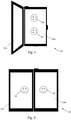
- FIG. 2 is a block diagram of the user device 10 in accordance with an example embodiment.
- the displays of the user device 10 are flat, such that the first and second displays 12a and 12b are operable as a single display.
- the example user device 10 provides a single display output including a first face 23 and a second face 24 that are displayed across the first and second displays 12a and 12b.
- the first and second displays 12a and 12b are separate displays, such that a visual break or line appears between the two screens.
- the user device 10 is not able to provide a seamless, continuous screen with the reliability of having two or more screens and conventional reliable hinge(s) or similar coupling mechanism.
- FIG. 3 is a schematic cross section of a user device, indicated generally by the reference numeral 30, in accordance with an example embodiment.
- the user device 30 may, for example, be a mobile communication device, a laptop or some other device having a display.
- the user device 30 comprise one or more light sources for use in rendering content in a first direction using a display of the user device 30. For most of the area of the display of the user device, content is rendered in a first direction 32 generally perpendicular to the display. As shown in FIG. 3 , the display is curved towards a periphery of the user device 30. Light sources provided within the user device 30 (such as the light source 40 described below) follow the shape of the exterior of the user device; accordingly, the direction of light output by the display is generally in a direction perpendicular to the local exterior surface of the display (e.g. the directions 34 shown in FIG. 3 ).
- FIG. 4 shows a light source, indicated generally by the reference numeral 40, in accordance with an example embodiment.
- the light source 40 outputs light is multiple directions, as indicated by the light outputs 42 (indeed, the light source 40 may be substantially omnidirectional).
- the user device 30 may have a plurality of light sources 40.
- FIG. 5 is a flow chart showing an algorithm, indicated generally by the reference numeral 50, in accordance with an example embodiment.
- the algorithm 50 starts at operation 52 where one or more light sources (such as light sources 40) are provided for use in rendering content in a first direction using a display (such as the display of the user device 30).
- the display may be curved towards a periphery (such as the user device 30) or curved elsewhere.
- the light output in the vicinity of the curved edge is modified or modulated such that content is rendered in the first direction in the vicinity of the curved area (e.g. the curved periphery).
- the light output generally in the directions 34 described above may be modified or modulated to be provided in the direction 32.
- FIG. 6 is a schematic cross section of a user device, indicated generally by the reference numeral 60, in accordance with an example embodiment.
- the light output by the user device has been modified or modulated (as described above in the operation 54 of the algorithm 50) such that light is output in a direction substantially perpendicular to the display.
- content is rendered in a first direction 62 generally perpendicular to the display (similar to the direction 32 of the user device 30 described above).
- content is rendered in directions substantially parallel to the first direction 62, as discussed further below.
- a plurality of light sources are provided, providing a plurality of light beam outputs (as shown in FIG. 6 ).
- the light sources may take many forms. For example, omnidirectional light sources, or light sources having at least many directions of light emittance maybe used (such as the light source 40 described above).
- the operation 54 of the algorithm 50 may be configured to remove or attenuate light in directions other than the first direction 62.
- horizontal components of light at the periphery of the user device maybe removed.
- the operation 54 may be implemented using a diffuser or similar device around the periphery of the device to give the illusion that the display goes right to the edge. In this way, a bevel distortion at the edge of many displays can be removed. As shown in FIG. 6 , the display of the user device 60 wraps around the corner of the device (at the curved sections) and modulating diffusing elements can be used to redirect the light (in the regions 64a and 64b) so that it gives the user the illusion that the display goes right to the edge.
- An input image for display may be geometrically adapted to compensate for any optical distortion problems. This may allow two or more displays to be positioned beside one another without the perception of a break or line between the displays. As a result, dual, triple, or quadruple displays beside each other appear like a single display.
- FIG. 7 shows a light source system, indicated generally by the reference numeral 70, in accordance with an example embodiment.
- the light source system 70 comprises a light source 72 and a diffuser 74.
- the light source 72 may be the same as the light source 40 described above.
- the diffuser 74 may be an absorbing diffuser (in which light in unwanted direction is removed) or an anisotrpic diffuser (e.g. a diffuser having a small output angle).
- FIG. 8 is a flow chart showing an algorithm, indicated generally by the reference numeral 80, in accordance with an example embodiment.
- the algorithm 80 starts with the operation 52 described above, wherein one or more light sources are provided for use in rendering content in a first direction using a display (such as the display of the user device 60).
- the displays may be curved towards a periphery.
- the operation 82 may include increasing light intensity of light output near the curved periphery to compensate for modulating the light output in the vicinity of the curved periphery. (The operation 82 is dotted in FIG. 8 , since that operation may be omitted in some example embodiments.)
- the light output in the vicinity of the curved portion (e.g. a curved edge) is modified or modulated such that content is rendered in the first direction in the vicinity of the curved region.
- light at a curved periphery (or some other curved region) of a user device is unmodulated, such that, for example, the light emits unidirectionally.
- An absorbing diffusor (such as the diffuser 74) can be provided to remove undesired light direction.
- the OLED or any display
- the amount of diffusion would increase along the curved surface so that light goes generally upwards too.
- light will diffuse in all directions so the intensity of the usable light going upward will decrease along the surface. This can be compensated for by modulating the luminance of the display (see the operation 82 described above). This will tend to increase the energy consumption and/or reduce the overall luminance of the display if the luminance of the flat sections is to be kept also in the curved section.
- modulated anisotropic diffusor with a small output angle, an illustration of which is shown in FIG. 7 .
- Both diffusing cone direction and ellipticity can be controlled in order to, for example, diffuse only perpendicularly to the edge of a user device (such as the user device 60).
- This type of diffusor would modulate the light so that emits in the desired direction without the notable drop in intensity that would occur using conventional absorbing modulation as described above.
- the operation 82 may be omitted.
- FIG. 9 is a flow chart showing an algorithm, indicated generally by the reference numeral 90, in accordance with an example embodiment.
- the algorithm 90 starts at operation 92, where two out more displays are coupled together.
- operation 94 an output to be displayed using a combined display of the coupled displayed is determined.
- operation 96 the display determined in operation 94 is provided to the coupled display. In this way, multiple displays that are coupled together (in the operation 92) can be used to a single display.
- Displays may be coupled together in many different ways. A number of example implementations of the operation 92 are discussed below. Of course the skilled person will be aware of other potential coupling configurations that could be provided.
- FIG. 10 is a schematic cross section of a user device, indicated generally by the reference numeral 100, in accordance with an example embodiment.
- the user device 100 comprises a first display 101 and a second display 102, which displays are foldable using a hinge 103.
- the first display 101 has an output indicated generally by the reference numeral 104 and the second display has an output indicated generally by the reference numeral 105.
- the displays 101 and 102 each have curved peripheries, with the light sources as the peripheries being modulated or modified such that the output across the first display 101 is provided in a single direction and the output across the second display 102 is provided in a single direction.
- the first and second displays are orientated in the same direction such that the outputs 104 and 105 can be used to provide a single display.
- FIG. 11 is a bottom view of a user device, indicated generally by the reference numeral 110, in accordance with an example embodiment.
- user device 110 comprise a first display 111 and a second display 112 coupled using a hinge 113.
- the user device 110 is therefore similar to the user device 100, differing only in the hinge position, which results in a different configuration of displays when the user device displays an unfolded.
- the hinges 103 and 113 can be used to provide reliable mechanisms for providing the respective displays as foldable displays. Such displays maybe reliable since they can be provided without being subject to tensile, compressive, or perpendicular stress. Moreover, displays can be provided such that the user can be provided with an unbroken large single screen consisting of displays from multiple user devices and/or multiple displays of the same user device.
- FIG. 12 is a schematic cross section of a system, indicated generally by the reference numeral 120, in accordance with an example embodiment.
- the system 120 comprises a first device 121 and a second device 122 that are coupled together using a magnetic coupling arrangement 123.
- the first device 121 has an output indicated generally by the reference numeral 124 and the second device 122 has an output indicated generally by the reference numeral 125.
- the output provided by the system 120 is similar to the output provided by the user device 100. However, in the system 120, the first and second devices maybe entirely separate devices, perhaps owned by different users.
- the first device has an additional magnetic coupling arrangement 126 that can enable a further device to be magnetically coupled to the first device 121 (thereby extending the display further).
- the second device has a similar additional magnetic coupling 128.
- the display provided by the system 120 can, in principle, be extended to include any number of similar devices.
- Coupling means could be provided on multiple sides of a user devices, such that a display can be extended in two-dimensions.
- coupling means may be combined such that, for example, both magnetic coupling and hinge coupling is provided.
- FIG. 13 is a plan view of a display, indicated generally by the reference numeral 130, in accordance with an example embodiment.
- the display 130 comprises the a first display 132 of a first device, a second display 133 of a second device, a third display 134 of a third device and a fourth display 135 of a fourth device.
- Coupling between the displays 132 to 135 may take many different forms (e.g. using hinges, magnetic couplings or some other coupling arrangement).
- FIG. 14 is a plan view of a display, indicated generally by the reference numeral 140, in accordance with an example embodiment.
- the display 140 comprises: a first display 142 of a first device; a second display 143 of a second device; a third display 144 and a fourth display 145 of a third device; and a fifth display 146 and a sixth display 147 of a fourth device.
- the first display 142 is coupled to the second display 143, the third display 144 and the fourth display 145.
- the second display 143 is coupled to the first display 142, the fifth display 146 and the sixth display 147.
- the third display 144 is coupled to the first display 142 and the fourth display 145.
- the fourth display 145 is coupled to the first display 142, the third display 144 and the fifth display 146.
- the firth display is coupled to the second display 143, the fourth display 145 and the sixth display 147.
- the sixth display 147 is coupled to the second display 143 and the fifth display 146. Coupling between the displays 142 to 147 may take many different forms (e.g. using hinges, magnetic couplings or some other coupling arrangement).
- the systems 130 and 140 enable multiple user devices (e.g. devices of different users) to be coupled together in many configurations to make a single display.
- a large display could be constructed from multiple relatively small user devices displays, for example for providing a video conference display or a display for watching a movie.
- Embodiments of the present invention may be implemented in software, hardware, application logic or a combination of software, hardware and application logic.
- the software, application logic and/or hardware may reside on memory, or any computer media.
- the application logic, software or an instruction set is maintained on any one of various conventional computer-readable media.
- a "memory" or “computer-readable medium” may be any non-transitory media or means that can contain, store, communicate, propagate or transport the instructions for use by or in connection with an instruction execution system, apparatus, or device, such as a computer.
- references to, where relevant, "computer-readable medium”, “computer program product”, “tangibly embodied computer program” etc., or a “processor” or “processing circuitry” etc. should be understood to encompass not only computers having differing architectures such as single/multi-processor architectures and sequencers/parallel architectures, but also specialised circuits such as field programmable gate arrays FPGA, application specify circuits ASIC, signal processing devices/apparatus and other devices/apparatus. References to computer program, instructions, code etc.
- programmable processor firmware such as the programmable content of a hardware device/apparatus as instructions for a processor or configured or configuration settings for a fixed function device/apparatus, gate array, programmable logic device/apparatus, etc.
Landscapes
- Engineering & Computer Science (AREA)
- Physics & Mathematics (AREA)
- Computer Hardware Design (AREA)
- General Physics & Mathematics (AREA)
- Theoretical Computer Science (AREA)
- Human Computer Interaction (AREA)
- General Engineering & Computer Science (AREA)
- Optics & Photonics (AREA)
- Mathematical Physics (AREA)
- Devices For Indicating Variable Information By Combining Individual Elements (AREA)
Priority Applications (3)
| Application Number | Priority Date | Filing Date | Title |
|---|---|---|---|
| EP20186765.2A EP3944009A1 (de) | 2020-07-20 | 2020-07-20 | Anzeige |
| US18/016,007 US11893917B2 (en) | 2020-07-20 | 2021-06-22 | Apparatus and method for modulating light output using a display |
| PCT/EP2021/066966 WO2022017710A1 (en) | 2020-07-20 | 2021-06-22 | Display |
Applications Claiming Priority (1)
| Application Number | Priority Date | Filing Date | Title |
|---|---|---|---|
| EP20186765.2A EP3944009A1 (de) | 2020-07-20 | 2020-07-20 | Anzeige |
Publications (1)
| Publication Number | Publication Date |
|---|---|
| EP3944009A1 true EP3944009A1 (de) | 2022-01-26 |
Family
ID=71728660
Family Applications (1)
| Application Number | Title | Priority Date | Filing Date |
|---|---|---|---|
| EP20186765.2A Pending EP3944009A1 (de) | 2020-07-20 | 2020-07-20 | Anzeige |
Country Status (3)
| Country | Link |
|---|---|
| US (1) | US11893917B2 (de) |
| EP (1) | EP3944009A1 (de) |
| WO (1) | WO2022017710A1 (de) |
Citations (4)
| Publication number | Priority date | Publication date | Assignee | Title |
|---|---|---|---|---|
| US20160363291A1 (en) * | 2015-01-06 | 2016-12-15 | Boe Technology Group Co., Ltd. | Optical path adjusting unit and display device |
| US20170269742A1 (en) * | 2016-03-15 | 2017-09-21 | Microsoft Technology Licensing, Llc | Display window with light steering |
| EP3343274A2 (de) * | 2016-12-30 | 2018-07-04 | LG Display Co., Ltd. | Anzeigevorrichtung, mehrfachbildschirmanzeigevorrichtung damit und verfahren zur herstellung davon |
| US20180239574A1 (en) * | 2017-02-21 | 2018-08-23 | Jeffrey E. Koziol | Detachable Display System |
Family Cites Families (3)
| Publication number | Priority date | Publication date | Assignee | Title |
|---|---|---|---|---|
| US20100253685A1 (en) * | 2009-04-01 | 2010-10-07 | Lightmap Limited | Generating Data for Use in Image Based Lighting Rendering |
| US10726574B2 (en) * | 2017-04-11 | 2020-07-28 | Dolby Laboratories Licensing Corporation | Passive multi-wearable-devices tracking |
| CN113544560A (zh) * | 2018-12-28 | 2021-10-22 | 奇跃公司 | 具有发光微显示器的虚拟和增强现实显示系统 |
-
2020
- 2020-07-20 EP EP20186765.2A patent/EP3944009A1/de active Pending
-
2021
- 2021-06-22 WO PCT/EP2021/066966 patent/WO2022017710A1/en active Application Filing
- 2021-06-22 US US18/016,007 patent/US11893917B2/en active Active
Patent Citations (4)
| Publication number | Priority date | Publication date | Assignee | Title |
|---|---|---|---|---|
| US20160363291A1 (en) * | 2015-01-06 | 2016-12-15 | Boe Technology Group Co., Ltd. | Optical path adjusting unit and display device |
| US20170269742A1 (en) * | 2016-03-15 | 2017-09-21 | Microsoft Technology Licensing, Llc | Display window with light steering |
| EP3343274A2 (de) * | 2016-12-30 | 2018-07-04 | LG Display Co., Ltd. | Anzeigevorrichtung, mehrfachbildschirmanzeigevorrichtung damit und verfahren zur herstellung davon |
| US20180239574A1 (en) * | 2017-02-21 | 2018-08-23 | Jeffrey E. Koziol | Detachable Display System |
Also Published As
| Publication number | Publication date |
|---|---|
| US20230186808A1 (en) | 2023-06-15 |
| US11893917B2 (en) | 2024-02-06 |
| WO2022017710A1 (en) | 2022-01-27 |
Similar Documents
| Publication | Publication Date | Title |
|---|---|---|
| US6906860B2 (en) | Curved-screen immersive rear projection display | |
| US6866388B2 (en) | Projection device | |
| US20110215990A1 (en) | Apparatus for Obscuring Non-Displaying Areas of Display Panels | |
| US8115698B2 (en) | Methods and systems for image processing and display | |
| JP5996602B2 (ja) | 投影システム及びその投影方法 | |
| KR102393526B1 (ko) | 곡면 표시 장치 | |
| US9921362B2 (en) | Backlight source and display apparatus comprising the same | |
| US8094131B2 (en) | Touch control virtual screen apparatus | |
| US20090059173A1 (en) | Methods and systems for projecting images | |
| TW201513074A (zh) | 顯示裝置、拼接式顯示器及顯示面板 | |
| JP2009520334A5 (de) | ||
| KR102538309B1 (ko) | 양방향 디스플레이 장치 및 방법 | |
| US10564346B2 (en) | Backlight module and display device | |
| TW201432331A (zh) | 影像補償裝置、顯示裝置及拼接型顯示裝置 | |
| EP3944009A1 (de) | Anzeige | |
| US10296279B2 (en) | Displaying images across multiple displays | |
| US20200292931A1 (en) | Customized reflection profiles for retro-reflective display system optimization | |
| US20190121150A1 (en) | Methods for system layout optimization for retro-reflective based display systems | |
| JP2015081965A (ja) | 画像表示装置及び非平面型スクリーン | |
| US11677915B2 (en) | Image display device | |
| JP2018026775A (ja) | 映像提示システム | |
| JP2016009129A (ja) | 画像表示装置 | |
| US20230204949A1 (en) | Color-selective effective focal length optics | |
| US20220128891A1 (en) | System and method of actively reducing an appearance of a seam in a mirror array | |
| US20230315374A1 (en) | Distraction filtering mode for displays |
Legal Events
| Date | Code | Title | Description |
|---|---|---|---|
| PUAI | Public reference made under article 153(3) epc to a published international application that has entered the european phase |
Free format text: ORIGINAL CODE: 0009012 |
|
| STAA | Information on the status of an ep patent application or granted ep patent |
Free format text: STATUS: THE APPLICATION HAS BEEN PUBLISHED |
|
| AK | Designated contracting states |
Kind code of ref document: A1 Designated state(s): AL AT BE BG CH CY CZ DE DK EE ES FI FR GB GR HR HU IE IS IT LI LT LU LV MC MK MT NL NO PL PT RO RS SE SI SK SM TR |
|
| STAA | Information on the status of an ep patent application or granted ep patent |
Free format text: STATUS: REQUEST FOR EXAMINATION WAS MADE |
|
| 17P | Request for examination filed |
Effective date: 20220722 |
|
| RBV | Designated contracting states (corrected) |
Designated state(s): AL AT BE BG CH CY CZ DE DK EE ES FI FR GB GR HR HU IE IS IT LI LT LU LV MC MK MT NL NO PL PT RO RS SE SI SK SM TR |
|
| STAA | Information on the status of an ep patent application or granted ep patent |
Free format text: STATUS: EXAMINATION IS IN PROGRESS |
|
| 17Q | First examination report despatched |
Effective date: 20230713 |