EP3943921A1 - Inspection device, inspection method, and non-transitory computer-readable medium - Google Patents
Inspection device, inspection method, and non-transitory computer-readable medium Download PDFInfo
- Publication number
- EP3943921A1 EP3943921A1 EP19920093.2A EP19920093A EP3943921A1 EP 3943921 A1 EP3943921 A1 EP 3943921A1 EP 19920093 A EP19920093 A EP 19920093A EP 3943921 A1 EP3943921 A1 EP 3943921A1
- Authority
- EP
- European Patent Office
- Prior art keywords
- inspected
- product
- powder
- vibration
- inspection apparatus
- Prior art date
- Legal status (The legal status is an assumption and is not a legal conclusion. Google has not performed a legal analysis and makes no representation as to the accuracy of the status listed.)
- Granted
Links
Images


Classifications
-
- G—PHYSICS
- G01—MEASURING; TESTING
- G01N—INVESTIGATING OR ANALYSING MATERIALS BY DETERMINING THEIR CHEMICAL OR PHYSICAL PROPERTIES
- G01N21/00—Investigating or analysing materials by the use of optical means, i.e. using sub-millimetre waves, infrared, visible or ultraviolet light
- G01N21/84—Systems specially adapted for particular applications
- G01N21/88—Investigating the presence of flaws or contamination
- G01N21/90—Investigating the presence of flaws or contamination in a container or its contents
- G01N21/9018—Dirt detection in containers
- G01N21/9027—Dirt detection in containers in containers after filling
-
- G—PHYSICS
- G06—COMPUTING OR CALCULATING; COUNTING
- G06T—IMAGE DATA PROCESSING OR GENERATION, IN GENERAL
- G06T7/00—Image analysis
- G06T7/0002—Inspection of images, e.g. flaw detection
- G06T7/0004—Industrial image inspection
- G06T7/001—Industrial image inspection using an image reference approach
-
- B—PERFORMING OPERATIONS; TRANSPORTING
- B06—GENERATING OR TRANSMITTING MECHANICAL VIBRATIONS IN GENERAL
- B06B—METHODS OR APPARATUS FOR GENERATING OR TRANSMITTING MECHANICAL VIBRATIONS OF INFRASONIC, SONIC, OR ULTRASONIC FREQUENCY, e.g. FOR PERFORMING MECHANICAL WORK IN GENERAL
- B06B1/00—Methods or apparatus for generating mechanical vibrations of infrasonic, sonic, or ultrasonic frequency
- B06B1/02—Methods or apparatus for generating mechanical vibrations of infrasonic, sonic, or ultrasonic frequency making use of electrical energy
- B06B1/0207—Driving circuits
-
- G—PHYSICS
- G01—MEASURING; TESTING
- G01N—INVESTIGATING OR ANALYSING MATERIALS BY DETERMINING THEIR CHEMICAL OR PHYSICAL PROPERTIES
- G01N21/00—Investigating or analysing materials by the use of optical means, i.e. using sub-millimetre waves, infrared, visible or ultraviolet light
- G01N21/84—Systems specially adapted for particular applications
- G01N21/88—Investigating the presence of flaws or contamination
- G01N21/94—Investigating contamination, e.g. dust
-
- G—PHYSICS
- G06—COMPUTING OR CALCULATING; COUNTING
- G06V—IMAGE OR VIDEO RECOGNITION OR UNDERSTANDING
- G06V10/00—Arrangements for image or video recognition or understanding
- G06V10/70—Arrangements for image or video recognition or understanding using pattern recognition or machine learning
- G06V10/74—Image or video pattern matching; Proximity measures in feature spaces
- G06V10/75—Organisation of the matching processes, e.g. simultaneous or sequential comparisons of image or video features; Coarse-fine approaches, e.g. multi-scale approaches; using context analysis; Selection of dictionaries
- G06V10/751—Comparing pixel values or logical combinations thereof, or feature values having positional relevance, e.g. template matching
-
- H—ELECTRICITY
- H04—ELECTRIC COMMUNICATION TECHNIQUE
- H04N—PICTORIAL COMMUNICATION, e.g. TELEVISION
- H04N23/00—Cameras or camera modules comprising electronic image sensors; Control thereof
- H04N23/70—Circuitry for compensating brightness variation in the scene
- H04N23/74—Circuitry for compensating brightness variation in the scene by influencing the scene brightness using illuminating means
Definitions
- the present disclosure relates to a product-inspection apparatus, a product-inspection method, and a non-transitory computer readable medium.
- An ordinary product-inspection apparatus is configured to determine whether or not an object to be inspected, which is an object in which an object to be contained is contained in a container, is a quality product by determining whether or not a foreign substance is contained in the object to be inspected.
- a product-inspection apparatus disclosed in Patent Literature 1 is configured to, while applying vertical and horizontal vibrations to an object to be inspected, which is an object in which a powder is contained in a transparent container, and thereby making the powder circulate and flow therein, take an image of the circulating and flowing powder through a wall surface of the transparent container in which the powder is in contact with the inner surface thereof, and thereby to determine whether or not a foreign substance is contained in the object to be inspected based on the taken image information.
- Patent Literature 1 Japanese Patent No. 5307459
- One of the objects that example embodiments disclosed in this specification are intended to achieve is to provide a product-inspection apparatus, a product-inspection method, and a non-transitory computer readable medium capable of contributing to solving the above-described problem.
- the aforementioned object is merely one of a plurality of objects that a plurality of example embodiments disclosed in this specification are intended to achieve.
- Other objects or problems and novel features will be made apparent from the following description in this specification and the accompanying drawings.
- a product-inspection apparatus includes:
- a product-inspection method includes:
- a non-transitory computer readable medium stores a program for causing a computer to:
- a foreign substance contained in an object to be inspected which is an object in which a powder is hermetically contained in a container, is made to float in the powder by vibrating the object to be inspected, so that the foreign substance is exposed from the upper surface of the powder. By doing so, the foreign substance contained in the object to be inspected is detected.
- Powder medicines such as oral medicines or injection medicines are suitable as the powder.
- the powder may be any substance in a powdery form, and may be a foodstuff or the like.
- the container is an optically-transparent vial, an optically transparent ampule, or an optically transparent test tube.
- the foreign substance is a substance different from the powder. Examples of the foreign substance include a piece of a fiber such as a cloth, a piece of hair falling from a human body, a piece of metal such as a piece of a component in a production line for the object to be inspected or the like, and a piece of resin and a piece of glass such as a piece of a container.
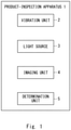
- Fig. 1 is a block diagram showing a minimum configuration of a product-inspection apparatus according to this example embodiment.
- the product-inspection apparatus 1 includes a vibration unit 2, a light source 3, an imaging unit 4, and a determination unit 5.
- the vibration unit 2 vibrates an object to be inspected, which is an object in which a powder is contained in a container, at different vibration frequencies in a stepwise manner.
- the vibration frequency at which a foreign substance floats changes depending on, for example, the relation (e.g., the ratio or the like) between the average product size of the powder and the volume of the foreign substance that it is presumed may possibly enter the object to be inspected. Therefore, a plurality of vibration frequencies are set in advance based on the average product size of the powder and the volume of foreign substances that it is presumed may possibly enter the object to be inspected.
- the light source 3 applies light onto the upper surface of the powder.
- the imaging unit 4 takes an image of the upper surface of the powder at a frame rate equal to or higher than the maximum vibration frequency of the vibration unit 2.
- the determination unit 5 determines whether or not the object to be inspected is a quality product based on the image information taken by the imaging unit 4.
- Fig. 2 is a flowchart showing an inspection method according to this example embodiment.
- the vibrations of the object to be inspected by the vibration unit 2 are started (S1).
- one of a plurality of vibration frequencies that are set in advance is selected, and the object to be inspected is vibrated at the selected vibration frequency.
- image information is acquired by photographing the upper surface of the powder of the vibrating object to be inspected (S2). More specifically, the upper surface of the powder of the vibrating object to be inspected is photographed by the imaging unit 4 while applying light onto the upper surface of the powder by the light source 3.
- the determination unit 5 determines whether or not the object to be inspected is a quality product based on the acquired image information (S3). Note that when a foreign substance that has a sufficient volume to make that foreign substance float as the object to be inspected is vibrated at the vibration frequency is contained in the powder, the foreign substance floats in the powder and is exposed from the upper surface of the powder.
- the determination unit 5 determines that the foreign substance is contained in the object to be inspected, and determines that the object to be inspected is a defective product (No in S3).
- the determination unit 5 determines that no foreign substance is contained in the object to be inspected, and determines that the object to be inspected is a quality product (Yes in S3).
- the operation for inspecting the object to be inspected is finished.
- the product-inspection apparatus 1 and the inspection method according to this example embodiment it is possible to detect foreign substances having different volumes contained in the object to be inspected by vibrating the object to be inspected at different vibration frequencies in a stepwise manner. Therefore, the product-inspection apparatus 1 and the product-inspection method according to this example embodiment can improve the accuracy of the product-inspection of an object to be inspected.
- FIG. 3 shows a specific configuration of a product-inspection apparatus according to this example embodiment.
- the object to be inspected 6 is sealed by a plug 6c in a state in which a powder 6b is contained in a transparent container 6a.
- the object to be inspected 6 may have an arbitrary configuration as long as the powder 6b is hermetically contained in the container 6a and the container 6a is optically transparent.
- the vibration unit 2 vibrates the object to be inspected 6 in the vertical direction.
- the vibration unit 2 includes, for example, a stage 2a on which the object to be inspected 6 is placed, and is configured to vibrate the stage 2a in the vertical direction. Note that although details of its function will be described later, the stage 2a may be configured so as to rotate around a rotation axis extending in the vertical direction.
- the light source 3 applies light having a wavelength range that passes through the container 6a to substantially the entire area on the upper surface of the powder 6b.
- one light source 3 may irradiate substantially the entire area on the upper surface of the powder 6b from one direction, or a plurality of light sources 3 may irradiate substantially the entire area on the upper surface of the powder 6b from a plurality of directions.
- substantially the entire area on the upper surface of the powder 6b may be irradiated with light by using a ring light or the like as the light source 3.
- the imaging unit 4 includes an image sensor such as a CMOS (Complementary Metal Oxide Semiconductor) or a CCD (Charge Coupled Device), and takes an image of substantially the entire area on the upper surface of the powder 6b. Then, the imaging unit 4 outputs the acquired image information to the determination unit 5.
- CMOS Complementary Metal Oxide Semiconductor
- CCD Charge Coupled Device
- the determination unit 5 determines whether or not the object to be inspected 6 is a quality product based on the image information acquired as described above, and is disposed, for example, in a processing apparatus 7.
- the processing apparatus 7 includes a control unit 8 in addition to the determination unit 5.
- the control unit 8 controls the vibration unit 2, the light source 3, and the imaging unit 4 (which will be described later in detail).
- the control unit 8 may control the display unit 9 so that the acquired image information is displayed in the display unit 9.
- the display unit 9 includes a display device such as an ordinary liquid-crystal display panel or an organic EL (Electro Luminescence) panel.
- the display unit 9 is equipped with a touch panel disposed on the display device, an inspector can make various settings (e.g., the setting of a plurality of vibration frequencies, the setting of the amplitude of vibrations of the object to be inspected 6, and the like) through the display unit 9.
- the product-inspection apparatus 1 may need to be equipped with an input unit by which an inspector makes various settings.
- FIG. 4 is a flowchart showing a specific flow of a product-inspection method according to this example embodiment.
- the vibration frequency at which a foreign substance floats changes depending on the relation between the average product size of the powder 6b and the volume of the foreign substance that it is presumed may possibly enter the object to be inspected 6. Therefore, a plurality of vibration frequencies are set based on the average product size of the powder 6b and the volume of foreign substances that it is presumed may possibly enter the object to be inspected 6.
- the vibration frequency is set to a frequency no lower than 10 Hz and no higher than 500 Hz.
- the amplitude of vibrations of the object to be inspected 6 is set to an amplitude at least 10 times the average product size of the powder 6b.
- the amplitude of vibrations of the object to be inspected 6 may be any amplitude at which the foreign substance floats.
- the average product size can be calculated beforehand by an image analysis method, a light shielding method, a Coulter method, a precipitation method, a laser analysis, a scattering method, or the like. That is, it is possible to calculate the average product size by using an ordinary method for calculating a product diameter.
- the control unit 8 sets a frame rate of the imaging unit 4 based on the set vibration frequency (S12). If the frame rate is small relative to the vibration frequency, there is a possibility that an image is taken at the moment at which a foreign substance that has been exposed from the upper surface of the powder 6b by vibrating the object to be inspected 6 goes down (i.e., is submerged) into the powder 6b again. Therefore, the control unit 8 sets the frame rate to a value equal to or higher than the maximum vibration frequency of the set vibration frequency range. For example, the control unit 8 sets the frame rate of the imaging unit 4 to 100 fps.
- control unit 8 sets the rotation speed of the stage 2a of the vibration unit 2 based on the set frame rate (S13). For example, when the thickness of a long and thin foreign substance such as hair is smaller than one pixel of the imaging unit 4, the imaging unit 4 may not be able to take an image of that foreign substance in a satisfactory manner even when it photographs the foreign substance from the longitudinal direction of the foreign substance.
- the control unit 8 makes a setting based on the set frame rate so that the imaging unit 4 can photograph the object to be inspected 6 at least three times while the stage 2a of the vibration unit 2 makes one rotation.
- the stage 2a of the vibration unit 2 may have any rotation speed as long as it does not have such a rotation speed that only parts of the object to be inspected 6 opposite to each other are photographed due to the rotation of the stage 2a.
- the stage 2a is rotated while being vibrated in a state where the object to be inspected 6 is placed on the stage 2a so that the center of the object to be inspected 6 is roughly positioned on the rotation axis of the vibration unit 2 as viewed in the vertical direction (S14).
- control unit 8 selects one of a plurality of vibration frequencies that are set in advance, and rotates the stage 2a at the set rotation speed of the stage 2a while vibrating the stage 2a at the selected vibration frequency and at the set amplitude. In this way, it is possible rotate the object to be inspected 6 around the rotation axis of the vibration unit 2 (i.e., rotate the object to be inspected 6 on its own axis) while vibrating it.
- the control unit 8 controls the light source 3 so as to apply light onto substantially the entire area on the upper surface of the powder 6b of the object to be inspected 6, which is rotating while vibrating, and controls the imaging unit 4 so as to take an image of substantially the entire area on the upper surface of the powder 6b (S15).
- the imaging unit 4 acquires image information including at least three images at roughly equal intervals in the circumferential direction of the object to be inspected 6, and outputs the acquired image information to the determination unit 5.
- Fig. 5 shows image information that is obtained by photographing the upper surface of the powder.
- the speed at which a foreign substance 6d, which it is presumed may possibly enter the object to be inspected 6, floats up inside the powder 6b is changed depending on the specific gravity of the foreign substance 6d. Therefore, it is preferred to acquire a plurality of periods over each of which a foreign substance 6d, which it is presumed may possibly enter the object to be inspected 6, moves from the bottom surface of the container 6a to the upper surface of the powder 6b in advance by performing simulations or experiments, and then to rotate the object to be inspected 6 while vibrating it over a period longer than the longest one of the acquired periods. As a result, as shown in Fig. 5 , the foreign substance 6d is exposed on the upper surface of the powder 6b.
- the above-described period over which the object to be inspected 6 is rotated while being vibrated may be set in advance, or may be set by an inspector through the display unit 9.
- the determination unit 5 determines whether or not a foreign substance 6d is detected based on the image information (S16). More specifically, the determination unit 5 calculates a difference between the pixel values of pixels that correspond to each other (i.e., equivalent pixels) in pieces of image information that are adjacent to each other in a chronological order (i.e., calculates an inter-frame difference), and determines whether or not there is an inter-frame difference larger than a predetermined threshold. Note that the inter-frame difference and the threshold have absolute values.
- the determination unit 5 determines that a foreign substance 6d is detected (Yes in S16), and outputs a result of determination that the object to be inspected 6 is a defective product to the control unit 8 (S17).
- the control unit 8 receives the result of determination that the object to be inspected 6 is a defective product, it moves out the object to be inspected 6 into a defective-product lane by controlling, for example, a robot arm (not shown), and finishes the product-inspection operation.
- the determination unit 5 determines that no foreign substance 6d is detected (No in S16), and outputs a result of determination that the object to be inspected 6 is a quality product to the control unit 8 (S18).
- control unit 8 when the control unit 8 receives the result of determination that the object to be inspected 6 is a quality product, it determines whether or not the object to be inspected 6 has been vibrated at all the set vibration frequencies (S19). When the control unit 8 determines that the object to be inspected 6 has been vibrated at all the set vibration frequencies (Yes in S19), it moves out the object to be inspected 6 into a quality-product lane by controlling, for example, a robot arm (not shown), and finishes the product-inspection operation.
- control unit 8 determines that the object to be inspected 6 has not been vibrated at all the set vibration frequencies (No in S19), it performs the steps S14 to S19 at a different vibration frequency.
- control unit 8 may calculate an average value of inter-frame differences at all the pixels in the previous vibration operation for the object to be inspected 6 (S20), and may subtract the calculated average value of inter-frame differences at the pixels in the previous vibration operation from the calculated inter-frame differences at the pixels in the current vibration operation.
- the product-inspection apparatus 1 and the product-inspection method according to this example embodiment it is possible to detect foreign substances 6d having different volumes contained in the object to be inspected by vibrating the object to be inspected 6 at different vibration frequencies in a stepwise manner. Therefore, the product-inspection apparatus 1 and the product-inspection method according to this example embodiment can improve the accuracy of the product-inspection of an object to be inspected 6.
- a plurality of parts of the object to be inspected 6 in the circumferential direction thereof are photographed (i.e., the object to be inspected 6 is photographed from different directions) while the object to be inspected 6 is rotated so that the object to be inspected 6 makes one rotation. Therefore, even if the foreign substance 6d is a long and thin product such as hair and the foreign substance 6d cannot be photographed in one piece of image information, the foreign substance 6d can be photographed in other pieces of image information. Therefore, it is possible to improve the accuracy of the product-inspection of an object to be inspected 6.
- the possibility that the foreign substance 6d can be photographed at the moment at which the foreign substance 6d is exposed on the upper surface of the powder 6b is high.
- inter-frame differences between pixels corresponding to each other in pieces of image information adjacent to each other in a chronological order are smaller than those in a group of pixels corresponding to a part on the upper surface of the powder 6b where no shadow appears.
- the steps of S11 to S15 are performed in advance by using the object to be inspected 6 as a sample. Then, based on the acquired image information, the pixels are divided into a first group of pixels corresponding to a part on the upper surface of the powder 6b where a shadow appears and a second group of pixels corresponding to a part where no shadow appears.
- inter-frame differences between pixels corresponding to each other in pieces of image information adjacent to each other in a chronological order are calculated, and an average value of inter-frame differences in the first group of pixels and an average value of inter-frame differences in the second group of pixels are calculated.
- a ratio of the average value of inter-frame differences in the second group of pixels to the average value of inter-frame differences in the first group of pixels may be calculated. Then, when the object to be inspected 6 is inspected, the pixel values of pixels in the first group of pixels may be corrected by multiplexing them by the calculated ratio.
- a value that is obtained by dividing the threshold used for detecting a foreign substance 6d in the second group of pixels by the calculated ratio may be used as the threshold used for detecting a foreign substance 6d in the first group of pixels. That is, the threshold used for detecting a foreign substance 6d in the first group of pixels may be made smaller than the threshold used for detecting a foreign substance 6d in the second group of pixels by a factor of the calculated ratio.
- the present invention is described as a hardware configuration in the above-described first and second example embodiments, the present invention is not limited to the hardware configurations.
- the processes in each of the components can also be implemented by having a CPU (Central Processing Unit) execute a computer program.
- CPU Central Processing Unit
- the processing apparatus 7 can have the below-shown hardware configuration.
- Fig. 6 shows an example of a hardware configuration included in the processing apparatus 7.
- An apparatus 70 shown in Fig. 6 includes a processor 72 and a memory 73 as well as an interface 71.
- the processing apparatus 7 described in the above example embodiments is implemented as the processor 72 loads and executes a program stored in the memory 73. That is, this program is a program for causing the processor 72 to function as the processing apparatus 7 shown in Fig. 3 .
- Non-transitory computer readable media include various types of tangible storage media.
- Examples of the non-transitory computer readable media include magnetic recording media (e.g., a flexible disk, a magnetic tape, and a hard disk drive), and magneto-optical recording media (e.g., a magneto-optical disk).
- the example includes a CD-ROM (Read Only Memory), a CD-R, and a CD-R/W.
- the example includes a semiconductor memory (e.g., a mask ROM, a PROM, an EPROM, a flash ROM, and a RAM).
- the program may be supplied to a computer by various types of transitory computer readable media).
- Examples of the transitory computer readable media include an electrical signal, an optical signal, and electromagnetic waves.
- Transitory computer readable media can provide the program to a computer via a wired communication line (e.g., electric wires, and optical fibers) or a wireless communication line.
- present disclosure is not limited to the above-described example embodiments, and they may be modified as desired without departing from the scope and spirit of the disclosure. Further, the present disclosure may be implemented by combining the above-described example embodiments with one another as desired.
- a plurality of different parts of the object to be inspected 6 in the circumferential direction thereof are photographed by rotating the object to be inspected 6.
- a plurality of different parts of the object to be inspected 6 in the circumferential direction thereof may be photographed by arranging a plurality of imaging units 4 around the object to be inspected 6 without rotating the object to be inspected 6.
- the object to be inspected 6 is rotated on its own axis which coincides with the rotation axis of the vibration unit 2.
- the object to be inspected 6 may be poisoned so that the object to be inspected 6 revolves around the rotation axis of the vibration unit 2.
- any configuration may be used as long as different parts of the object to be inspected 6 in the circumferential direction thereof can be photographed.
- the vibration frequency is set according to the average product size of the powder 6b and the volume of foreign substances 6d that it is presumed may possibly enter the object to be inspected 6.
- the vibration frequency may be set according to the distribution of product sizes of the powder 6b and the volume of foreign substances 6d that it is presumed may possibly enter the object to be inspected 6.
- the vibration frequency may be set according to the surface area or the volume of the powder 6b and the volume of foreign substances 6d that it is presumed may possibly enter the object to be inspected 6.
- the vibration frequency may be set according to the friction between the powder 6b and the object to be inspected 6.
- the vibration unit 2 may be configured so as to grasp the object to be inspected 6, and to vibrate and/or rotate the object to be inspected 6 in the holding state. Further, the vibration unit 2 may be, for example, a conveyance table for the object to be inspected 6 disposed in a conveyance line for the object to be inspected 6. To put it briefly, the vibration unit 2 may have any configuration as long as it can vibrate at least the object to be inspected 6.
Landscapes
- Engineering & Computer Science (AREA)
- Physics & Mathematics (AREA)
- General Physics & Mathematics (AREA)
- Computer Vision & Pattern Recognition (AREA)
- Theoretical Computer Science (AREA)
- Health & Medical Sciences (AREA)
- General Health & Medical Sciences (AREA)
- Multimedia (AREA)
- Chemical & Material Sciences (AREA)
- Life Sciences & Earth Sciences (AREA)
- Pathology (AREA)
- Immunology (AREA)
- Biochemistry (AREA)
- Analytical Chemistry (AREA)
- Medical Informatics (AREA)
- Mechanical Engineering (AREA)
- Software Systems (AREA)
- Quality & Reliability (AREA)
- Evolutionary Computation (AREA)
- Databases & Information Systems (AREA)
- Computing Systems (AREA)
- Artificial Intelligence (AREA)
- Signal Processing (AREA)
- Investigating Materials By The Use Of Optical Means Adapted For Particular Applications (AREA)
Abstract
Description
- The present disclosure relates to a product-inspection apparatus, a product-inspection method, and a non-transitory computer readable medium.
- An ordinary product-inspection apparatus is configured to determine whether or not an object to be inspected, which is an object in which an object to be contained is contained in a container, is a quality product by determining whether or not a foreign substance is contained in the object to be inspected. For example, a product-inspection apparatus disclosed in
Patent Literature 1 is configured to, while applying vertical and horizontal vibrations to an object to be inspected, which is an object in which a powder is contained in a transparent container, and thereby making the powder circulate and flow therein, take an image of the circulating and flowing powder through a wall surface of the transparent container in which the powder is in contact with the inner surface thereof, and thereby to determine whether or not a foreign substance is contained in the object to be inspected based on the taken image information. - Patent Literature 1:
Japanese Patent No. 5307459 - Regarding the ordinary product-inspection apparatus, there are cases in which foreign substances having different volumes may not be satisfactorily detected, thus causing a problem that the accuracy of the product-inspection of an object to be inspected is poor.
- One of the objects that example embodiments disclosed in this specification are intended to achieve is to provide a product-inspection apparatus, a product-inspection method, and a non-transitory computer readable medium capable of contributing to solving the above-described problem. Note that the aforementioned object is merely one of a plurality of objects that a plurality of example embodiments disclosed in this specification are intended to achieve. Other objects or problems and novel features will be made apparent from the following description in this specification and the accompanying drawings.
- A product-inspection apparatus according to a first aspect includes:
- a vibration unit configured to vibrate an object to be inspected at different vibration frequencies in a stepwise manner, the object to be inspected being an object in which a powder is contained in a container;
- a light source configured to apply light onto an upper surface of the powder;
- an imaging unit configured to take an image of the upper surface of the powder at a frame rate equal to or higher than a maximum vibration frequency of the vibration unit; and
- a determination unit configured to determine whether or not the object to be inspected is a quality product based on image information taken by the imaging unit.
- A product-inspection method according to a second aspect includes:
- vibrating an object to be inspected at different vibration frequencies in a stepwise manner, the object to be inspected being an object in which a powder is contained in a container;
- applying light onto an upper surface of the powder;
- taking an image of the upper surface of the powder at a frame rate equal to or higher than a maximum vibration frequency among the stepwise-changed vibration frequencies; and
- determining whether or not the object to be inspected is a quality product based on the taken image information.
- A non-transitory computer readable medium according to a third aspect stores a program for causing a computer to:
- vibrate an object to be inspected at different vibration frequencies in a stepwise manner, the object to be inspected being an object in which a powder is contained in a container;
- apply light onto an upper surface of the powder;
- take an image of the upper surface of the powder at a frame rate equal to or higher than a maximum vibration frequency among the stepwise-changed vibration frequencies; and
- determine whether or not the object to be inspected is a quality product based on the taken image information.
- According to the above-described aspects, it is possible to provide a product-inspection apparatus, a product-inspection method, and a non-transitory computer readable medium capable of contributing to the improvement of the accuracy of detection in an object to be inspected.
-
-
Fig. 1 is a block diagram showing a minimum configuration of a product-inspection apparatus according to a first example embodiment; -
Fig. 2 is a flowchart showing an inspection method according to the first example embodiment; -
Fig. 3 shows a specific configuration of a product-inspection apparatus according to the first example embodiment; -
Fig. 4 is a flowchart showing a specific flow of a product-inspection method according to the first example embodiment; -
Fig. 5 shows information of an image of the upper surface of a powder; and -
Fig. 6 shows an example of a hardware configuration included in a processing apparatus. - A best mode for carrying out the present disclosure will be described hereinafter with reference to the accompanying drawings. However, the present disclosure is not limited to the below-shown example embodiments. Further, to clarify the explanation, the following description and drawings are simplified as appropriate.
- In a product-inspection apparatus and a product-inspection method according to this example embodiment, a foreign substance contained in an object to be inspected, which is an object in which a powder is hermetically contained in a container, is made to float in the powder by vibrating the object to be inspected, so that the foreign substance is exposed from the upper surface of the powder. By doing so, the foreign substance contained in the object to be inspected is detected.
- Powder medicines such as oral medicines or injection medicines are suitable as the powder. However, the powder may be any substance in a powdery form, and may be a foodstuff or the like. The container is an optically-transparent vial, an optically transparent ampule, or an optically transparent test tube. The foreign substance is a substance different from the powder. Examples of the foreign substance include a piece of a fiber such as a cloth, a piece of hair falling from a human body, a piece of metal such as a piece of a component in a production line for the object to be inspected or the like, and a piece of resin and a piece of glass such as a piece of a container.
- Firstly, a minimum configuration of a product-inspection apparatus according to this example embodiment will be described.
Fig. 1 is a block diagram showing a minimum configuration of a product-inspection apparatus according to this example embodiment. As shown inFig. 1 , the product-inspection apparatus 1 includes avibration unit 2, alight source 3, animaging unit 4, and adetermination unit 5. Thevibration unit 2 vibrates an object to be inspected, which is an object in which a powder is contained in a container, at different vibration frequencies in a stepwise manner. - Note that the vibration frequency at which a foreign substance floats changes depending on, for example, the relation (e.g., the ratio or the like) between the average product size of the powder and the volume of the foreign substance that it is presumed may possibly enter the object to be inspected. Therefore, a plurality of vibration frequencies are set in advance based on the average product size of the powder and the volume of foreign substances that it is presumed may possibly enter the object to be inspected.
- The
light source 3 applies light onto the upper surface of the powder. Theimaging unit 4 takes an image of the upper surface of the powder at a frame rate equal to or higher than the maximum vibration frequency of thevibration unit 2. Thedetermination unit 5 determines whether or not the object to be inspected is a quality product based on the image information taken by theimaging unit 4. - Next, an inspection method using a product-inspection apparatus according to this example embodiment will be described.
Fig. 2 is a flowchart showing an inspection method according to this example embodiment. Firstly, the vibrations of the object to be inspected by thevibration unit 2 are started (S1). In this process, one of a plurality of vibration frequencies that are set in advance is selected, and the object to be inspected is vibrated at the selected vibration frequency. - Then, image information is acquired by photographing the upper surface of the powder of the vibrating object to be inspected (S2). More specifically, the upper surface of the powder of the vibrating object to be inspected is photographed by the
imaging unit 4 while applying light onto the upper surface of the powder by thelight source 3. - Next, the
determination unit 5 determines whether or not the object to be inspected is a quality product based on the acquired image information (S3). Note that when a foreign substance that has a sufficient volume to make that foreign substance float as the object to be inspected is vibrated at the vibration frequency is contained in the powder, the foreign substance floats in the powder and is exposed from the upper surface of the powder. - Therefore, when a foreign substance is detected on the upper surface of the powder based on the acquired image information, the
determination unit 5 determines that the foreign substance is contained in the object to be inspected, and determines that the object to be inspected is a defective product (No in S3). On the other hand, when no foreign substance is detected on the upper surface of the powder based on the acquired image information, thedetermination unit 5 determines that no foreign substance is contained in the object to be inspected, and determines that the object to be inspected is a quality product (Yes in S3). - After that, when the above-described steps S1 to S3 are repeated at different vibration frequencies in a stepwise manner, i.e., repeated for all of the plurality of pre-set vibration frequencies, the operation for inspecting the object to be inspected is finished. As described above, in the product-
inspection apparatus 1 and the inspection method according to this example embodiment, it is possible to detect foreign substances having different volumes contained in the object to be inspected by vibrating the object to be inspected at different vibration frequencies in a stepwise manner. Therefore, the product-inspection apparatus 1 and the product-inspection method according to this example embodiment can improve the accuracy of the product-inspection of an object to be inspected. - Next, a specific configuration of the product-
inspection apparatus 1 according to this example embodiment will be described.Fig. 3 shows a specific configuration of a product-inspection apparatus according to this example embodiment. Note that, as shown inFig. 3 , for example, the object to be inspected 6 is sealed by aplug 6c in a state in which apowder 6b is contained in atransparent container 6a. However, the object to be inspected 6 may have an arbitrary configuration as long as thepowder 6b is hermetically contained in thecontainer 6a and thecontainer 6a is optically transparent. - When the direction of the gravity is defined as a downward direction, the
vibration unit 2 vibrates the object to be inspected 6 in the vertical direction. Thevibration unit 2 includes, for example, astage 2a on which the object to be inspected 6 is placed, and is configured to vibrate thestage 2a in the vertical direction. Note that although details of its function will be described later, thestage 2a may be configured so as to rotate around a rotation axis extending in the vertical direction. - The
light source 3 applies light having a wavelength range that passes through thecontainer 6a to substantially the entire area on the upper surface of thepowder 6b. Note that onelight source 3 may irradiate substantially the entire area on the upper surface of thepowder 6b from one direction, or a plurality oflight sources 3 may irradiate substantially the entire area on the upper surface of thepowder 6b from a plurality of directions. Alternatively, substantially the entire area on the upper surface of thepowder 6b may be irradiated with light by using a ring light or the like as thelight source 3. - The
imaging unit 4 includes an image sensor such as a CMOS (Complementary Metal Oxide Semiconductor) or a CCD (Charge Coupled Device), and takes an image of substantially the entire area on the upper surface of thepowder 6b. Then, theimaging unit 4 outputs the acquired image information to thedetermination unit 5. - The
determination unit 5 determines whether or not the object to be inspected 6 is a quality product based on the image information acquired as described above, and is disposed, for example, in a processing apparatus 7. The processing apparatus 7 includes acontrol unit 8 in addition to thedetermination unit 5. Thecontrol unit 8 controls thevibration unit 2, thelight source 3, and the imaging unit 4 (which will be described later in detail). - Note that when a
display unit 9 is electrically connected to the processing apparatus 7, thecontrol unit 8 may control thedisplay unit 9 so that the acquired image information is displayed in thedisplay unit 9. Thedisplay unit 9 includes a display device such as an ordinary liquid-crystal display panel or an organic EL (Electro Luminescence) panel. - Note that when the
display unit 9 is equipped with a touch panel disposed on the display device, an inspector can make various settings (e.g., the setting of a plurality of vibration frequencies, the setting of the amplitude of vibrations of the object to be inspected 6, and the like) through thedisplay unit 9. However, the product-inspection apparatus 1 may need to be equipped with an input unit by which an inspector makes various settings. - Next, a specific flow of a product-inspection method according to this example embodiment will be described.
Fig. 4 is a flowchart showing a specific flow of a product-inspection method according to this example embodiment. Firstly, an inspector sets a plurality of vibration frequencies and the amplitude of vibrations of an object to be inspected 6 through the display unit 9 (S11). - More specifically, the vibration frequency at which a foreign substance floats changes depending on the relation between the average product size of the
powder 6b and the volume of the foreign substance that it is presumed may possibly enter the object to be inspected 6. Therefore, a plurality of vibration frequencies are set based on the average product size of thepowder 6b and the volume of foreign substances that it is presumed may possibly enter the object to be inspected 6. - For example, the vibration frequency is set to a frequency no lower than 10 Hz and no higher than 500 Hz. Further, the amplitude of vibrations of the object to be inspected 6 is set to an amplitude at least 10 times the average product size of the
powder 6b. However, the amplitude of vibrations of the object to be inspected 6 may be any amplitude at which the foreign substance floats. - Note that the average product size can be calculated beforehand by an image analysis method, a light shielding method, a Coulter method, a precipitation method, a laser analysis, a scattering method, or the like. That is, it is possible to calculate the average product size by using an ordinary method for calculating a product diameter.
- Next, when a plurality of vibration frequencies and the amplitude of vibrations of the object to be inspected 6 are set, the
control unit 8 sets a frame rate of theimaging unit 4 based on the set vibration frequency (S12). If the frame rate is small relative to the vibration frequency, there is a possibility that an image is taken at the moment at which a foreign substance that has been exposed from the upper surface of thepowder 6b by vibrating the object to be inspected 6 goes down (i.e., is submerged) into thepowder 6b again. Therefore, thecontrol unit 8 sets the frame rate to a value equal to or higher than the maximum vibration frequency of the set vibration frequency range. For example, thecontrol unit 8 sets the frame rate of theimaging unit 4 to 100 fps. - Next, the
control unit 8 sets the rotation speed of thestage 2a of thevibration unit 2 based on the set frame rate (S13). For example, when the thickness of a long and thin foreign substance such as hair is smaller than one pixel of theimaging unit 4, theimaging unit 4 may not be able to take an image of that foreign substance in a satisfactory manner even when it photographs the foreign substance from the longitudinal direction of the foreign substance. - Therefore, the
control unit 8 makes a setting based on the set frame rate so that theimaging unit 4 can photograph the object to be inspected 6 at least three times while thestage 2a of thevibration unit 2 makes one rotation. However, thestage 2a of thevibration unit 2 may have any rotation speed as long as it does not have such a rotation speed that only parts of the object to be inspected 6 opposite to each other are photographed due to the rotation of thestage 2a. - Next, by controlling the
vibration unit 2, thestage 2a is rotated while being vibrated in a state where the object to be inspected 6 is placed on thestage 2a so that the center of the object to be inspected 6 is roughly positioned on the rotation axis of thevibration unit 2 as viewed in the vertical direction (S14). - In this process, the
control unit 8 selects one of a plurality of vibration frequencies that are set in advance, and rotates thestage 2a at the set rotation speed of thestage 2a while vibrating thestage 2a at the selected vibration frequency and at the set amplitude. In this way, it is possible rotate the object to be inspected 6 around the rotation axis of the vibration unit 2 (i.e., rotate the object to be inspected 6 on its own axis) while vibrating it. - Then, the
control unit 8 controls thelight source 3 so as to apply light onto substantially the entire area on the upper surface of thepowder 6b of the object to be inspected 6, which is rotating while vibrating, and controls theimaging unit 4 so as to take an image of substantially the entire area on the upper surface of thepowder 6b (S15). In this way, theimaging unit 4 acquires image information including at least three images at roughly equal intervals in the circumferential direction of the object to be inspected 6, and outputs the acquired image information to thedetermination unit 5. Note thatFig. 5 shows image information that is obtained by photographing the upper surface of the powder. - It should be noted that the speed at which a
foreign substance 6d, which it is presumed may possibly enter the object to be inspected 6, floats up inside thepowder 6b is changed depending on the specific gravity of theforeign substance 6d. Therefore, it is preferred to acquire a plurality of periods over each of which aforeign substance 6d, which it is presumed may possibly enter the object to be inspected 6, moves from the bottom surface of thecontainer 6a to the upper surface of thepowder 6b in advance by performing simulations or experiments, and then to rotate the object to be inspected 6 while vibrating it over a period longer than the longest one of the acquired periods. As a result, as shown inFig. 5 , theforeign substance 6d is exposed on the upper surface of thepowder 6b. The above-described period over which the object to be inspected 6 is rotated while being vibrated may be set in advance, or may be set by an inspector through thedisplay unit 9. - Next, the
determination unit 5 determines whether or not aforeign substance 6d is detected based on the image information (S16). More specifically, thedetermination unit 5 calculates a difference between the pixel values of pixels that correspond to each other (i.e., equivalent pixels) in pieces of image information that are adjacent to each other in a chronological order (i.e., calculates an inter-frame difference), and determines whether or not there is an inter-frame difference larger than a predetermined threshold. Note that the inter-frame difference and the threshold have absolute values. - When there is an inter-frame difference equal to or larger than the predetermined threshold, the
determination unit 5 determines that aforeign substance 6d is detected (Yes in S16), and outputs a result of determination that the object to be inspected 6 is a defective product to the control unit 8 (S17). When thecontrol unit 8 receives the result of determination that the object to be inspected 6 is a defective product, it moves out the object to be inspected 6 into a defective-product lane by controlling, for example, a robot arm (not shown), and finishes the product-inspection operation. - On the other hand, when there is no inter-frame difference equal to or greater than the predetermined threshold, the
determination unit 5 determines that noforeign substance 6d is detected (No in S16), and outputs a result of determination that the object to be inspected 6 is a quality product to the control unit 8 (S18). - Next, when the
control unit 8 receives the result of determination that the object to be inspected 6 is a quality product, it determines whether or not the object to be inspected 6 has been vibrated at all the set vibration frequencies (S19). When thecontrol unit 8 determines that the object to be inspected 6 has been vibrated at all the set vibration frequencies (Yes in S19), it moves out the object to be inspected 6 into a quality-product lane by controlling, for example, a robot arm (not shown), and finishes the product-inspection operation. - On the other hand, when the
control unit 8 determines that the object to be inspected 6 has not been vibrated at all the set vibration frequencies (No in S19), it performs the steps S14 to S19 at a different vibration frequency. Note that thecontrol unit 8 may calculate an average value of inter-frame differences at all the pixels in the previous vibration operation for the object to be inspected 6 (S20), and may subtract the calculated average value of inter-frame differences at the pixels in the previous vibration operation from the calculated inter-frame differences at the pixels in the current vibration operation. In this way, even if the upper surface of thepowder 6b has been deformed due to the vibrations when the object to be inspected 6 is making one rotation and this deformation has affected the inter-frame differences, it is possible prevent the deformation from being mistakenly detected as aforeign substance 6d. - As described above, in the product-
inspection apparatus 1 and the product-inspection method according to this example embodiment, it is possible to detectforeign substances 6d having different volumes contained in the object to be inspected by vibrating the object to be inspected 6 at different vibration frequencies in a stepwise manner. Therefore, the product-inspection apparatus 1 and the product-inspection method according to this example embodiment can improve the accuracy of the product-inspection of an object to be inspected 6. - In addition, a plurality of parts of the object to be inspected 6 in the circumferential direction thereof are photographed (i.e., the object to be inspected 6 is photographed from different directions) while the object to be inspected 6 is rotated so that the object to be inspected 6 makes one rotation. Therefore, even if the
foreign substance 6d is a long and thin product such as hair and theforeign substance 6d cannot be photographed in one piece of image information, theforeign substance 6d can be photographed in other pieces of image information. Therefore, it is possible to improve the accuracy of the product-inspection of an object to be inspected 6. - Further, since the upper surface of the
powder 6b is photographed at a frame rate equal to or higher than the maximum vibration frequency, the possibility that theforeign substance 6d can be photographed at the moment at which theforeign substance 6d is exposed on the upper surface of thepowder 6b is high. - When light is applied onto the upper surface of the
powder 6b by thelight source 3, there is a possibility that a shadow of thecontainer 6a appears on the upper surface of thepowder 6b. Further, in the configuration of the product-inspection apparatus 1 according to the first example embodiment, the shadow of thecontainer 6a appears in a fixed place on the upper surface of thepowder 6b. - Note that in a group of pixels corresponding to the part on the upper surface of the
powder 6b where the shadow appears, inter-frame differences between pixels corresponding to each other in pieces of image information adjacent to each other in a chronological order are smaller than those in a group of pixels corresponding to a part on the upper surface of thepowder 6b where no shadow appears. - Therefore, the steps of S11 to S15 are performed in advance by using the object to be inspected 6 as a sample. Then, based on the acquired image information, the pixels are divided into a first group of pixels corresponding to a part on the upper surface of the
powder 6b where a shadow appears and a second group of pixels corresponding to a part where no shadow appears. - Then, inter-frame differences between pixels corresponding to each other in pieces of image information adjacent to each other in a chronological order are calculated, and an average value of inter-frame differences in the first group of pixels and an average value of inter-frame differences in the second group of pixels are calculated.
- Further, for example, a ratio of the average value of inter-frame differences in the second group of pixels to the average value of inter-frame differences in the first group of pixels may be calculated. Then, when the object to be inspected 6 is inspected, the pixel values of pixels in the first group of pixels may be corrected by multiplexing them by the calculated ratio.
- In this way, it is possible to cancel out the shadow that appears on the upper surface of the
powder 6b can, and thereby to prevent aforeign substance 6d from being un-detected due to the shadow. Note that a value that is obtained by dividing the threshold used for detecting aforeign substance 6d in the second group of pixels by the calculated ratio may be used as the threshold used for detecting aforeign substance 6d in the first group of pixels. That is, the threshold used for detecting aforeign substance 6d in the first group of pixels may be made smaller than the threshold used for detecting aforeign substance 6d in the second group of pixels by a factor of the calculated ratio. - Note that although the present invention is described as a hardware configuration in the above-described first and second example embodiments, the present invention is not limited to the hardware configurations. In the present invention, the processes in each of the components can also be implemented by having a CPU (Central Processing Unit) execute a computer program.
- For example, the processing apparatus 7 according to any of the above-described example embodiments can have the below-shown hardware configuration.
Fig. 6 shows an example of a hardware configuration included in the processing apparatus 7. - An
apparatus 70 shown inFig. 6 includes aprocessor 72 and amemory 73 as well as aninterface 71. The processing apparatus 7 described in the above example embodiments is implemented as theprocessor 72 loads and executes a program stored in thememory 73. That is, this program is a program for causing theprocessor 72 to function as the processing apparatus 7 shown inFig. 3 . - The above-described program may be stored by using various types of non-transitory computer readable media and supplied to a computer (computers including information notification apparatuses). Non-transitory computer readable media include various types of tangible storage media. Examples of the non-transitory computer readable media include magnetic recording media (e.g., a flexible disk, a magnetic tape, and a hard disk drive), and magneto-optical recording media (e.g., a magneto-optical disk). Further, the example includes a CD-ROM (Read Only Memory), a CD-R, and a CD-R/W. Further, the example includes a semiconductor memory (e.g., a mask ROM, a PROM, an EPROM, a flash ROM, and a RAM). Further, the program may be supplied to a computer by various types of transitory computer readable media). Examples of the transitory computer readable media include an electrical signal, an optical signal, and electromagnetic waves. Transitory computer readable media can provide the program to a computer via a wired communication line (e.g., electric wires, and optical fibers) or a wireless communication line.
- Note that the present disclosure is not limited to the above-described example embodiments, and they may be modified as desired without departing from the scope and spirit of the disclosure. Further, the present disclosure may be implemented by combining the above-described example embodiments with one another as desired.
- In the above-described example embodiments, a plurality of different parts of the object to be inspected 6 in the circumferential direction thereof are photographed by rotating the object to be inspected 6. However, a plurality of different parts of the object to be inspected 6 in the circumferential direction thereof may be photographed by arranging a plurality of
imaging units 4 around the object to be inspected 6 without rotating the object to be inspected 6. Further, the object to be inspected 6 is rotated on its own axis which coincides with the rotation axis of thevibration unit 2. However, the object to be inspected 6 may be poisoned so that the object to be inspected 6 revolves around the rotation axis of thevibration unit 2. To put it briefly, any configuration may be used as long as different parts of the object to be inspected 6 in the circumferential direction thereof can be photographed. - In the above-described example embodiments, the vibration frequency is set according to the average product size of the
powder 6b and the volume offoreign substances 6d that it is presumed may possibly enter the object to be inspected 6. However, the vibration frequency may be set according to the distribution of product sizes of thepowder 6b and the volume offoreign substances 6d that it is presumed may possibly enter the object to be inspected 6. Further, the vibration frequency may be set according to the surface area or the volume of thepowder 6b and the volume offoreign substances 6d that it is presumed may possibly enter the object to be inspected 6. Further, the vibration frequency may be set according to the friction between thepowder 6b and the object to be inspected 6. - Although the
vibration unit 2 according to the above-described example embodiments has a configuration in which the object to be inspected 6 is placed thereof, thevibration unit 2 may be configured so as to grasp the object to be inspected 6, and to vibrate and/or rotate the object to be inspected 6 in the holding state. Further, thevibration unit 2 may be, for example, a conveyance table for the object to be inspected 6 disposed in a conveyance line for the object to be inspected 6. To put it briefly, thevibration unit 2 may have any configuration as long as it can vibrate at least the object to be inspected 6. -
- 1
- PRODUCT-INSPECTION APPARATUS
- 2
- VIBRATION UNIT
- 2A
- STAGE
- 3
- LIGHT SOURCE
- 4
- IMAGING UNIT
- 5
- DETERMINATION UNIT
- 6
- OBJECT TO BE INSPECTED
- 6A
- CONTAINER
- 6B
- POWDER
- 6C
- PLUG
- 6D
- FOREIGN SUBSTANCE
- 7
- PROCESSING APPARATUS
- 8
- CONTROL UNIT
- 9
- DISPLAY UNIT
- 70
- APPARATUS
- 71
- INTERFACES
- 72
- PROCESSOR
- 73
- MEMORY
Claims (15)
- A product-inspection apparatus comprising:a vibration unit configured to vibrate an object to be inspected at different vibration frequencies in a stepwise manner, the object to be inspected being an object in which a powder is contained in a container;a light source configured to apply light onto an upper surface of the powder;an imaging unit configured to take an image of the upper surface of the powder at a frame rate equal to or higher than a maximum vibration frequency of the vibration unit; anda determination unit configured to determine whether or not the object to be inspected is a quality product based on image information taken by the imaging unit.
- The product-inspection apparatus according to Claim 1, wherein when a direction of gravity is defined as a downward direction, the vibration unit vibrates the object to be inspected in a vertical direction.
- The product-inspection apparatus according to Claim 1 or 2, wherein when a direction of gravity is defined as a downward direction, the vibrating unit rotates the object to be inspected so that the object to be inspected makes one rotation around a rotation axis extending in a vertical direction at each of vibration frequencies.
- The product-inspection apparatus according to Claim 3, wherein the imaging unit takes a plurality of images during the one rotation of the object to be inspected.
- The product-inspection apparatus according to Claim 4, wherein the imaging unit takes at least three images at equal intervals in a circumferential direction of the object to be inspected.
- The product-inspection apparatus according to any one of Claims 1 to 5, wherein the vibration frequency is set according to an average product size of the powder and a predetermined volume of a foreign substance that it is presumed may possibly enter the object to be inspected.
- The product-inspection apparatus according to any one of Claims 1 to 6, wherein the determination unit calculates a difference between pixels corresponding to each other in pieces of image information adjacent to each other in a chronological order, and determines that the object to be inspected is a defective product when the calculated difference is equal to or larger than a predetermined threshold.
- A product-inspection method comprising:vibrating an object to be inspected at different vibration frequencies in a stepwise manner, the object to be inspected being an object in which a powder is contained in a container;applying light onto an upper surface of the powder;taking an image of the upper surface of the powder at a frame rate equal to or higher than a maximum vibration frequency among the stepwise-changed vibration frequencies; anddetermining whether or not the object to be inspected is a quality product based on the taken image information.
- The product-inspection method according to Claim 8, wherein when a direction of gravity is defined as a downward direction, the object to be inspected is vibrated in a vertical direction.
- The product-inspection method according to Claim 8 or 9, wherein when a direction of gravity is defined as a downward direction, the object to be inspected is rotated so that the object to be inspected makes one rotation around a rotation axis extending in a vertical direction at each of vibration frequencies.
- The product-inspection method according to Claim 10, wherein a plurality of images are taken during the one rotation of the object to be inspected.
- The product-inspection method according to Claim 11, wherein at least three images are taken at equal intervals in a circumferential direction of the object to be inspected.
- The product-inspection method according to any one of Claims 8 to 12, wherein the vibration frequency is set according to an average product size of the powder and a predetermined volume of a foreign substance that it is presumed may possibly enter the object to be inspected.
- The product-inspection method according to any one of Claims 8 to 13, wherein a difference between pixels corresponding to each other in pieces of image information adjacent to each other in a chronological order is calculated, and it is determined that the object to be inspected is a defective product when the calculated difference is equal to or larger than a predetermined threshold.
- A non-transitory computer readable medium storing a program for causing a computer to:vibrate an object to be inspected at different vibration frequencies in a stepwise manner, the object to be inspected being an object in which a powder is contained in a container;apply light onto an upper surface of the powder;take an image of the upper surface of the powder at a frame rate equal to or higher than a maximum vibration frequency among the stepwise-changed vibration frequencies; anddetermine whether or not the object to be inspected is a quality product based on the taken image information.
Applications Claiming Priority (1)
| Application Number | Priority Date | Filing Date | Title |
|---|---|---|---|
| PCT/JP2019/011346 WO2020188728A1 (en) | 2019-03-19 | 2019-03-19 | Inspection device, inspection method, and non-transitory computer-readable medium |
Publications (3)
| Publication Number | Publication Date |
|---|---|
| EP3943921A1 true EP3943921A1 (en) | 2022-01-26 |
| EP3943921A4 EP3943921A4 (en) | 2022-03-16 |
| EP3943921B1 EP3943921B1 (en) | 2024-10-16 |
Family
ID=72519278
Family Applications (1)
| Application Number | Title | Priority Date | Filing Date |
|---|---|---|---|
| EP19920093.2A Active EP3943921B1 (en) | 2019-03-19 | 2019-03-19 | Inspection device, inspection method, and non-transitory computer-readable medium |
Country Status (4)
| Country | Link |
|---|---|
| US (1) | US11972555B2 (en) |
| EP (1) | EP3943921B1 (en) |
| JP (1) | JP7238964B2 (en) |
| WO (1) | WO2020188728A1 (en) |
Family Cites Families (17)
| Publication number | Priority date | Publication date | Assignee | Title |
|---|---|---|---|---|
| JPS52124064A (en) | 1976-04-12 | 1977-10-18 | Armstrong Cork Co | Method and device for producing sheet material |
| JPH01272948A (en) * | 1988-04-26 | 1989-10-31 | Mitsubishi Heavy Ind Ltd | Inspecting method for foreign matter in real bottle |
| JP2719410B2 (en) * | 1989-07-19 | 1998-02-25 | 日鉄鉱業株式会社 | Automatic inspection equipment for powder sealed transparent containers |
| JP2000298103A (en) * | 1999-04-15 | 2000-10-24 | Nittetsu Mining Co Ltd | Foreign particle inspection device for powder in transparent containers |
| JP4279945B2 (en) | 1999-06-24 | 2009-06-17 | 第一三共株式会社 | Foreign matter detection device in powder |
| JP2004257937A (en) * | 2003-02-27 | 2004-09-16 | Japan System Kk | Foreign matter inspection device and inspection method |
| JP2005030810A (en) * | 2003-07-08 | 2005-02-03 | Asahi Shuzo Kk | Foreign matter inspection device |
| JP5307459B2 (en) * | 2008-06-30 | 2013-10-02 | 株式会社 デクシス | Foreign matter inspection method and foreign matter inspection device in powder in transparent container |
| JP5479018B2 (en) * | 2009-10-09 | 2014-04-23 | ボッシュパッケージングテクノロジー株式会社 | Foreign object inspection apparatus and method |
| JP2012220453A (en) * | 2011-04-13 | 2012-11-12 | Eisai Machinery Co Ltd | Foreign matter detection device |
| JP5994416B2 (en) * | 2012-06-18 | 2016-09-21 | ニプロ株式会社 | Foreign matter detection device and foreign matter detection method in powder using terahertz pulse wave |
| JP2014006186A (en) * | 2012-06-26 | 2014-01-16 | Fuji Electric Co Ltd | Foreign matter inspection device |
| US9460119B2 (en) * | 2012-10-25 | 2016-10-04 | Nec Corporation | Information processing device, information processing method, and recording medium |
| JP6028919B2 (en) * | 2013-01-29 | 2016-11-24 | 富士電機株式会社 | Foreign matter inspection device |
| WO2018002049A1 (en) * | 2016-06-28 | 2018-01-04 | F. Hoffmann-La Roche Ag | Inspection device |
| CN106312062B (en) * | 2016-08-02 | 2018-09-25 | 西安铂力特增材技术股份有限公司 | A kind of method and increasing material manufacturing equipment for examining powdering quality |
| US11344949B2 (en) * | 2018-06-08 | 2022-05-31 | General Electric Company | Powder removal floating structures |
-
2019
- 2019-03-19 JP JP2021506875A patent/JP7238964B2/en active Active
- 2019-03-19 EP EP19920093.2A patent/EP3943921B1/en active Active
- 2019-03-19 WO PCT/JP2019/011346 patent/WO2020188728A1/en not_active Ceased
- 2019-03-19 US US17/437,631 patent/US11972555B2/en active Active
Also Published As
| Publication number | Publication date |
|---|---|
| EP3943921A4 (en) | 2022-03-16 |
| US11972555B2 (en) | 2024-04-30 |
| JP7238964B2 (en) | 2023-03-14 |
| JPWO2020188728A1 (en) | 2020-09-24 |
| WO2020188728A1 (en) | 2020-09-24 |
| EP3943921B1 (en) | 2024-10-16 |
| US20220148144A1 (en) | 2022-05-12 |
Similar Documents
| Publication | Publication Date | Title |
|---|---|---|
| JP5918508B2 (en) | Apparatus and method for detecting solids in liquid phase | |
| CN105928847A (en) | On-line measuring method for concentration and particle size of particles in a multiphase system | |
| US10215695B1 (en) | Inspection system and method for detecting defects at a materials interface | |
| EP3801861B1 (en) | Method and apparatus for monitoring a drive mechanism of an automated inspection system for inducing motion to a container partially filled with a liquid | |
| CN104527193A (en) | An image system laminating machine | |
| JP6461095B2 (en) | Battery inspection apparatus and battery inspection method | |
| US20220146437A1 (en) | Product-inspection apparatus, product-inspection method, and non-transitory computer readable medium | |
| EP3943921B1 (en) | Inspection device, inspection method, and non-transitory computer-readable medium | |
| WO2020082396A1 (en) | Test method and test device | |
| JPWO2008059934A1 (en) | Aggregation judgment method | |
| JP7149361B2 (en) | Systems and methods for assessing potential for bubble formation in structures | |
| KR20190130523A (en) | An intravenous drip sap suspended particles vision inspection device and a method thereof | |
| US11977208B2 (en) | Removal of liquid drops from optical element | |
| EP3951369A1 (en) | Inspection device, inspection method, and non-transitory computer-readable medium | |
| WO2019140579A1 (en) | Method and terminal for performing raman detection on substance for detection | |
| US20140267190A1 (en) | Identifying an object in a field of view | |
| JP5912728B2 (en) | Electron tube inspection device and inspection method | |
| JP7328135B2 (en) | X-ray analysis device, analysis method, and program | |
| KR20240072826A (en) | Apparatus and method for liquid inspection of plastic quality | |
| US20080088836A1 (en) | Apparatus for determining a physical quantity | |
| JPH04175648A (en) | Fluorescent x-ray analyzing device | |
| US20260098817A1 (en) | Inspection system | |
| CN119959232A (en) | Inspection assistance systems, inspection assistance methods and procedures | |
| KR20190062072A (en) | Bubble detection device of OLED panel | |
| JP2017166860A (en) | Powder removal condition measuring apparatus and method of measuring powder removal condition |
Legal Events
| Date | Code | Title | Description |
|---|---|---|---|
| STAA | Information on the status of an ep patent application or granted ep patent |
Free format text: STATUS: THE INTERNATIONAL PUBLICATION HAS BEEN MADE |
|
| PUAI | Public reference made under article 153(3) epc to a published international application that has entered the european phase |
Free format text: ORIGINAL CODE: 0009012 |
|
| STAA | Information on the status of an ep patent application or granted ep patent |
Free format text: STATUS: REQUEST FOR EXAMINATION WAS MADE |
|
| 17P | Request for examination filed |
Effective date: 20210913 |
|
| AK | Designated contracting states |
Kind code of ref document: A1 Designated state(s): AL AT BE BG CH CY CZ DE DK EE ES FI FR GB GR HR HU IE IS IT LI LT LU LV MC MK MT NL NO PL PT RO RS SE SI SK SM TR |
|
| A4 | Supplementary search report drawn up and despatched |
Effective date: 20220211 |
|
| RIC1 | Information provided on ipc code assigned before grant |
Ipc: G01N 21/94 20060101ALI20220207BHEP Ipc: G01N 21/90 20060101AFI20220207BHEP |
|
| DAV | Request for validation of the european patent (deleted) | ||
| DAX | Request for extension of the european patent (deleted) | ||
| GRAP | Despatch of communication of intention to grant a patent |
Free format text: ORIGINAL CODE: EPIDOSNIGR1 |
|
| STAA | Information on the status of an ep patent application or granted ep patent |
Free format text: STATUS: GRANT OF PATENT IS INTENDED |
|
| INTG | Intention to grant announced |
Effective date: 20240514 |
|
| GRAS | Grant fee paid |
Free format text: ORIGINAL CODE: EPIDOSNIGR3 |
|
| GRAA | (expected) grant |
Free format text: ORIGINAL CODE: 0009210 |
|
| STAA | Information on the status of an ep patent application or granted ep patent |
Free format text: STATUS: THE PATENT HAS BEEN GRANTED |
|
| AK | Designated contracting states |
Kind code of ref document: B1 Designated state(s): AL AT BE BG CH CY CZ DE DK EE ES FI FR GB GR HR HU IE IS IT LI LT LU LV MC MK MT NL NO PL PT RO RS SE SI SK SM TR |
|
| REG | Reference to a national code |
Ref country code: GB Ref legal event code: FG4D |
|
| REG | Reference to a national code |
Ref country code: CH Ref legal event code: EP |
|
| REG | Reference to a national code |
Ref country code: IE Ref legal event code: FG4D |
|
| REG | Reference to a national code |
Ref country code: DE Ref legal event code: R096 Ref document number: 602019060657 Country of ref document: DE |
|
| REG | Reference to a national code |
Ref country code: LT Ref legal event code: MG9D |
|
| REG | Reference to a national code |
Ref country code: NL Ref legal event code: MP Effective date: 20241016 |
|
| REG | Reference to a national code |
Ref country code: AT Ref legal event code: MK05 Ref document number: 1733291 Country of ref document: AT Kind code of ref document: T Effective date: 20241016 |
|
| PG25 | Lapsed in a contracting state [announced via postgrant information from national office to epo] |
Ref country code: NL Free format text: LAPSE BECAUSE OF FAILURE TO SUBMIT A TRANSLATION OF THE DESCRIPTION OR TO PAY THE FEE WITHIN THE PRESCRIBED TIME-LIMIT Effective date: 20241016 |
|
| PG25 | Lapsed in a contracting state [announced via postgrant information from national office to epo] |
Ref country code: NL Free format text: LAPSE BECAUSE OF FAILURE TO SUBMIT A TRANSLATION OF THE DESCRIPTION OR TO PAY THE FEE WITHIN THE PRESCRIBED TIME-LIMIT Effective date: 20241016 |
|
| PG25 | Lapsed in a contracting state [announced via postgrant information from national office to epo] |
Ref country code: PT Free format text: LAPSE BECAUSE OF FAILURE TO SUBMIT A TRANSLATION OF THE DESCRIPTION OR TO PAY THE FEE WITHIN THE PRESCRIBED TIME-LIMIT Effective date: 20250217 Ref country code: IS Free format text: LAPSE BECAUSE OF FAILURE TO SUBMIT A TRANSLATION OF THE DESCRIPTION OR TO PAY THE FEE WITHIN THE PRESCRIBED TIME-LIMIT Effective date: 20250216 Ref country code: HR Free format text: LAPSE BECAUSE OF FAILURE TO SUBMIT A TRANSLATION OF THE DESCRIPTION OR TO PAY THE FEE WITHIN THE PRESCRIBED TIME-LIMIT Effective date: 20241016 |
|
| PG25 | Lapsed in a contracting state [announced via postgrant information from national office to epo] |
Ref country code: FI Free format text: LAPSE BECAUSE OF FAILURE TO SUBMIT A TRANSLATION OF THE DESCRIPTION OR TO PAY THE FEE WITHIN THE PRESCRIBED TIME-LIMIT Effective date: 20241016 |
|
| PG25 | Lapsed in a contracting state [announced via postgrant information from national office to epo] |
Ref country code: BG Free format text: LAPSE BECAUSE OF FAILURE TO SUBMIT A TRANSLATION OF THE DESCRIPTION OR TO PAY THE FEE WITHIN THE PRESCRIBED TIME-LIMIT Effective date: 20241016 |
|
| PG25 | Lapsed in a contracting state [announced via postgrant information from national office to epo] |
Ref country code: ES Free format text: LAPSE BECAUSE OF FAILURE TO SUBMIT A TRANSLATION OF THE DESCRIPTION OR TO PAY THE FEE WITHIN THE PRESCRIBED TIME-LIMIT Effective date: 20241016 |
|
| PG25 | Lapsed in a contracting state [announced via postgrant information from national office to epo] |
Ref country code: NO Free format text: LAPSE BECAUSE OF FAILURE TO SUBMIT A TRANSLATION OF THE DESCRIPTION OR TO PAY THE FEE WITHIN THE PRESCRIBED TIME-LIMIT Effective date: 20250116 |
|
| PG25 | Lapsed in a contracting state [announced via postgrant information from national office to epo] |
Ref country code: LV Free format text: LAPSE BECAUSE OF FAILURE TO SUBMIT A TRANSLATION OF THE DESCRIPTION OR TO PAY THE FEE WITHIN THE PRESCRIBED TIME-LIMIT Effective date: 20241016 Ref country code: AT Free format text: LAPSE BECAUSE OF FAILURE TO SUBMIT A TRANSLATION OF THE DESCRIPTION OR TO PAY THE FEE WITHIN THE PRESCRIBED TIME-LIMIT Effective date: 20241016 Ref country code: GR Free format text: LAPSE BECAUSE OF FAILURE TO SUBMIT A TRANSLATION OF THE DESCRIPTION OR TO PAY THE FEE WITHIN THE PRESCRIBED TIME-LIMIT Effective date: 20250117 |
|
| PG25 | Lapsed in a contracting state [announced via postgrant information from national office to epo] |
Ref country code: PL Free format text: LAPSE BECAUSE OF FAILURE TO SUBMIT A TRANSLATION OF THE DESCRIPTION OR TO PAY THE FEE WITHIN THE PRESCRIBED TIME-LIMIT Effective date: 20241016 |
|
| PG25 | Lapsed in a contracting state [announced via postgrant information from national office to epo] |
Ref country code: RS Free format text: LAPSE BECAUSE OF FAILURE TO SUBMIT A TRANSLATION OF THE DESCRIPTION OR TO PAY THE FEE WITHIN THE PRESCRIBED TIME-LIMIT Effective date: 20250116 |
|
| PG25 | Lapsed in a contracting state [announced via postgrant information from national office to epo] |
Ref country code: SM Free format text: LAPSE BECAUSE OF FAILURE TO SUBMIT A TRANSLATION OF THE DESCRIPTION OR TO PAY THE FEE WITHIN THE PRESCRIBED TIME-LIMIT Effective date: 20241016 |
|
| PG25 | Lapsed in a contracting state [announced via postgrant information from national office to epo] |
Ref country code: DK Free format text: LAPSE BECAUSE OF FAILURE TO SUBMIT A TRANSLATION OF THE DESCRIPTION OR TO PAY THE FEE WITHIN THE PRESCRIBED TIME-LIMIT Effective date: 20241016 |
|
| REG | Reference to a national code |
Ref country code: DE Ref legal event code: R097 Ref document number: 602019060657 Country of ref document: DE |
|
| PG25 | Lapsed in a contracting state [announced via postgrant information from national office to epo] |
Ref country code: EE Free format text: LAPSE BECAUSE OF FAILURE TO SUBMIT A TRANSLATION OF THE DESCRIPTION OR TO PAY THE FEE WITHIN THE PRESCRIBED TIME-LIMIT Effective date: 20241016 |
|
| PG25 | Lapsed in a contracting state [announced via postgrant information from national office to epo] |
Ref country code: RO Free format text: LAPSE BECAUSE OF FAILURE TO SUBMIT A TRANSLATION OF THE DESCRIPTION OR TO PAY THE FEE WITHIN THE PRESCRIBED TIME-LIMIT Effective date: 20241016 |
|
| PG25 | Lapsed in a contracting state [announced via postgrant information from national office to epo] |
Ref country code: SK Free format text: LAPSE BECAUSE OF FAILURE TO SUBMIT A TRANSLATION OF THE DESCRIPTION OR TO PAY THE FEE WITHIN THE PRESCRIBED TIME-LIMIT Effective date: 20241016 |
|
| PG25 | Lapsed in a contracting state [announced via postgrant information from national office to epo] |
Ref country code: CZ Free format text: LAPSE BECAUSE OF FAILURE TO SUBMIT A TRANSLATION OF THE DESCRIPTION OR TO PAY THE FEE WITHIN THE PRESCRIBED TIME-LIMIT Effective date: 20241016 |
|
| PG25 | Lapsed in a contracting state [announced via postgrant information from national office to epo] |
Ref country code: IT Free format text: LAPSE BECAUSE OF FAILURE TO SUBMIT A TRANSLATION OF THE DESCRIPTION OR TO PAY THE FEE WITHIN THE PRESCRIBED TIME-LIMIT Effective date: 20241016 |
|
| PLBE | No opposition filed within time limit |
Free format text: ORIGINAL CODE: 0009261 |
|
| STAA | Information on the status of an ep patent application or granted ep patent |
Free format text: STATUS: NO OPPOSITION FILED WITHIN TIME LIMIT |
|
| PG25 | Lapsed in a contracting state [announced via postgrant information from national office to epo] |
Ref country code: SE Free format text: LAPSE BECAUSE OF FAILURE TO SUBMIT A TRANSLATION OF THE DESCRIPTION OR TO PAY THE FEE WITHIN THE PRESCRIBED TIME-LIMIT Effective date: 20241016 |
|
| 26N | No opposition filed |
Effective date: 20250717 |
|
| PG25 | Lapsed in a contracting state [announced via postgrant information from national office to epo] |
Ref country code: MC Free format text: LAPSE BECAUSE OF FAILURE TO SUBMIT A TRANSLATION OF THE DESCRIPTION OR TO PAY THE FEE WITHIN THE PRESCRIBED TIME-LIMIT Effective date: 20241016 |
|
| REG | Reference to a national code |
Ref country code: CH Ref legal event code: H13 Free format text: ST27 STATUS EVENT CODE: U-0-0-H10-H13 (AS PROVIDED BY THE NATIONAL OFFICE) Effective date: 20251024 |
|
| PG25 | Lapsed in a contracting state [announced via postgrant information from national office to epo] |
Ref country code: LU Free format text: LAPSE BECAUSE OF NON-PAYMENT OF DUE FEES Effective date: 20250319 |
|
| REG | Reference to a national code |
Ref country code: BE Ref legal event code: MM Effective date: 20250331 |
|
| PG25 | Lapsed in a contracting state [announced via postgrant information from national office to epo] |
Ref country code: BE Free format text: LAPSE BECAUSE OF NON-PAYMENT OF DUE FEES Effective date: 20250331 |
|
| PG25 | Lapsed in a contracting state [announced via postgrant information from national office to epo] |
Ref country code: CH Free format text: LAPSE BECAUSE OF NON-PAYMENT OF DUE FEES Effective date: 20250331 |
|
| PG25 | Lapsed in a contracting state [announced via postgrant information from national office to epo] |
Ref country code: IE Free format text: LAPSE BECAUSE OF NON-PAYMENT OF DUE FEES Effective date: 20250319 |
|
| PGFP | Annual fee paid to national office [announced via postgrant information from national office to epo] |
Ref country code: GB Payment date: 20260324 Year of fee payment: 8 |
|
| PGFP | Annual fee paid to national office [announced via postgrant information from national office to epo] |
Ref country code: DE Payment date: 20260319 Year of fee payment: 8 |
|
| PGFP | Annual fee paid to national office [announced via postgrant information from national office to epo] |
Ref country code: FR Payment date: 20260323 Year of fee payment: 8 |