EP3943902A1 - Temperatursensorinstallationsvorrichtung für leistungsrelaisanordnung und temperatursensorinstallationsverfahren für leistungsrelaisanordnung - Google Patents
Temperatursensorinstallationsvorrichtung für leistungsrelaisanordnung und temperatursensorinstallationsverfahren für leistungsrelaisanordnung Download PDFInfo
- Publication number
- EP3943902A1 EP3943902A1 EP21186933.4A EP21186933A EP3943902A1 EP 3943902 A1 EP3943902 A1 EP 3943902A1 EP 21186933 A EP21186933 A EP 21186933A EP 3943902 A1 EP3943902 A1 EP 3943902A1
- Authority
- EP
- European Patent Office
- Prior art keywords
- temperature sensor
- nut
- body housing
- power relay
- insertion recess
- Prior art date
- Legal status (The legal status is an assumption and is not a legal conclusion. Google has not performed a legal analysis and makes no representation as to the accuracy of the status listed.)
- Pending
Links
Images


Classifications
-
- G—PHYSICS
- G01—MEASURING; TESTING
- G01K—MEASURING TEMPERATURE; MEASURING QUANTITY OF HEAT; THERMALLY-SENSITIVE ELEMENTS NOT OTHERWISE PROVIDED FOR
- G01K1/00—Details of thermometers not specially adapted for particular types of thermometer
- G01K1/14—Supports; Fastening devices; Arrangements for mounting thermometers in particular locations
- G01K1/143—Supports; Fastening devices; Arrangements for mounting thermometers in particular locations for measuring surface temperatures
-
- B—PERFORMING OPERATIONS; TRANSPORTING
- B60—VEHICLES IN GENERAL
- B60L—PROPULSION OF ELECTRICALLY-PROPELLED VEHICLES; SUPPLYING ELECTRIC POWER FOR AUXILIARY EQUIPMENT OF ELECTRICALLY-PROPELLED VEHICLES; ELECTRODYNAMIC BRAKE SYSTEMS FOR VEHICLES IN GENERAL; MAGNETIC SUSPENSION OR LEVITATION FOR VEHICLES; MONITORING OPERATING VARIABLES OF ELECTRICALLY-PROPELLED VEHICLES; ELECTRIC SAFETY DEVICES FOR ELECTRICALLY-PROPELLED VEHICLES
- B60L3/00—Electric devices on electrically-propelled vehicles for safety purposes; Monitoring operating variables, e.g. speed, deceleration or energy consumption
- B60L3/0023—Detecting, eliminating, remedying or compensating for drive train abnormalities, e.g. failures within the drive train
- B60L3/0046—Detecting, eliminating, remedying or compensating for drive train abnormalities, e.g. failures within the drive train relating to electric energy storage systems, e.g. batteries or capacitors
-
- B—PERFORMING OPERATIONS; TRANSPORTING
- B60—VEHICLES IN GENERAL
- B60L—PROPULSION OF ELECTRICALLY-PROPELLED VEHICLES; SUPPLYING ELECTRIC POWER FOR AUXILIARY EQUIPMENT OF ELECTRICALLY-PROPELLED VEHICLES; ELECTRODYNAMIC BRAKE SYSTEMS FOR VEHICLES IN GENERAL; MAGNETIC SUSPENSION OR LEVITATION FOR VEHICLES; MONITORING OPERATING VARIABLES OF ELECTRICALLY-PROPELLED VEHICLES; ELECTRIC SAFETY DEVICES FOR ELECTRICALLY-PROPELLED VEHICLES
- B60L3/00—Electric devices on electrically-propelled vehicles for safety purposes; Monitoring operating variables, e.g. speed, deceleration or energy consumption
- B60L3/04—Cutting off the power supply under fault conditions
-
- G—PHYSICS
- G01—MEASURING; TESTING
- G01D—MEASURING NOT SPECIALLY ADAPTED FOR A SPECIFIC VARIABLE; ARRANGEMENTS FOR MEASURING TWO OR MORE VARIABLES NOT COVERED IN A SINGLE OTHER SUBCLASS; TARIFF METERING APPARATUS; MEASURING OR TESTING NOT OTHERWISE PROVIDED FOR
- G01D11/00—Component parts of measuring arrangements not specially adapted for a specific variable
- G01D11/24—Housings ; Casings for instruments
- G01D11/245—Housings for sensors
-
- H—ELECTRICITY
- H01—ELECTRIC ELEMENTS
- H01H—ELECTRIC SWITCHES; RELAYS; SELECTORS; EMERGENCY PROTECTIVE DEVICES
- H01H11/00—Apparatus or processes specially adapted for the manufacture of electric switches
-
- H—ELECTRICITY
- H01—ELECTRIC ELEMENTS
- H01H—ELECTRIC SWITCHES; RELAYS; SELECTORS; EMERGENCY PROTECTIVE DEVICES
- H01H9/00—Details of switching devices, not covered by groups H01H1/00 - H01H7/00
- H01H9/02—Bases, casings, or covers
-
- H—ELECTRICITY
- H01—ELECTRIC ELEMENTS
- H01M—PROCESSES OR MEANS, e.g. BATTERIES, FOR THE DIRECT CONVERSION OF CHEMICAL ENERGY INTO ELECTRICAL ENERGY
- H01M10/00—Secondary cells; Manufacture thereof
- H01M10/42—Methods or arrangements for servicing or maintenance of secondary cells or secondary half-cells
- H01M10/425—Structural combination with electronic components, e.g. electronic circuits integrated to the outside of the casing
- H01M10/4257—Smart batteries, e.g. electronic circuits inside the housing of the cells or batteries
-
- H—ELECTRICITY
- H01—ELECTRIC ELEMENTS
- H01M—PROCESSES OR MEANS, e.g. BATTERIES, FOR THE DIRECT CONVERSION OF CHEMICAL ENERGY INTO ELECTRICAL ENERGY
- H01M10/00—Secondary cells; Manufacture thereof
- H01M10/42—Methods or arrangements for servicing or maintenance of secondary cells or secondary half-cells
- H01M10/48—Accumulators combined with arrangements for measuring, testing or indicating the condition of cells, e.g. the level or density of the electrolyte
- H01M10/486—Accumulators combined with arrangements for measuring, testing or indicating the condition of cells, e.g. the level or density of the electrolyte for measuring temperature
-
- H—ELECTRICITY
- H01—ELECTRIC ELEMENTS
- H01M—PROCESSES OR MEANS, e.g. BATTERIES, FOR THE DIRECT CONVERSION OF CHEMICAL ENERGY INTO ELECTRICAL ENERGY
- H01M50/00—Constructional details or processes of manufacture of the non-active parts of electrochemical cells other than fuel cells, e.g. hybrid cells
- H01M50/50—Current conducting connections for cells or batteries
- H01M50/572—Means for preventing undesired use or discharge
- H01M50/574—Devices or arrangements for the interruption of current
- H01M50/581—Devices or arrangements for the interruption of current in response to temperature
-
- H—ELECTRICITY
- H02—GENERATION; CONVERSION OR DISTRIBUTION OF ELECTRIC POWER
- H02B—BOARDS, SUBSTATIONS OR SWITCHING ARRANGEMENTS FOR THE SUPPLY OR DISTRIBUTION OF ELECTRIC POWER
- H02B1/00—Frameworks, boards, panels, desks, casings; Details of substations or switching arrangements
- H02B1/20—Bus-bar or other wiring layouts, e.g. in cubicles, in switchyards
-
- H—ELECTRICITY
- H02—GENERATION; CONVERSION OR DISTRIBUTION OF ELECTRIC POWER
- H02G—INSTALLATION OF ELECTRIC CABLES OR LINES, OR OF COMBINED OPTICAL AND ELECTRIC CABLES OR LINES
- H02G5/00—Installations of bus-bars
- H02G5/02—Open installations
-
- B—PERFORMING OPERATIONS; TRANSPORTING
- B60—VEHICLES IN GENERAL
- B60L—PROPULSION OF ELECTRICALLY-PROPELLED VEHICLES; SUPPLYING ELECTRIC POWER FOR AUXILIARY EQUIPMENT OF ELECTRICALLY-PROPELLED VEHICLES; ELECTRODYNAMIC BRAKE SYSTEMS FOR VEHICLES IN GENERAL; MAGNETIC SUSPENSION OR LEVITATION FOR VEHICLES; MONITORING OPERATING VARIABLES OF ELECTRICALLY-PROPELLED VEHICLES; ELECTRIC SAFETY DEVICES FOR ELECTRICALLY-PROPELLED VEHICLES
- B60L2240/00—Control parameters of input or output; Target parameters
- B60L2240/40—Drive Train control parameters
- B60L2240/54—Drive Train control parameters related to batteries
- B60L2240/545—Temperature
-
- H—ELECTRICITY
- H01—ELECTRIC ELEMENTS
- H01H—ELECTRIC SWITCHES; RELAYS; SELECTORS; EMERGENCY PROTECTIVE DEVICES
- H01H50/00—Details of electromagnetic relays
- H01H50/12—Ventilating; Cooling; Heating
-
- H—ELECTRICITY
- H01—ELECTRIC ELEMENTS
- H01M—PROCESSES OR MEANS, e.g. BATTERIES, FOR THE DIRECT CONVERSION OF CHEMICAL ENERGY INTO ELECTRICAL ENERGY
- H01M10/00—Secondary cells; Manufacture thereof
- H01M10/42—Methods or arrangements for servicing or maintenance of secondary cells or secondary half-cells
- H01M10/425—Structural combination with electronic components, e.g. electronic circuits integrated to the outside of the casing
- H01M2010/4271—Battery management systems including electronic circuits, e.g. control of current or voltage to keep battery in healthy state, cell balancing
-
- H—ELECTRICITY
- H01—ELECTRIC ELEMENTS
- H01M—PROCESSES OR MEANS, e.g. BATTERIES, FOR THE DIRECT CONVERSION OF CHEMICAL ENERGY INTO ELECTRICAL ENERGY
- H01M2220/00—Batteries for particular applications
- H01M2220/20—Batteries in motive systems, e.g. vehicle, ship, plane
-
- Y—GENERAL TAGGING OF NEW TECHNOLOGICAL DEVELOPMENTS; GENERAL TAGGING OF CROSS-SECTIONAL TECHNOLOGIES SPANNING OVER SEVERAL SECTIONS OF THE IPC; TECHNICAL SUBJECTS COVERED BY FORMER USPC CROSS-REFERENCE ART COLLECTIONS [XRACs] AND DIGESTS
- Y02—TECHNOLOGIES OR APPLICATIONS FOR MITIGATION OR ADAPTATION AGAINST CLIMATE CHANGE
- Y02E—REDUCTION OF GREENHOUSE GAS [GHG] EMISSIONS, RELATED TO ENERGY GENERATION, TRANSMISSION OR DISTRIBUTION
- Y02E60/00—Enabling technologies; Technologies with a potential or indirect contribution to GHG emissions mitigation
- Y02E60/10—Energy storage using batteries
-
- Y—GENERAL TAGGING OF NEW TECHNOLOGICAL DEVELOPMENTS; GENERAL TAGGING OF CROSS-SECTIONAL TECHNOLOGIES SPANNING OVER SEVERAL SECTIONS OF THE IPC; TECHNICAL SUBJECTS COVERED BY FORMER USPC CROSS-REFERENCE ART COLLECTIONS [XRACs] AND DIGESTS
- Y02—TECHNOLOGIES OR APPLICATIONS FOR MITIGATION OR ADAPTATION AGAINST CLIMATE CHANGE
- Y02T—CLIMATE CHANGE MITIGATION TECHNOLOGIES RELATED TO TRANSPORTATION
- Y02T10/00—Road transport of goods or passengers
- Y02T10/60—Other road transportation technologies with climate change mitigation effect
- Y02T10/70—Energy storage systems for electromobility, e.g. batteries
Definitions
- the present invention relates to a power relay assembly (PRA) that is used as a power supply for a battery system which serves to store and supply energy for an electric motored vehicle, and more particularly, to a device and a method for installing a temperature sensor in a PRA.
- PRA power relay assembly
- a power relay assembly which is used as a power supply for a battery system which serves to store and supply energy for an electric motored vehicle, is a key component in the battery system and an element essentially requiring thermal management.
- PRA power relay assembly
- the most amount of heat is generated in the PRA (in particular, in a relay contact part).
- a thermistor sensor is attached onto a bus bar.
- a battery management unit (BMU) receives information about the measured temperature and performs a function of cutting off battery power.
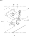
- FIG. 1 illustrates the conventional method of sensing a temperature by coupling a temperature sensor to a bus bar, like in a cantilever structure.
- a bus bar 20 is first coupled to a heating surface 10 of the PRA using a bus bar coupling bolt 30, and next a temperature sensor mounting ring 50 included in the temperature sensor 40 is loaded on the bus bar 20 and then coupled to the bus bar 20 using a temperature sensor mounting bolt 35.
- a nut (not shown) is attached to a corresponding position of the bus bar 20 through a clinching method to couple the temperature sensor mounting bolt 35 to the bus bar 20.
- the temperature sensor basically measures a temperature on a sensing surface 45 of its bottom, but since in the PRA the heat is actually generated at positions other than a position corresponding the sensing surface 45, a response rate in temperature measurement is decreased, and the measured value is read lower than actual temperature.
- the pressure for tightening the temperature sensor mounting bolt 35 is to be applied; due to a reaction to the pressure, the temperature sensing surface 45 may be lifted up from a surface of the bus bar 20 (see an arrow in FIG. 1 ). As a result, reliability and response rate of a measured value are lowered, and quality control of a product becomes quite difficult.
- a temperature sensor installing device for a power relay assembly which is configured to be attached to a lower surface of a bus bar attached to a heating surface of the power relay assembly, includes: a body housing; a temperature sensor insertion recess formed in an upper portion of the body housing and accommodating a temperature sensor such that a temperature sensing surface of the temperature sensor faces upward; and a nut insertion recess formed in the upper portion of the body housing and accommodating a nut.
- the nut may be inserted into the nut insertion recess of the body housing through any one of a press fitting, an insert molding, and a bonding.
- At least a portion of the body housing may be formed as a hollow chambered structure.
- a depth of the temperature sensor insertion recess of the body housing may be less than a height of the temperature sensor such that, when the temperature sensor is disposed in the temperature sensor insertion recess, the temperature sensing surface of the temperature sensor protrudes upward from a level of an upper surface of the body housing.
- a depth of the nut insertion recess of the body housing may be less than a height of the nut such that, when the nut is disposed in the nut insertion recess, a surface of the nut protrudes upward from a level of an upper surface of the body housing.
- a method for installing a temperature sensor on a heating surface of a power relay assembly includes: attaching a bus bar to the heating surface of the power relay assembly; bringing a temperature sensing surface of the temperature sensor into contact with a lower surface of the bus bar; and fixedly coupling the temperature sensor, with the temperature sensing surface being in contact with the lower surface of the bus bar, to the bus bar using a bolt.
- the bringing of the temperature sensing surface of the temperature sensor into contact with the lower surface of the bus bar and the fixedly coupling of the temperature sensor to the bus bar using the bolt may be performed by a temperature sensor installing device including: a body housing; a temperature sensor insertion recess formed in an upper portion of the body housing and accommodating the temperature sensor such that the temperature sensing surface faces upward; and a nut insertion recess formed in the upper portion of the body housing and accommodating a nut.
- the nut may be inserted into the nut insertion recess through any one of a press fitting method, an insert method, and a bonding method.
- At least a portion of the body housing may be formed as a hollow chambered structure.
- a power relay assembly in which a temperature sensor is installed includes: a bus bar attached to a heating surface of the power relay assembly; a temperature sensor installing device attached to a lower surface of the bus bar; and a temperature sensor disposed in the temperature sensor installing device and in contact with the lower surface of the bus bar.
- the temperature sensor is disposed in the temperature sensor installing device such that a temperature sensing surface of the temperature sensor faces upward.
- the bus bar is attached to the heating surface of the power relay assembly by a temperature sensor mounting bolt coupled to a nut of the temperature sensor installing device.
- the temperature sensor installing device may include: a body housing; a temperature sensor insertion recess formed in an upper portion of the body housing and accommodating the temperature sensor such that the temperature sensing surface faces upward; and a nut insertion recess formed in the upper portion of the body housing, and accommodating the nut.
- the nut may be inserted into the nut insertion recess of the body housing through any one of a press fitting, an insert molding, and a bonding.
- At least a portion of the body housing of the temperature sensor installing device may be formed as a hollow chambered structure.
- a shape of a lower end of the nut may correspond to a shape of the nut insertion recess.
- the nut insertion recess and a lower end of the nut may each have a tetragonal shape.
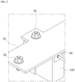
- FIG. 2 is a conceptual view of the present invention and illustrates a state in which a temperature sensor 40 is mounted on a lower surface of a bus bar 20 using a temperature sensor installing device 100 for a power relay assembly (PRA).
- PRA power relay assembly
- the temperature sensor installing device 100 in which the temperature sensor 40 is inserted is mounted on the lower surface of the bus bar 20, which is coupled to the PRA with a bus bar coupling bolt 30, using a temperature sensor mounting bolt 35.
- a nut (to be described below), to which the temperature sensor mounting bolt 35 is coupled, is inserted into the temperature sensor installing device 100 through an insert mold method, unlike the related art, and so the nut does not need to be clinched into the bus bar 20.
- FIG. 3 is a view of a state before the temperature sensor installing device 100 is installed on the bus bar 20 and a view for describing a relationship between the temperature sensor 40 and the temperature sensor installing device 100 mounted beneath the bus bar 20.
- the temperature sensor 40 is inserted into a space formed in an upper portion of a body housing of the temperature sensor installing device 100 such that a sensing surface 45 thereof faces upward.
- the temperature sensor installing device 100 is placed on the lower surface of the bus bar 20, and the temperature sensor mounting bolt 35 is coupled to a nut 60 disposed on the body housing.
- FIG. 4 is an exploded view of a temperature sensor installing device 100 according to an embodiment implementing a concept shown in FIGS. 2 and 3 .
- FIG. 5 illustrates a state in which a temperature sensor is assembled to the temperature sensor installing device 100 and then mounted on a bus bar 20 using a temperature sensor mounting bolt 35.
- the temperature sensor installing device 100 includes body housing 110a and 110b having an approximately rectangular shape. Although the temperature sensor installing device 100 includes a wider body housing portion 110a and a narrower body housing portion 110b, the present invention is not limited thereto, and of course, an entire body of the temperature sensor installing device 100 may be formed as one integral body housing.
- a temperature sensor insertion recess 120 is formed in an upper portion of the body housing 110b in an intaglio shape corresponding to a shape of a temperature sensor 40.
- the temperature sensor 40 is inserted into the temperature sensor insertion recess 120 in an inverted state such that a temperature sensing surface 45 thereof faces upward.
- a nut insertion recess 130 in which a nut 60 is placed (inserted or buried) is formed in an upper portion of the other body housing portion 110a.
- the nut 60 is hardware coupled to the temperature sensor mounting bolt 35.
- FIG. 4 illustrates that the nut insertion recess 130 has a tetragonal shape and a lower end of the nut 60 also has a tetragonal shape corresponding thereto.
- a method of attaching the nut 60 to the nut insertion recess 130 a method such as a press fitting, bonding, insert molding, insert injection, etc. may be used.
- the nut 60 may be press-fitted into or bonded to the nut insertion recess 130.
- the nut 60 may be integrally formed through a method such as an insert molding or insert injection method.
- the entirety portions of or at least a portion of the body housing 110a and 110b is formed as a hollow chambered structure. As a result, it is possible to minimize the heat transfer to the body housing from a heat generating portion of a PRA (a portion of which a temperature is to be measured with the temperature sensor), thereby accurately transferring heat generated from the PRA to the temperature sensor.
- the temperature sensor installing device 100 in which the nut 60 is inserted into the body housing portion 110a and the temperature sensor 40 is inserted into the temperature sensor insertion recess 120 of the body housing portion 110b such that the sensing surface 45 thereof faces upward, is placed on a lower surface of the bus bar 20, and the temperature sensor mounting bolt 35 is coupled to the nut 60 from above to install the temperature sensor 40. Due to such a temperature sensor installation structure, an exposed area of the temperature sensor other than the bus bar is minimized.
- the nut 60 to which the temperature sensor mounting bolt 35 is coupled can be press-fitted, bonded, or inserted into the body housing 110a, and thus an effect can be expected of reducing costs as compared with a conventional method of attaching the nut 60 to the bus bar 20 using a clinching method.
- a depth of the temperature sensor insertion recess 120 is made smaller than a height of the temperature sensor 40, and thus, the sensing surface 45 is designed to protrude upward by a height h from an upper surface height of the body housing 110b after the temperature sensor 40 is inserted. Accordingly, the nut 60 is also inserted so as to protrude upward by approximately the height h from an upper surface height of the body housing 110a.
- the amount of height h is an arbitrary value, but according to one embodiment, the height h is about 2 mm.
Landscapes
- Engineering & Computer Science (AREA)
- Physics & Mathematics (AREA)
- General Physics & Mathematics (AREA)
- Power Engineering (AREA)
- Manufacturing & Machinery (AREA)
- General Chemical & Material Sciences (AREA)
- Chemical Kinetics & Catalysis (AREA)
- Electrochemistry (AREA)
- Chemical & Material Sciences (AREA)
- Life Sciences & Earth Sciences (AREA)
- Sustainable Development (AREA)
- Sustainable Energy (AREA)
- Transportation (AREA)
- Mechanical Engineering (AREA)
- Microelectronics & Electronic Packaging (AREA)
- Measuring Temperature Or Quantity Of Heat (AREA)
Applications Claiming Priority (1)
| Application Number | Priority Date | Filing Date | Title |
|---|---|---|---|
| KR1020200090553A KR20220011860A (ko) | 2020-07-21 | 2020-07-21 | 온도센싱 신뢰도를 높인 파워릴레이 어셈블리 및 이에 사용되는 온도센서 설치 장치 및 방법 |
Publications (1)
| Publication Number | Publication Date |
|---|---|
| EP3943902A1 true EP3943902A1 (de) | 2022-01-26 |
Family
ID=77021137
Family Applications (1)
| Application Number | Title | Priority Date | Filing Date |
|---|---|---|---|
| EP21186933.4A Pending EP3943902A1 (de) | 2020-07-21 | 2021-07-21 | Temperatursensorinstallationsvorrichtung für leistungsrelaisanordnung und temperatursensorinstallationsverfahren für leistungsrelaisanordnung |
Country Status (4)
| Country | Link |
|---|---|
| US (1) | US11506543B2 (de) |
| EP (1) | EP3943902A1 (de) |
| KR (1) | KR20220011860A (de) |
| CN (1) | CN215909997U (de) |
Citations (2)
| Publication number | Priority date | Publication date | Assignee | Title |
|---|---|---|---|---|
| US20060165153A1 (en) * | 2005-01-21 | 2006-07-27 | Eaton Corporation | Apparatus and method for detecting hot spots in an electric power conductor |
| WO2019169894A1 (en) * | 2018-03-09 | 2019-09-12 | Abb Schweiz Ag | Device for measuring temperature of conductor |
Family Cites Families (1)
| Publication number | Priority date | Publication date | Assignee | Title |
|---|---|---|---|---|
| JPH0464025A (ja) * | 1990-07-02 | 1992-02-28 | Matsushita Electric Ind Co Ltd | 調理器用温度センサー |
-
2020
- 2020-07-21 KR KR1020200090553A patent/KR20220011860A/ko active Pending
-
2021
- 2021-07-21 US US17/381,607 patent/US11506543B2/en active Active
- 2021-07-21 CN CN202121661027.7U patent/CN215909997U/zh active Active
- 2021-07-21 EP EP21186933.4A patent/EP3943902A1/de active Pending
Patent Citations (2)
| Publication number | Priority date | Publication date | Assignee | Title |
|---|---|---|---|---|
| US20060165153A1 (en) * | 2005-01-21 | 2006-07-27 | Eaton Corporation | Apparatus and method for detecting hot spots in an electric power conductor |
| WO2019169894A1 (en) * | 2018-03-09 | 2019-09-12 | Abb Schweiz Ag | Device for measuring temperature of conductor |
Also Published As
| Publication number | Publication date |
|---|---|
| US11506543B2 (en) | 2022-11-22 |
| CN215909997U (zh) | 2022-02-25 |
| KR20220011860A (ko) | 2022-02-03 |
| US20220026282A1 (en) | 2022-01-27 |
Similar Documents
| Publication | Publication Date | Title |
|---|---|---|
| US10153598B2 (en) | Terminal and charging connector with temperature measurement | |
| US7488904B2 (en) | Resin molded component fitted with a metal plate and molding method therefor | |
| KR101658073B1 (ko) | 온도 센서, 온도 센서 제조 방법 및 대응하는 온도 센서 조립 방법 | |
| US20080017174A1 (en) | Electronic Control Unit for Motor Vehicle Braking Systems | |
| JP6192324B2 (ja) | 電子制御装置 | |
| CN104160284A (zh) | 用于固定在汇流排上的电流传感器 | |
| WO2017221464A1 (ja) | 温度検出装置 | |
| CN214821768U (zh) | 烫印机 | |
| US11506543B2 (en) | Temperature sensor installing device and method for power relay assembly | |
| US7033074B2 (en) | Temperature-sensor fixing holder | |
| CN204439654U (zh) | 车轮转速传感器 | |
| CN111157129B (zh) | 温度测量装置及所应用的电线圈组件 | |
| CN211740541U (zh) | 一种底座及振动测试装置 | |
| JP2005347152A (ja) | バッテリ温度測定装置 | |
| CN116972915A (zh) | 一体式压力温度变送器 | |
| JP2000337988A (ja) | 圧力検出装置 | |
| CN220853925U (zh) | 一种温度传感器 | |
| CN107933393B (zh) | 汽车座椅控制系统及汽车座椅总装 | |
| CN205991652U (zh) | 一种冰箱蒸发器d型感温套管组件 | |
| JP3027157B1 (ja) | センサ | |
| CN217994153U (zh) | 一种工程车辆油门踏板 | |
| CN216288604U (zh) | 温度采集装置 | |
| CN223666601U (zh) | 安装件、电容模块、电机控制器、动力总成和车辆 | |
| CN211347125U (zh) | 开关组件和电机控制器 | |
| CN223463137U (zh) | 一种加热装置 |
Legal Events
| Date | Code | Title | Description |
|---|---|---|---|
| PUAI | Public reference made under article 153(3) epc to a published international application that has entered the european phase |
Free format text: ORIGINAL CODE: 0009012 |
|
| STAA | Information on the status of an ep patent application or granted ep patent |
Free format text: STATUS: REQUEST FOR EXAMINATION WAS MADE |
|
| 17P | Request for examination filed |
Effective date: 20210721 |
|
| AK | Designated contracting states |
Kind code of ref document: A1 Designated state(s): AL AT BE BG CH CY CZ DE DK EE ES FI FR GB GR HR HU IE IS IT LI LT LU LV MC MK MT NL NO PL PT RO RS SE SI SK SM TR |
|
| RBV | Designated contracting states (corrected) |
Designated state(s): AL AT BE BG CH CY CZ DE DK EE ES FI FR GB GR HR HU IE IS IT LI LT LU LV MC MK MT NL NO PL PT RO RS SE SI SK SM TR |