EP3943789A1 - Safety cap - Google Patents
Safety cap Download PDFInfo
- Publication number
- EP3943789A1 EP3943789A1 EP21173465.2A EP21173465A EP3943789A1 EP 3943789 A1 EP3943789 A1 EP 3943789A1 EP 21173465 A EP21173465 A EP 21173465A EP 3943789 A1 EP3943789 A1 EP 3943789A1
- Authority
- EP
- European Patent Office
- Prior art keywords
- sealing member
- reservoir
- sealing
- valve
- safety cap
- Prior art date
- Legal status (The legal status is an assumption and is not a legal conclusion. Google has not performed a legal analysis and makes no representation as to the accuracy of the status listed.)
- Pending
Links
Images

Classifications
-
- F—MECHANICAL ENGINEERING; LIGHTING; HEATING; WEAPONS; BLASTING
- F01—MACHINES OR ENGINES IN GENERAL; ENGINE PLANTS IN GENERAL; STEAM ENGINES
- F01P—COOLING OF MACHINES OR ENGINES IN GENERAL; COOLING OF INTERNAL-COMBUSTION ENGINES
- F01P11/00—Component parts, details, or accessories not provided for in, or of interest apart from, groups F01P1/00 - F01P9/00
- F01P11/02—Liquid-coolant filling, overflow, venting, or draining devices
- F01P11/0204—Filling
- F01P11/0209—Closure caps
- F01P11/0238—Closure caps with overpressure valves or vent valves
-
- F—MECHANICAL ENGINEERING; LIGHTING; HEATING; WEAPONS; BLASTING
- F16—ENGINEERING ELEMENTS AND UNITS; GENERAL MEASURES FOR PRODUCING AND MAINTAINING EFFECTIVE FUNCTIONING OF MACHINES OR INSTALLATIONS; THERMAL INSULATION IN GENERAL
- F16K—VALVES; TAPS; COCKS; ACTUATING-FLOATS; DEVICES FOR VENTING OR AERATING
- F16K15/00—Check valves
- F16K15/14—Check valves with flexible valve members
- F16K15/148—Check valves with flexible valve members the closure elements being fixed in their centre
Definitions
- the present invention relates to a safety cap, for example for use on an expansion tank or radiator of an automobile.
- Safety caps are often used to regulate pressure within reservoirs - for example expansion tanks or radiators used as part of cooling circuits in an automobile.
- safety caps of this type generally comprise a body in which is disposed a valve held at the bottom of said body by means of a spring.
- the upper end of said spring abuts against a fixed element to thereby allow the valve to move vertically during an internal overpressure, until the internal pressure returns to normal.
- a further valve containing a further spring which deforms during a depression in the tank, making it possible to restore the lack of pressure.
- the opening generated by the movement of the valve is achieved by the elasticity of the springs which compress as soon as the pressure in the circuit arrives at the critical conditions imposed by the manufacturer.
- a known safety cap is illustrated in Figure 1 .
- a safety cap for a fluid reservoir said safety cap being configured to be attached to a neck of said reservoir, said safety cap comprising:
- the first sealing member comprises a flexible gasket element.
- the first sealing member comprises an annular gasket element which surrounds the flexible sealing member.
- the flexible sealing member comprises an umbrella valve.
- the umbrella valve comprises a stem and a canopy portion, the stem of the umbrella valve extending upwardly into the sealing member housing.
- the sealing member housing includes two passages extending therethrough and wherein the canopy portion of the valve extends over the passages.
- the canopy portion of the valve is biased towards the passages.
- the invention also relates to an assembly comprising: a fluid reservoir having a neck portion; and a safety cap according to the invention.
- a safety cap for a fluid reservoir said safety cap being configured to be attached to a neck of said reservoir, said safety cap comprising:
- the flexible sealing member comprises a flexible gasket element.
- the at least one opening comprises a slit.
- the flexible sealing member comprises a radially outer portion and a radially inner portion, wherein the at least one opening is positioned between the radially outer portion and the radially inner portion.
- the openings are arc shaped or substantially circular sectors.
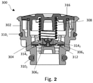
- Figure 2 illustrate examples of safety caps for a fluid reservoir.
- the reservoir may be, for example, an expansion tank or radiator of an automobile.
- the reservoir may be, for example, part of a cooling circuit for an automobile.
- the safety cap is configured to be attached or fixed to a neck of the reservoir.
- Figure 2 illustrate an example of a safety cap 300.
- the safety cap 100 includes a safety valve.
- the safety valve includes a valve body 302, configured to be in sealing arrangement with a neck of reservoir.
- annular sealing elements 310 1,2 are provided around the valve body 302 to provide a seal between the safety cap 300 and the neck of the reservoir (not shown).
- valve body 302 includes a seat portion 312.
- seat portion 312 is a raised annular portion, or ridge, located within an interior of the valve body 302.
- the safety valve further includes a sealing arrangement located within an interior of the valve body 302.
- the sealing arrangement includes a sealing member housing 304.
- the sealing member housing 304 includes a recessed portion configured to receive a sealing member.
- the sealing member housing 304 includes at least one passage extending therethrough.
- the sealing member housing 304 includes two passages 314 1,2 extending therethrough.
- the sealing member may comprise only one passage. It may also comprise any number of passages. That is, the passages 314 1,2 extends from a first side of the sealing member housing 304 (for example an upper side) to a second side of the sealing member housing 304 (for example a lower side).
- the sealing arrangement further includes a flexible sealing member 306 2 .
- the sealing arrangement further includes a first sealing member 306 1 which is for instance a flexible gasket element.
- the flexible gasket element is for instance a thin annular gasket element which surrounds the flexible sealing member. Such gasket is for instance configured to be received within the recessed portion the sealing member housing 304.
- the flexible sealing member 306 2 and the first sealing member forms at least one opening extending therethrough.
- the safety valve is configured to regulate the pressure within the reservoir.
- the safety valve is configured to help address over- or under-pressure situations within the reservoir.
- Figure 2 illustrates the safety valve in an equilibrium position. That is, Figure 2 illustrates the safety valve when the pressure within the reservoir is at an acceptable level where regulation is not required.
- the sealing arrangement is in a sealing configuration. In general, in the sealing configuration the sealing arrangement prevents fluid passing from the reservoir, through the interior of the valve body 302 to the environment (and likewise from the environment into the reservoir).
- a surface of the flexible sealing member 306 2 engages with and forms a seal against a corresponding surface of the sealing member housing 104 to seal the passages 314 1,2 .
- an upper surface of the flexible sealing member 306 2 abuts a lower surface of the sealing member housing 304.
- the passages 314 1,2 of the sealing member housing 304 are covered by the upper surface of the flexible sealing member 306 2 . As such passage of fluid through the passages 314 1,2 are blocked.
- the safety valve further includes a biasing element 308 configured to bias the sealing arrangement into a sealing engagement with a portion of the valve body 302.
- the biasing element 308 biases the sealing arrangement downwardly towards the seat portion 312.
- the first sealing member 306 1 engages with and forms a seal against the seat portion 312.
- the biasing element 308 is a spring.
- the spring 308 pushes against frame element 316, which itself is fixed with respect to the valve body 302.
- the seat portion 312 is positioned so as to engage with a radially outer portion of the first sealing member 306 1 .
- the engagement between the first sealing member 306 1 prevents passage of fluid around the sealing arrangement (that is, between a side of the sealing arrangement and the surrounding interior surface of the valve body 302).
- the safety valve is configured such that when the reservoir becomes over-pressurised (that is, the pressure in the reservoir rises above an upper threshold value), the sealing arrangement pushes against the biasing element (spring) 308 to move out of sealing engagement with the valve body 302 (the sealing arrangement compresses the spring 308 and moves out of sealing engagement with the valve body 302).
- the sealing arrangement moves away from the seat portion 312 to allow the passage of fluid from the reservoir around the sealing arrangement.
- the fluid can subsequently be vented so as to reduce the pressure within the reservoir.
- the sealing arrangement pushes against the spring 308 to allow venting until the internal pressure returns to an acceptable level (i.e. below the upper threshold value).
- the flexible sealing member 306 2 deforms away from the corresponding surface of the sealing member housing 304, breaking the seal therebetween and creating a flow path into the reservoir through the at least one passage in the sealing member housing 304. It allows fluid to pass into the reservoir through the passages 314 1,2 in the sealing member housing 304.
- the canopy of the flexible sealing member 306 2 flexes away from the lower surface of the sealing member housing 304. This creates a gap therebetween, or more particularly a flow path from the passages 314 1,2 to the reservoir. As such, the pressure in the reservoir can be raised. The flexible sealing member 306 2 remains is deformed until the internal pressure returns to an acceptable level.
- the sealing arrangement includes two sealing members - a first sealing member 306 1 and a flexible sealing member 306 2 .
- the first sealing member 306 1 includes an annular gasket element.
- the flexible sealing member 306 2 is an umbrella valve.
- the first sealing member 306 1 surrounds the umbrella valve 306 2 .
- the biasing element 308 biases the first sealing member 306 1 into sealing engagement with the seat portion 312.
- the sealing member housing includes two passages 314 1,2 extending therethrough.
- a surface of the umbrella valve 306 2 engages with and forms a seal against a corresponding surface of the sealing member housing 304 to seal the passages 314 1,2 .
- the stem of the umbrella valve extends upwardly into the sealing member housing 304, with the canopy portion of the valve extending over the passages 314 1,2 .
- the canopy portion of the valve is biased towards the passages 314 1,2 .
- the safety cap 300 works in the same manner as previous examples during an overpressure situation.
- the canopy portion of the umbrella valve 306 2 deforms away from the corresponding surface of the sealing member housing 304, breaking the seal therebetween and allowing fluid to pass into the reservoir through the passages 314 1,2 in the sealing member housing.
- deformation of the canopy portion of the umbrella valve 306 2 creates a gap between the umbrella valve 306 2 and the first sealing member 306 1 that forms opening between the first sealing member 306 1 and the umbrella valve 306 2 . That is a flow path is created between the first sealing member 306 1 and the umbrella valve 306 2 .
- a seal is created between surfaces of the sealing member and the sealing member housing.
- the contact between these surfaces covers a substantial amount of said surfaces helping ensure a tight seal.
- the fluid passage from the environment into the reservoir is created through the deformation of the flexible sealing member as a whole (rather than relative deformation within the flexible sealing member itself, for example a flap portion in the flexible sealing member).
Landscapes
- Engineering & Computer Science (AREA)
- General Engineering & Computer Science (AREA)
- Mechanical Engineering (AREA)
- Chemical & Material Sciences (AREA)
- Combustion & Propulsion (AREA)
- Closures For Containers (AREA)
Abstract
Description
- The present invention relates to a safety cap, for example for use on an expansion tank or radiator of an automobile.
- Safety caps are often used to regulate pressure within reservoirs - for example expansion tanks or radiators used as part of cooling circuits in an automobile.
- It is known that safety caps of this type generally comprise a body in which is disposed a valve held at the bottom of said body by means of a spring. The upper end of said spring abuts against a fixed element to thereby allow the valve to move vertically during an internal overpressure, until the internal pressure returns to normal. In the body of the valve is disposed a further valve containing a further spring which deforms during a depression in the tank, making it possible to restore the lack of pressure. The opening generated by the movement of the valve is achieved by the elasticity of the springs which compress as soon as the pressure in the circuit arrives at the critical conditions imposed by the manufacturer. A known safety cap is illustrated in
Figure 1 . - These safety plugs therefore make it possible, during a depression or an overpressure, to bring the cooling circuit down to the operating pressure prescribed by the manufacturer. Currently, safety conditions are around 1.4 bar + 15%, that is to say that the safety valve only becomes operational for pressures below or above these limits.
- Known systems can be complicated and expensive. It is an aim of the present invention to provide a safety cap with reduced complexity without compromising on performance and reliability.
- According to a first aspect of the present invention there is provided a safety cap for a fluid reservoir, said safety cap being configured to be attached to a neck of said reservoir, said safety cap comprising:
- a safety valve configured to regulate the pressure within the reservoir, the safety valve comprising:
- a valve body, configured to be in sealing arrangement with the neck of the reservoir;
- a sealing arrangement, comprising:
- a sealing member housing having at least one passage extending therethrough;
- a first sealing member;
- a flexible sealing member, wherein in a sealing configuration a surface of the flexible sealing member engages with and forms a seal against a corresponding surface of the sealing member housing to seal the at least one passage;
- a biasing element configured to bias the sealing arrangement into a sealing engagement with a portion of the valve body;
- wherein, the safety valve is configured such that when the pressure in the reservoir is above an upper threshold value, the sealing arrangement pushes against the biasing element to move out of sealing engagement with the valve body;
- wherein, the safety valve is configured such that when the pressure in the reservoir is below a lower threshold, the flexible sealing member deforms away from the corresponding surface of the sealing member housing, breaking the seal therebetween and creating a flow path into the reservoir through the at least one passage in the sealing member housing.
- According to an aspect of the invention, the first sealing member comprises a flexible gasket element.
- According to an aspect of the invention, the first sealing member comprises an annular gasket element which surrounds the flexible sealing member.
- According to an aspect of the invention, the flexible sealing member comprises an umbrella valve.
- According to an aspect of the invention, the umbrella valve comprises a stem and a canopy portion, the stem of the umbrella valve extending upwardly into the sealing member housing.
- According to an aspect of the invention, the sealing member housing includes two passages extending therethrough and wherein the canopy portion of the valve extends over the passages.
- According to an aspect of the invention, the canopy portion of the valve is biased towards the passages.
- The invention also relates to an assembly comprising:
a fluid reservoir having a neck portion; and
a safety cap according to the invention. - According to a second example of the invention, there is provided a safety cap for a fluid reservoir, said safety cap being configured to be attached to a neck of said reservoir, said safety cap comprising:
- a safety valve configured to regulate the pressure within the reservoir, the safety valve comprising:
- a valve body, configured to be in sealing arrangement with the neck of the reservoir;
- a sealing arrangement, comprising:
- a sealing member housing having at least one passage extending therethrough; and
- a flexible sealing member, comprising at least one opening extending therethrough, wherein in a sealing configuration a surface of the flexible sealing member engages with and forms a seal against a corresponding surface of the sealing member housing to seal the at least one passage and the at least one opening;
- a biasing element configured to bias the sealing arrangement into a sealing engagement with a portion of the valve body;
- wherein, the safety valve is configured such that when the pressure in the reservoir is above an upper threshold value, the sealing arrangement pushes against the biasing element to move out of sealing engagement with the valve body;
- wherein, the safety valve is configured such that when the pressure in the reservoir is below a lower threshold, the flexible sealing member deforms away from the corresponding surface of the sealing member housing, breaking the seal therebetween and creating a flow path into the reservoir through the at least one passage in the sealing member housing and the at least one opening in the sealing member.
- Aptly, the flexible sealing member comprises a flexible gasket element.
- Aptly the at least one opening comprises a slit.
- According to an aspect of the invention, the flexible sealing member comprises a radially outer portion and a radially inner portion, wherein the at least one opening is positioned between the radially outer portion and the radially inner portion.
- According to an aspect of the invention, three openings defined between three connecting portions.
- According to an aspect of the invention, the openings are arc shaped or substantially circular sectors.
- Examples of the present invention will now be described hereinafter, by way of example only, with reference to the accompanying drawings in which:
-
Figure 1 illustrates a side cross-sectional view of a known safety cap; -
Figure 2 illustrates a side cross-sectional view of an example of a safety cap - In the drawings like reference numerals refer to like parts.
-
Figure 2 illustrate examples of safety caps for a fluid reservoir. The reservoir may be, for example, an expansion tank or radiator of an automobile. The reservoir may be, for example, part of a cooling circuit for an automobile. In general, the safety cap is configured to be attached or fixed to a neck of the reservoir. -
Figure 2 illustrate an example of asafety cap 300. The safety cap 100 includes a safety valve. - The safety valve includes a
valve body 302, configured to be in sealing arrangement with a neck of reservoir. In this example, annular sealing elements 3101,2 are provided around thevalve body 302 to provide a seal between thesafety cap 300 and the neck of the reservoir (not shown). - In this example, the
valve body 302 includes aseat portion 312. In this example theseat portion 312 is a raised annular portion, or ridge, located within an interior of thevalve body 302. - The safety valve further includes a sealing arrangement located within an interior of the
valve body 302. The sealing arrangement includes a sealingmember housing 304. The sealingmember housing 304 includes a recessed portion configured to receive a sealing member. - The sealing
member housing 304 includes at least one passage extending therethrough. In this example the sealingmember housing 304 includes two passages 3141,2 extending therethrough. Of course, according to other aspects of the invention, the sealing member may comprise only one passage. It may also comprise any number of passages. That is, the passages 3141,2 extends from a first side of the sealing member housing 304 (for example an upper side) to a second side of the sealing member housing 304 (for example a lower side). - In this example, the sealing arrangement further includes a flexible sealing member 3062. In this example, the sealing arrangement further includes a first sealing member 3061 which is for instance a flexible gasket element. The flexible gasket element is for instance a thin annular gasket element which surrounds the flexible sealing member. Such gasket is for instance configured to be received within the recessed portion the sealing
member housing 304. - The flexible sealing member 3062 and the first sealing member forms at least one opening extending therethrough.
- The safety valve is configured to regulate the pressure within the reservoir. In particular, the safety valve is configured to help address over- or under-pressure situations within the reservoir.
-
Figure 2 illustrates the safety valve in an equilibrium position. That is,Figure 2 illustrates the safety valve when the pressure within the reservoir is at an acceptable level where regulation is not required. When the safety valve is in the equilibrium position, the sealing arrangement is in a sealing configuration. In general, in the sealing configuration the sealing arrangement prevents fluid passing from the reservoir, through the interior of thevalve body 302 to the environment (and likewise from the environment into the reservoir). - In the sealing configuration a surface of the flexible sealing member 3062 engages with and forms a seal against a corresponding surface of the sealing member housing 104 to seal the passages 3141,2.
- In the illustrated example, an upper surface of the flexible sealing member 3062 abuts a lower surface of the sealing
member housing 304. The passages 3141,2 of the sealingmember housing 304 are covered by the upper surface of the flexible sealing member 3062. As such passage of fluid through the passages 3141,2 are blocked. - The safety valve further includes a biasing
element 308 configured to bias the sealing arrangement into a sealing engagement with a portion of thevalve body 302. In this example, the biasingelement 308 biases the sealing arrangement downwardly towards theseat portion 312. As such, the first sealing member 3061 engages with and forms a seal against theseat portion 312. - In this example the biasing
element 308 is a spring. In this example, thespring 308 pushes againstframe element 316, which itself is fixed with respect to thevalve body 302. - In this example the
seat portion 312 is positioned so as to engage with a radially outer portion of the first sealing member 3061. The engagement between the first sealing member 3061 prevents passage of fluid around the sealing arrangement (that is, between a side of the sealing arrangement and the surrounding interior surface of the valve body 302). - The safety valve is configured such that when the reservoir becomes over-pressurised (that is, the pressure in the reservoir rises above an upper threshold value), the sealing arrangement pushes against the biasing element (spring) 308 to move out of sealing engagement with the valve body 302 (the sealing arrangement compresses the
spring 308 and moves out of sealing engagement with the valve body 302). - In this example the sealing arrangement moves away from the
seat portion 312 to allow the passage of fluid from the reservoir around the sealing arrangement. The fluid can subsequently be vented so as to reduce the pressure within the reservoir. The sealing arrangement pushes against thespring 308 to allow venting until the internal pressure returns to an acceptable level (i.e. below the upper threshold value). - Conversely, if the reservoir becomes de-pressurised or suffers a depression event (that is, the pressure in the reservoir falls below a lower threshold value), the flexible sealing member 3062 deforms away from the corresponding surface of the sealing
member housing 304, breaking the seal therebetween and creating a flow path into the reservoir through the at least one passage in the sealingmember housing 304. It allows fluid to pass into the reservoir through the passages 3141,2 in the sealingmember housing 304. - Put another way, the canopy of the flexible sealing member 3062 flexes away from the lower surface of the sealing
member housing 304. This creates a gap therebetween, or more particularly a flow path from the passages 3141,2 to the reservoir. As such, the pressure in the reservoir can be raised. The flexible sealing member 3062 remains is deformed until the internal pressure returns to an acceptable level. - In this example the sealing arrangement includes two sealing members - a first sealing member 3061 and a flexible sealing member 3062. In this example, the first sealing member 3061 includes an annular gasket element. The flexible sealing member 3062 is an umbrella valve. The first sealing member 3061 surrounds the umbrella valve 3062. In this example the biasing
element 308 biases the first sealing member 3061 into sealing engagement with theseat portion 312. - In this example, the sealing member housing includes two passages 3141,2 extending therethrough. As with the previous examples, in a sealing configuration a surface of the umbrella valve 3062 engages with and forms a seal against a corresponding surface of the sealing
member housing 304 to seal the passages 3141,2. In this example, the stem of the umbrella valve extends upwardly into the sealingmember housing 304, with the canopy portion of the valve extending over the passages 3141,2. The canopy portion of the valve is biased towards the passages 3141,2. - The
safety cap 300 works in the same manner as previous examples during an overpressure situation. In a depression situation, the canopy portion of the umbrella valve 3062 deforms away from the corresponding surface of the sealingmember housing 304, breaking the seal therebetween and allowing fluid to pass into the reservoir through the passages 3141,2 in the sealing member housing. In effect, deformation of the canopy portion of the umbrella valve 3062 creates a gap between the umbrella valve 3062 and the first sealing member 3061 that forms opening between the first sealing member 3061 and the umbrella valve 3062. That is a flow path is created between the first sealing member 3061 and the umbrella valve 3062. - In the described examples, a seal is created between surfaces of the sealing member and the sealing member housing. The contact between these surfaces covers a substantial amount of said surfaces helping ensure a tight seal.
- In addition, the fluid passage from the environment into the reservoir (in the event of a depressurisation event) is created through the deformation of the flexible sealing member as a whole (rather than relative deformation within the flexible sealing member itself, for example a flap portion in the flexible sealing member). This creates a more reliable seal that is less likely to degrade over time. That is, the at least one opening is always present in the flexible sealing member, but is covered and sealed through contact with the sealing member housing when the pressure within in the reservoir is acceptable.
- It will be clear to a person skilled in the art that features described in relation to any of the embodiments described above can be applicable interchangeably between the different embodiments.
- Throughout the description and claims of this specification, the words "comprise" and "contain" and variations of them mean "including but not limited to", and they are not intended to (and do not) exclude other moieties, additives, components, integers or steps. Throughout the description and claims of this specification, the singular encompasses the plural unless the context otherwise requires. In particular, where the indefinite article is used, the specification is to be understood as contemplating plurality as well as singularity, unless the context requires otherwise.
- Features, integers, characteristics, compounds, chemical moieties or groups described in conjunction with a particular aspect, embodiment or example of the invention are to be understood to be applicable to any other aspect, embodiment or example described herein unless incompatible therewith. All of the features disclosed in this specification (including any accompanying claims, abstract and drawings), and/or all of the steps of any method or process so disclosed, may be combined in any combination, except combinations where at least some of such features and/or steps are mutually exclusive. The invention is not restricted to the details of any foregoing embodiments. The invention extends to any novel one, or any novel combination, of the features disclosed in this specification (including any accompanying claims, abstract and drawings), or to any novel one, or any novel combination, of the steps of any method or process so disclosed.
Claims (8)
- A safety cap (300) for a fluid reservoir, said safety cap (300) being configured to be attached to a neck of said reservoir, said safety cap (300) comprising:a safety valve configured to regulate the pressure within the reservoir, the safety valve comprising:a valve body (302), configured to be in sealing arrangement with the neck of the reservoir;a sealing arrangement, comprising:a sealing member housing (304) having at least one passage extending therethrough;a first sealing member (3061);a flexible sealing member (3062), wherein in a sealing configuration a surface of the flexible sealing member engages with and forms a seal against a corresponding surface of the sealing member housing to seal the at least one passage;a biasing element (308) configured to bias the sealing arrangement into a sealing engagement with a portion of the valve body;wherein, the safety valve is configured such that when the pressure in the reservoir is above an upper threshold value, the sealing arrangement pushes against the biasing element (308) to move out of sealing engagement with the valve body;wherein, the safety valve is configured such that when the pressure in the reservoir is below a lower threshold, the flexible sealing member (3062) deforms away from the corresponding surface of the sealing member housing (304), breaking the seal therebetween and creating a flow path into the reservoir through the at least one passage in the sealing member housing (304).
- A safety cap according to claim 1, wherein the first sealing member (3061) comprises a flexible gasket element.
- A safety cap according to any of claims 1 or 2, wherein the first sealing member (3061) comprises an annular gasket element which surrounds the flexible sealing member.
- A safety cap according to any of the preceding claims, wherein the flexible sealing member comprises an umbrella valve (3062).
- A safety cap according to claim 4, wherein the umbrella valve comprises a stem and a canopy portion, the stem of the umbrella valve extending upwardly into the sealing member housing (304)
- A safety cap according to claim 5, wherein the sealing member housing includes two passages (3141,2) extending therethrough and wherein the canopy portion of the valve extends over the passages (3141,2).
- A safety cap according to claim 6, wherein the canopy portion of the valve is biased towards the passages (3141,2).
- An assembly comprising:a fluid reservoir having a neck portion; anda safety cap according to any preceding claim.
Applications Claiming Priority (1)
| Application Number | Priority Date | Filing Date | Title |
|---|---|---|---|
| EP20186785 | 2020-07-20 |
Publications (1)
| Publication Number | Publication Date |
|---|---|
| EP3943789A1 true EP3943789A1 (en) | 2022-01-26 |
Family
ID=71950392
Family Applications (1)
| Application Number | Title | Priority Date | Filing Date |
|---|---|---|---|
| EP21173465.2A Pending EP3943789A1 (en) | 2020-07-20 | 2021-05-12 | Safety cap |
Country Status (1)
| Country | Link |
|---|---|
| EP (1) | EP3943789A1 (en) |
Citations (3)
| Publication number | Priority date | Publication date | Assignee | Title |
|---|---|---|---|---|
| US3929158A (en) * | 1974-07-03 | 1975-12-30 | Stant Mfg Co | Remote pressure-vacuum relief valve assembly |
| GB1534318A (en) * | 1976-08-12 | 1978-11-29 | Gen Motors France | Closure caps |
| WO2016056702A1 (en) * | 2014-10-10 | 2016-04-14 | 코스모이엔지(주) | Auxiliary coolant tank cap |
-
2021
- 2021-05-12 EP EP21173465.2A patent/EP3943789A1/en active Pending
Patent Citations (3)
| Publication number | Priority date | Publication date | Assignee | Title |
|---|---|---|---|---|
| US3929158A (en) * | 1974-07-03 | 1975-12-30 | Stant Mfg Co | Remote pressure-vacuum relief valve assembly |
| GB1534318A (en) * | 1976-08-12 | 1978-11-29 | Gen Motors France | Closure caps |
| WO2016056702A1 (en) * | 2014-10-10 | 2016-04-14 | 코스모이엔지(주) | Auxiliary coolant tank cap |
Similar Documents
| Publication | Publication Date | Title |
|---|---|---|
| US11792944B2 (en) | Valve for pressure compensation and/or for emergency venting of a container, in particular of a container of a battery of an electric vehicle, as well as container with such a valve | |
| KR100909454B1 (en) | On / off valve device for fluid | |
| US4079855A (en) | Monolithic radiator cap for sealed pressurized cooling system | |
| US6481592B2 (en) | Fuel tank vent valve | |
| US20110017734A1 (en) | Closure cover for tanks under internal pressure, with a safety function, and closure cover for a fuel tank | |
| US7163023B2 (en) | Fuel vapor vent valve float assembly and method of making same | |
| US10156294B2 (en) | Fluidic safety valve and battery component equipped therewith | |
| CN1229460A (en) | Bellows Elastomeric Seals | |
| JP2006266265A (en) | Low-contour overfill restricting device having reverse distribution performance | |
| US20100089467A1 (en) | Thermmostatic assembly for fluid flow adjustment, and method making for such assembly | |
| KR20150099391A (en) | Valve assembly for a tank of a vehicle | |
| US5153396A (en) | Combination high pressure switch and valve device | |
| CN109664750B (en) | Valve device for fuel tank | |
| US9683479B2 (en) | Safety cap device for controlling pressure in radiator and method for controlling pressure using the same | |
| US11339879B2 (en) | Seal assembly and fluid valve | |
| US20020092567A1 (en) | Pressure relief device with one piece gasket | |
| JP2010121637A (en) | Metal bellows accumulator | |
| KR101341992B1 (en) | Dual pressure adjustable no-load radiator valve | |
| US8684215B2 (en) | Fuel cap | |
| KR20100025398A (en) | A cap of radiator | |
| JP4006485B2 (en) | Tire air valve | |
| US7819129B2 (en) | Relief vent including float and seal | |
| EP0097443A1 (en) | Pressure cap | |
| JP3923382B2 (en) | Pressure regulator of pressure rice cooker | |
| CN115280042B (en) | Sealed structure |
Legal Events
| Date | Code | Title | Description |
|---|---|---|---|
| PUAI | Public reference made under article 153(3) epc to a published international application that has entered the european phase |
Free format text: ORIGINAL CODE: 0009012 |
|
| STAA | Information on the status of an ep patent application or granted ep patent |
Free format text: STATUS: THE APPLICATION HAS BEEN PUBLISHED |
|
| AK | Designated contracting states |
Kind code of ref document: A1 Designated state(s): AL AT BE BG CH CY CZ DE DK EE ES FI FR GB GR HR HU IE IS IT LI LT LU LV MC MK MT NL NO PL PT RO RS SE SI SK SM TR |
|
| STAA | Information on the status of an ep patent application or granted ep patent |
Free format text: STATUS: REQUEST FOR EXAMINATION WAS MADE |
|
| 17P | Request for examination filed |
Effective date: 20220613 |
|
| RBV | Designated contracting states (corrected) |
Designated state(s): AL AT BE BG CH CY CZ DE DK EE ES FI FR GB GR HR HU IE IS IT LI LT LU LV MC MK MT NL NO PL PT RO RS SE SI SK SM TR |
|
| STAA | Information on the status of an ep patent application or granted ep patent |
Free format text: STATUS: EXAMINATION IS IN PROGRESS |
|
| 17Q | First examination report despatched |
Effective date: 20241114 |