EP3943230A1 - Laser processing device - Google Patents
Laser processing device Download PDFInfo
- Publication number
- EP3943230A1 EP3943230A1 EP19939724.1A EP19939724A EP3943230A1 EP 3943230 A1 EP3943230 A1 EP 3943230A1 EP 19939724 A EP19939724 A EP 19939724A EP 3943230 A1 EP3943230 A1 EP 3943230A1
- Authority
- EP
- European Patent Office
- Prior art keywords
- workpiece
- laser
- processing groove
- processing device
- ejection
- Prior art date
- Legal status (The legal status is an assumption and is not a legal conclusion. Google has not performed a legal analysis and makes no representation as to the accuracy of the status listed.)
- Granted
Links
Images



Classifications
-
- B—PERFORMING OPERATIONS; TRANSPORTING
- B23—MACHINE TOOLS; METAL-WORKING NOT OTHERWISE PROVIDED FOR
- B23K—SOLDERING OR UNSOLDERING; WELDING; CLADDING OR PLATING BY SOLDERING OR WELDING; CUTTING BY APPLYING HEAT LOCALLY, e.g. FLAME CUTTING; WORKING BY LASER BEAM
- B23K26/00—Working by laser beam, e.g. welding, cutting or boring
- B23K26/08—Devices involving relative movement between laser beam and workpiece
-
- B—PERFORMING OPERATIONS; TRANSPORTING
- B23—MACHINE TOOLS; METAL-WORKING NOT OTHERWISE PROVIDED FOR
- B23K—SOLDERING OR UNSOLDERING; WELDING; CLADDING OR PLATING BY SOLDERING OR WELDING; CUTTING BY APPLYING HEAT LOCALLY, e.g. FLAME CUTTING; WORKING BY LASER BEAM
- B23K26/00—Working by laser beam, e.g. welding, cutting or boring
- B23K26/36—Removing material
- B23K26/362—Laser etching
- B23K26/364—Laser etching for making a groove or trench, e.g. for scribing a break initiation groove
-
- B—PERFORMING OPERATIONS; TRANSPORTING
- B23—MACHINE TOOLS; METAL-WORKING NOT OTHERWISE PROVIDED FOR
- B23K—SOLDERING OR UNSOLDERING; WELDING; CLADDING OR PLATING BY SOLDERING OR WELDING; CUTTING BY APPLYING HEAT LOCALLY, e.g. FLAME CUTTING; WORKING BY LASER BEAM
- B23K26/00—Working by laser beam, e.g. welding, cutting or boring
- B23K26/14—Working by laser beam, e.g. welding, cutting or boring using a fluid stream, e.g. a jet of gas, in conjunction with the laser beam; Nozzles therefor
-
- B—PERFORMING OPERATIONS; TRANSPORTING
- B23—MACHINE TOOLS; METAL-WORKING NOT OTHERWISE PROVIDED FOR
- B23K—SOLDERING OR UNSOLDERING; WELDING; CLADDING OR PLATING BY SOLDERING OR WELDING; CUTTING BY APPLYING HEAT LOCALLY, e.g. FLAME CUTTING; WORKING BY LASER BEAM
- B23K26/00—Working by laser beam, e.g. welding, cutting or boring
- B23K26/14—Working by laser beam, e.g. welding, cutting or boring using a fluid stream, e.g. a jet of gas, in conjunction with the laser beam; Nozzles therefor
- B23K26/142—Working by laser beam, e.g. welding, cutting or boring using a fluid stream, e.g. a jet of gas, in conjunction with the laser beam; Nozzles therefor for the removal of by-products
-
- B—PERFORMING OPERATIONS; TRANSPORTING
- B23—MACHINE TOOLS; METAL-WORKING NOT OTHERWISE PROVIDED FOR
- B23K—SOLDERING OR UNSOLDERING; WELDING; CLADDING OR PLATING BY SOLDERING OR WELDING; CUTTING BY APPLYING HEAT LOCALLY, e.g. FLAME CUTTING; WORKING BY LASER BEAM
- B23K26/00—Working by laser beam, e.g. welding, cutting or boring
- B23K26/14—Working by laser beam, e.g. welding, cutting or boring using a fluid stream, e.g. a jet of gas, in conjunction with the laser beam; Nozzles therefor
- B23K26/1462—Nozzles; Features related to nozzles
- B23K26/1464—Supply to, or discharge from, nozzles of media, e.g. gas, powder, wire
-
- B—PERFORMING OPERATIONS; TRANSPORTING
- B23—MACHINE TOOLS; METAL-WORKING NOT OTHERWISE PROVIDED FOR
- B23K—SOLDERING OR UNSOLDERING; WELDING; CLADDING OR PLATING BY SOLDERING OR WELDING; CUTTING BY APPLYING HEAT LOCALLY, e.g. FLAME CUTTING; WORKING BY LASER BEAM
- B23K26/00—Working by laser beam, e.g. welding, cutting or boring
- B23K26/36—Removing material
Definitions
- the present disclosure relates to a laser processing device.
- a processing device that uses irradiation of laser light is used in cutting a metal material (for example, PTL 1 below).
- the laser processing device configured in this way has a light source and a galvanometer mirror that reflects a laser generated by the light source.
- An irradiation range of the laser light can be moved by changing a posture of the galvanometer mirror. That is, thermal energy of the laser light can be transmitted to a workpiece by moving the laser on (scanning) a surface of the workpiece, and machining can be performed on the workpiece.
- a plume is generated when the laser processing is performed as described above.
- a cutting surface (processing groove) of the workpiece may be degenerated due to an exposure to a high temperature of the plume, and a heat-affected layer may be formed on the cutting surface.
- a carbon fiber reinforced resin (CFRP) may be processed by the above-described laser processing device.
- CFRP carbon fiber reinforced resin
- a laser processing device in the related art has the following problems. Due to the generated plume, accuracy in processing the product is degraded, or the number of man-hours for removing the heat-affected layer from the workpiece is increased.
- the present disclosure is made to solve the above-described problems, and an object thereof is to provide a laser processing device capable of further suppressing formation of a heat-affected layer.
- a laser processing device including a laser irradiation unit that forms a processing groove extending in a scanning direction on a workpiece by performing laser processing on the workpiece while scanning a surface of the workpiece, and a nozzle unit that has a plurality of ejection holes aligned in the scanning direction to eject gas toward the processing groove from each of the ejection holes.
- a laser processing device of the present disclosure formation of a heat-affected layer can be further suppressed.
- the laser processing device 100 is used for performing laser processing including machining or grooving on a workpiece W formed of a metal material or a carbon fiber reinforced resin (CFRP), for example.
- the laser processing device 100 includes a laser irradiation unit 1 and a nozzle unit 2.
- the laser irradiation unit 1 irradiates a surface of the workpiece W (workpiece surface Sw) with laser light L to form a processing groove R on the workpiece surface Sw.
- the laser irradiation unit 1 is disposed at a position where the workpiece W can be irradiated with the laser light from vertically above.
- the term "vertically above” as used herein refers to a substantially vertical direction, and manufacturing errors and tolerances are allowed.
- the laser irradiation unit 1 causes the laser light L to reciprocate (perform scanning) on the workpiece surface Sw in a predetermined direction (hereinafter, referred to as a scanning direction D). In this manner, the processing groove R is formed by thermal energy of the laser light L.
- the laser irradiation unit 1 can also be configured to linearly irradiate the workpiece surface Sw only once with the laser light L (that is, configured not to reciprocate). Furthermore, the laser irradiation unit 1 can be configured to irradiate the workpiece surface Sw with the laser light L multiple times in only one direction.
- the processing groove R has a linear shape extending in the scanning direction D on the workpiece surface Sw. Furthermore, as illustrated in Fig. 1 , a bottom surface Rb of the processing groove R has a planar shape. A side surface Rs of the processing groove R spreads in a direction intersecting with the bottom surface Rb. That is, the processing groove R has a rectangular (more specifically, V-shaped or trapezoidal) cross section, when viewed in an extending direction of the processing groove R. The processing groove R may extend in a curved shape.
- the nozzle unit 2 is provided to supply a flow of gas (ejection flow F) to the processing groove R in a state of being irradiated with the laser light L.
- the nozzle unit 2 is disposed at a position that does not interfere with the laser light L, when viewed in the scanning direction D. More specifically, the nozzle unit 2 ejects the gas (ejection flow F) to form an angle of 45° or more with respect to the workpiece W (workpiece surface Sw), when viewed in the scanning direction D. More preferably, the angle of the ejection flow F is 60° or larger. Most preferably, the angle of the ejection flow F is 85°.
- a space V and a plurality of ejection holes 2H communicating with the space V are formed inside the nozzle unit 2.
- Compressed gas supplied from an external supply source (not illustrated) circulates in the space V.
- the plurality of ejection holes 2H are aligned at an interval in the scanning direction D, when viewed in a horizontal direction orthogonal to the scanning direction D.
- an example having four ejection holes 2H is illustrated.
- the number of the ejection holes 2H is not limited to four.
- Each of the ejection holes 2H has an enlarged portion Ha located on the space V side and a reduced portion Hb located on the workpiece W side from the enlarged portion Ha.
- a flow path cross-sectional area of the enlarged portion Ha is larger than a flow path cross-sectional area of the reduced portion Hb.
- An upper end portion of the enlarged portion Ha communicates with the space V.
- An upper end portion of the reduced portion Hb communicates with the enlarged portion Ha.
- a lower end portion of the reduced portion Hb is open downward toward the workpiece W.
- the ejection hole 2H does not necessarily have the enlarged portion Ha and the reduced portion Hb.
- the ejection hole 2H may be configured to have a trapezoidal cross section formed by continuously reducing an opening diameter from the space V toward the workpiece W.
- each of the ejection holes 2H has a rectangular cross-sectional shape.
- p>w is satisfied, when a dimension of the ejection holes 2H in the longitudinal direction (that is, a dimension in the scanning direction D) is defined as w and an interval between a pair of the ejection holes 2H adjacent to each other is defined as p.
- the workpiece surface Sw is first irradiated with the laser light L.
- the workpiece surface Sw is irradiated with the laser light L to form the above-described processing groove R on the workpiece surface Sw.
- the processing groove R extending toward a tip portion Re is formed from a starting end portion Rf which is an end surface of the workpiece W toward one side in the scanning direction D of the laser light L.
- the bottom surface Rb and the side surface Rs are formed inside the processing groove R.
- a plume is generated when laser processing is performed.
- a cutting surface (processing groove R) of the workpiece W may be degenerated due to an exposure to a high temperature of the plume, and a heat-affected layer may be formed on the cutting surface.
- a carbon fiber reinforced resin (CFRP) may be processed by the above-described laser processing device 100.
- CFRP carbon fiber reinforced resin
- the laser processing is performed on the CFRP, a resin component is dropped out or carbonized, thereby forming the heat-affected layer.
- the heat-affected layer is removed in general. In other words, in order to remove the heat-affected layer, there is a possibility that a manufacturing cost may increase or a work period may be prolonged.
- the present embodiment adopts a configuration as follows.
- the above-described nozzle unit 2 supplies the ejection flow F into the processing groove R so that the laser processing is performed and the plume is removed at the same time.
- the ejection flow F flows from the plurality of ejection holes 2H toward the processing groove R via the space V of the nozzle unit 2.
- a portion of the ejection flow F does not flow into the processing groove R, and flows outward away along the workpiece surface Sw.
- a residual component of the ejection flow F flows into the processing groove R, thereby forming an internal flow Fr.
- the internal flow Fr flows toward the bottom surface Rb from the workpiece surface Sw side.
- a pressure of the internal flow Fr increases when the internal flow Fr collides with the bottom surface Rb, and forms a collision jet flow flowing in the extending direction of the processing groove R.
- a high temperature plume generated inside the processing groove R can be blown outward by the gas ejected from the nozzle unit 2.
- the plurality of ejection holes 2H of the nozzle unit 2 are aligned in the scanning direction D of the laser irradiation unit 1. In this manner, the plume generated inside the processing groove R can be blown over an entire region in the extending direction of the processing groove. In this manner, it is possible to suppress thermal influence of the plume on an inner surface of the processing groove.
- the plume generated inside the processing groove R can be blown outward of the processing groove R by the scavenging flow Fg formed between the ejection flows F.
- the scavenging flow Fg formed between the ejection flows F.
- the scanning direction D of the ejection holes 2H is the longitudinal direction, and an interval between the ejection holes 2H adjacent to each other is larger than a dimension of the ejection holes 2H in the longitudinal direction.
- the scavenging flow Fg directed outward of the processing groove R can be formed by reversing the ejection flows F on the bottom surface Rb of the processing groove R between the ejection flows F supplied from the ejection holes 2H.
- the plume generated inside the processing groove R can be blown outward of the processing groove R.
- the laser irradiation unit 1 is configured to irradiate the workpiece W with the laser light L from vertically above.
- the nozzle unit 2 is configured to eject the gas to form an angle of 45° or larger and 85° or smaller with respect to the workpiece W, when viewed in the scanning direction D.
- the ejection flow F can be stably supplied into the processing groove R while the laser irradiation unit 1 and the nozzle unit 2 are prevented from interfering with each other. In this manner, the plume generated inside the processing groove R can be blown outward of the processing groove R. As a result, it is possible to suppress the thermal influence of the plume on the inner surface of the processing groove R.
- a laser processing device 200 according to the present embodiment is different from that according to the first embodiment in that a plurality of (two) the nozzle units 2 are provided.
- the laser irradiation unit 1 is configured to irradiate the workpiece W with the laser light L from vertically above.
- the two nozzle units 2 are provided on both sides in the horizontal direction (that is, the width direction of the processing groove R) orthogonal to the scanning direction D while the laser irradiation unit 1 is interposed therebetween.
- Each of the nozzle units 2 supplies the ejection flow F toward the processing groove R.
- the nozzle units 2 are provided on both sides of the processing groove R in the width direction while the laser irradiation unit 1 is interposed therebetween.
- the gas can be stably supplied into the processing groove R from both sides in the width direction. Therefore, the plume generated inside the processing groove R can be more positively blown outward of the processing groove R. As a result, it is possible to further suppress the thermal influence of the plume on the inner surface of the processing groove R.
- the pressure of the jet flow (internal flow Fr) flowing into the processing groove R increases when the jet flow collides with the bottom surface Rb, thereby forming the collision jet flow flowing in the extending direction of the processing groove R.
- a third embodiment of the present disclosure will be described with reference to Figs. 5 and 6 .
- the same reference numerals will be assigned to configurations the same as those in each of the above-described embodiments, and detailed description thereof will be omitted.
- a configuration of the nozzle unit 2b is different from that of each of the above-described embodiments.
- a suction flow path Ps and a suction hole Hs are formed in the nozzle unit 2b.
- the suction flow path Ps is formed independently of the space V and the ejection hole 2H.
- the suction flow path Ps is connected to a negative pressure pump (not illustrated) provided outside.
- a lower end portion of the suction holes Hs is open to a portion between the ejection holes 2H.
- An upper end portion of the suction hole Hs communicates with the suction flow path Ps.
- the scavenging flow Fg including the plume transported from the inside of the processing groove R can be stably suctioned by the suction hole Hs formed in the nozzle unit 2b. In this manner, it is possible to reduce a possibility that the scavenging flow Fg may stay inside the processing groove R. As a result, it is possible to further suppress the thermal influence of the plume on the inner surface of the processing groove R.
- a configuration can be adopted in which a suction nozzle unit 2c having only a suction hole Hs' is provided separately from the nozzle unit 2 having only the ejection hole 2H as described in the first embodiment.
- the laser processing device described in each of the embodiments can be understood as follows, for example.
- the laser processing device 100 includes the laser irradiation unit 1 that forms the processing groove R extending in the scanning direction D on the workpiece W by performing the laser processing on the workpiece W while scanning the surface Sw of the workpiece W, and the nozzle unit 2 that has the plurality of ejection holes 2H aligned in the scanning direction D to eject the gas toward the processing groove R from each of the ejection holes 2H.
- the high temperature plume generated inside the processing groove R can be blown by the gas ejected from the nozzle unit 2.
- the plurality of ejection holes 2H of the nozzle unit 2 are aligned in the scanning direction D of the laser irradiation unit 1. In this manner, the plume generated inside the processing groove R can be blown over the entire region in the extending direction of the processing groove R. In this manner, it is possible to suppress the thermal influence of the plume on the inner surface of the processing groove R.
- an interval between the ejection holes 2H is set so that the scavenging flow Fg formed by reversing the ejection flows F on the bottom surface Rb of the processing groove R is formed.
- the plume generated inside the processing groove R can be blown outward of the processing groove R by the scavenging flow Fg formed between the ejection flows F.
- the scavenging flow Fg formed between the ejection flows F.
- the scanning direction D of each of the ejection holes 2H is the longitudinal direction, and the interval between the ejection holes 2H adjacent to each other is larger than the dimension of the ejection hole 2H in the longitudinal direction.
- the scavenging flow Fg directed outward of the processing groove R can be formed between the ejection flows F supplied from the ejection holes 2H by reversing the ejection flows F on the bottom surface Rb of the processing groove R. In this manner, the plume generated inside the processing groove R can be blown outward of the processing groove R. As a result, it is possible to suppress the thermal influence of the plume on the inner surface of the processing groove R.
- the laser irradiation unit 1 is configured to irradiate the workpiece W with the laser light L from vertically above, and the nozzle unit 2 is configured to eject the gas to form the angle of 45° or larger and 85° or smaller with respect to the workpiece W, when viewed in the scanning direction D.
- the ejection flow F can be stably supplied into the processing groove R while the laser irradiation unit 1 and the nozzle unit 2 are prevented from interfering with each other. In this manner, the plume generated inside the processing groove R can be blown outward of the processing groove R. As a result, it is possible to suppress the thermal influence of the plume on the inner surface of the processing groove R.
- the laser irradiation unit 1 is configured to irradiate the workpiece W with the laser light L from vertically above, and the nozzle units 2 are provided on both sides in the horizontal direction orthogonal to the scanning direction D while the laser irradiation unit 1 is interposed therebetween.
- the nozzle units 2 are provided on both sides of the processing groove R in the width direction while the laser irradiation unit 1 is interposed therebetween. In this manner, the gas can be stably supplied into the processing groove R from both sides in the width direction. Therefore, the plume generated inside the processing groove R can be more positively blown outward of the processing groove R. As a result, it is possible to further suppress the thermal influence of the plume on the inner surface of the processing groove R.
- the nozzle unit 2b further has the suction hole Hs provided between the plurality of ejection holes 2H and suctioning the scavenging flow Fg.
- the scavenging flow Fg including the plume transported from the inside of the processing groove R can be stably suctioned by the suction hole Hs formed in the nozzle unit 2b. In this manner, it is possible to reduce a possibility that the scavenging flow Fg may stay inside the processing groove R. As a result, it is possible to further suppress the thermal influence of the plume on the inner surface of the processing groove R.
- the laser processing device 400 further includes the suction nozzle unit 2c provided separately from the nozzle unit 2b and having the plurality of suction holes Hs' for suctioning the scavenging flow Fg.
- the scavenging flow Fg including the plume transported from the inside of the processing groove R can be stably suctioned by the suction nozzle unit 2c. In this manner, it is possible to reduce a possibility that the scavenging flow Fg may stay inside the processing groove R. As a result, it is possible to further suppress the thermal influence of the plume on the inner surface of the processing groove R.
- the gas is ejected into the processing groove R by the nozzle unit 2 to remove the plume. Therefore, the formation of the heat-affected layer by the plume can be further suppressed.
Landscapes
- Engineering & Computer Science (AREA)
- Physics & Mathematics (AREA)
- Optics & Photonics (AREA)
- Plasma & Fusion (AREA)
- Mechanical Engineering (AREA)
- Laser Beam Processing (AREA)
Abstract
Description
- The present disclosure relates to a laser processing device.
- As an example, a processing device that uses irradiation of laser light is used in cutting a metal material (for example,
PTL 1 below). The laser processing device configured in this way has a light source and a galvanometer mirror that reflects a laser generated by the light source. An irradiation range of the laser light can be moved by changing a posture of the galvanometer mirror. That is, thermal energy of the laser light can be transmitted to a workpiece by moving the laser on (scanning) a surface of the workpiece, and machining can be performed on the workpiece. - Here, it is known that a plume is generated when the laser processing is performed as described above. When the plume is generated, a cutting surface (processing groove) of the workpiece may be degenerated due to an exposure to a high temperature of the plume, and a heat-affected layer may be formed on the cutting surface. In addition, in some cases, a carbon fiber reinforced resin (CFRP) may be processed by the above-described laser processing device. When the laser processing is performed on the CFRP, a resin component is dropped out or carbonized, thereby forming the heat-affected layer. When the CFRP is applied to a product, the heat-affected layer is removed in general.
- [PTL 1]
Japanese Unexamined Patent Application Publication No. 2011-36865 - However, a laser processing device in the related art has the following problems. Due to the generated plume, accuracy in processing the product is degraded, or the number of man-hours for removing the heat-affected layer from the workpiece is increased.
- The present disclosure is made to solve the above-described problems, and an object thereof is to provide a laser processing device capable of further suppressing formation of a heat-affected layer.
- According to the present disclosure, in order to solve the above-described problems, there is provided a laser processing device including a laser irradiation unit that forms a processing groove extending in a scanning direction on a workpiece by performing laser processing on the workpiece while scanning a surface of the workpiece, and a nozzle unit that has a plurality of ejection holes aligned in the scanning direction to eject gas toward the processing groove from each of the ejection holes.
- According to a laser processing device of the present disclosure, formation of a heat-affected layer can be further suppressed.
-
-
Fig. 1 is a cross-sectional view illustrating a configuration of a laser processing device according to a first embodiment of the present disclosure. -
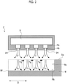
Fig. 2 is a cross-sectional view illustrating a configuration of a nozzle unit according to the first embodiment of the present disclosure. -
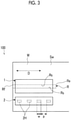
Fig. 3 is a top view illustrating a configuration of the laser processing device according to the first embodiment of the present disclosure. -
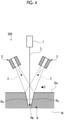
Fig. 4 is a cross-sectional view illustrating a configuration of a laser processing device according to a second embodiment of the present disclosure. -
Fig. 5 is a cross-sectional view illustrating a configuration of a laser processing device according to a third embodiment of the present disclosure. -
Fig. 6 is a cross-sectional view illustrating a configuration of a nozzle unit according to the third embodiment of the present disclosure. -
Fig. 7 is a cross-sectional view illustrating a modification example of the nozzle unit according to the third embodiment of the present disclosure. - Hereinafter, a
laser processing device 100 according to a first embodiment of the present disclosure will be described with reference toFigs. 1 to 3 . Thelaser processing device 100 is used for performing laser processing including machining or grooving on a workpiece W formed of a metal material or a carbon fiber reinforced resin (CFRP), for example. As illustrated inFig. 1 , thelaser processing device 100 includes alaser irradiation unit 1 and anozzle unit 2. - The
laser irradiation unit 1 irradiates a surface of the workpiece W (workpiece surface Sw) with laser light L to form a processing groove R on the workpiece surface Sw. Thelaser irradiation unit 1 is disposed at a position where the workpiece W can be irradiated with the laser light from vertically above. The term "vertically above" as used herein refers to a substantially vertical direction, and manufacturing errors and tolerances are allowed. Thelaser irradiation unit 1 causes the laser light L to reciprocate (perform scanning) on the workpiece surface Sw in a predetermined direction (hereinafter, referred to as a scanning direction D). In this manner, the processing groove R is formed by thermal energy of the laser light L. As the number of reciprocating times of the laser light L increases, a depth of the processing groove R gradually increases. Thelaser irradiation unit 1 can also be configured to linearly irradiate the workpiece surface Sw only once with the laser light L (that is, configured not to reciprocate). Furthermore, thelaser irradiation unit 1 can be configured to irradiate the workpiece surface Sw with the laser light L multiple times in only one direction. - In an example of
Fig. 1 or3 , the processing groove R has a linear shape extending in the scanning direction D on the workpiece surface Sw. Furthermore, as illustrated inFig. 1 , a bottom surface Rb of the processing groove R has a planar shape. A side surface Rs of the processing groove R spreads in a direction intersecting with the bottom surface Rb. That is, the processing groove R has a rectangular (more specifically, V-shaped or trapezoidal) cross section, when viewed in an extending direction of the processing groove R. The processing groove R may extend in a curved shape. - The
nozzle unit 2 is provided to supply a flow of gas (ejection flow F) to the processing groove R in a state of being irradiated with the laser light L. Thenozzle unit 2 is disposed at a position that does not interfere with the laser light L, when viewed in the scanning direction D. More specifically, thenozzle unit 2 ejects the gas (ejection flow F) to form an angle of 45° or more with respect to the workpiece W (workpiece surface Sw), when viewed in the scanning direction D. More preferably, the angle of the ejection flow F is 60° or larger. Most preferably, the angle of the ejection flow F is 85°. - Subsequently, a configuration of the
nozzle unit 2 will be described in detail with reference toFigs. 2 and3 . As illustrated in the drawings, a space V and a plurality ofejection holes 2H communicating with the space V are formed inside thenozzle unit 2. Compressed gas supplied from an external supply source (not illustrated) circulates in the space V. The plurality ofejection holes 2H are aligned at an interval in the scanning direction D, when viewed in a horizontal direction orthogonal to the scanning direction D. In an example inFig. 2 , an example having fourejection holes 2H is illustrated. However, the number of theejection holes 2H is not limited to four. - Each of the
ejection holes 2H has an enlarged portion Ha located on the space V side and a reduced portion Hb located on the workpiece W side from the enlarged portion Ha. A flow path cross-sectional area of the enlarged portion Ha is larger than a flow path cross-sectional area of the reduced portion Hb. An upper end portion of the enlarged portion Ha communicates with the space V. An upper end portion of the reduced portion Hb communicates with the enlarged portion Ha. A lower end portion of the reduced portion Hb is open downward toward the workpiece W. Theejection hole 2H does not necessarily have the enlarged portion Ha and the reduced portion Hb. For example, theejection hole 2H may be configured to have a trapezoidal cross section formed by continuously reducing an opening diameter from the space V toward the workpiece W. - As illustrated in
Fig. 3 , each of theejection holes 2H has a rectangular cross-sectional shape. Here, p>w is satisfied, when a dimension of theejection holes 2H in the longitudinal direction (that is, a dimension in the scanning direction D) is defined as w and an interval between a pair of theejection holes 2H adjacent to each other is defined as p. - Subsequently, an operation of the
laser processing device 100 according to the present embodiment will be described. In operating thelaser processing device 100, the workpiece surface Sw is first irradiated with the laser light L. The workpiece surface Sw is irradiated with the laser light L to form the above-described processing groove R on the workpiece surface Sw. Specifically, as illustrated inFig. 2 or3 , the processing groove R extending toward a tip portion Re is formed from a starting end portion Rf which is an end surface of the workpiece W toward one side in the scanning direction D of the laser light L. During this process, the bottom surface Rb and the side surface Rs (refer toFig. 3 ) are formed inside the processing groove R. - Incidentally, it is known that a plume is generated when laser processing is performed. When the plume is generated, a cutting surface (processing groove R) of the workpiece W may be degenerated due to an exposure to a high temperature of the plume, and a heat-affected layer may be formed on the cutting surface. In addition, in some cases, a carbon fiber reinforced resin (CFRP) may be processed by the above-described
laser processing device 100. When the laser processing is performed on the CFRP, a resin component is dropped out or carbonized, thereby forming the heat-affected layer. When the CFRP is applied to a product, the heat-affected layer is removed in general. In other words, in order to remove the heat-affected layer, there is a possibility that a manufacturing cost may increase or a work period may be prolonged. - Therefore, the present embodiment adopts a configuration as follows. The above-described
nozzle unit 2 supplies the ejection flow F into the processing groove R so that the laser processing is performed and the plume is removed at the same time. As illustrated inFig. 2 , the ejection flow F flows from the plurality ofejection holes 2H toward the processing groove R via the space V of thenozzle unit 2. A portion of the ejection flow F does not flow into the processing groove R, and flows outward away along the workpiece surface Sw. On the other hand, a residual component of the ejection flow F flows into the processing groove R, thereby forming an internal flow Fr. The internal flow Fr flows toward the bottom surface Rb from the workpiece surface Sw side. A pressure of the internal flow Fr increases when the internal flow Fr collides with the bottom surface Rb, and forms a collision jet flow flowing in the extending direction of the processing groove R. The collision jet flow and another collision jet flow formed by a jet flow from the adjacent ejection holes 2H collide with each other. In this manner, a flow direction is reversed to an upward direction. In this manner, a flow (scavenging flow Fg) flowing upward from the processing groove R is formed. Following the scavenging flow Fg, the plume staying inside the processing groove R is discharged outward of the processing groove R. - As described above, according to the above-described configuration, a high temperature plume generated inside the processing groove R can be blown outward by the gas ejected from the
nozzle unit 2. In particular, the plurality ofejection holes 2H of thenozzle unit 2 are aligned in the scanning direction D of thelaser irradiation unit 1. In this manner, the plume generated inside the processing groove R can be blown over an entire region in the extending direction of the processing groove. In this manner, it is possible to suppress thermal influence of the plume on an inner surface of the processing groove. - More specifically, according to the above-described configuration, the plume generated inside the processing groove R can be blown outward of the processing groove R by the scavenging flow Fg formed between the ejection flows F. In this manner, it is possible to suppress thermal influence of the plume on an inner surface of the processing groove. That is, it is not necessary to separately provide a dedicated device for forming the scavenging flow Fg. Therefore, a manufacturing cost and a maintenance cost of the
laser processing device 100 can be reduced. - Furthermore, in the above-described configuration, the scanning direction D of the ejection holes 2H is the longitudinal direction, and an interval between the ejection holes 2H adjacent to each other is larger than a dimension of the ejection holes 2H in the longitudinal direction. In this manner, the scavenging flow Fg directed outward of the processing groove R can be formed by reversing the ejection flows F on the bottom surface Rb of the processing groove R between the ejection flows F supplied from the ejection holes 2H. In this manner, the plume generated inside the processing groove R can be blown outward of the processing groove R. As a result, it is possible to suppress the thermal influence of the plume on the inner surface of the processing groove R.
- In addition, in the above-described configuration, the
laser irradiation unit 1 is configured to irradiate the workpiece W with the laser light L from vertically above. Thenozzle unit 2 is configured to eject the gas to form an angle of 45° or larger and 85° or smaller with respect to the workpiece W, when viewed in the scanning direction D. According to the above-described configuration, the ejection flow F can be stably supplied into the processing groove R while thelaser irradiation unit 1 and thenozzle unit 2 are prevented from interfering with each other. In this manner, the plume generated inside the processing groove R can be blown outward of the processing groove R. As a result, it is possible to suppress the thermal influence of the plume on the inner surface of the processing groove R. - Next, a second embodiment of the present disclosure will be described with reference to
Fig. 4 . The same reference numerals will be assigned to configurations the same as those in the first embodiment, and detailed description thereof will be omitted. As illustrated inFig. 4 , alaser processing device 200 according to the present embodiment is different from that according to the first embodiment in that a plurality of (two) thenozzle units 2 are provided. - The
laser irradiation unit 1 is configured to irradiate the workpiece W with the laser light L from vertically above. The twonozzle units 2 are provided on both sides in the horizontal direction (that is, the width direction of the processing groove R) orthogonal to the scanning direction D while thelaser irradiation unit 1 is interposed therebetween. Each of thenozzle units 2 supplies the ejection flow F toward the processing groove R. - According to the above-described configuration, the
nozzle units 2 are provided on both sides of the processing groove R in the width direction while thelaser irradiation unit 1 is interposed therebetween. In this manner, the gas can be stably supplied into the processing groove R from both sides in the width direction. Therefore, the plume generated inside the processing groove R can be more positively blown outward of the processing groove R. As a result, it is possible to further suppress the thermal influence of the plume on the inner surface of the processing groove R. Furthermore, according to the above-described configuration, the pressure of the jet flow (internal flow Fr) flowing into the processing groove R increases when the jet flow collides with the bottom surface Rb, thereby forming the collision jet flow flowing in the extending direction of the processing groove R. The collision jet flow and another collision jet flow formed by a jet flow from the adjacent ejection holes 2H collide with each other. In this manner, a flow direction is reversed to an upward direction. In this manner, a flow (scavenging flow Fg) flowing upward from the processing groove R is formed. Following the scavenging flow Fg, the plume staying inside the processing groove R can be positively discharged outward of the processing groove R. - Subsequently, a third embodiment of the present disclosure will be described with reference to
Figs. 5 and6 . The same reference numerals will be assigned to configurations the same as those in each of the above-described embodiments, and detailed description thereof will be omitted. In alaser processing device 300 according to the present embodiment, a configuration of thenozzle unit 2b is different from that of each of the above-described embodiments. As illustrated inFigs. 5 and6 , in addition to the space V and theejection hole 2H which are described above, a suction flow path Ps and a suction hole Hs are formed in thenozzle unit 2b. The suction flow path Ps is formed independently of the space V and theejection hole 2H. The suction flow path Ps is connected to a negative pressure pump (not illustrated) provided outside. A lower end portion of the suction holes Hs is open to a portion between the ejection holes 2H. An upper end portion of the suction hole Hs communicates with the suction flow path Ps. - According to the above-described configuration, the scavenging flow Fg including the plume transported from the inside of the processing groove R can be stably suctioned by the suction hole Hs formed in the
nozzle unit 2b. In this manner, it is possible to reduce a possibility that the scavenging flow Fg may stay inside the processing groove R. As a result, it is possible to further suppress the thermal influence of the plume on the inner surface of the processing groove R. - Hitherto, the embodiments of the present disclosure have been described in detail with reference to the drawings. However, specific configurations are not limited to the above-described embodiments, and design changes within the scope not departing from the concept of the present disclosure are also included.
- For example, in the above-described third embodiment, as illustrated in
Figs. 5 and6 , the configuration has been described in which theejection hole 2H and the suction hole Hs are formed in thenozzle unit 2b. However, as illustrated inFig. 6 , a configuration can be adopted in which asuction nozzle unit 2c having only a suction hole Hs' is provided separately from thenozzle unit 2 having only theejection hole 2H as described in the first embodiment. - The laser processing device described in each of the embodiments can be understood as follows, for example.
- (1) The
laser processing device 100 according to a first aspect includes thelaser irradiation unit 1 that forms the processing groove R extending in the scanning direction D on the workpiece W by performing the laser processing on the workpiece W while scanning the surface Sw of the workpiece W, and thenozzle unit 2 that has the plurality ofejection holes 2H aligned in the scanning direction D to eject the gas toward the processing groove R from each of the ejection holes 2H. - According to the above-described configuration, the high temperature plume generated inside the processing groove R can be blown by the gas ejected from the
nozzle unit 2. In particular, the plurality ofejection holes 2H of thenozzle unit 2 are aligned in the scanning direction D of thelaser irradiation unit 1. In this manner, the plume generated inside the processing groove R can be blown over the entire region in the extending direction of the processing groove R. In this manner, it is possible to suppress the thermal influence of the plume on the inner surface of the processing groove R. - (2) In the
laser processing device 100 according to a second aspect, between ejection flows F ejected from the ejection holes 2H inside the processing groove R, an interval between the ejection holes 2H is set so that the scavenging flow Fg formed by reversing the ejection flows F on the bottom surface Rb of the processing groove R is formed. - According to the above-described configuration, the plume generated inside the processing groove R can be blown outward of the processing groove R by the scavenging flow Fg formed between the ejection flows F. In this manner, it is possible to suppress the thermal influence of the plume on the inner surface of the processing groove R. That is, it is not necessary to separately provide a dedicated device for forming the scavenging flow Fg. Therefore, a manufacturing cost and a maintenance cost of the
laser processing device 100 can be reduced. - (3) In the
laser processing device 100 according to a third aspect, the scanning direction D of each of the ejection holes 2H is the longitudinal direction, and the interval between the ejection holes 2H adjacent to each other is larger than the dimension of theejection hole 2H in the longitudinal direction. - According to the above-described configuration, the scavenging flow Fg directed outward of the processing groove R can be formed between the ejection flows F supplied from the ejection holes 2H by reversing the ejection flows F on the bottom surface Rb of the processing groove R. In this manner, the plume generated inside the processing groove R can be blown outward of the processing groove R. As a result, it is possible to suppress the thermal influence of the plume on the inner surface of the processing groove R.
- (4) In the
laser processing device 100 according to a fourth aspect, thelaser irradiation unit 1 is configured to irradiate the workpiece W with the laser light L from vertically above, and thenozzle unit 2 is configured to eject the gas to form the angle of 45° or larger and 85° or smaller with respect to the workpiece W, when viewed in the scanning direction D. - According to the above-described configuration, the ejection flow F can be stably supplied into the processing groove R while the
laser irradiation unit 1 and thenozzle unit 2 are prevented from interfering with each other. In this manner, the plume generated inside the processing groove R can be blown outward of the processing groove R. As a result, it is possible to suppress the thermal influence of the plume on the inner surface of the processing groove R. - (5) In the
laser processing device 200 according to a fifth aspect, thelaser irradiation unit 1 is configured to irradiate the workpiece W with the laser light L from vertically above, and thenozzle units 2 are provided on both sides in the horizontal direction orthogonal to the scanning direction D while thelaser irradiation unit 1 is interposed therebetween. - According to the above-described configuration, the
nozzle units 2 are provided on both sides of the processing groove R in the width direction while thelaser irradiation unit 1 is interposed therebetween. In this manner, the gas can be stably supplied into the processing groove R from both sides in the width direction. Therefore, the plume generated inside the processing groove R can be more positively blown outward of the processing groove R. As a result, it is possible to further suppress the thermal influence of the plume on the inner surface of the processing groove R. - (6) In the
laser processing device 300 according to a sixth aspect, thenozzle unit 2b further has the suction hole Hs provided between the plurality ofejection holes 2H and suctioning the scavenging flow Fg. - According to the above-described configuration, the scavenging flow Fg including the plume transported from the inside of the processing groove R can be stably suctioned by the suction hole Hs formed in the
nozzle unit 2b. In this manner, it is possible to reduce a possibility that the scavenging flow Fg may stay inside the processing groove R. As a result, it is possible to further suppress the thermal influence of the plume on the inner surface of the processing groove R. - (7) The
laser processing device 400 according to a seventh aspect further includes thesuction nozzle unit 2c provided separately from thenozzle unit 2b and having the plurality of suction holes Hs' for suctioning the scavenging flow Fg. - According to the above-described configuration, the scavenging flow Fg including the plume transported from the inside of the processing groove R can be stably suctioned by the
suction nozzle unit 2c. In this manner, it is possible to reduce a possibility that the scavenging flow Fg may stay inside the processing groove R. As a result, it is possible to further suppress the thermal influence of the plume on the inner surface of the processing groove R. - In the above-described
laser processing device 100, the gas is ejected into the processing groove R by thenozzle unit 2 to remove the plume. Therefore, the formation of the heat-affected layer by the plume can be further suppressed. -
- 100, 200, 300, 400:
- Laser processing device
- 1:
- Laser irradiation unit
- 2, 2b:
- Nozzle unit
- 2c:
- Suction nozzle unit
- 2H:
- Ejection hole
- D:
- Scanning direction
- F:
- Ejection flow
- Fg:
- Scavenging flow
- Fr:
- Internal flow
- Ha:
- Enlarged portion
- Hb:
- Reduced portion
- Hs, Hs':
- Suction hole
- L:
- Laser light
- Ps:
- Suction flow path
- R:
- Processing groove
- Rb:
- Bottom surface
- Re:
- Tip portion
- Rf:
- Starting end portion
- Rs:
- Side surface
- Sw:
- Workpiece surface
- V:
- Space
- W:
- Workpiece
Claims (7)
- A laser processing device comprising:a laser irradiation unit that forms a processing groove extending in a scanning direction on a workpiece by performing laser processing on the workpiece while scanning a surface of the workpiece; anda nozzle unit that has a plurality of ejection holes aligned in the scanning direction to eject gas toward the processing groove from each of the ejection holes.
- The laser processing device according to claim 1, wherein between ejection flows ejected from the ejection holes inside the processing groove, an interval between the ejection holes is set so that a scavenging flow formed by reversing the ejection flows on a bottom surface of the processing groove is formed.
- The laser processing device according to claim 1 or 2,
wherein the scanning direction of each of the ejection holes is a longitudinal direction, and an interval between the ejection holes adjacent to each other is larger than a dimension of the ejection hole in the longitudinal direction. - The laser processing device according to any one of claims 1 to 3,wherein the laser irradiation unit is configured to irradiate the workpiece with laser light from vertically above, andthe nozzle unit is configured to eject the gas to form an angle of 45° or larger and 85° or smaller with respect to the workpiece, when viewed in the scanning direction.
- The laser processing device according to any one of claims 1 to 4,wherein the laser irradiation unit is configured to irradiate the workpiece with laser light from vertically above, andthe nozzle units are provided on both sides in a horizontal direction orthogonal to the scanning direction while the laser irradiation unit is interposed therebetween.
- The laser processing device according to any one of claims 2 to 5,
wherein the nozzle unit further has a suction hole provided between the plurality of ejection holes and suctioning the scavenging flow. - The laser processing device according to any one of claims 2 to 5, further comprising:
a suction nozzle unit provided separately from the nozzle unit and having a plurality of suction holes for suctioning the scavenging flow.
Applications Claiming Priority (1)
| Application Number | Priority Date | Filing Date | Title |
|---|---|---|---|
| PCT/JP2019/029934 WO2021019704A1 (en) | 2019-07-31 | 2019-07-31 | Laser processing device |
Publications (3)
| Publication Number | Publication Date |
|---|---|
| EP3943230A1 true EP3943230A1 (en) | 2022-01-26 |
| EP3943230A4 EP3943230A4 (en) | 2022-04-13 |
| EP3943230B1 EP3943230B1 (en) | 2025-06-25 |
Family
ID=74229405
Family Applications (1)
| Application Number | Title | Priority Date | Filing Date |
|---|---|---|---|
| EP19939724.1A Active EP3943230B1 (en) | 2019-07-31 | 2019-07-31 | Laser processing device |
Country Status (4)
| Country | Link |
|---|---|
| US (1) | US12257648B2 (en) |
| EP (1) | EP3943230B1 (en) |
| JP (1) | JPWO2021019704A1 (en) |
| WO (1) | WO2021019704A1 (en) |
Family Cites Families (16)
| Publication number | Priority date | Publication date | Assignee | Title |
|---|---|---|---|---|
| DE4120790A1 (en) * | 1991-06-24 | 1993-01-14 | Verkehrswesen Hochschule | NOZZLE FOR TREATMENT OF METAL WORKPIECES |
| GB9507719D0 (en) * | 1995-04-13 | 1995-05-31 | Boc Group Plc | Machining of materials |
| JPH1099978A (en) * | 1996-09-27 | 1998-04-21 | Hitachi Ltd | Laser processing equipment |
| DE19840926B4 (en) * | 1998-09-08 | 2013-07-11 | Hell Gravure Systems Gmbh & Co. Kg | Arrangement for material processing by means of laser beams and their use |
| JP3491550B2 (en) * | 1999-02-04 | 2004-01-26 | 株式会社デンソー | High-density energy beam processing method and apparatus |
| JP3864103B2 (en) * | 2002-03-05 | 2006-12-27 | 住友重機械工業株式会社 | Repetitive processing method and apparatus using pulse laser |
| JP2011036865A (en) | 2009-08-07 | 2011-02-24 | Hitachi Metals Ltd | Method of forming blind hole |
| GB2481190B (en) * | 2010-06-04 | 2015-01-14 | Plastic Logic Ltd | Laser ablation |
| JP5912264B2 (en) * | 2011-02-28 | 2016-04-27 | 日本発條株式会社 | Laser processing method and apparatus |
| JP6064228B2 (en) * | 2013-05-24 | 2017-01-25 | パナソニックIpマネジメント株式会社 | Laser cutting apparatus and laser cutting method |
| JP5663776B1 (en) * | 2014-03-27 | 2015-02-04 | 福井県 | Suction method, suction device, laser processing method, and laser processing device |
| JP6239481B2 (en) * | 2014-10-08 | 2017-11-29 | 株式会社東芝 | Welding device and nozzle device |
| JP6730032B2 (en) | 2016-01-15 | 2020-07-29 | 三菱重工業株式会社 | Gas nozzle and laser gouging device |
| JP6719231B2 (en) | 2016-02-29 | 2020-07-08 | 国立大学法人大阪大学 | Carbon fiber composite material processing method and processing apparatus |
| JP7105187B2 (en) * | 2016-10-20 | 2022-07-22 | Jswアクティナシステム株式会社 | LASER PROCESSING APPARATUS AND LASER PROCESSING METHOD |
| KR102376434B1 (en) * | 2018-01-17 | 2022-03-22 | 삼성디스플레이 주식회사 | Laser apparatus |
-
2019
- 2019-07-31 US US17/607,131 patent/US12257648B2/en active Active
- 2019-07-31 JP JP2021536530A patent/JPWO2021019704A1/ja not_active Ceased
- 2019-07-31 EP EP19939724.1A patent/EP3943230B1/en active Active
- 2019-07-31 WO PCT/JP2019/029934 patent/WO2021019704A1/en not_active Ceased
Also Published As
| Publication number | Publication date |
|---|---|
| EP3943230A4 (en) | 2022-04-13 |
| JPWO2021019704A1 (en) | 2021-02-04 |
| US20220203480A1 (en) | 2022-06-30 |
| EP3943230B1 (en) | 2025-06-25 |
| US12257648B2 (en) | 2025-03-25 |
| WO2021019704A1 (en) | 2021-02-04 |
Similar Documents
| Publication | Publication Date | Title |
|---|---|---|
| CN103906597B (en) | Laser cutting method and laser cutting device | |
| CN110202260B (en) | Method for laser cutting with optimized gas dynamic properties | |
| US11229980B2 (en) | Machines for the separative machining of plate-shaped workpieces | |
| US20230241721A1 (en) | Method and machine for cutting and removing workpiece parts from a plate-shaped material | |
| CN109862993B (en) | Method for cutting workpieces by means of a laser beam | |
| JP5172019B2 (en) | Wire electric discharge machining apparatus, wire electric discharge machining method, thin plate manufacturing method, and semiconductor wafer manufacturing method | |
| US10722978B2 (en) | Machine for separative machining of plate-shaped work pieces | |
| US9522442B2 (en) | Method for the cutting machining of workpieces using a laser beam | |
| KR20150043339A (en) | Cutting device | |
| US10265800B2 (en) | Welding apparatus and nozzle device | |
| KR102060673B1 (en) | Laser machining apparatus | |
| CN105377499A (en) | Method for removing, by means of a laser beam, a protrusion deposited on the surface of a workpiece when a through hole is formed | |
| JP2010120038A (en) | Laser beam machining apparatus and method | |
| CN118159384A (en) | Method for producing a workpiece part having a chamfered cutting edge | |
| US12257648B2 (en) | Laser processing device | |
| JP2017177155A (en) | Laser processing head | |
| US20200047297A1 (en) | Supporting a workpiece on support slats of a workpiece support | |
| US12122060B2 (en) | Method and machining tool for cutting workpieces and associated computer program product | |
| JP7081050B2 (en) | Laser processing equipment | |
| JP2005118849A (en) | Laser processing equipment | |
| CN113439005A (en) | Nozzle for laser processing and laser processing device | |
| JP2008194845A (en) | Manufacturing method of mold for forming honeycomb structure and grooving apparatus used therefor | |
| KR20180097373A (en) | Apparatus and method for processing metal material using nozzle | |
| JP2012035306A (en) | Laser beam machining method and apparatus therefor | |
| JP4123390B2 (en) | Hybrid machining apparatus and hybrid machining method |
Legal Events
| Date | Code | Title | Description |
|---|---|---|---|
| STAA | Information on the status of an ep patent application or granted ep patent |
Free format text: STATUS: THE INTERNATIONAL PUBLICATION HAS BEEN MADE |
|
| PUAI | Public reference made under article 153(3) epc to a published international application that has entered the european phase |
Free format text: ORIGINAL CODE: 0009012 |
|
| STAA | Information on the status of an ep patent application or granted ep patent |
Free format text: STATUS: REQUEST FOR EXAMINATION WAS MADE |
|
| 17P | Request for examination filed |
Effective date: 20211014 |
|
| AK | Designated contracting states |
Kind code of ref document: A1 Designated state(s): AL AT BE BG CH CY CZ DE DK EE ES FI FR GB GR HR HU IE IS IT LI LT LU LV MC MK MT NL NO PL PT RO RS SE SI SK SM TR |
|
| A4 | Supplementary search report drawn up and despatched |
Effective date: 20220316 |
|
| RIC1 | Information provided on ipc code assigned before grant |
Ipc: B23K 26/36 20140101ALI20220310BHEP Ipc: B23K 26/14 20140101ALI20220310BHEP Ipc: B23K 26/08 20140101ALI20220310BHEP Ipc: B23K 26/142 20140101AFI20220310BHEP |
|
| DAV | Request for validation of the european patent (deleted) | ||
| DAX | Request for extension of the european patent (deleted) | ||
| STAA | Information on the status of an ep patent application or granted ep patent |
Free format text: STATUS: EXAMINATION IS IN PROGRESS |
|
| 17Q | First examination report despatched |
Effective date: 20240216 |
|
| GRAP | Despatch of communication of intention to grant a patent |
Free format text: ORIGINAL CODE: EPIDOSNIGR1 |
|
| STAA | Information on the status of an ep patent application or granted ep patent |
Free format text: STATUS: GRANT OF PATENT IS INTENDED |
|
| INTG | Intention to grant announced |
Effective date: 20241025 |
|
| GRAJ | Information related to disapproval of communication of intention to grant by the applicant or resumption of examination proceedings by the epo deleted |
Free format text: ORIGINAL CODE: EPIDOSDIGR1 |
|
| STAA | Information on the status of an ep patent application or granted ep patent |
Free format text: STATUS: EXAMINATION IS IN PROGRESS |
|
| GRAP | Despatch of communication of intention to grant a patent |
Free format text: ORIGINAL CODE: EPIDOSNIGR1 |
|
| STAA | Information on the status of an ep patent application or granted ep patent |
Free format text: STATUS: GRANT OF PATENT IS INTENDED |
|
| INTC | Intention to grant announced (deleted) | ||
| INTG | Intention to grant announced |
Effective date: 20250317 |
|
| RIN1 | Information on inventor provided before grant (corrected) |
Inventor name: SHIMIZU, MASAHIKO Inventor name: NARITA, RYUICHI Inventor name: FUJIYA, YASUYUKI Inventor name: INOUE, AKIKO Inventor name: GOYA, SANEYUKI Inventor name: KOMATSU, YOSHINAO Inventor name: YOSHIDA, KAZUHIRO |
|
| GRAS | Grant fee paid |
Free format text: ORIGINAL CODE: EPIDOSNIGR3 |
|
| GRAA | (expected) grant |
Free format text: ORIGINAL CODE: 0009210 |
|
| STAA | Information on the status of an ep patent application or granted ep patent |
Free format text: STATUS: THE PATENT HAS BEEN GRANTED |
|
| AK | Designated contracting states |
Kind code of ref document: B1 Designated state(s): AL AT BE BG CH CY CZ DE DK EE ES FI FR GB GR HR HU IE IS IT LI LT LU LV MC MK MT NL NO PL PT RO RS SE SI SK SM TR |
|
| REG | Reference to a national code |
Ref country code: GB Ref legal event code: FG4D |
|
| REG | Reference to a national code |
Ref country code: CH Ref legal event code: EP |
|
| REG | Reference to a national code |
Ref country code: CH Ref legal event code: EP |
|
| REG | Reference to a national code |
Ref country code: IE Ref legal event code: FG4D |
|
| REG | Reference to a national code |
Ref country code: DE Ref legal event code: R096 Ref document number: 602019071793 Country of ref document: DE |
|
| PG25 | Lapsed in a contracting state [announced via postgrant information from national office to epo] |
Ref country code: FI Free format text: LAPSE BECAUSE OF FAILURE TO SUBMIT A TRANSLATION OF THE DESCRIPTION OR TO PAY THE FEE WITHIN THE PRESCRIBED TIME-LIMIT Effective date: 20250625 |
|
| PGFP | Annual fee paid to national office [announced via postgrant information from national office to epo] |
Ref country code: DE Payment date: 20250728 Year of fee payment: 7 |
|
| REG | Reference to a national code |
Ref country code: LT Ref legal event code: MG9D |
|
| PG25 | Lapsed in a contracting state [announced via postgrant information from national office to epo] |
Ref country code: NO Free format text: LAPSE BECAUSE OF FAILURE TO SUBMIT A TRANSLATION OF THE DESCRIPTION OR TO PAY THE FEE WITHIN THE PRESCRIBED TIME-LIMIT Effective date: 20250925 Ref country code: GR Free format text: LAPSE BECAUSE OF FAILURE TO SUBMIT A TRANSLATION OF THE DESCRIPTION OR TO PAY THE FEE WITHIN THE PRESCRIBED TIME-LIMIT Effective date: 20250926 |
|
| PG25 | Lapsed in a contracting state [announced via postgrant information from national office to epo] |
Ref country code: BG Free format text: LAPSE BECAUSE OF FAILURE TO SUBMIT A TRANSLATION OF THE DESCRIPTION OR TO PAY THE FEE WITHIN THE PRESCRIBED TIME-LIMIT Effective date: 20250625 |
|
| PG25 | Lapsed in a contracting state [announced via postgrant information from national office to epo] |
Ref country code: HR Free format text: LAPSE BECAUSE OF FAILURE TO SUBMIT A TRANSLATION OF THE DESCRIPTION OR TO PAY THE FEE WITHIN THE PRESCRIBED TIME-LIMIT Effective date: 20250625 |
|
| PGFP | Annual fee paid to national office [announced via postgrant information from national office to epo] |
Ref country code: FR Payment date: 20250707 Year of fee payment: 7 |
|
| PG25 | Lapsed in a contracting state [announced via postgrant information from national office to epo] |
Ref country code: RS Free format text: LAPSE BECAUSE OF FAILURE TO SUBMIT A TRANSLATION OF THE DESCRIPTION OR TO PAY THE FEE WITHIN THE PRESCRIBED TIME-LIMIT Effective date: 20250925 |
|
| PG25 | Lapsed in a contracting state [announced via postgrant information from national office to epo] |
Ref country code: LV Free format text: LAPSE BECAUSE OF FAILURE TO SUBMIT A TRANSLATION OF THE DESCRIPTION OR TO PAY THE FEE WITHIN THE PRESCRIBED TIME-LIMIT Effective date: 20250625 |
|
| REG | Reference to a national code |
Ref country code: NL Ref legal event code: MP Effective date: 20250625 |
|
| PG25 | Lapsed in a contracting state [announced via postgrant information from national office to epo] |
Ref country code: NL Free format text: LAPSE BECAUSE OF FAILURE TO SUBMIT A TRANSLATION OF THE DESCRIPTION OR TO PAY THE FEE WITHIN THE PRESCRIBED TIME-LIMIT Effective date: 20250625 |
|
| PG25 | Lapsed in a contracting state [announced via postgrant information from national office to epo] |
Ref country code: PT Free format text: LAPSE BECAUSE OF FAILURE TO SUBMIT A TRANSLATION OF THE DESCRIPTION OR TO PAY THE FEE WITHIN THE PRESCRIBED TIME-LIMIT Effective date: 20251027 |
|
| REG | Reference to a national code |
Ref country code: AT Ref legal event code: MK05 Ref document number: 1805980 Country of ref document: AT Kind code of ref document: T Effective date: 20250625 |
|
| PG25 | Lapsed in a contracting state [announced via postgrant information from national office to epo] |
Ref country code: IS Free format text: LAPSE BECAUSE OF FAILURE TO SUBMIT A TRANSLATION OF THE DESCRIPTION OR TO PAY THE FEE WITHIN THE PRESCRIBED TIME-LIMIT Effective date: 20251025 |
|
| PG25 | Lapsed in a contracting state [announced via postgrant information from national office to epo] |
Ref country code: AT Free format text: LAPSE BECAUSE OF FAILURE TO SUBMIT A TRANSLATION OF THE DESCRIPTION OR TO PAY THE FEE WITHIN THE PRESCRIBED TIME-LIMIT Effective date: 20250625 Ref country code: SM Free format text: LAPSE BECAUSE OF FAILURE TO SUBMIT A TRANSLATION OF THE DESCRIPTION OR TO PAY THE FEE WITHIN THE PRESCRIBED TIME-LIMIT Effective date: 20250625 |
|
| PG25 | Lapsed in a contracting state [announced via postgrant information from national office to epo] |
Ref country code: CZ Free format text: LAPSE BECAUSE OF FAILURE TO SUBMIT A TRANSLATION OF THE DESCRIPTION OR TO PAY THE FEE WITHIN THE PRESCRIBED TIME-LIMIT Effective date: 20250625 |
|
| PG25 | Lapsed in a contracting state [announced via postgrant information from national office to epo] |
Ref country code: PL Free format text: LAPSE BECAUSE OF FAILURE TO SUBMIT A TRANSLATION OF THE DESCRIPTION OR TO PAY THE FEE WITHIN THE PRESCRIBED TIME-LIMIT Effective date: 20250625 |
|
| PG25 | Lapsed in a contracting state [announced via postgrant information from national office to epo] |
Ref country code: EE Free format text: LAPSE BECAUSE OF FAILURE TO SUBMIT A TRANSLATION OF THE DESCRIPTION OR TO PAY THE FEE WITHIN THE PRESCRIBED TIME-LIMIT Effective date: 20250625 |
|
| PG25 | Lapsed in a contracting state [announced via postgrant information from national office to epo] |
Ref country code: SK Free format text: LAPSE BECAUSE OF FAILURE TO SUBMIT A TRANSLATION OF THE DESCRIPTION OR TO PAY THE FEE WITHIN THE PRESCRIBED TIME-LIMIT Effective date: 20250625 |
|
| PG25 | Lapsed in a contracting state [announced via postgrant information from national office to epo] |
Ref country code: ES Free format text: LAPSE BECAUSE OF FAILURE TO SUBMIT A TRANSLATION OF THE DESCRIPTION OR TO PAY THE FEE WITHIN THE PRESCRIBED TIME-LIMIT Effective date: 20250625 |
|
| REG | Reference to a national code |
Ref country code: CH Ref legal event code: H13 Free format text: ST27 STATUS EVENT CODE: U-0-0-H10-H13 (AS PROVIDED BY THE NATIONAL OFFICE) Effective date: 20260224 |
|
| PG25 | Lapsed in a contracting state [announced via postgrant information from national office to epo] |
Ref country code: RO Free format text: LAPSE BECAUSE OF FAILURE TO SUBMIT A TRANSLATION OF THE DESCRIPTION OR TO PAY THE FEE WITHIN THE PRESCRIBED TIME-LIMIT Effective date: 20250625 Ref country code: LU Free format text: LAPSE BECAUSE OF NON-PAYMENT OF DUE FEES Effective date: 20250731 |
|
| REG | Reference to a national code |
Ref country code: BE Ref legal event code: MM Effective date: 20250731 |
|
| PG25 | Lapsed in a contracting state [announced via postgrant information from national office to epo] |
Ref country code: MC Free format text: LAPSE BECAUSE OF FAILURE TO SUBMIT A TRANSLATION OF THE DESCRIPTION OR TO PAY THE FEE WITHIN THE PRESCRIBED TIME-LIMIT Effective date: 20250625 |
|
| PG25 | Lapsed in a contracting state [announced via postgrant information from national office to epo] |
Ref country code: DK Free format text: LAPSE BECAUSE OF FAILURE TO SUBMIT A TRANSLATION OF THE DESCRIPTION OR TO PAY THE FEE WITHIN THE PRESCRIBED TIME-LIMIT Effective date: 20250625 |
|
| PG25 | Lapsed in a contracting state [announced via postgrant information from national office to epo] |
Ref country code: IT Free format text: LAPSE BECAUSE OF FAILURE TO SUBMIT A TRANSLATION OF THE DESCRIPTION OR TO PAY THE FEE WITHIN THE PRESCRIBED TIME-LIMIT Effective date: 20250625 Ref country code: BE Free format text: LAPSE BECAUSE OF NON-PAYMENT OF DUE FEES Effective date: 20250731 |
|
| PG25 | Lapsed in a contracting state [announced via postgrant information from national office to epo] |
Ref country code: CH Free format text: LAPSE BECAUSE OF NON-PAYMENT OF DUE FEES Effective date: 20250731 |
|
| PLBE | No opposition filed within time limit |
Free format text: ORIGINAL CODE: 0009261 |
|
| STAA | Information on the status of an ep patent application or granted ep patent |
Free format text: STATUS: NO OPPOSITION FILED WITHIN TIME LIMIT |
|
| REG | Reference to a national code |
Ref country code: CH Ref legal event code: L10 Free format text: ST27 STATUS EVENT CODE: U-0-0-L10-L00 (AS PROVIDED BY THE NATIONAL OFFICE) Effective date: 20260507 |