EP3943041B1 - Dental prosthesis coloring device, coloring method and associated devices - Google Patents
Dental prosthesis coloring device, coloring method and associated devices Download PDFInfo
- Publication number
- EP3943041B1 EP3943041B1 EP20772863.5A EP20772863A EP3943041B1 EP 3943041 B1 EP3943041 B1 EP 3943041B1 EP 20772863 A EP20772863 A EP 20772863A EP 3943041 B1 EP3943041 B1 EP 3943041B1
- Authority
- EP
- European Patent Office
- Prior art keywords
- coloring
- prosthesis
- axis
- unit
- dental prosthesis
- Prior art date
- Legal status (The legal status is an assumption and is not a legal conclusion. Google has not performed a legal analysis and makes no representation as to the accuracy of the status listed.)
- Active
Links
- 238000004040 coloring Methods 0.000 title claims description 167
- 238000000034 method Methods 0.000 title claims description 27
- 238000003754 machining Methods 0.000 claims description 101
- 238000010304 firing Methods 0.000 claims description 28
- 238000003860 storage Methods 0.000 claims description 21
- 238000001035 drying Methods 0.000 claims description 18
- 239000000919 ceramic Substances 0.000 claims description 7
- 229910052691 Erbium Inorganic materials 0.000 claims description 3
- 229910052693 Europium Inorganic materials 0.000 claims description 3
- 229910052771 Terbium Inorganic materials 0.000 claims description 3
- 229910052775 Thulium Inorganic materials 0.000 claims description 3
- 229910052804 chromium Inorganic materials 0.000 claims description 3
- 229910052802 copper Inorganic materials 0.000 claims description 3
- 229910052742 iron Inorganic materials 0.000 claims description 3
- 229910052748 manganese Inorganic materials 0.000 claims description 3
- 229910052759 nickel Inorganic materials 0.000 claims description 3
- 229910052719 titanium Inorganic materials 0.000 claims description 3
- 229910052720 vanadium Inorganic materials 0.000 claims description 3
- 229910052710 silicon Inorganic materials 0.000 claims description 2
- 239000000976 ink Substances 0.000 description 45
- 210000003128 head Anatomy 0.000 description 36
- 238000005520 cutting process Methods 0.000 description 32
- 230000007246 mechanism Effects 0.000 description 13
- 239000000463 material Substances 0.000 description 12
- 238000013461 design Methods 0.000 description 10
- 238000010586 diagram Methods 0.000 description 10
- 230000008569 process Effects 0.000 description 9
- NJPPVKZQTLUDBO-UHFFFAOYSA-N novaluron Chemical compound C1=C(Cl)C(OC(F)(F)C(OC(F)(F)F)F)=CC=C1NC(=O)NC(=O)C1=C(F)C=CC=C1F NJPPVKZQTLUDBO-UHFFFAOYSA-N 0.000 description 8
- 238000009500 colour coating Methods 0.000 description 6
- XEEYBQQBJWHFJM-UHFFFAOYSA-N iron Substances [Fe] XEEYBQQBJWHFJM-UHFFFAOYSA-N 0.000 description 6
- PXHVJJICTQNCMI-UHFFFAOYSA-N nickel Substances [Ni] PXHVJJICTQNCMI-UHFFFAOYSA-N 0.000 description 6
- 239000003086 colorant Substances 0.000 description 5
- MCMNRKCIXSYSNV-UHFFFAOYSA-N Zirconium dioxide Chemical compound O=[Zr]=O MCMNRKCIXSYSNV-UHFFFAOYSA-N 0.000 description 4
- 239000011651 chromium Substances 0.000 description 4
- 239000010949 copper Substances 0.000 description 4
- 239000000428 dust Substances 0.000 description 4
- 230000006870 function Effects 0.000 description 4
- 239000011572 manganese Substances 0.000 description 4
- 238000012986 modification Methods 0.000 description 4
- 230000004048 modification Effects 0.000 description 4
- 239000010936 titanium Substances 0.000 description 4
- 238000004891 communication Methods 0.000 description 3
- 239000007943 implant Substances 0.000 description 3
- 238000003780 insertion Methods 0.000 description 3
- 230000037431 insertion Effects 0.000 description 3
- 239000002904 solvent Substances 0.000 description 3
- VYZAMTAEIAYCRO-UHFFFAOYSA-N Chromium Chemical compound [Cr] VYZAMTAEIAYCRO-UHFFFAOYSA-N 0.000 description 2
- RYGMFSIKBFXOCR-UHFFFAOYSA-N Copper Chemical compound [Cu] RYGMFSIKBFXOCR-UHFFFAOYSA-N 0.000 description 2
- PWHULOQIROXLJO-UHFFFAOYSA-N Manganese Chemical compound [Mn] PWHULOQIROXLJO-UHFFFAOYSA-N 0.000 description 2
- 229910052777 Praseodymium Inorganic materials 0.000 description 2
- RTAQQCXQSZGOHL-UHFFFAOYSA-N Titanium Chemical compound [Ti] RTAQQCXQSZGOHL-UHFFFAOYSA-N 0.000 description 2
- 238000013473 artificial intelligence Methods 0.000 description 2
- 229910052797 bismuth Inorganic materials 0.000 description 2
- JCXGWMGPZLAOME-UHFFFAOYSA-N bismuth atom Chemical compound [Bi] JCXGWMGPZLAOME-UHFFFAOYSA-N 0.000 description 2
- 229910010293 ceramic material Inorganic materials 0.000 description 2
- 239000010941 cobalt Substances 0.000 description 2
- 229910017052 cobalt Inorganic materials 0.000 description 2
- GUTLYIVDDKVIGB-UHFFFAOYSA-N cobalt atom Chemical compound [Co] GUTLYIVDDKVIGB-UHFFFAOYSA-N 0.000 description 2
- 238000010981 drying operation Methods 0.000 description 2
- UYAHIZSMUZPPFV-UHFFFAOYSA-N erbium Chemical compound [Er] UYAHIZSMUZPPFV-UHFFFAOYSA-N 0.000 description 2
- OGPBJKLSAFTDLK-UHFFFAOYSA-N europium atom Chemical compound [Eu] OGPBJKLSAFTDLK-UHFFFAOYSA-N 0.000 description 2
- 210000004283 incisor Anatomy 0.000 description 2
- 239000004973 liquid crystal related substance Substances 0.000 description 2
- 238000004519 manufacturing process Methods 0.000 description 2
- PUDIUYLPXJFUGB-UHFFFAOYSA-N praseodymium atom Chemical compound [Pr] PUDIUYLPXJFUGB-UHFFFAOYSA-N 0.000 description 2
- 238000012545 processing Methods 0.000 description 2
- 239000002994 raw material Substances 0.000 description 2
- GZCRRIHWUXGPOV-UHFFFAOYSA-N terbium atom Chemical compound [Tb] GZCRRIHWUXGPOV-UHFFFAOYSA-N 0.000 description 2
- LEONUFNNVUYDNQ-UHFFFAOYSA-N vanadium atom Chemical compound [V] LEONUFNNVUYDNQ-UHFFFAOYSA-N 0.000 description 2
- 241000282465 Canis Species 0.000 description 1
- 239000000654 additive Substances 0.000 description 1
- 230000000996 additive effect Effects 0.000 description 1
- 238000013019 agitation Methods 0.000 description 1
- 239000012237 artificial material Substances 0.000 description 1
- 210000004763 bicuspid Anatomy 0.000 description 1
- 239000011248 coating agent Substances 0.000 description 1
- 238000000576 coating method Methods 0.000 description 1
- 230000007547 defect Effects 0.000 description 1
- 239000005548 dental material Substances 0.000 description 1
- 230000000694 effects Effects 0.000 description 1
- 239000012530 fluid Substances 0.000 description 1
- 239000010720 hydraulic oil Substances 0.000 description 1
- 239000011256 inorganic filler Substances 0.000 description 1
- 229910003475 inorganic filler Inorganic materials 0.000 description 1
- 238000009434 installation Methods 0.000 description 1
- 238000005259 measurement Methods 0.000 description 1
- 229910052751 metal Inorganic materials 0.000 description 1
- 239000002184 metal Substances 0.000 description 1
- 210000000214 mouth Anatomy 0.000 description 1
- 230000035699 permeability Effects 0.000 description 1
- 239000000049 pigment Substances 0.000 description 1
- 229920000642 polymer Polymers 0.000 description 1
- 239000011148 porous material Substances 0.000 description 1
- 238000007639 printing Methods 0.000 description 1
- 230000009467 reduction Effects 0.000 description 1
- 239000011347 resin Substances 0.000 description 1
- 229920005989 resin Polymers 0.000 description 1
- 239000010703 silicon Substances 0.000 description 1
- 238000005245 sintering Methods 0.000 description 1
- 230000000007 visual effect Effects 0.000 description 1
- XLYOFNOQVPJJNP-UHFFFAOYSA-N water Substances O XLYOFNOQVPJJNP-UHFFFAOYSA-N 0.000 description 1
Images


Classifications
-
- A—HUMAN NECESSITIES
- A61—MEDICAL OR VETERINARY SCIENCE; HYGIENE
- A61C—DENTISTRY; APPARATUS OR METHODS FOR ORAL OR DENTAL HYGIENE
- A61C13/00—Dental prostheses; Making same
- A61C13/08—Artificial teeth; Making same
- A61C13/082—Cosmetic aspects, e.g. inlays; Determination of the colour
-
- A—HUMAN NECESSITIES
- A61—MEDICAL OR VETERINARY SCIENCE; HYGIENE
- A61C—DENTISTRY; APPARATUS OR METHODS FOR ORAL OR DENTAL HYGIENE
- A61C13/00—Dental prostheses; Making same
- A61C13/08—Artificial teeth; Making same
- A61C13/083—Porcelain or ceramic teeth
-
- A—HUMAN NECESSITIES
- A61—MEDICAL OR VETERINARY SCIENCE; HYGIENE
- A61C—DENTISTRY; APPARATUS OR METHODS FOR ORAL OR DENTAL HYGIENE
- A61C5/00—Filling or capping teeth
- A61C5/70—Tooth crowns; Making thereof
- A61C5/77—Methods or devices for making crowns
-
- B—PERFORMING OPERATIONS; TRANSPORTING
- B41—PRINTING; LINING MACHINES; TYPEWRITERS; STAMPS
- B41J—TYPEWRITERS; SELECTIVE PRINTING MECHANISMS, i.e. MECHANISMS PRINTING OTHERWISE THAN FROM A FORME; CORRECTION OF TYPOGRAPHICAL ERRORS
- B41J3/00—Typewriters or selective printing or marking mechanisms characterised by the purpose for which they are constructed
- B41J3/407—Typewriters or selective printing or marking mechanisms characterised by the purpose for which they are constructed for marking on special material
- B41J3/4073—Printing on three-dimensional objects not being in sheet or web form, e.g. spherical or cubic objects
-
- B—PERFORMING OPERATIONS; TRANSPORTING
- B41—PRINTING; LINING MACHINES; TYPEWRITERS; STAMPS
- B41M—PRINTING, DUPLICATING, MARKING, OR COPYING PROCESSES; COLOUR PRINTING
- B41M5/00—Duplicating or marking methods; Sheet materials for use therein
- B41M5/0041—Digital printing on surfaces other than ordinary paper
- B41M5/0047—Digital printing on surfaces other than ordinary paper by ink-jet printing
-
- B—PERFORMING OPERATIONS; TRANSPORTING
- B41—PRINTING; LINING MACHINES; TYPEWRITERS; STAMPS
- B41M—PRINTING, DUPLICATING, MARKING, OR COPYING PROCESSES; COLOUR PRINTING
- B41M5/00—Duplicating or marking methods; Sheet materials for use therein
- B41M5/0041—Digital printing on surfaces other than ordinary paper
- B41M5/007—Digital printing on surfaces other than ordinary paper on glass, ceramic, tiles, concrete, stones, etc.
-
- B—PERFORMING OPERATIONS; TRANSPORTING
- B41—PRINTING; LINING MACHINES; TYPEWRITERS; STAMPS
- B41M—PRINTING, DUPLICATING, MARKING, OR COPYING PROCESSES; COLOUR PRINTING
- B41M5/00—Duplicating or marking methods; Sheet materials for use therein
- B41M5/0082—Digital printing on bodies of particular shapes
- B41M5/0088—Digital printing on bodies of particular shapes by ink-jet printing
-
- A—HUMAN NECESSITIES
- A61—MEDICAL OR VETERINARY SCIENCE; HYGIENE
- A61C—DENTISTRY; APPARATUS OR METHODS FOR ORAL OR DENTAL HYGIENE
- A61C2201/00—Material properties
- A61C2201/002—Material properties using colour effect, e.g. for identification purposes
-
- F—MECHANICAL ENGINEERING; LIGHTING; HEATING; WEAPONS; BLASTING
- F27—FURNACES; KILNS; OVENS; RETORTS
- F27B—FURNACES, KILNS, OVENS, OR RETORTS IN GENERAL; OPEN SINTERING OR LIKE APPARATUS
- F27B17/00—Furnaces of a kind not covered by any preceding group
- F27B17/02—Furnaces of a kind not covered by any preceding group specially designed for laboratory use
- F27B17/025—Furnaces of a kind not covered by any preceding group specially designed for laboratory use for dental workpieces
Definitions
- the present disclosure relates to a dental prosthesis coloring device, a machining apparatus including the coloring device, and a coloring method.
- the color of the prosthesis after machining is different from the hue of the patient's natural teeth because the color of the prosthesis is the color of the ceramic material itself. Therefore, a coloring agent which develops color by firing is applied to the surface of the prosthesis, and then the prosthesis is fired to form a sintered body, thereby adjusting the hue of the prosthesis closer to the patient's natural teeth and to a more natural hue to enhance aesthetics.
- the coloring operation of the prosthesis is carried out by, for example, a dental technician using an applicator such as a brush, by adding different colors for different parts, and therefore a skilled technique is required, which requires labor and time. Variations in color tone may also occur depending on the skill of, for example, a dental technician, and stable color tone may not be obtained.
- Patent Literature 2 discloses a method of manufacturing a prosthesis in which the surface of the prosthesis is automatically colored by printing a colored ink by an inkjet method.
- Patent literature 3 discloses a method for manufacturing dental prostheses processing blocks in which a mold, the inner surface of which has the shape of the outer shape of a block, is partially filled with a resin material which contains an inorganic filler and then rotational agitation is performed, followed by polymer curing.
- Patent Literature 2 an oily ink containing a pigment as a main component is used, so that a prosthesis made of a porous material such as ceramics is difficult to penetrate the ink and difficult to produce a good finish.
- the present disclosure has been made in view of the above circumstances, and enables to color a dental prosthesis more easily, more quickly, efficiently and with a good finish.
- a dental prosthesis coloring device is a coloring device for coloring a dental prosthesis by an inkjet method, the device including an inkjet head having a nozzle that ejects ink droplets, a holding unit that holds the prosthesis, a drive unit that moves the inkjet head or the holding unit in a predetermined direction in an XYZ orthogonal coordinate system, and a control unit that controls the inkjet head and the drive unit, in which the control unit is configured to control the inkjet head and the drive unit based on predetermined coloring data and three-dimensional data of the prosthesis and.
- the present disclosure enables to color a dental prosthesis more easily, more quickly, efficiently and with a good finish.
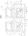
- FIG. 1 is a diagram illustrating a schematic configuration of a machining apparatus 100 including a coloring device 20 according to the first embodiment
- FIG. 2 is a block diagram illustrating a schematic configuration of the machining apparatus 100.
- the machining apparatus 100 includes a machining apparatus main body 10, a coloring device 20, and a control device 30.
- the machining apparatus 100 may include, for example, a measuring device such as a digital camera, a digital video camera and a 3D scanner for acquiring an image of, for example, a tooth, a negative or a positive, and a firing device for firing a prosthesis P.
- the control device 30 controls the entire operation of the machining apparatus 100, but also functions as a controller for each of the machining apparatus main body 10 and the coloring device 20.
- the control device 30 may also function as a design device for designing three-dimensional data and coloring data used for machining and coloring a workpiece B.
- the control device 30 will be described in detail below.
- an X-axis, a Y-axis and a Z-axis of XYZ orthogonal coordinates are set herein.
- the present description will be described in which in FIG. 1 , the horizontal direction is the X-axis direction, the front-rear direction is the Y-axis direction, and the vertical direction is the Z-axis direction.
- the X-axis direction corresponds to the main scanning direction of the coloring device 20, and the Y-axis direction corresponds to the sub-scanning direction of the coloring device 20.
- the machining apparatus main body 10 and the coloring device 20 are provided in parallel in a housing 1 covered by a cover member 1a.
- the housing 1 is provided inside with a machining chamber 2 for cutting the workpiece B by the machining apparatus main body 10 and a coloring chamber 3 for coloring the prosthesis P obtained by the machining by the coloring device 20.
- the machining apparatus main body 10 and the coloring device 20 are provided with door bodies 4, 5, respectively, for taking in and out the workpiece B and the prosthesis P so as to be freely opened and closed.
- the machining apparatus main body 10 is a device for cutting the workpiece B to produce the dental prosthesis P such as a crown, bridge or implant (see FIG. 3A ).
- the machining apparatus main body 10 includes a cutting unit 11, a workpiece holding unit 12, a drive unit 15 having a cutting unit drive unit 13 and a holding unit drive unit 14, and a control device 30.
- the machining apparatus main body 10 includes, for example, a dust collecting pipe and a dust collecting device for collecting and removing dust in the machining space 2a.
- a known and suitable CAD/CAM machining apparatus having these configurations can be applied as the machining apparatus main body 10.
- the cutting unit 11 is provided in the machining space 2a of the machining chamber 2, and cuts the workpiece B which is a raw material of the dental prosthesis P to produce the prosthesis P.
- the cutting unit 11 is movable in the X-axis direction and the Z-axis direction by the cutting unit drive unit 13.
- the cutting unit 11 is constituted of a spindle 11a and a tool 11b which is detachably provided on the spindle 11a and composed of, for example, a ball end mill.
- the spindle 11a is rotated with the Z-axis as the rotation axis by the cutting unit drive unit 13.
- the rotation with, for example, the Z-axis as the axis of rotation is hereinafter referred to as a "rotation about the Z-axis", for example.
- the workpiece holding unit 12 is provided in the machining space 2a of the machining chamber 2 to detachably hold the workpiece B.
- the workpiece holding unit 12 is movable in the Y-axis direction by the holding unit drive unit 14 and is rotatable about the X-axis.
- the components of the cutting unit 11, and the workpiece holding unit 12 can be moved in the above-mentioned direction.
- the relative positional relationship between the tool 11b of the cutting unit 11 and the workpiece B held by the workpiece holding unit 12 can be changed in any direction of the X-axis direction, the Y-axis direction, and the Z-axis direction. Therefore, the machining apparatus main body 10 can perform three-dimensional machining of the workpiece B.
- the cutting unit drive unit 13 moves the cutting unit 11 in the X-axis direction and the Z-axis direction and rotates about the Z-axis under the control of the control unit 31 of the control device 30. Therefore, the cutting unit drive unit 13 more specifically includes an X-axis direction drive mechanism, a Z-axis direction drive mechanism, and a Z-axis rotary drive mechanism, for example.
- the holding unit drive unit 14 moves the workpiece holding unit 12 in the Y-axis direction and rotates about the X-axis under the control of the control unit 31 of the control device 30. Therefore, the holding unit drive unit 14 more specifically includes a Y-axis direction drive mechanism and an X-axis rotary drive mechanism, for example.
- the cutting unit drive unit 13 and the holding unit drive unit 14 can be constituted of a ball screw mechanism, a rack and pinion mechanism, a crank slider mechanism, a fluid cylinder which moves linearly by pneumatic pressure, hydraulic water pressure or hydraulic oil pressure, a spindle motor, or an electric motor, for example.
- FIG. 3A illustrates an example of the workpiece B and the prosthesis P obtained by machining the workpiece B.
- the workpiece B for example, a block body having a substantially cubic shape is used, but the workpiece is not limited thereto, and may be any known body.
- a metal mounting member 6 for mounting the workpiece B to the workpiece holding unit 12 is adhesively fixed.
- the mounting member 6 is provided with a pedestal 6a and a pin 6b projecting from the pedestal 6a.
- the material (raw material) of the workpiece B and the prosthesis P may be any material used as a dental material, such as a crown, a bridge or an implant, for example, and is not limited to any particular type.
- a ceramic-based porous body having excellent biocompatibility and strength when completed as a prosthesis after sintering is suitably used, and among these materials, a zirconia porous body is most suitably used because of having higher biocompatibility and strength and also being excellent in aesthetics.
- the coloring device 20 is a device for coloring the prosthesis P machined by a machining apparatus main body 10 by an inkjet method.
- the coloring device 20 mainly includes an inkjet head 22 having a nozzle 21, a prosthesis holding unit 23, a drive unit 26 having a head drive unit 24 and a holding unit drive unit 25, and a control device 30.
- the inkjet head (hereinafter referred to simply as a "head") 22 is provided in the coloring space 3a of the coloring chamber 3 and has at least one nozzle 21 for ejecting ink droplets of colored ink.
- the colored ink is supplied to the head 22 from an ink supply source such as an ink tank.
- an ink supply source such as an ink tank.
- the head 22 is provided with an ejection mechanism for ejecting ink droplets from the nozzle 21.
- the ejection type of the ejection mechanism is not limited to any particular type, and a type generally used for inkjet printers such as a piezo type or a thermal type can be applied.
- the head 22 is mounted to a guide rail 16 arranged along the main scanning direction (X-axis direction in the present description), and is movable at least in the main scanning direction (X-axis direction) by the head drive unit 24.
- the head 22 may be movable in the sub-scanning direction (Y-axis direction in the present description) intersecting the main scanning direction, or may also be movable in a direction (Z-axis direction in the present description) intersecting these directions.
- the head 22 is movable in the X-axis direction and the Y-axis direction by the head drive unit 24, and is also movable in the Y-axis direction while reciprocating in the X-axis direction, but may be movable in the X-axis direction while reciprocating in the Y-axis direction.
- the moving member is not limited to the head 22, and the prosthesis holding unit 23 may be movable in these directions.
- the head 22 and the prosthesis holding unit 23 may be relatively movable in at least any directions of the X-axis, Y-axis, and Z-axis directions, more preferably in two directions of the X-axis and Y-axis directions, and still more preferably in three directions of the X-axis, Y-axis, and Z-axis directions.
- the colored ink is a colored ink used for coloring the dental prosthesis P.
- the colored ink may be used in an inkjet printer, and is not limited to any particular type.
- a ceramic-based porous body such as zirconia
- the colored ink an appropriate one can be used depending on the material and properties of the prosthesis P.
- the colored ink desirably contains at least any of Ti (titanium), V (vanadium), Cr (chromium), Mn (manganese), Fe (iron), Co (cobalt), Ni (nickel), Cu (copper), Bi (bismuth), Pr (praseodymium), Eu (europium), Tb (terbium), Er (erbium), Tm (thulium), or oxides thereof.
- the colored ink desirably contains at least any of Ti (titanium), V (vanadium), Cr (chromium), Mn (manganese), Fe (iron), Co (cobalt), Ni (nickel), Cu (copper), Bi (bismuth), Pr (praseodymium), Eu (europium), Tb (terbium), Er (erbium), Tm (thulium), Si (silicon), or oxides thereof. Containing these components allows the prostheses P after firing to be developed in a hue closer to that of natural teeth.
- the colored ink may contain one component or two or more components selected from these components, depending on the color of the colored ink, the material of the prosthesis P to be applied, the properties, or the color developing method, for example.
- the colored ink is not limited to one containing these components, but may contain other components.
- the colored ink also contains a solvent, an additive and other component necessary as the colored ink of the inkjet type coloring device 20.
- the colored ink contains a coloring material which disappears by firing so that the operator can grasp the application state by visual observation.
- the prosthesis P is automatically colored by the coloring device 20, so that containing such a coloring material is not required.
- a coloring material may be contained, and for example, the operator can easily confirm whether the prosthesis P is before coloring or after coloring.
- FIG. 3B illustrates an example of a color coating pattern according to the type and shape of the prosthesis P.
- the type of the colored ink is not limited to any particular type as long as the ink contains the above-mentioned components, and may be an aqueous ink, an oily ink, or a solvent-based ink.
- the aqueous ink is most suitable from the viewpoint of permeability to the ceramic-based porous body and burden on the firing furnace.
- the prosthesis holding unit 23 is provided in the coloring space 3a of the coloring chamber 3 to detachably hold the prosthesis P. Since the mounting member 6 to the workpiece holding unit 12 of the machining apparatus main body 10 is connected to the prosthesis P, the prosthesis holding unit 23 is provided with a hole portion 23a for inserting and fixing the pedestal 6a and the pin 6b so as to utilize the mounting member 6. The insertion of the pedestal 6a and the pin 6b into the hole portion 23a allows the prosthesis P to be fixed by the prosthesis holding unit 23, and unexpected falling and looseness to be suppressed.
- the surface of the prosthesis P which is visible from the outside when worn in the oral cavity may be colored to ensure aesthetics. More preferably, if coloring can be applied to a wider range such as the outer edge and the back surface of the prosthesis P, the aesthetics can be further improved. Therefore, in the present embodiment, in order to apply coloring to a wider range of the prosthesis P, the holding unit drive unit 25 is configured to be able to rotate the prosthesis holding unit 23 about the X-axis.
- the head drive unit 24 includes an X-axis direction drive unit 24a for moving the head 22 in the X-axis direction, and a Y-axis direction drive unit 24b for moving the head 22 in the Y-axis direction.
- the holding unit drive unit 25 includes an X-axis rotary drive unit 25a for rotating the prosthesis holding unit 23 about the X-axis.
- the head drive unit 24 may further include, for example, a Z-axis direction drive unit or the like for moving the head 22 or the prosthesis holding unit 23 in the Z-axis direction, so that coloring of the three-dimensional prosthesis P can be performed more elaborately.
- the control device 30 controls the operation of the entire machining apparatus 100 including the control of the machining apparatus main body 10 and the coloring device 20.
- the control device 30 is mainly constituted of, for example, a personal computer (PC) or a microcomputer provided with a Central Processing Unit (CPU), a Read Only Memory (ROM), a Random Access Memory (RAM), a non-volatile storage such as a hard disk drive and a flash memory, a communication interface, and an external recording medium interface, for example.
- PC personal computer
- CPU Central Processing Unit
- ROM Read Only Memory
- RAM Random Access Memory
- non-volatile storage such as a hard disk drive and a flash memory
- communication interface such as a hard disk drive and a flash memory
- an external recording medium interface for example.
- the control device 30 includes a display unit 33 and an input unit 34, for example.
- the display unit 33 includes, for example, a liquid crystal display, and displays, for example, an operation screen of the machining apparatus main body 10 and the coloring device 20.
- the input unit 34 includes, for example, a touch panel, a keyboard, a mouse, an operation button which are mounted on the liquid crystal display, and can input, for example, various operation instructions to the control device 30.
- the control device 30 functionally includes a control unit 31 and a storage unit 32.
- the control unit 31 is constituted of, for example, a CPU
- the storage unit 32 is constituted of a RAM, a ROM, and a nonvolatile storage.
- the storage unit 32 also includes an external recording medium accessible via an external recording medium interface. Examples of the external recording medium include an SD card, a USB memory, a CD, and a DVD.
- the CPU uses the RAM as a work area to read out and execute an operating system or other programs stored in the storage unit 32 such as a ROM, thereby controlling the operation of the entire machining apparatus 100.
- the storage unit 32 stores, for example, the various programs and parameters used by the programs. Further, the storage unit 32 stores, for example, three-dimensional data or coloring data for machining the workpiece B in the machining apparatus main body 10 and coloring the prosthesis P in the coloring device 20.
- the control unit 31 controls the machining apparatus main body 10, drives the drive unit 15 to move or rotate a cutting unit 11 and the workpiece holding unit 12, and drives the cutting unit 11 to cut the workpiece B. Further, on the basis of the three-dimensional data and the coloring data, the control unit 31 controls the coloring device 20, drives the drive unit 26 to move or rotate the head 22 and the prosthesis holding unit 23, and ejects ink droplets from the nozzle 21 to color the prosthesis P.
- the three-dimensional data is a three-dimensional coordinate address representing the three-dimensional shape of the prosthesis P to be machined or colored.
- the three-dimensional data is generated by, for example, an external design device, and stored in the storage unit 32 by using an external recording medium such as an SD card.
- the machining apparatus 100 may acquire three-dimensional data from a design device connected via a wired or a wireless communication device and store the data in the storage unit 32.
- three-dimensional data of the existing machining apparatus can also be used.
- three-dimensional data can be acquired from an existing machining apparatus using an external recording medium or a communication device and stored in the storage unit 32.
- the control device 30 may have a function as a design device, and the control device 30 may generate three-dimensional data.
- a measurement device such as a 3D scanner scans a patient's tooth, a negative or a positive, and the operator designs the three-dimensional shape of the prosthesis P based on the scan data.
- the control unit 31 generates three-dimensional data based on the design and stores the generated data in the storage unit 32.
- the generation of the three-dimensional data can be performed using a known method using general-purpose software, for example.
- the coloring data is stored in such a manner that color information is associated with a color coating pattern (gradation pattern) for each tooth shape or portion (e.g., upper and lower central incisors, lateral incisors, canines, premolars, or molars).
- the color information may be primary color values represented by RGB and CMYK values and color data corresponding to these values, or may be shade numbers and the color data corresponding to the shade numbers.
- the color information may be a combination of symbols given to each color data.
- the three-dimensional reference data of a plurality of prostheses having different shapes and the coloring patterns associated with the respective reference data may be stored in the storage unit 32, and the control unit 31 may compare the three-dimensional data of the prostheses P with the reference data to automatically select the corresponding coloring data.
- the operator may input a color number from the input unit 34, and the control unit 31 may select the coloring data from the storage unit 32 based on the color number.
- the control unit 31 may generate the coloring data based on the design.
- the control unit 31 may analyze an image of a patient's tooth taken by, for example, a camera to select coloring data.
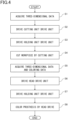
- the machining process includes a cutting process (cutting method) performed by the machining apparatus main body 10 and a coloring process (coloring method) performed by the coloring device 20.
- the cutting process and the coloring process may be carried out continuously or only one of the processes may be carried out independently. A case where the machining apparatus 100 continuously performs the cutting process and the coloring process will be described below.
- the operator turns on the power of the machining apparatus 100, mounts the workpiece B to the workpiece holding unit 12 of the machining apparatus main body 10, closes the door body 4, and gives the instruction to start cutting from the input unit 34.
- the machining apparatus main body 10 acquires the instruction to start cutting, the cutting process is started.
- step S1 the control unit 31 first acquires three-dimensional data for machining from the storage unit 32.
- step S2 the control unit 31 then drives the cutting unit drive unit 13 based on the three-dimensional data, and rotates the spindle 11a while moving the cutting unit 11.
- step S3 the control unit 31 drives the holding unit drive unit 14 as necessary to move and rotate the workpiece holding unit 12.
- the workpiece B is then cut while the cutting unit 11 moves according to the three-dimensional data (step S4).
- the prosthesis P having a desired shape is produced.
- the operator then takes out the prosthesis P obtained in step S4 from the machining apparatus main body 10, mounts the prosthesis to the prosthesis holding unit 23 of the coloring device 20, and inputs a coloring start instruction from the input unit 34.
- the coloring device 20 receives the coloring start instruction and starts the coloring process.
- the control unit 31 first acquires the three-dimensional data and the coloring data from, for example, the storage unit 32.
- the coloring data may be predetermined or may be selected and acquired from the storage unit 32 based on, for example, the color number inputted from the input unit 34 by the operator.
- step S6 the control unit 31 then drives the head drive unit 24 based on the three-dimensional data to move the head 22 in the X-axis direction and the Y-axis direction.
- step S7 the control unit 31 drives the holding unit drive unit 25 as necessary to move and rotate the prosthesis holding unit 23.
- step S8 the control unit 31 then controls the head 22 based on the coloring data while adjusting the position of the head 22 by the head drive unit 24 (and further rotating the prosthesis holding unit 23 by the holding unit drive unit 25 as necessary), and ejects ink droplets from the nozzle 21 to color the prosthesis P.
- the above operation allows the prosthesis P to be colored with a desired color and color coating pattern.
- the prosthesis P is then fired by the firing device to form a sintered body, so that the prosthesis P having a hue closer to the natural color can be obtained.
- the coloring device 20 and the machining apparatus 100 including the coloring device 20 drive the drive unit 26 under the control of the control unit 31, and control the inkjet head 22 to eject ink droplets from the nozzle 21 while moving the inkjet head 22 or the prosthesis holding unit 23 in a predetermined direction (e.g., in at least any of the X-axis, Y-axis, and Z-axis directions) in the XYZ orthogonal coordinate system.
- the machining apparatus 100 colors the three-dimensional prosthesis P in a desired color and a color coating pattern. In comparison with manual coloring, coating unevenness and variation in color tone are suppressed to enable coloring in a more uniform and stable color tone. Accordingly, it is possible to provide the coloring device 20, the machining apparatus 100, and the coloring method that can color the dental prosthesis P more easily, more quickly, efficiently and with a good finish.
- the machining apparatus main body 10 and other existing machining apparatuses incorporate three-dimensional data used for machining as three-dimensional data for coloring in the coloring device 20.
- coloring can be performed by the same coordinate system as in the machining of the prosthesis P, appropriate and more accurate coloring can be performed according to the machining shape, and the coloring operation can be performed more efficiently.
- the first embodiment is such that the machining apparatus main body 10 and the coloring device 20 are provided in parallel and the machining space 2a and the coloring space 3a are separate spaces, but is not limited to this configuration.
- the machining of the workpiece B and the coloring of the prosthesis P may be performed in one space.
- the cutting unit 11 and the head 22 are arranged in the space, respectively, or arranged in the space replaceably, and the workpiece holding unit 12 is also used as the prosthesis holding unit 23.
- the holding unit and the holding unit drive unit can be integrated into one.
- the workpiece B held by the holding unit is cut by the cutting unit 11 to produce the prosthesis P, and after a process such as dust treatment is performed, coloring can be continuously performed by using the head 22 while the prosthesis P is held by the holding unit, and labor for attachment and detachment can be eliminated.
- a part or whole of the drive units of the cutting unit 11 and the head 22 can be concurrently used.
- the holding unit may be configured to freely move in and out of the machining chamber 2 and the coloring chamber 3.
- This configuration allows the workpiece B to be cut in the machining space 2a of the machining chamber 2, and then the prosthesis P obtained to be moved from the machining chamber 2 to the coloring chamber 3 by the holding unit, and the prosthesis P to be colored in the coloring space 3a.
- the labor for taking in and out the prosthesis P by the operator is eliminated, and the operating time is shortened and the operation is simplified.
- the first embodiment is such that the coloring device 20 is incorporated into the machining apparatus 100, but is not limited to this configuration.
- the coloring device 20 having the configuration such as the first embodiment may be manufactured and provided as a single unit.
- the coloring device 20 can color the prosthesis P machined by the existing machining apparatus. Therefore, the user can continue to use the already installed machining apparatus and only need to install a new coloring device 20, thus reducing the installation cost.
- FIG. 5 is a diagram illustrating a schematic configuration of a main portion of the coloring device 20A according to the second embodiment
- FIG. 6 is a block diagram illustrating a schematic configuration of the coloring device 20A.
- the coloring device 20A according to the second embodiment is a device for coloring a prosthesis P machined by a predetermined machining apparatus 10' by an inkjet method. As illustrated in FIGS. 5 , 6 , the coloring device 20A according to the second embodiment mainly includes an inkjet head (head) 22 having a nozzle 21, a prosthesis holding unit 23, a drive unit 26 having a head drive unit 24 and a holding unit drive unit 25, and a control device 30.
- the control device 30 includes a control unit 31 and a storage unit 32, and is further provided with a display unit 33 and an input unit 34.
- the head 22 having the nozzle 21 is provided in the coloring space 3a of the coloring device 20A.
- the mechanism for ejecting the colored ink and the ink droplets from the nozzle 21 can be the same as that in the first embodiment.
- the head drive unit 24 includes a Z-axis direction drive unit 24c for moving the head 22 in the Z-axis direction.
- the Z-axis direction drive unit 24c includes a guide rail 40, a slider 41 movably provided on the guide rail 40, and a drive motor for moving the slider 41, for example.
- the head 22 is fixed to the slider 41.
- the Z-axis direction drive unit 24c can freely adjust the height of the head 22 by moving the head 22 in the Z-axis direction.
- the holding unit drive unit 25 includes an XY-axis direction drive unit 25b for moving the prosthesis holding unit 23 in the X-axis direction and the Y-axis direction, and an XYZ-axis rotary drive unit 25c for rotating the prosthesis holding unit 23 about the X-axis, Y-axis, and Z-axis.
- the XY-axis direction drive unit 25b includes a first guide rail 50 extending in the X-axis direction, a second guide rail 51 extending in the Y-axis direction, a slider 52 provided movably on the first and second guide rails 50, 51, and a drive motor for moving the slider 52, for example. Since the XY-axis direction drive unit 25b has the first and second guide rails 50, 51 extending in the X-axis direction and the Y-axis direction, respectively, the prosthesis holding unit 23 can be moved in the two-dimensional direction of XY.
- the XYZ-axis rotary drive unit 25c is fixed on the slider 52.
- the XYZ-axis rotary drive unit 25c includes: a fixed portion 60 fixed to the slider 52; a first arm unit 61 rotatably provided on the fixed portion 60 about the Z-axis (a third axis A3); a second arm unit 62 rotatably provided on the first arm unit 61 about a first axis A1 intersecting the Z-axis; a third arm unit 63 rotatably provided on the second arm unit 62 about the first axis A1; and a fourth arm unit 64 rotatably provided on the third arm unit 63 about a second axis A2 intersecting the first axis A1.
- the prosthesis holding unit 23 is fixed to the distal end of the fourth arm unit 64, and is rotatable about the second axis A2 together with the fourth arm unit 64.
- the first axis A1 is substantially matched with the X-axis
- the second axis A2 is substantially matched with the Y-axis.
- the rotation of the first arm unit 61 about the Z-axis or the rotation of the third arm unit 63 about the first axis A1 causes the first axis A1 and the second axis A2 to be mismatched with the X-axis or the Y-axis.
- the first axis A1 may be substantially matched with the Y-axis and the second axis A2 may be substantially matched with the X-axis, depending on the rotational position about the Z-axis.
- first axis A1 and the second axis A2 may intersect the X-axis, the Y-axis, and the Z-axis.
- the XYZ-axis rotary drive unit 25c can rotate the prosthesis holding unit 23 about three axes: the Z-axis, and the first axis A1 and the second axis A2 different from the Z-axis. Therefore, the XYZ-axis rotary drive unit 25c can arrange the prosthesis P held by the prosthesis holding unit 23 at a desired position and posture with respect to the nozzle 21.
- the coloring device 20A of the second embodiment having the above-described configuration basically performs the processes of steps S5 to S8 illustrated in FIG. 4 to color the prosthesis P.
- the operator first mounts the prosthesis P to be colored to the prosthesis holding unit 23 and inputs a coloring start instruction from the input unit 34.
- the coloring device 20A starts a coloring process, and in step S5, the control unit 31 acquires three-dimensional data and coloring data from the storage unit 32 and the external recording medium, the external PC (design device), or the existing machining apparatus 10'.
- the control unit 31 drives the Z-axis direction drive unit 24c of the head drive unit 24 as necessary to adjust the height of the head 22, based on the three-dimensional data.
- the control unit 31 drives the XY-axis direction drive unit 25b of the holding unit drive unit 25 to move the slider 52 on the first and second guide rails 50, 51, and to position the XYZ-axis rotary drive unit 25c and the prosthesis holding unit 23 on the slider 52 in the X-axis direction and the Y-axis direction.
- the control unit 31 drives the XYZ-axis rotary drive unit 25c to appropriately perform rotation of the first arm unit 61 about the Z-axis, rotation of the second and third arm units 62, 63 about the first axis A1, and rotation of the fourth arm unit 64 about the second axis A2.
- the prosthesis P held by the prosthesis holding unit 23 facing the nozzle 21 is arranged at a desired position and a desired posture (angle) in the XYZ space.
- step S8 the control unit 31 then controls the head 22 based on the coloring data while appropriately changing the position and posture of the prosthesis P with respect to the nozzle 21 by the XYZ-axis rotary drive unit 25c to eject ink droplets from the nozzle 21 to color the prosthesis P.
- the coloring device 20A of the second embodiment can color the prosthesis P in a desired color and a color coating pattern in a more uniform and stable color tone by the inkjet head 22 based on the three-dimensional data and the coloring data, as in the first embodiment. Therefore, the coloring device 20A can color the prosthesis P more easily, more quickly, efficiently and with a good finish.
- the XYZ-axis rotary drive unit 25c is rotatable about the Z-axis (third axis A3), about the first axis A1, and about the second axis A2, so that the prosthesis P can be arranged at a desired position in the XYZ space in a desired posture. Therefore, not only the occlusal face and the buccal face of the prosthesis P but also a wider range can be three-dimensionally colored, and the coloring accuracy and finish can be further improved to obtain the prosthesis P having higher aesthetics.
- the coloring device 20A of the second embodiment is provided as a single device separate from the machining apparatus, the coloring device 20A may be incorporated into the machining apparatus.
- the machining apparatus 100 of the first embodiment may incorporate the coloring device 20A according to the second embodiment instead of the coloring device 20.
- Such a machining apparatus also allows machining and coloring to be efficiently performed to obtain a prosthesis P having a good finish.
- the coloring devices 20, 20A may include a colorimetric device such as a digital camera, a digital video camera, and a colorimeter.
- the color of the patient's natural teeth is acquired by the colorimetric device, the color of the colored ink and the coloring pattern are determined by a control unit 31 based on the acquired color, and the color of the prosthesis P is colored.
- a coloring enables to eliminate the labor of designing and to color the prosthesis P in a hue close to that of natural teeth, thereby improving aesthetics.
- the control device 30 may also be mounted with artificial intelligence (AI).
- AI artificial intelligence
- three-dimensional data and coloring data are designed by AI, more rapid and more precise data can be obtained, and a prosthesis P closer to the shape and hue of the natural tooth and having higher aesthetics can be obtained.
- the coloring devices 20, 20A may be provided in a device having another function.
- the present disclosure includes a drying device including the dental prosthesis coloring device described above.
- the drying device may be provided as a single device separate from the coloring device or may be incorporated with the coloring device.
- the combination of the coloring device and the drying device may be incorporated into another device (e.g., a machining apparatus).
- the solvent amount of the ink is calculated with respect to the use amount of the ink used by the operator, and then the drying device is used, thereby enabling efficient drying operation with an optimum drying time.
- the control unit automatically calculates an optimum drying time in accordance with the amount of ink used and the operation time required for coloring, thereby enabling efficient drying operation with the optimum drying time.
- the mechanism of the drying device is not limited to any particular type, and may be an electric heater type, a warm air type, an IH type, or a microwave type.
- FIG. 7 An example of an embodiment of a machining apparatus provided with the drying device is illustrated in FIG. 7 .
- a machining apparatus 100A illustrated in FIG. 7 is a modification of the first embodiment, in which the machining apparatus 100 including the coloring device 20 of the first embodiment further includes a drying device 70. Therefore, the same configuration as in the first embodiment will not be described.
- the drying device 70 includes a prosthesis holding unit 71 for detachably holding the prosthesis P in a drying space 7a of a drying chamber 7 having a door body 7b, and a heat source 72 for drying the prosthesis P.
- the prosthesis holding unit 71 is provided with a hole portion 71a for inserting and fixing the pedestal 6a and the pin 6b so as to utilize the mounting member 6.
- the insertion of the pedestal 6a and the pin 6b into the hole portion 71a allows the prosthesis P to be fixed by the prosthesis holding unit 71, and unexpected falling during drying to be suppressed.
- the machining apparatus 100A may include the coloring device 20A of the second embodiment instead of the coloring device 20.
- the present disclosure includes a firing device including the dental prosthesis coloring device described above.
- the firing device may be provided as a single device separate from the coloring device or may be incorporated with the coloring device.
- the combination of the coloring device and the firing device may be incorporated into another apparatus (e.g., a machining apparatus).
- the operator calculates an optimum firing schedule with respect to the size of the prosthesis and the amount of ink used, and then uses the firing device, thereby enabling efficient firing operation.
- the firing device further includes a control unit, the control unit automatically calculates an optimum firing schedule in accordance with the amount of ink used and the operation time required for coloring, thereby enabling efficient firing operation with the optimum firing schedule.
- the mechanism of the firing device is not limited to any particular type, and may be an electric heater type, an IH type, or a microwave type.
- FIG. 8 An example of an embodiment of a machining apparatus provided with the firing device is illustrated in FIG. 8 .
- a machining apparatus 100B illustrated in FIG. 8 is another modification of the first embodiment, in which the machining apparatus 100 including the coloring device 20 of the first embodiment further includes a firing device 80.
- the firing device 80 includes a prosthesis holding unit 81 for detachably holding the prosthesis P in a firing space 8a of a firing chamber 8 having a door body 8b, and a heat source 82 for firing the prosthesis P.
- the prosthesis holding unit 81 is provided with a hole portion 81a for inserting and fixing the pedestal 6a and the pin 6b so as to utilize the mounting member 6.
- the machining apparatus 100B may include the coloring device 20A of the second embodiment instead of the coloring device 20.
Description
- The present disclosure relates to a dental prosthesis coloring device, a machining apparatus including the coloring device, and a coloring method.
- In recent years, ceramic materials with high biocompatibility and strength have been widely used in prosthodontic treatment such as crown treatment and implant treatment in which tooth defects are repaired with artificial materials (prostheses). As a technique for producing a prosthesis using such a material, a machining apparatus has been developed which acquires three-dimensional data of a patient's tooth form and machines a ceramic-based block material into a prosthesis of a desired shape by, for example, laser machining based on the three-dimensional data (e.g., refer to Patent Literature 1).
- The color of the prosthesis after machining is different from the hue of the patient's natural teeth because the color of the prosthesis is the color of the ceramic material itself. Therefore, a coloring agent which develops color by firing is applied to the surface of the prosthesis, and then the prosthesis is fired to form a sintered body, thereby adjusting the hue of the prosthesis closer to the patient's natural teeth and to a more natural hue to enhance aesthetics.
- However, the coloring operation of the prosthesis is carried out by, for example, a dental technician using an applicator such as a brush, by adding different colors for different parts, and therefore a skilled technique is required, which requires labor and time. Variations in color tone may also occur depending on the skill of, for example, a dental technician, and stable color tone may not be obtained.
- On the other hand,
Patent Literature 2 discloses a method of manufacturing a prosthesis in which the surface of the prosthesis is automatically colored by printing a colored ink by an inkjet method. -
Patent literature 3 discloses a method for manufacturing dental prostheses processing blocks in which a mold, the inner surface of which has the shape of the outer shape of a block, is partially filled with a resin material which contains an inorganic filler and then rotational agitation is performed, followed by polymer curing. -
- Patent Literature 1:
JP 2017-6445 A - Patent Literature 2:
JP 2010-220882 A - Patent Literature 3:
WO2009154301 A - However, in the invention described in
Patent Literature 2, an oily ink containing a pigment as a main component is used, so that a prosthesis made of a porous material such as ceramics is difficult to penetrate the ink and difficult to produce a good finish. - The present disclosure has been made in view of the above circumstances, and enables to color a dental prosthesis more easily, more quickly, efficiently and with a good finish.
- In order to achieve the above object, a dental prosthesis coloring device according to the present disclosure is a coloring device for coloring a dental prosthesis by an inkjet method, the device including an inkjet head having a nozzle that ejects ink droplets, a holding unit that holds the prosthesis, a drive unit that moves the inkjet head or the holding unit in a predetermined direction in an XYZ orthogonal coordinate system, and a control unit that controls the inkjet head and the drive unit, in which the control unit is configured to control the inkjet head and the drive unit based on predetermined coloring data and three-dimensional data of the prosthesis and.
- The present disclosure enables to color a dental prosthesis more easily, more quickly, efficiently and with a good finish.
-
-
FIG. 1 is a diagram illustrating a schematic configuration of a dental prosthesis machining apparatus including a dental prosthesis coloring device according to a first embodiment. -
FIG. 2 is a block diagram illustrating a schematic configuration of the machining apparatus illustrated inFIG. 1 . -
FIG. 3A is an illustration for explaining a workpiece and a prosthesis, and illustrates an example of a workpiece and a prosthesis obtained by cutting the workpiece. -
FIG. 3B is an illustration for explaining a workpiece and a prosthesis, and illustrates a colored image of the prosthesis. -
FIG. 4 is a flowchart illustrating an example of a flow of operations of a machining process (cutting process and coloring process) performed by the machining apparatus illustrated inFIG. 1 . -
FIG. 5 is a diagram illustrating a schematic configuration of a main portion of a dental prosthesis coloring device according to a second embodiment. -
FIG. 6 is a block diagram illustrating a schematic configuration of the coloring device illustrated inFIG. 5 . -
FIG. 7 is a diagram illustrating a schematic configuration of a modification of the dental prosthesis machining apparatus including the dental prosthesis coloring device according to the first embodiment, in which the machining apparatus further includes a drying device. -
FIG. 8 is a diagram illustrating a schematic configuration of another modification of the dental prosthesis machining apparatus including the dental prosthesis coloring device according to the first embodiment, in which the machining apparatus further includes a firing device. - A dental prosthesis coloring device (hereinafter referred to simply as a "coloring device") and a dental prosthesis machining apparatus including the coloring device according to a first embodiment will be described below with reference to the drawings.
FIG. 1 is a diagram illustrating a schematic configuration of amachining apparatus 100 including acoloring device 20 according to the first embodiment, andFIG. 2 is a block diagram illustrating a schematic configuration of themachining apparatus 100. - As illustrated in
FIG. 1 , themachining apparatus 100 according to the first embodiment includes a machining apparatusmain body 10, acoloring device 20, and acontrol device 30. Alternatively, themachining apparatus 100 may include, for example, a measuring device such as a digital camera, a digital video camera and a 3D scanner for acquiring an image of, for example, a tooth, a negative or a positive, and a firing device for firing a prosthesis P. - The
control device 30 controls the entire operation of themachining apparatus 100, but also functions as a controller for each of the machining apparatusmain body 10 and thecoloring device 20. Thecontrol device 30 may also function as a design device for designing three-dimensional data and coloring data used for machining and coloring a workpiece B. Thecontrol device 30 will be described in detail below. - In the present description, as illustrated in
FIG. 1 , an X-axis, a Y-axis and a Z-axis of XYZ orthogonal coordinates are set herein. The present description will be described in which inFIG. 1 , the horizontal direction is the X-axis direction, the front-rear direction is the Y-axis direction, and the vertical direction is the Z-axis direction. The X-axis direction corresponds to the main scanning direction of thecoloring device 20, and the Y-axis direction corresponds to the sub-scanning direction of thecoloring device 20. - The machining apparatus
main body 10 and thecoloring device 20 are provided in parallel in ahousing 1 covered by a cover member 1a. Thehousing 1 is provided inside with amachining chamber 2 for cutting the workpiece B by the machining apparatusmain body 10 and acoloring chamber 3 for coloring the prosthesis P obtained by the machining by thecoloring device 20. The machining apparatusmain body 10 and thecoloring device 20 are provided withdoor bodies - The machining apparatus
main body 10 is a device for cutting the workpiece B to produce the dental prosthesis P such as a crown, bridge or implant (seeFIG. 3A ). The machining apparatusmain body 10 includes acutting unit 11, aworkpiece holding unit 12, adrive unit 15 having a cuttingunit drive unit 13 and a holdingunit drive unit 14, and acontrol device 30. The machining apparatusmain body 10 includes, for example, a dust collecting pipe and a dust collecting device for collecting and removing dust in themachining space 2a. In the present embodiment, a known and suitable CAD/CAM machining apparatus having these configurations can be applied as the machining apparatusmain body 10. - The
cutting unit 11 is provided in themachining space 2a of themachining chamber 2, and cuts the workpiece B which is a raw material of the dental prosthesis P to produce the prosthesis P. Thecutting unit 11 is movable in the X-axis direction and the Z-axis direction by the cuttingunit drive unit 13. Thecutting unit 11 is constituted of aspindle 11a and atool 11b which is detachably provided on thespindle 11a and composed of, for example, a ball end mill. Thespindle 11a is rotated with the Z-axis as the rotation axis by the cuttingunit drive unit 13. The rotation with, for example, the Z-axis as the axis of rotation is hereinafter referred to as a "rotation about the Z-axis", for example. - The
workpiece holding unit 12 is provided in themachining space 2a of themachining chamber 2 to detachably hold the workpiece B. In order to enable three-dimensional machining of the workpiece B, theworkpiece holding unit 12 is movable in the Y-axis direction by the holdingunit drive unit 14 and is rotatable about the X-axis. - The components of the
cutting unit 11, and theworkpiece holding unit 12 can be moved in the above-mentioned direction. Thus, the relative positional relationship between thetool 11b of thecutting unit 11 and the workpiece B held by theworkpiece holding unit 12 can be changed in any direction of the X-axis direction, the Y-axis direction, and the Z-axis direction. Therefore, the machining apparatusmain body 10 can perform three-dimensional machining of the workpiece B. - The cutting
unit drive unit 13 moves thecutting unit 11 in the X-axis direction and the Z-axis direction and rotates about the Z-axis under the control of thecontrol unit 31 of thecontrol device 30. Therefore, the cuttingunit drive unit 13 more specifically includes an X-axis direction drive mechanism, a Z-axis direction drive mechanism, and a Z-axis rotary drive mechanism, for example. - The holding
unit drive unit 14 moves theworkpiece holding unit 12 in the Y-axis direction and rotates about the X-axis under the control of thecontrol unit 31 of thecontrol device 30. Therefore, the holdingunit drive unit 14 more specifically includes a Y-axis direction drive mechanism and an X-axis rotary drive mechanism, for example. - The cutting
unit drive unit 13 and the holdingunit drive unit 14 can be constituted of a ball screw mechanism, a rack and pinion mechanism, a crank slider mechanism, a fluid cylinder which moves linearly by pneumatic pressure, hydraulic water pressure or hydraulic oil pressure, a spindle motor, or an electric motor, for example. -
FIG. 3A illustrates an example of the workpiece B and the prosthesis P obtained by machining the workpiece B. As the workpiece B, for example, a block body having a substantially cubic shape is used, but the workpiece is not limited thereto, and may be any known body. On one surface of the workpiece B, ametal mounting member 6 for mounting the workpiece B to theworkpiece holding unit 12 is adhesively fixed. The mountingmember 6 is provided with apedestal 6a and apin 6b projecting from thepedestal 6a. - The material (raw material) of the workpiece B and the prosthesis P may be any material used as a dental material, such as a crown, a bridge or an implant, for example, and is not limited to any particular type. For example, a ceramic-based porous body having excellent biocompatibility and strength when completed as a prosthesis after sintering is suitably used, and among these materials, a zirconia porous body is most suitably used because of having higher biocompatibility and strength and also being excellent in aesthetics.
- The
coloring device 20 is a device for coloring the prosthesis P machined by a machining apparatusmain body 10 by an inkjet method. Thecoloring device 20 mainly includes aninkjet head 22 having anozzle 21, aprosthesis holding unit 23, adrive unit 26 having ahead drive unit 24 and a holdingunit drive unit 25, and acontrol device 30. - The inkjet head (hereinafter referred to simply as a "head") 22 is provided in the
coloring space 3a of thecoloring chamber 3 and has at least onenozzle 21 for ejecting ink droplets of colored ink. The colored ink is supplied to thehead 22 from an ink supply source such as an ink tank. When only one color of the colored ink is used, only onenozzle 21 is required, but if a plurality ofnozzles 21 are provided so that the colored ink of a plurality of colors can be ejected, the color of the prosthesis P can be colored by adding different colors or gradation, and the hue of the prosthesis P can be made closer to natural teeth. - The
head 22 is provided with an ejection mechanism for ejecting ink droplets from thenozzle 21. The ejection type of the ejection mechanism is not limited to any particular type, and a type generally used for inkjet printers such as a piezo type or a thermal type can be applied. - The
head 22 is mounted to aguide rail 16 arranged along the main scanning direction (X-axis direction in the present description), and is movable at least in the main scanning direction (X-axis direction) by thehead drive unit 24. Thehead 22 may be movable in the sub-scanning direction (Y-axis direction in the present description) intersecting the main scanning direction, or may also be movable in a direction (Z-axis direction in the present description) intersecting these directions. - In the present embodiment, the
head 22 is movable in the X-axis direction and the Y-axis direction by thehead drive unit 24, and is also movable in the Y-axis direction while reciprocating in the X-axis direction, but may be movable in the X-axis direction while reciprocating in the Y-axis direction. - The moving member is not limited to the
head 22, and theprosthesis holding unit 23 may be movable in these directions. Thehead 22 and theprosthesis holding unit 23 may be relatively movable in at least any directions of the X-axis, Y-axis, and Z-axis directions, more preferably in two directions of the X-axis and Y-axis directions, and still more preferably in three directions of the X-axis, Y-axis, and Z-axis directions. - The colored ink is a colored ink used for coloring the dental prosthesis P. The colored ink may be used in an inkjet printer, and is not limited to any particular type. For example, when a ceramic-based porous body such as zirconia is used as the material of the prosthesis P, it is preferable to use a colored ink that is applied to the calcined body (semi-sintered body) and develops color by firing. As the colored ink, an appropriate one can be used depending on the material and properties of the prosthesis P.
- In order to provide a ceramic-based porous body suitable for coloring, specifically, the colored ink desirably contains at least any of Ti (titanium), V (vanadium), Cr (chromium), Mn (manganese), Fe (iron), Co (cobalt), Ni (nickel), Cu (copper), Bi (bismuth), Pr (praseodymium), Eu (europium), Tb (terbium), Er (erbium), Tm (thulium), or oxides thereof. Alternatively, the colored ink desirably contains at least any of Ti (titanium), V (vanadium), Cr (chromium), Mn (manganese), Fe (iron), Co (cobalt), Ni (nickel), Cu (copper), Bi (bismuth), Pr (praseodymium), Eu (europium), Tb (terbium), Er (erbium), Tm (thulium), Si (silicon), or oxides thereof. Containing these components allows the prostheses P after firing to be developed in a hue closer to that of natural teeth. The colored ink may contain one component or two or more components selected from these components, depending on the color of the colored ink, the material of the prosthesis P to be applied, the properties, or the color developing method, for example. The colored ink is not limited to one containing these components, but may contain other components. The colored ink also contains a solvent, an additive and other component necessary as the colored ink of the inkjet
type coloring device 20. - When an operator such as a dental technician applies a colored ink by hand in the conventional manner, the colored ink contains a coloring material which disappears by firing so that the operator can grasp the application state by visual observation. On the other hand, in the present embodiment, the prosthesis P is automatically colored by the
coloring device 20, so that containing such a coloring material is not required. However, such a coloring material may be contained, and for example, the operator can easily confirm whether the prosthesis P is before coloring or after coloring.FIG. 3B illustrates an example of a color coating pattern according to the type and shape of the prosthesis P. - The type of the colored ink is not limited to any particular type as long as the ink contains the above-mentioned components, and may be an aqueous ink, an oily ink, or a solvent-based ink. Among these inks, the aqueous ink is most suitable from the viewpoint of permeability to the ceramic-based porous body and burden on the firing furnace.
- The
prosthesis holding unit 23 is provided in thecoloring space 3a of thecoloring chamber 3 to detachably hold the prosthesis P. Since the mountingmember 6 to theworkpiece holding unit 12 of the machining apparatusmain body 10 is connected to the prosthesis P, theprosthesis holding unit 23 is provided with ahole portion 23a for inserting and fixing thepedestal 6a and thepin 6b so as to utilize the mountingmember 6. The insertion of thepedestal 6a and thepin 6b into thehole portion 23a allows the prosthesis P to be fixed by theprosthesis holding unit 23, and unexpected falling and looseness to be suppressed. - The surface of the prosthesis P which is visible from the outside when worn in the oral cavity, for example, an occlusal face and a buccal face (surface), may be colored to ensure aesthetics. More preferably, if coloring can be applied to a wider range such as the outer edge and the back surface of the prosthesis P, the aesthetics can be further improved. Therefore, in the present embodiment, in order to apply coloring to a wider range of the prosthesis P, the holding
unit drive unit 25 is configured to be able to rotate theprosthesis holding unit 23 about the X-axis. - As illustrated in
FIG. 2 , thehead drive unit 24 includes an X-axisdirection drive unit 24a for moving thehead 22 in the X-axis direction, and a Y-axisdirection drive unit 24b for moving thehead 22 in the Y-axis direction. The holdingunit drive unit 25 includes an X-axisrotary drive unit 25a for rotating theprosthesis holding unit 23 about the X-axis. Thehead drive unit 24 may further include, for example, a Z-axis direction drive unit or the like for moving thehead 22 or theprosthesis holding unit 23 in the Z-axis direction, so that coloring of the three-dimensional prosthesis P can be performed more elaborately. - The
control device 30 controls the operation of theentire machining apparatus 100 including the control of the machining apparatusmain body 10 and thecoloring device 20. Thecontrol device 30 is mainly constituted of, for example, a personal computer (PC) or a microcomputer provided with a Central Processing Unit (CPU), a Read Only Memory (ROM), a Random Access Memory (RAM), a non-volatile storage such as a hard disk drive and a flash memory, a communication interface, and an external recording medium interface, for example. - The
control device 30 includes adisplay unit 33 and aninput unit 34, for example. Thedisplay unit 33 includes, for example, a liquid crystal display, and displays, for example, an operation screen of the machining apparatusmain body 10 and thecoloring device 20. Theinput unit 34 includes, for example, a touch panel, a keyboard, a mouse, an operation button which are mounted on the liquid crystal display, and can input, for example, various operation instructions to thecontrol device 30. - The
control device 30 functionally includes acontrol unit 31 and astorage unit 32. Thecontrol unit 31 is constituted of, for example, a CPU, and thestorage unit 32 is constituted of a RAM, a ROM, and a nonvolatile storage. Thestorage unit 32 also includes an external recording medium accessible via an external recording medium interface. Examples of the external recording medium include an SD card, a USB memory, a CD, and a DVD. The CPU uses the RAM as a work area to read out and execute an operating system or other programs stored in thestorage unit 32 such as a ROM, thereby controlling the operation of theentire machining apparatus 100. - The
storage unit 32 stores, for example, the various programs and parameters used by the programs. Further, thestorage unit 32 stores, for example, three-dimensional data or coloring data for machining the workpiece B in the machining apparatusmain body 10 and coloring the prosthesis P in thecoloring device 20. - On the basis of the three-dimensional data, the
control unit 31 controls the machining apparatusmain body 10, drives thedrive unit 15 to move or rotate acutting unit 11 and theworkpiece holding unit 12, and drives the cuttingunit 11 to cut the workpiece B. Further, on the basis of the three-dimensional data and the coloring data, thecontrol unit 31 controls thecoloring device 20, drives thedrive unit 26 to move or rotate thehead 22 and theprosthesis holding unit 23, and ejects ink droplets from thenozzle 21 to color the prosthesis P. - The three-dimensional data is a three-dimensional coordinate address representing the three-dimensional shape of the prosthesis P to be machined or colored. The three-dimensional data is generated by, for example, an external design device, and stored in the
storage unit 32 by using an external recording medium such as an SD card. Themachining apparatus 100 may acquire three-dimensional data from a design device connected via a wired or a wireless communication device and store the data in thestorage unit 32. - When only coloring is performed by the
coloring device 20 on the prosthesis P machined by another existing machining apparatus, three-dimensional data of the existing machining apparatus can also be used. In this case as well, three-dimensional data can be acquired from an existing machining apparatus using an external recording medium or a communication device and stored in thestorage unit 32. - The
control device 30 may have a function as a design device, and thecontrol device 30 may generate three-dimensional data. In this case, for example, a measurement device such as a 3D scanner scans a patient's tooth, a negative or a positive, and the operator designs the three-dimensional shape of the prosthesis P based on the scan data. Thecontrol unit 31 generates three-dimensional data based on the design and stores the generated data in thestorage unit 32. The generation of the three-dimensional data can be performed using a known method using general-purpose software, for example. - The coloring data is stored in such a manner that color information is associated with a color coating pattern (gradation pattern) for each tooth shape or portion (e.g., upper and lower central incisors, lateral incisors, canines, premolars, or molars). The color information may be primary color values represented by RGB and CMYK values and color data corresponding to these values, or may be shade numbers and the color data corresponding to the shade numbers. The color information may be a combination of symbols given to each color data.
- The three-dimensional reference data of a plurality of prostheses having different shapes and the coloring patterns associated with the respective reference data may be stored in the
storage unit 32, and thecontrol unit 31 may compare the three-dimensional data of the prostheses P with the reference data to automatically select the corresponding coloring data. The operator may input a color number from theinput unit 34, and thecontrol unit 31 may select the coloring data from thestorage unit 32 based on the color number. Further, when the operator designs the three-dimensional shape of the prosthesis P by using thecontrol device 30 as the design device, the color and the color coating pattern may also be designed, and thecontrol unit 31 may generate the coloring data based on the design. Thecontrol unit 31 may analyze an image of a patient's tooth taken by, for example, a camera to select coloring data. - An example of the operation of the machining process performed by the
machining apparatus 100 having the above-described configuration will be described below with reference to the flowchart inFIG. 4 . The machining process includes a cutting process (cutting method) performed by the machining apparatusmain body 10 and a coloring process (coloring method) performed by thecoloring device 20. The cutting process and the coloring process may be carried out continuously or only one of the processes may be carried out independently. A case where themachining apparatus 100 continuously performs the cutting process and the coloring process will be described below. - The operator turns on the power of the
machining apparatus 100, mounts the workpiece B to theworkpiece holding unit 12 of the machining apparatusmain body 10, closes thedoor body 4, and gives the instruction to start cutting from theinput unit 34. When the machining apparatusmain body 10 acquires the instruction to start cutting, the cutting process is started. - In step S1, the
control unit 31 first acquires three-dimensional data for machining from thestorage unit 32. In step S2, thecontrol unit 31 then drives the cuttingunit drive unit 13 based on the three-dimensional data, and rotates thespindle 11a while moving the cuttingunit 11. In step S3, thecontrol unit 31 drives the holdingunit drive unit 14 as necessary to move and rotate theworkpiece holding unit 12. The workpiece B is then cut while the cuttingunit 11 moves according to the three-dimensional data (step S4). Thus, the prosthesis P having a desired shape is produced. - The operator then takes out the prosthesis P obtained in step S4 from the machining apparatus
main body 10, mounts the prosthesis to theprosthesis holding unit 23 of thecoloring device 20, and inputs a coloring start instruction from theinput unit 34. Thecoloring device 20 receives the coloring start instruction and starts the coloring process. In step S5, thecontrol unit 31 first acquires the three-dimensional data and the coloring data from, for example, thestorage unit 32. The coloring data may be predetermined or may be selected and acquired from thestorage unit 32 based on, for example, the color number inputted from theinput unit 34 by the operator. - In step S6, the
control unit 31 then drives thehead drive unit 24 based on the three-dimensional data to move thehead 22 in the X-axis direction and the Y-axis direction. In step S7, thecontrol unit 31 drives the holdingunit drive unit 25 as necessary to move and rotate theprosthesis holding unit 23. In step S8, thecontrol unit 31 then controls thehead 22 based on the coloring data while adjusting the position of thehead 22 by the head drive unit 24 (and further rotating theprosthesis holding unit 23 by the holdingunit drive unit 25 as necessary), and ejects ink droplets from thenozzle 21 to color the prosthesis P. The above operation allows the prosthesis P to be colored with a desired color and color coating pattern. - The prosthesis P is then fired by the firing device to form a sintered body, so that the prosthesis P having a hue closer to the natural color can be obtained.
- As described above, the
coloring device 20 and themachining apparatus 100 including thecoloring device 20 according to the first embodiment drive thedrive unit 26 under the control of thecontrol unit 31, and control theinkjet head 22 to eject ink droplets from thenozzle 21 while moving theinkjet head 22 or theprosthesis holding unit 23 in a predetermined direction (e.g., in at least any of the X-axis, Y-axis, and Z-axis directions) in the XYZ orthogonal coordinate system. Thus, themachining apparatus 100 colors the three-dimensional prosthesis P in a desired color and a color coating pattern. In comparison with manual coloring, coating unevenness and variation in color tone are suppressed to enable coloring in a more uniform and stable color tone. Accordingly, it is possible to provide thecoloring device 20, themachining apparatus 100, and the coloring method that can color the dental prosthesis P more easily, more quickly, efficiently and with a good finish. - In the first embodiment, the machining apparatus
main body 10 and other existing machining apparatuses incorporate three-dimensional data used for machining as three-dimensional data for coloring in thecoloring device 20. Thus, coloring can be performed by the same coordinate system as in the machining of the prosthesis P, appropriate and more accurate coloring can be performed according to the machining shape, and the coloring operation can be performed more efficiently. - The first embodiment is such that the machining apparatus
main body 10 and thecoloring device 20 are provided in parallel and themachining space 2a and thecoloring space 3a are separate spaces, but is not limited to this configuration. For example, the machining of the workpiece B and the coloring of the prosthesis P may be performed in one space. In other words, the cuttingunit 11 and thehead 22 are arranged in the space, respectively, or arranged in the space replaceably, and theworkpiece holding unit 12 is also used as theprosthesis holding unit 23. Thus, the holding unit and the holding unit drive unit can be integrated into one. The workpiece B held by the holding unit is cut by the cuttingunit 11 to produce the prosthesis P, and after a process such as dust treatment is performed, coloring can be continuously performed by using thehead 22 while the prosthesis P is held by the holding unit, and labor for attachment and detachment can be eliminated. A part or whole of the drive units of the cuttingunit 11 and thehead 22 can be concurrently used. Such a configuration allows the number of components and the volume of the machining apparatus including the coloring device to be reduced, thereby achieving compactness, cost reduction, and efficiency of the operation. - In the
machining apparatus 100 of the first embodiment, the holding unit may be configured to freely move in and out of themachining chamber 2 and thecoloring chamber 3. This configuration allows the workpiece B to be cut in themachining space 2a of themachining chamber 2, and then the prosthesis P obtained to be moved from themachining chamber 2 to thecoloring chamber 3 by the holding unit, and the prosthesis P to be colored in thecoloring space 3a. Thus, the labor for taking in and out the prosthesis P by the operator is eliminated, and the operating time is shortened and the operation is simplified. - The first embodiment is such that the
coloring device 20 is incorporated into themachining apparatus 100, but is not limited to this configuration. For example, thecoloring device 20 having the configuration such as the first embodiment may be manufactured and provided as a single unit. Thus, thecoloring device 20 can color the prosthesis P machined by the existing machining apparatus. Therefore, the user can continue to use the already installed machining apparatus and only need to install anew coloring device 20, thus reducing the installation cost. - A
coloring device 20A of a second embodiment will be described below with reference toFIGS. 5 ,6 .FIG. 5 is a diagram illustrating a schematic configuration of a main portion of thecoloring device 20A according to the second embodiment, andFIG. 6 is a block diagram illustrating a schematic configuration of thecoloring device 20A. - The
coloring device 20A according to the second embodiment is a device for coloring a prosthesis P machined by a predetermined machining apparatus 10' by an inkjet method. As illustrated inFIGS. 5 ,6 , thecoloring device 20A according to the second embodiment mainly includes an inkjet head (head) 22 having anozzle 21, aprosthesis holding unit 23, adrive unit 26 having ahead drive unit 24 and a holdingunit drive unit 25, and acontrol device 30. Thecontrol device 30 includes acontrol unit 31 and astorage unit 32, and is further provided with adisplay unit 33 and aninput unit 34. - The
head 22 having thenozzle 21 is provided in thecoloring space 3a of thecoloring device 20A. The mechanism for ejecting the colored ink and the ink droplets from thenozzle 21 can be the same as that in the first embodiment. - The
head drive unit 24 includes a Z-axisdirection drive unit 24c for moving thehead 22 in the Z-axis direction. As illustrated inFIG. 5 , the Z-axisdirection drive unit 24c includes aguide rail 40, aslider 41 movably provided on theguide rail 40, and a drive motor for moving theslider 41, for example. Thehead 22 is fixed to theslider 41. In this configuration, the Z-axisdirection drive unit 24c can freely adjust the height of thehead 22 by moving thehead 22 in the Z-axis direction. - The holding
unit drive unit 25 includes an XY-axisdirection drive unit 25b for moving theprosthesis holding unit 23 in the X-axis direction and the Y-axis direction, and an XYZ-axisrotary drive unit 25c for rotating theprosthesis holding unit 23 about the X-axis, Y-axis, and Z-axis. - The XY-axis
direction drive unit 25b includes afirst guide rail 50 extending in the X-axis direction, asecond guide rail 51 extending in the Y-axis direction, aslider 52 provided movably on the first andsecond guide rails slider 52, for example. Since the XY-axisdirection drive unit 25b has the first andsecond guide rails prosthesis holding unit 23 can be moved in the two-dimensional direction of XY. - The XYZ-axis
rotary drive unit 25c is fixed on theslider 52. The XYZ-axisrotary drive unit 25c includes: a fixedportion 60 fixed to theslider 52; afirst arm unit 61 rotatably provided on the fixedportion 60 about the Z-axis (a third axis A3); asecond arm unit 62 rotatably provided on thefirst arm unit 61 about a first axis A1 intersecting the Z-axis; athird arm unit 63 rotatably provided on thesecond arm unit 62 about the first axis A1; and afourth arm unit 64 rotatably provided on thethird arm unit 63 about a second axis A2 intersecting the first axis A1. Theprosthesis holding unit 23 is fixed to the distal end of thefourth arm unit 64, and is rotatable about the second axis A2 together with thefourth arm unit 64. - In the basic posture of the XYZ-axis
rotary drive unit 25c as illustrated inFIG. 5 , the first axis A1 is substantially matched with the X-axis, and the second axis A2 is substantially matched with the Y-axis. On the other hand, the rotation of thefirst arm unit 61 about the Z-axis or the rotation of thethird arm unit 63 about the first axis A1 causes the first axis A1 and the second axis A2 to be mismatched with the X-axis or the Y-axis. The first axis A1 may be substantially matched with the Y-axis and the second axis A2 may be substantially matched with the X-axis, depending on the rotational position about the Z-axis. Further, the first axis A1 and the second axis A2 may intersect the X-axis, the Y-axis, and the Z-axis. In either case, the XYZ-axisrotary drive unit 25c can rotate theprosthesis holding unit 23 about three axes: the Z-axis, and the first axis A1 and the second axis A2 different from the Z-axis. Therefore, the XYZ-axisrotary drive unit 25c can arrange the prosthesis P held by theprosthesis holding unit 23 at a desired position and posture with respect to thenozzle 21. - As in the
coloring device 20 of the first embodiment, thecoloring device 20A of the second embodiment having the above-described configuration basically performs the processes of steps S5 to S8 illustrated inFIG. 4 to color the prosthesis P. - The operator first mounts the prosthesis P to be colored to the
prosthesis holding unit 23 and inputs a coloring start instruction from theinput unit 34. Upon receiving the coloring start instruction, thecoloring device 20A starts a coloring process, and in step S5, thecontrol unit 31 acquires three-dimensional data and coloring data from thestorage unit 32 and the external recording medium, the external PC (design device), or the existing machining apparatus 10'. In the next step S6, thecontrol unit 31 drives the Z-axisdirection drive unit 24c of thehead drive unit 24 as necessary to adjust the height of thehead 22, based on the three-dimensional data. - In the next step S7, the
control unit 31 drives the XY-axisdirection drive unit 25b of the holdingunit drive unit 25 to move theslider 52 on the first andsecond guide rails rotary drive unit 25c and theprosthesis holding unit 23 on theslider 52 in the X-axis direction and the Y-axis direction. Thecontrol unit 31 drives the XYZ-axisrotary drive unit 25c to appropriately perform rotation of thefirst arm unit 61 about the Z-axis, rotation of the second andthird arm units fourth arm unit 64 about the second axis A2. Thus, the prosthesis P held by theprosthesis holding unit 23 facing thenozzle 21 is arranged at a desired position and a desired posture (angle) in the XYZ space. - In step S8, the
control unit 31 then controls thehead 22 based on the coloring data while appropriately changing the position and posture of the prosthesis P with respect to thenozzle 21 by the XYZ-axisrotary drive unit 25c to eject ink droplets from thenozzle 21 to color the prosthesis P. - As described above, the
coloring device 20A of the second embodiment can color the prosthesis P in a desired color and a color coating pattern in a more uniform and stable color tone by theinkjet head 22 based on the three-dimensional data and the coloring data, as in the first embodiment. Therefore, thecoloring device 20A can color the prosthesis P more easily, more quickly, efficiently and with a good finish. - In the second embodiment, the XYZ-axis
rotary drive unit 25c is rotatable about the Z-axis (third axis A3), about the first axis A1, and about the second axis A2, so that the prosthesis P can be arranged at a desired position in the XYZ space in a desired posture. Therefore, not only the occlusal face and the buccal face of the prosthesis P but also a wider range can be three-dimensionally colored, and the coloring accuracy and finish can be further improved to obtain the prosthesis P having higher aesthetics. - Although the
coloring device 20A of the second embodiment is provided as a single device separate from the machining apparatus, thecoloring device 20A may be incorporated into the machining apparatus. For example, themachining apparatus 100 of the first embodiment may incorporate thecoloring device 20A according to the second embodiment instead of thecoloring device 20. Such a machining apparatus also allows machining and coloring to be efficiently performed to obtain a prosthesis P having a good finish. - Although the embodiments of the present disclosure have been described in detail with reference to the drawings, the embodiments described above are merely examples of the present disclosure, and the present disclosure is not limited to the configurations of the embodiments described above.
- For example, the
coloring devices control unit 31 based on the acquired color, and the color of the prosthesis P is colored. Such a coloring enables to eliminate the labor of designing and to color the prosthesis P in a hue close to that of natural teeth, thereby improving aesthetics. - The
control device 30 may also be mounted with artificial intelligence (AI). For example, if three-dimensional data and coloring data are designed by AI, more rapid and more precise data can be obtained, and a prosthesis P closer to the shape and hue of the natural tooth and having higher aesthetics can be obtained. - Further, the
coloring devices - An example of an embodiment of a machining apparatus provided with the drying device is illustrated in
FIG. 7 . Amachining apparatus 100A illustrated inFIG. 7 is a modification of the first embodiment, in which themachining apparatus 100 including thecoloring device 20 of the first embodiment further includes a dryingdevice 70. Therefore, the same configuration as in the first embodiment will not be described. The dryingdevice 70 includes aprosthesis holding unit 71 for detachably holding the prosthesis P in a dryingspace 7a of a dryingchamber 7 having adoor body 7b, and aheat source 72 for drying the prosthesis P. As described above, since the mountingmember 6 is connected to the prosthesis P, theprosthesis holding unit 71 is provided with ahole portion 71a for inserting and fixing thepedestal 6a and thepin 6b so as to utilize the mountingmember 6. The insertion of thepedestal 6a and thepin 6b into thehole portion 71a allows the prosthesis P to be fixed by theprosthesis holding unit 71, and unexpected falling during drying to be suppressed. Themachining apparatus 100A may include thecoloring device 20A of the second embodiment instead of thecoloring device 20. - The present disclosure includes a firing device including the dental prosthesis coloring device described above. The firing device may be provided as a single device separate from the coloring device or may be incorporated with the coloring device. The combination of the coloring device and the firing device may be incorporated into another apparatus (e.g., a machining apparatus). After the dental prosthesis is colored by the coloring device, the operator calculates an optimum firing schedule with respect to the size of the prosthesis and the amount of ink used, and then uses the firing device, thereby enabling efficient firing operation. When the firing device further includes a control unit, the control unit automatically calculates an optimum firing schedule in accordance with the amount of ink used and the operation time required for coloring, thereby enabling efficient firing operation with the optimum firing schedule. The mechanism of the firing device is not limited to any particular type, and may be an electric heater type, an IH type, or a microwave type.
- An example of an embodiment of a machining apparatus provided with the firing device is illustrated in
FIG. 8 . Amachining apparatus 100B illustrated inFIG. 8 is another modification of the first embodiment, in which themachining apparatus 100 including thecoloring device 20 of the first embodiment further includes afiring device 80. Thefiring device 80 includes aprosthesis holding unit 81 for detachably holding the prosthesis P in afiring space 8a of afiring chamber 8 having adoor body 8b, and aheat source 82 for firing the prosthesis P. As described above, since the mountingmember 6 is connected to the prosthesis P, theprosthesis holding unit 81 is provided with ahole portion 81a for inserting and fixing thepedestal 6a and thepin 6b so as to utilize the mountingmember 6. The insertion of thepedestal 6a and thepin 6b into thehole portion 81a allows the prosthesis P to be fixed by theprosthesis holding unit 81, and unexpected falling during firing to be suppressed. Themachining apparatus 100B may include thecoloring device 20A of the second embodiment instead of thecoloring device 20.
Claims (9)
- A coloring device (20) for coloring a dental prosthesis (P) by an inkjet method, the dental prosthesis coloring device comprising:an inkjet head (22) having a nozzle (21) that ejects ink droplets;a holding unit (23) that holds the prosthesis (P);a drive unit (26) that moves the inkjet head (22) or the holding unit (23) in a predetermined direction in an XYZ orthogonal coordinate system; anda control unit (31) that controls the inkjet head (22) and the drive unit (26), whereinthe control unit (31) is configured to control the inkjet head (22) and the drive unit (26) based on predetermined coloring data and three-dimensional data of the prosthesis (P),characterised in that a holding unit drive unit (25) includes an XY-axis direction drive unit (25b) for moving the prosthesis holding unit (23) in the X-axis direction and the Y-axis direction, and an XYZ-axis rotary drive unit (25c) for rotating the prosthesis holding unit (23) about the X-axis, Y-axis, and Z-axis.
- The dental prosthesis coloring device according to claim 1, wherein the rotary drive unit (25c) is configured to rotate the holding unit about a first axis, a second axis, and a third axis intersecting each other, and includes a first arm unit (61) rotatably provided on the third axis (A3), a second arm unit (62) rotatably provided on the first arm unit (61) about the first axis A1 intersecting the third axis, a third arm unit (63) rotatably provided on the second arm unit (62) about the first axis A1, and a fourth arm unit (64) rotatably provided on the third arm unit (63) about the second axis (A2) intersecting the first axis (A1), and the holding unit (23) is fixed to a distal end of the fourth arm unit (64).
- The dental prosthesis coloring device according to claim 1 or 2, wherein the ink contains at least one selected from Ti, V, Cr, Mn, Fe, Co, Ni, Cu, Bi, Pr, Eu, Tb, Er, Tm and Si, and oxides thereof.
- The dental prosthesis coloring device according to any one of claims 1 to 3, comprising a storage unit (32) in which three-dimensional reference data of a plurality of the prostheses having different shapes and a coloring pattern associated with each reference data are stored in advance, wherein the control unit (31) compares the three-dimensional data of the prosthesis with the reference data of the storage unit (32) to select corresponding coloring data.
- A dental prosthesis coloring method performed by the dental prosthesis coloring device according to any one of claims 1 to 4, the dental prosthesis coloring method comprising:a step of moving the holding unit (23) that holds the inkjet head (22) or the prosthesis in a predetermined direction in an XYZ orthogonal coordinate system based on the three-dimensional data and the coloring data; anda step of ejecting the ink droplets from a nozzle of the inkjet head (22) toward the prosthesis based on the three-dimensional data and the coloring data.
- The dental prosthesis coloring method according to claim 5, wherein the prosthesis includes a ceramic-based porous body.
- A dental prosthesis machining apparatus comprising the dental prosthesis coloring device according to any one of claims 1 to 4.
- A drying device (70) comprising the dental prosthesis coloring device according to any one of claims 1 to 4.
- A firing device (80) comprising the dental prosthesis coloring device according to any one of claims 1 to 4.
Applications Claiming Priority (2)
| Application Number | Priority Date | Filing Date | Title |
|---|---|---|---|
| JP2019053329 | 2019-03-20 | ||
| PCT/JP2020/012176 WO2020189745A1 (en) | 2019-03-20 | 2020-03-19 | Dental prosthesis coloring device, processing device, and coloring method |
Publications (3)
| Publication Number | Publication Date |
|---|---|
| EP3943041A1 EP3943041A1 (en) | 2022-01-26 |
| EP3943041A4 EP3943041A4 (en) | 2022-12-14 |
| EP3943041B1 true EP3943041B1 (en) | 2024-01-03 |
Family
ID=72520241
Family Applications (1)
| Application Number | Title | Priority Date | Filing Date |
|---|---|---|---|
| EP20772863.5A Active EP3943041B1 (en) | 2019-03-20 | 2020-03-19 | Dental prosthesis coloring device, coloring method and associated devices |
Country Status (4)
| Country | Link |
|---|---|
| US (1) | US20220168080A1 (en) |
| EP (1) | EP3943041B1 (en) |
| JP (1) | JP7185016B2 (en) |
| WO (1) | WO2020189745A1 (en) |
Families Citing this family (4)
| Publication number | Priority date | Publication date | Assignee | Title |
|---|---|---|---|---|
| JP7465271B2 (en) | 2019-01-09 | 2024-04-10 | トゥウェンティ トゥウェンティ セラピューティクス エルエルシー | Ocularly-worn device for therapeutic agent delivery - Patent Application 20070229633 |
| DE112021005149T5 (en) * | 2020-10-27 | 2023-07-27 | Canon Kabushiki Kaisha | DENTAL PRODUCTION SYSTEM, DENTAL PRODUCTION PROCESS, DENTAL COLORING PROCEDURE, DENTAL COLORING SYSTEM AND PROGRAM |
| DE112022001266T5 (en) * | 2021-03-29 | 2023-12-14 | Canon Kabushiki Kaisha | DENTURE COLOR ESTIMATION METHOD, INFORMATION PROCESSING APPARATUS, DENTURE PRODUCTION METHOD, INFORMATION PROCESSING METHOD AND PROGRAM |
| AT525303B1 (en) * | 2021-07-20 | 2023-05-15 | Heinrich Steger | Device for manufacturing and sintering a dental workpiece |
Family Cites Families (11)
| Publication number | Priority date | Publication date | Assignee | Title |
|---|---|---|---|---|
| JP4430853B2 (en) * | 2002-05-29 | 2010-03-10 | 株式会社アドバンス | Method for manufacturing dental prosthesis |
| WO2009154301A1 (en) * | 2008-06-18 | 2009-12-23 | 株式会社アドバンス | Block for processing dental prostheses, and manufacturing method therefor |
| JP2010220882A (en) | 2009-03-24 | 2010-10-07 | Advance Co Ltd | Method for manufacturing dental prosthesis |
| JP5864085B2 (en) * | 2010-07-26 | 2016-02-17 | メディア株式会社 | Dental prosthesis manufacturing method, dental prosthesis manufacturing system, dental prosthesis, and dental prosthesis manufacturing apparatus |
| DE102012011371B9 (en) | 2012-06-11 | 2018-10-18 | Kulzer Gmbh | Production of individual dental prostheses via CAD / CAM and rapid manufacturing / rapid prototyping from digitally collected data of the oral situation |
| JP2017006445A (en) | 2015-06-24 | 2017-01-12 | 株式会社岩間工業所 | Prosthesis processing method and prosthesis processing device |
| DE102015216026A1 (en) * | 2015-08-21 | 2017-02-23 | Krones Ag | Direct printing machine and method for printing on containers with direct printing |
| JP2018143393A (en) * | 2017-03-03 | 2018-09-20 | 株式会社松風 | Easy coloring dental pre-sintered body |
| JP2018158564A (en) * | 2017-03-21 | 2018-10-11 | 株式会社リコー | Method for producing solid molding, solid molding material set, and solid molding production device |
| JP7366407B2 (en) * | 2017-04-20 | 2023-10-23 | エックスジェット・リミテッド | System and method for producing printed matter |
| CN111072382B (en) * | 2018-10-18 | 2022-05-17 | 苏州鼎安科技有限公司 | Zirconia ceramic block for all-ceramic false tooth and preparation process thereof |
-
2020
- 2020-03-19 EP EP20772863.5A patent/EP3943041B1/en active Active
- 2020-03-19 WO PCT/JP2020/012176 patent/WO2020189745A1/en unknown
- 2020-03-19 JP JP2021507409A patent/JP7185016B2/en active Active
- 2020-03-19 US US17/439,981 patent/US20220168080A1/en active Pending
Also Published As
| Publication number | Publication date |
|---|---|
| JPWO2020189745A1 (en) | 2020-09-24 |
| US20220168080A1 (en) | 2022-06-02 |
| EP3943041A4 (en) | 2022-12-14 |
| JP7185016B2 (en) | 2022-12-06 |
| WO2020189745A1 (en) | 2020-09-24 |
| EP3943041A1 (en) | 2022-01-26 |
Similar Documents
| Publication | Publication Date | Title |
|---|---|---|
| EP3943041B1 (en) | Dental prosthesis coloring device, coloring method and associated devices | |
| EP2227172B1 (en) | Fabrication of dental articles using digitally-controlled reductive and digitally-controlled additive processes | |
| JP4982371B2 (en) | Improved milling machine | |
| JP4151837B2 (en) | Method for manufacturing artificial teeth | |
| CN106580496B (en) | A kind of same period row fixes-movable combined remediation method | |
| CN111072382B (en) | Zirconia ceramic block for all-ceramic false tooth and preparation process thereof | |
| JP5437263B2 (en) | Digitally painted dental articles | |
| JP3482077B2 (en) | Manufacturing method of dental prosthesis | |
| US20060269373A1 (en) | Milling machine | |
| KR100847384B1 (en) | System and method for driving workpiece | |
| WO2014068667A1 (en) | Processing program generation method and device | |
| US20140189991A1 (en) | Milling machine having six (6) axis motion system | |
| JP2018042895A (en) | Crown prosthesis preparing system, crown prosthesis preparing method, and program for preparing crown prosthesis | |
| US20220151748A1 (en) | System and Method for Coloring a Dental Prosthesis | |
| CN113288481B (en) | Chair-side digital material-increasing nano zirconia full porcelain crown and production method thereof | |
| JP2021088110A (en) | Printing device | |
| WO1997049524A1 (en) | Measuring and processing system, method and apparatus therefor | |
| KR20180060518A (en) | Dental Milling Machine of Highly Precise Simultaneous Controlling For Six-axis | |
| CN113317902A (en) | All-ceramic whitening tooth socket and preparation method thereof | |
| JP2003000617A (en) | Measurement method for producing dental prosthesis | |
| KR20180060521A (en) | Dental Milling System of Highly Precise Simultaneous Controlling For Six-axis | |
| CN116456934A (en) | Dental restoration production system, dental restoration production method, dental restoration staining system, and program | |
| DE202015101735U1 (en) | CNC machine | |
| JP2022152229A (en) | Color estimation method of dental prosthesis, information processing device, and manufacturing method of dental prosthesis |
Legal Events
| Date | Code | Title | Description |
|---|---|---|---|
| STAA | Information on the status of an ep patent application or granted ep patent |
Free format text: STATUS: THE INTERNATIONAL PUBLICATION HAS BEEN MADE |
|
| PUAI | Public reference made under article 153(3) epc to a published international application that has entered the european phase |
Free format text: ORIGINAL CODE: 0009012 |
|
| STAA | Information on the status of an ep patent application or granted ep patent |
Free format text: STATUS: REQUEST FOR EXAMINATION WAS MADE |
|
| 17P | Request for examination filed |
Effective date: 20211006 |
|
| AK | Designated contracting states |
Kind code of ref document: A1 Designated state(s): AL AT BE BG CH CY CZ DE DK EE ES FI FR GB GR HR HU IE IS IT LI LT LU LV MC MK MT NL NO PL PT RO RS SE SI SK SM TR |
|
| DAV | Request for validation of the european patent (deleted) | ||
| DAX | Request for extension of the european patent (deleted) | ||
| A4 | Supplementary search report drawn up and despatched |
Effective date: 20221111 |
|
| RIC1 | Information provided on ipc code assigned before grant |
Ipc: A61C 5/77 20170101ALI20221107BHEP Ipc: A61C 13/08 20060101AFI20221107BHEP |
|
| P01 | Opt-out of the competence of the unified patent court (upc) registered |
Effective date: 20230523 |
|
| GRAP | Despatch of communication of intention to grant a patent |
Free format text: ORIGINAL CODE: EPIDOSNIGR1 |
|
| STAA | Information on the status of an ep patent application or granted ep patent |
Free format text: STATUS: GRANT OF PATENT IS INTENDED |
|
| INTG | Intention to grant announced |
Effective date: 20230807 |
|
| GRAS | Grant fee paid |
Free format text: ORIGINAL CODE: EPIDOSNIGR3 |
|
| GRAA | (expected) grant |
Free format text: ORIGINAL CODE: 0009210 |
|
| STAA | Information on the status of an ep patent application or granted ep patent |
Free format text: STATUS: THE PATENT HAS BEEN GRANTED |
|
| AK | Designated contracting states |
Kind code of ref document: B1 Designated state(s): AL AT BE BG CH CY CZ DE DK EE ES FI FR GB GR HR HU IE IS IT LI LT LU LV MC MK MT NL NO PL PT RO RS SE SI SK SM TR |
|
| REG | Reference to a national code |
Ref country code: GB Ref legal event code: FG4D |
|
| REG | Reference to a national code |
Ref country code: CH Ref legal event code: EP |
|
| REG | Reference to a national code |
Ref country code: DE Ref legal event code: R096 Ref document number: 602020023873 Country of ref document: DE |
|
| REG | Reference to a national code |
Ref country code: IE Ref legal event code: FG4D |
|
| REG | Reference to a national code |
Ref country code: LT Ref legal event code: MG9D |
|
| PG25 | Lapsed in a contracting state [announced via postgrant information from national office to epo] |
Ref country code: ES Free format text: LAPSE BECAUSE OF FAILURE TO SUBMIT A TRANSLATION OF THE DESCRIPTION OR TO PAY THE FEE WITHIN THE PRESCRIBED TIME-LIMIT Effective date: 20240103 |
|
| PG25 | Lapsed in a contracting state [announced via postgrant information from national office to epo] |
Ref country code: ES Free format text: LAPSE BECAUSE OF FAILURE TO SUBMIT A TRANSLATION OF THE DESCRIPTION OR TO PAY THE FEE WITHIN THE PRESCRIBED TIME-LIMIT Effective date: 20240103 |
|
| PGFP | Annual fee paid to national office [announced via postgrant information from national office to epo] |
Ref country code: DE Payment date: 20240306 Year of fee payment: 5 Ref country code: GB Payment date: 20240229 Year of fee payment: 5 |