EP3941772B1 - Dispositif d'éclairage intérieur d'un véhicule automobile, comprenant une paroi transparente pourvue d'un organe de positionnement sur le dispositif qui est configuré en guide de lumière - Google Patents
Dispositif d'éclairage intérieur d'un véhicule automobile, comprenant une paroi transparente pourvue d'un organe de positionnement sur le dispositif qui est configuré en guide de lumière Download PDFInfo
- Publication number
- EP3941772B1 EP3941772B1 EP20713706.8A EP20713706A EP3941772B1 EP 3941772 B1 EP3941772 B1 EP 3941772B1 EP 20713706 A EP20713706 A EP 20713706A EP 3941772 B1 EP3941772 B1 EP 3941772B1
- Authority
- EP
- European Patent Office
- Prior art keywords
- lighting device
- light
- transparent wall
- light guide
- mask
- Prior art date
- Legal status (The legal status is an assumption and is not a legal conclusion. Google has not performed a legal analysis and makes no representation as to the accuracy of the status listed.)
- Active
Links
Images
Classifications
-
- B—PERFORMING OPERATIONS; TRANSPORTING
- B60—VEHICLES IN GENERAL
- B60K—ARRANGEMENT OR MOUNTING OF PROPULSION UNITS OR OF TRANSMISSIONS IN VEHICLES; ARRANGEMENT OR MOUNTING OF PLURAL DIVERSE PRIME-MOVERS IN VEHICLES; AUXILIARY DRIVES FOR VEHICLES; INSTRUMENTATION OR DASHBOARDS FOR VEHICLES; ARRANGEMENTS IN CONNECTION WITH COOLING, AIR INTAKE, GAS EXHAUST OR FUEL SUPPLY OF PROPULSION UNITS IN VEHICLES
- B60K35/00—Instruments specially adapted for vehicles; Arrangement of instruments in or on vehicles
- B60K35/60—Instruments characterised by their location or relative disposition in or on vehicles
-
- B—PERFORMING OPERATIONS; TRANSPORTING
- B60—VEHICLES IN GENERAL
- B60K—ARRANGEMENT OR MOUNTING OF PROPULSION UNITS OR OF TRANSMISSIONS IN VEHICLES; ARRANGEMENT OR MOUNTING OF PLURAL DIVERSE PRIME-MOVERS IN VEHICLES; AUXILIARY DRIVES FOR VEHICLES; INSTRUMENTATION OR DASHBOARDS FOR VEHICLES; ARRANGEMENTS IN CONNECTION WITH COOLING, AIR INTAKE, GAS EXHAUST OR FUEL SUPPLY OF PROPULSION UNITS IN VEHICLES
- B60K35/00—Instruments specially adapted for vehicles; Arrangement of instruments in or on vehicles
- B60K35/50—Instruments characterised by their means of attachment to or integration in the vehicle
-
- G—PHYSICS
- G02—OPTICS
- G02B—OPTICAL ELEMENTS, SYSTEMS OR APPARATUS
- G02B6/00—Light guides; Structural details of arrangements comprising light guides and other optical elements, e.g. couplings
- G02B6/0001—Light guides; Structural details of arrangements comprising light guides and other optical elements, e.g. couplings specially adapted for lighting devices or systems
- G02B6/0005—Light guides; Structural details of arrangements comprising light guides and other optical elements, e.g. couplings specially adapted for lighting devices or systems the light guides being of the fibre type
- G02B6/0008—Light guides; Structural details of arrangements comprising light guides and other optical elements, e.g. couplings specially adapted for lighting devices or systems the light guides being of the fibre type the light being emitted at the end of the fibre
-
- B—PERFORMING OPERATIONS; TRANSPORTING
- B60—VEHICLES IN GENERAL
- B60K—ARRANGEMENT OR MOUNTING OF PROPULSION UNITS OR OF TRANSMISSIONS IN VEHICLES; ARRANGEMENT OR MOUNTING OF PLURAL DIVERSE PRIME-MOVERS IN VEHICLES; AUXILIARY DRIVES FOR VEHICLES; INSTRUMENTATION OR DASHBOARDS FOR VEHICLES; ARRANGEMENTS IN CONNECTION WITH COOLING, AIR INTAKE, GAS EXHAUST OR FUEL SUPPLY OF PROPULSION UNITS IN VEHICLES
- B60K2360/00—Indexing scheme associated with groups B60K35/00 or B60K37/00 relating to details of instruments or dashboards
- B60K2360/20—Optical features of instruments
- B60K2360/33—Illumination features
- B60K2360/332—Light emitting diodes
-
- B—PERFORMING OPERATIONS; TRANSPORTING
- B60—VEHICLES IN GENERAL
- B60K—ARRANGEMENT OR MOUNTING OF PROPULSION UNITS OR OF TRANSMISSIONS IN VEHICLES; ARRANGEMENT OR MOUNTING OF PLURAL DIVERSE PRIME-MOVERS IN VEHICLES; AUXILIARY DRIVES FOR VEHICLES; INSTRUMENTATION OR DASHBOARDS FOR VEHICLES; ARRANGEMENTS IN CONNECTION WITH COOLING, AIR INTAKE, GAS EXHAUST OR FUEL SUPPLY OF PROPULSION UNITS IN VEHICLES
- B60K2360/00—Indexing scheme associated with groups B60K35/00 or B60K37/00 relating to details of instruments or dashboards
- B60K2360/20—Optical features of instruments
- B60K2360/33—Illumination features
- B60K2360/336—Light guides
-
- B—PERFORMING OPERATIONS; TRANSPORTING
- B60—VEHICLES IN GENERAL
- B60K—ARRANGEMENT OR MOUNTING OF PROPULSION UNITS OR OF TRANSMISSIONS IN VEHICLES; ARRANGEMENT OR MOUNTING OF PLURAL DIVERSE PRIME-MOVERS IN VEHICLES; AUXILIARY DRIVES FOR VEHICLES; INSTRUMENTATION OR DASHBOARDS FOR VEHICLES; ARRANGEMENTS IN CONNECTION WITH COOLING, AIR INTAKE, GAS EXHAUST OR FUEL SUPPLY OF PROPULSION UNITS IN VEHICLES
- B60K2360/00—Indexing scheme associated with groups B60K35/00 or B60K37/00 relating to details of instruments or dashboards
- B60K2360/20—Optical features of instruments
- B60K2360/33—Illumination features
- B60K2360/34—Backlit symbols
-
- B—PERFORMING OPERATIONS; TRANSPORTING
- B60—VEHICLES IN GENERAL
- B60K—ARRANGEMENT OR MOUNTING OF PROPULSION UNITS OR OF TRANSMISSIONS IN VEHICLES; ARRANGEMENT OR MOUNTING OF PLURAL DIVERSE PRIME-MOVERS IN VEHICLES; AUXILIARY DRIVES FOR VEHICLES; INSTRUMENTATION OR DASHBOARDS FOR VEHICLES; ARRANGEMENTS IN CONNECTION WITH COOLING, AIR INTAKE, GAS EXHAUST OR FUEL SUPPLY OF PROPULSION UNITS IN VEHICLES
- B60K2360/00—Indexing scheme associated with groups B60K35/00 or B60K37/00 relating to details of instruments or dashboards
- B60K2360/60—Structural details of dashboards or instruments
- B60K2360/68—Features of instruments
- B60K2360/693—Cover plate features
-
- B—PERFORMING OPERATIONS; TRANSPORTING
- B60—VEHICLES IN GENERAL
- B60K—ARRANGEMENT OR MOUNTING OF PROPULSION UNITS OR OF TRANSMISSIONS IN VEHICLES; ARRANGEMENT OR MOUNTING OF PLURAL DIVERSE PRIME-MOVERS IN VEHICLES; AUXILIARY DRIVES FOR VEHICLES; INSTRUMENTATION OR DASHBOARDS FOR VEHICLES; ARRANGEMENTS IN CONNECTION WITH COOLING, AIR INTAKE, GAS EXHAUST OR FUEL SUPPLY OF PROPULSION UNITS IN VEHICLES
- B60K2360/00—Indexing scheme associated with groups B60K35/00 or B60K37/00 relating to details of instruments or dashboards
- B60K2360/77—Instrument locations other than the dashboard
- B60K2360/771—Instrument locations other than the dashboard on the ceiling
-
- B—PERFORMING OPERATIONS; TRANSPORTING
- B60—VEHICLES IN GENERAL
- B60K—ARRANGEMENT OR MOUNTING OF PROPULSION UNITS OR OF TRANSMISSIONS IN VEHICLES; ARRANGEMENT OR MOUNTING OF PLURAL DIVERSE PRIME-MOVERS IN VEHICLES; AUXILIARY DRIVES FOR VEHICLES; INSTRUMENTATION OR DASHBOARDS FOR VEHICLES; ARRANGEMENTS IN CONNECTION WITH COOLING, AIR INTAKE, GAS EXHAUST OR FUEL SUPPLY OF PROPULSION UNITS IN VEHICLES
- B60K2360/00—Indexing scheme associated with groups B60K35/00 or B60K37/00 relating to details of instruments or dashboards
- B60K2360/822—Adjustment of instruments during mounting
-
- B—PERFORMING OPERATIONS; TRANSPORTING
- B60—VEHICLES IN GENERAL
- B60K—ARRANGEMENT OR MOUNTING OF PROPULSION UNITS OR OF TRANSMISSIONS IN VEHICLES; ARRANGEMENT OR MOUNTING OF PLURAL DIVERSE PRIME-MOVERS IN VEHICLES; AUXILIARY DRIVES FOR VEHICLES; INSTRUMENTATION OR DASHBOARDS FOR VEHICLES; ARRANGEMENTS IN CONNECTION WITH COOLING, AIR INTAKE, GAS EXHAUST OR FUEL SUPPLY OF PROPULSION UNITS IN VEHICLES
- B60K2360/00—Indexing scheme associated with groups B60K35/00 or B60K37/00 relating to details of instruments or dashboards
- B60K2360/84—Mounting of dashboard components
-
- B—PERFORMING OPERATIONS; TRANSPORTING
- B60—VEHICLES IN GENERAL
- B60Q—ARRANGEMENT OF SIGNALLING OR LIGHTING DEVICES, THE MOUNTING OR SUPPORTING THEREOF OR CIRCUITS THEREFOR, FOR VEHICLES IN GENERAL
- B60Q3/00—Arrangement of lighting devices for vehicle interiors; Lighting devices specially adapted for vehicle interiors
- B60Q3/10—Arrangement of lighting devices for vehicle interiors; Lighting devices specially adapted for vehicle interiors for dashboards
- B60Q3/14—Arrangement of lighting devices for vehicle interiors; Lighting devices specially adapted for vehicle interiors for dashboards lighting through the surface to be illuminated
Definitions
- the invention relates to the field of the arrangement of the interior lighting devices of a motor vehicle, such as for example a ceiling light or a reading light.
- the invention relates more specifically to such a lighting device using at least one light guide.
- Such lighting devices essentially comprise a housing housing at least one light source generating a luminous flux, and at least one optical device for guiding said luminous flux towards a transparent wall through which the light emerging from the luminous flux emerges.
- Said at least one light source is commonly mounted on an electronic control card which regulates its activation to generate the luminous flux.
- the electronic control card is in particular mounted at the bottom of the case, one outlet of which is closed by the transparent wall.
- the electronic control card currently incorporates a selective control circuit for the activation of said at least one light source.
- LEDs from the acronym of D iode E lectro L uminescente
- One or more light sources can be respectively assigned to specific lighting functions, such as for example the lighting of the passenger compartment of the vehicle and/or the backlighting of a pictogram.
- the interior lighting devices of a motor vehicle can combine several distinct lighting functions.
- the same lighting device such as a ceiling light can provide a main light beam for illuminating the passenger compartment, a secondary light beam with a reading light function for at least one of the passengers of the vehicle, and/or one or more several auxiliary light beams for backlighting respectively one or more pictograms which are potentially formed on the surface of the transparent wall.
- One or more masks are commonly interposed between the light source and the transparent wall, to obstruct the passage of light in predefined areas of the transparent wall. It is common to position and fix the transparent wall on the mask, which is itself positioned and fixed inside the case.
- Such a mask comprises at least one opening for the passage of light through it, from the light source to the transparent wall via a said optical device.
- the light beam at the output of the optical device can emerge through the transparent wall only in one or more selected zones, such as in particular those comprising said pictograms.
- the optical device prefferably includes at least one light guide assigned to conveying the light generated by at least one light source towards the transparent wall.
- a light guide is for example used to route the light generated by the light source, from the electronic control card to a pictogram arranged on the surface of the transparent wall.
- the light guide is then fixed on the electronic control card, and extends towards the transparent wall through the mask via a so-called opening that it comprises.
- the light generated by the light source is picked up by the light guide which passes through it for its routing towards the transparent wall.
- the light passes through then the transparent wall for its emergence out of the lighting device via the transparent wall.
- the passengers of the vehicle have various control devices via which they can selectively activate one or more light sources of the lighting device, depending on the desired lighting functionality or functions, such as for example a passenger compartment lighting function, a function for activating a reading light and/or a function for backlighting one or more pictograms arranged on the surface of the transparent wall.
- such a control member can itself be arranged as a lighting device for a luminous display.
- the light display is formed by a light guide housed in the control member, to provide feedback to the passenger when he manipulates the control member.
- the present invention falls within such a framework of research and relates to an interior lighting device for a vehicle equipped with at least one light guide.
- the invention also relates to a motor vehicle equipped with at least one lighting device according to the invention.
- the invention is recognizable in that said at least one positioning member is configured as a light guide.
- the positioning member also cooperates at least with a light guide with which it forms an assembly for guiding the light emitted by the light source towards the transparent wall.
- the light emitted by the light source is guided towards the transparent wall via said guide assembly, which comprises a first light guide via which the light emitted by the light source is routed to a second guide light formed by said member for positioning the transparent wall on the mask.
- the arrangement of the positioning member as a light guide gives it a dual function.
- a first function is a function for positioning the transparent wall on the mask.
- a second function is to convey at least part of the light emitted by the light source towards the transparent wall.
- the positioning member is arranged as an interlocking finger inside an opening made through the mask.
- An emerging part of the positioning member out of said opening in the direction of the light source is cooperating by interlocking with the light guide which extends between the mask and the light source.
- the finger constituting the positioning member is introduced in sliding interlocking through the opening that the mask comprises, and the light guide comprises a cavity for receiving by interlocking an emerging part of the finger.
- the finger constituting the positioning member has a constant cross-section, the "transverse" concept being of course understood as oriented perpendicular to the main direction of extension of the finger from the transparent wall towards the light source.
- the finger is fitted inside the opening that the mask comprises and extends at a constant section outside the mask towards the light source for its junction by fitting inside the light guide.
- the positioning member is integrated into the transparent wall by being made from its material.
- the material from which the transparent wall and the positioning member are jointly formed is a thermoplastic polymer.
- Said thermoplastic polymer is more specifically a milky form of a polymethyl methacrylate.
- the invention is in particular advantageously applicable to the backlighting of a pictogram with which the transparent wall is provided. More particularly according to one embodiment, the transparent wall comprises at least one luminous pictogram, the backlighting of which is provided by the light guide via the positioning member.
- the pictogram is a visual representing the state in the open position of at least one opening of a motor vehicle.
- the lighting device is arranged as a ceiling light.
- the lighting device is arranged as a reading light.
- the lighting device is for example arranged as a ceiling light, for example still as a reading light, or for example still as a ceiling light of which at least one lighting zone is arranged as a reading light.
- the invention also relates to a motor vehicle recognizable in that it is equipped with at least one lighting device according to the invention.
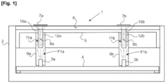
- FIG. 1 is a schematic representation of an interior lighting device of a motor vehicle according to an exemplary embodiment of the invention.
- a vehicle interior lighting device 1 essentially comprises a housing 2 housing at least one light source 3a, 3b which is mounted on an electronic control board 4 for its activation or vice versa for its deactivation.
- the electronic control card 4 is installed at the bottom of the case 2 and the light sources 3a, 3b are two in number.
- Each of the light sources 3a, 3b generates a light flux F1a, F1b and comprises for example at least one LED. It is understood here that the respective activations of the light sources 3a, 3b are preferably controlled individually by the electronic control card 4, without excluding their simultaneous individual activations.
- the box 2 has a face open to the outside which is closed off by a mask 5 preventing the emergence out of the box 2 of the light F1a, F1b generated by the light sources 3a, 3b.
- the mask 5 is covered on its face facing the outside of the box 2 by a transparent wall 6 comprising pictograms 7a, 7b visible from the outside of the box 2, in particular visible to the passengers of the vehicle.
- a transparent wall 6 comprising pictograms 7a, 7b visible from the outside of the box 2, in particular visible to the passengers of the vehicle.
- the light F1a, F1b generated by the light sources 3a, 3b is provided to emerge locally through the transparent wall 6, in its zones on which the pictograms 7a, 7b are respectively arranged.
- the transparent wall 6 on the mask 5 incorporates at least one positioning member 8a, 8b, two in number according to the illustrated embodiment.
- the positioning members 8a, 8b are each configured as a light guide, coming from the transparent wall 6 during its molding.
- Each of the positioning members 8a, 8b cooperates with a light guide 9a, 9b which extends inside the casing 2 between the mask 5 and a light source 3a, 3b.
- the positioning members 8a, 8b form with the light guides 9a, 9b which are assigned to them, a set for guiding the light F1a, F1b generated by the light sources 3a, 3b towards the pictograms 7a, 7b for their backlighting.
- each of said guide assemblies is composed of two successive light guides cooperating with each other, including a first light guide 9a, 9b extending inside the casing 2 between a light source 3a, 3b and the mask 5, and including a second light guide formed by the positioning member 8a, 8b.
- the positioning members 8a, 8b pass through the mask 5 by being nested inside respective openings 10a, 10b that the mask 5 comprises. light 3a, 3b assigned to it.
- the emerging part 11a, 11b out of the openings 10a, 10b of the positioning members 8a, 8b is arranged as a receiving member by interlocking the light guide 9a, 9b with which it cooperates.
- said emerging parts 11a, 11b of the positioning members 8a, 8b are introduced by interlocking inside a cavity 12a, 12b that includes the light guides 9a, 9b with which the positioning members 8a, 8b are respectively cooperating.
- the interlocking of the positioning members 8a, 8b inside said openings 10a, 10b provides the relative positioning between the transparent wall 6 and the mask 5, and on the other hand allows the passage through the organs positioning 8a, 8b of the light F1a, F1b coming from the light guides 9a, 9b to provide the backlighting of the pictograms 7a, 7b.
Landscapes
- Engineering & Computer Science (AREA)
- Chemical & Material Sciences (AREA)
- Combustion & Propulsion (AREA)
- Transportation (AREA)
- Mechanical Engineering (AREA)
- Physics & Mathematics (AREA)
- General Physics & Mathematics (AREA)
- Optics & Photonics (AREA)
- Arrangements Of Lighting Devices For Vehicle Interiors, Mounting And Supporting Thereof, Circuits Therefore (AREA)
Description
- L'invention relève du domaine de l'agencement des dispositifs d'éclairage intérieur d'un véhicule automobile, tel que par exemple un plafonnier ou une liseuse. L'invention concerne plus spécifiquement un tel dispositif d'éclairage utilisant au moins un guide de lumière.
- Les véhicules automobiles sont couramment équipés de dispositifs d'éclairage intérieur, comme par exemple un plafonnier ou une liseuse. De tels dispositifs d'éclairage comprennent essentiellement un boîtier logeant au moins une source lumineuse génératrice d'un flux lumineux, et au moins un dispositif optique de guidage du dit flux lumineux vers une paroi transparente à travers laquelle émerge la lumière issue du flux lumineux.
- Ladite au moins une source lumineuse est communément montée sur une carte électronique de commande qui régule son activation pour générer le flux lumineux. La carte électronique de commande est notamment montée en fond du boîtier dont un débouché est fermé par la paroi transparente. La carte électronique de commande intègre couramment un circuit de commande sélective de l'activation de ladite au moins une source lumineuse.
- Il est désormais courant que de tels dispositifs d'éclairage soient équipés d'une ou de plusieurs DEL (d'après l'acronyme de Diode ElectroLuminescente) constitutives de ladite au moins une source lumineuse. Une ou plusieurs sources lumineuses peuvent être respectivement affectées à des fonctions d'éclairage spécifiques, tel que par exemple l'éclairage de l'habitacle du véhicule et/ou le rétroéclairage d'un pictogramme.
- Plus particulièrement, les dispositifs d'éclairage intérieur d'un véhicule automobile peuvent cumuler plusieurs fonctionnalités d'éclairage distinctes. Par exemple, un même dispositif d'éclairage comme un plafonnier peut fournir un faisceau lumineux principal d'éclairage de l'habitacle, un faisceau lumineux secondaire à fonction de liseuse pour l'un au moins des passagers du véhicule, et/ou un ou plusieurs faisceaux lumineux annexes de rétroéclairage respectivement d'un ou de plusieurs pictogrammes qui sont potentiellement ménagés en surface de la paroi transparente.
- Un ou plusieurs masques sont couramment interposés entre la source lumineuse et la paroi transparente, pour faire obstacle au passage de la lumière en des zones prédéfinies de la paroi transparente. Il est courant de positionner et de fixer la paroi transparente sur le masque, qui est lui-même positionné et fixé à l'intérieur du boîtier. Un tel masque comporte au moins une ouverture pour le passage de la lumière à son travers, depuis la source lumineuse vers la paroi transparente via un dit dispositif optique. Ainsi, le faisceau lumineux en sortie du dispositif optique peut émerger à travers la paroi transparente seulement en une ou plusieurs zones sélectionnées, telles que notamment celles comportant de dits pictogrammes.
- Il est devenu fréquent que le dispositif optique comprennent au moins un guide de lumière affecté à l'acheminement de la lumière générée par au moins une source lumineuse vers la paroi transparente. Un tel guide de lumière est par exemple utilisé pour acheminer la lumière générée par la source lumineuse, depuis la carte électronique de commande vers un pictogramme ménagé en surface de la paroi transparente.
- Le guide de lumière est alors fixé sur la carte électronique de commande, et s'étend vers la paroi transparente à travers le masque via une dite ouverture qu'il comporte. La lumière générée par la source lumineuse est captée par le guide de lumière qui le traverse pour son acheminement vers la paroi transparente. La lumière traverse alors la paroi transparente pour son émergence hors du dispositif d'éclairage via la paroi transparente.
- Les passagers du véhicule disposent de divers organes de commande via lesquels ils peuvent sélectivement activer une ou plusieurs sources lumineuses du dispositif d'éclairage, selon la ou les fonctionnalités d'éclairage souhaitées, comme par exemple une fonction d'éclairage de l'habitacle, une fonction d'activation d'une liseuse et/ou une fonction de rétroéclairage d'un ou de plusieurs pictogrammes ménagés en surface de la paroi transparente.
- Tel qu'il ressort par exemple du document
FR 3 056 471-A1- (DAV - Les documents
JP2015041486 DE10341622 etUS2006152937 décrivent différents dispositifs d'éclairage avec comportant un guide de lumière guidant la lumière émise par une source de lumière. - Cependant, il est avantageux qu'un même dispositif d'éclairage intérieur d'un véhicule automobile puisse être utilisé et/ou être facilement adapté pour son installation sur divers véhicules présentant des architectures spécifiques.
- Il est alors à rechercher une simplification de l'agencement du dispositif d'éclairage, notamment en limitant la diversité et/ou le nombre de ses composants, afin de simplifier les modalités d'aménagement du dispositif d'éclairage pour son implantation sur de tels véhicules diversifiés, de limiter les éventuels surcoûts qui en résultent et/ou d'optimiser le retour sur investissement du dispositif d'éclairage.
- La présente invention s'inscrit dans un tel cadre de recherche et a pour objet un dispositif d'éclairage intérieur d'un véhicule équipé d'au moins un guide de lumière.
- L'invention a aussi pour objet un véhicule automobile équipé d'au moins un dispositif d'éclairage conforme à l'invention.
- Un dispositif d'éclairage intérieur d'un véhicule automobile conforme à l'invention, comprend un boîtier logeant :
- -) au moins une source lumineuse montée sur une carte électronique de commande,
- -) au moins un masque muni d'au moins une paroi transparente montée sur le masque via au moins un organe de positionnement de la paroi transparente sur le masque, et
- -) au moins un guide de lumière via lequel la lumière émise par la source lumineuse est apte à être acheminée vers la paroi transparente.
- Dans ce contexte, l'invention est reconnaissable en ce que ledit au moins un organe de positionnement est configuré en guide de lumière. L'organe de positionnement est en outre coopérant au moins avec un guide de lumière avec lequel il forme un ensemble de guidage de la lumière émise par la source lumineuse vers la paroi transparente. Autrement dit et selon une autre approche, la lumière émise par la source lumineuse est guidé vers la paroi transparente via ledit ensemble de guidage, qui comprend un premier guide de lumière via lequel la lumière émise par la source lumineuse est acheminée vers un deuxième guide de lumière formé par ledit organe de positionnement de la paroi transparente sur le masque.
- L'agencement de l'organe de positionnement en guide de lumière lui confère une double fonction. Une première fonction est une fonction de positionnement de la paroi transparente sur le masque. Une deuxième fonction est d'acheminer au moins en partie la lumière émise par la source lumineuse vers la paroi transparente. Le cumul de ces deux fonctions par l'organe de positionnement permet de simplifier l'agencement du dispositif et/ou de réduire le nombre de ses composants.
- Plus particulièrement selon une forme de réalisation, l'organe de positionnement est agencé en doigt d'emboîtement à l'intérieur d'une ouverture ménagée à travers le masque. Une partie émergente de l'organe de positionnement hors de ladite ouverture en direction de la source lumineuse est coopérante par emboîtement avec le guide de lumière qui s'étend entre le masque et la source lumineuse.
- Plus spécifiquement selon une forme de réalisation, le doigt constitutif de l'organe de positionnement est introduit en emboîtement glissant à travers l'ouverture que comporte le masque, et le guide de lumière comporte une cavité de réception par emboîtement d'une partie émergente du doigt.
- De préférence, le doigt constitutif de l'organe de positionnement présente une section transversale constante, la notion "transversal" étant bien entendu comprise comme orientée perpendiculairement à l'orientation principale d'extension du doigt depuis la paroi transparente vers la source lumineuse. Le doigt est emboîté à l'intérieur de l'ouverture que comporte le masque et s'étend à section constante hors du masque vers la source lumineuse pour sa jonction par emboîtement à l'intérieur du guide de lumière.
- Selon une forme de réalisation, l'organe de positionnement est intégré à la paroi transparente en étant issu de sa matière.
- De préférence, la matière à partir de laquelle sont conjointement formés la paroi transparente et l'organe de positionnement est un polymère thermoplastique. Ledit polymère thermoplastique est plus spécifiquement une forme laiteuse d'un poly-méthacrylate de méthyle.
- L'invention est notamment avantageusement applicable au rétroéclairage d'un pictogramme dont la paroi transparente est munie. Plus particulièrement selon une forme de réalisation, la paroi transparente comporte au moins un pictogramme lumineux dont le rétroéclairage est fourni par le guide de lumière via l'organe de positionnement.
- Par exemple, le pictogramme est un visuel représentant l'état en position d'ouverture d'au moins un ouvrant d'un véhicule automobile.
- Selon une forme de réalisation, le dispositif d'éclairage est agencé en plafonnier.
- Selon une autre forme de réalisation, le dispositif d'éclairage est agencé en liseuse.
- Il est compris ici que le dispositif d'éclairage est par exemple agencé en plafonnier, par exemple encore en liseuse, ou par exemple encore en plafonnier dont au moins une zone d'éclairage est agencé en liseuse.
- L'invention a aussi pour objet un véhicule automobile reconnaissable en ce qu'il est équipé d'au moins un dispositif d'éclairage conforme à l'invention.
- L'invention sera mieux comprise à la lecture de la description détaillée qui suit d'un exemple de réalisation de la présente invention, en relation avec la figure suivante :
[Fig. 1 ] Lafigure 1 est une représentation schématique d'un dispositif d'éclairage intérieur d'un véhicule automobile selon un exemple de réalisation de l'invention. - La figure unique et sa description détaillée non limitative, expose l'invention selon des modalités particulières qui ne sont pas restrictives quant à la portée de l'invention telle que définie par les revendications. La figure et sa description détaillée d'un exemple de réalisation de l'invention peut servir à mieux la définir, si besoin en relation avec la description générale qui vient d'en être faite.
- Sur la
figure 1 , un dispositif d'éclairage 1 intérieur du véhicule comprend essentiellement un boîtier 2 logeant au moins une source lumineuse 3a, 3b qui est montée sur une carte électronique de commande 4 de son activation ou inversement de sa désactivation. Selon l'exemple illustré, la carte électronique de commande 4 est installée en fond du boîtier 2 et les sources lumineuses 3a, 3b sont au nombre de deux. Chacune des sources lumineuses 3a, 3b est génératrice d'un flux lumineux F1a, F1b et comprend par exemple au moins une DEL. Il est compris ici que les activations respectives des sources lumineuses 3a, 3b sont de préférence contrôlées individuellement par la carte électronique de commande 4, sans exclure leurs activations individuelles simultanées. - Le boîtier 2 présente une face ouverte vers l'extérieur qui est obturée par un masque 5 faisant obstacle à l'émergence hors du boîtier 2 de la lumière F1a, F1b générée par les sources lumineuses 3a, 3b. Le masque 5 est couvert à sa face orientée vers l'extérieur du boîtier 2 par une paroi transparente 6 comportant des pictogrammes 7a, 7b visibles depuis l'extérieur du boîtier 2, notamment visibles par les passagers du véhicule. Pour rétroéclairer les pictogrammes 7a, 7b, la lumière F1a, F1b générée par les sources lumineuses 3a, 3b est prévue d'émerger localement à travers la paroi transparente 6, dans ses zones sur lesquelles les pictogrammes 7a, 7b sont respectivement ménagés.
- Pour positionner rigoureusement la paroi transparente 6 sur le masque 5, celle-ci intègre au moins un organe de positionnement 8a, 8b, au nombre de deux selon l'exemple de réalisation illustré. Les organes de positionnement 8a, 8b sont chacun configurés en guide de lumière, en étant issus de la paroi transparente 6 lors de son moulage.
- Chacun des organes de positionnement 8a, 8b coopère avec un guide de lumière 9a, 9b qui s'étend à l'intérieur du boîtier 2 entre le masque 5 et une source lumineuse 3a, 3b. Les organes de positionnement 8a, 8b forment avec les guide de lumière 9a, 9b qui leur sont affectés, un ensemble de guidage de la lumière F1a, F1b générée par les sources lumineuses 3a, 3b vers les pictogrammes 7a, 7b pour leur rétroéclairage. Ainsi, chacun desdits ensembles de guidage est composé de deux guides de lumière successifs coopérant entre eux, dont un premier guide de lumière 9a, 9b s'étendant à l'intérieur du boîtier 2 entre une source lumineuse 3a, 3b et le masque 5, et dont un deuxième guide de lumière formé par l'organe de positionnement 8a, 8b.
- Pour autoriser l'émergence de la lumière F1a, F1b à travers la paroi transparente 6 via les ensembles de guidage 3a, 9a et 3b, 9b de la lumière F1a, F1b, les organes de positionnement 8a, 8b traversent le masque 5 en étant emboîtés à l'intérieur d'ouvertures 10a, 10b respectives que comporte le masque 5. Chacun des organes de positionnement 8a, 8b est agencé en doigt qui émerge hors de l'ouverture 10a, 10b qui le reçoit, en s'étendant vers la source lumineuse 3a, 3b qui lui est affectée.
- La partie émergente 11a, 11b hors des ouvertures 10a, 10b des organes de positionnement 8a, 8b est agencée en organe de réception par emboîtement du guide de lumière 9a, 9b avec lequel il est coopérant. A cet effet, Lesdites parties émergentes 11a, 11b des organes de positionnement 8a, 8b sont introduites par emboîtement à l'intérieur d'une cavité 12a, 12b que comporte les guides de lumière 9a, 9b avec lesquels les organes de positionnement 8a, 8b sont respectivement coopérant.
- L'emboîtement des organes de positionnement 8a, 8b à l'intérieur desdites ouvertures 10a, 10b, d'une part procure le positionnement relatif entre la paroi transparente 6 et le masque 5, et d'autre part autorise le passage à travers les organes de positionnement 8a, 8b de la lumière F1a, F1b en provenance des guides de lumière 9a, 9b pour procurer le rétroéclairage des pictogrammes 7a, 7b.
Claims (9)
- Dispositif d'éclairage (1) intérieur d'un véhicule automobile, comprenant un boîtier (2) logeant au moins une source lumineuse (3a, 3b) montée sur une carte électronique de commande (4), au moins un masque (5) muni d'au moins une paroi transparente (6) montée sur le masque (5) via au moins un organe de positionnement (8a, 8b) de la paroi transparente (6) sur le masque (5), et au moins un guide de lumière (9a, 9b) via lequel la lumière (F1a, F1b) émise par la source lumineuse (3a, 3b) est apte à être acheminée vers la paroi transparente (6), ledit au moins un organe de positionnement (8a, 8b) étant configuré en guide de lumière, caractérisé en ce que l'organe de positionnement (8a, 8b) est coopérant au moins avec un guide de lumière (9a, 9b) avec lequel il forme un ensemble de guidage de la lumière (F1a, F1b) émise par la source lumineuse (3a, 3b) vers la paroi transparente (6).
- Dispositif d'éclairage (1) selon la revendication 1, caractérisé en ce que l'organe de positionnement (8a, 8b) est agencé en doigt d'emboîtement à l'intérieur d'une ouverture (10a, 10b) ménagée à travers le masque (5), une partie émergente (11a, 11b) de l'organe de positionnement (8a, 8b) hors de ladite ouverture (10a, 10b) en direction de la source lumineuse (3a, 3b) coopérant par emboîtement avec le guide de lumière (9a, 9b) qui s'étend entre le masque (5) et la source lumineuse (3a, 3b).
- Dispositif d'éclairage (1) selon l'une quelconque des revendications 1 à 2, caractérisé en ce que l'organe de positionnement (8a, 8b) est intégré à la paroi transparente (6) en étant issu de sa matière.
- Dispositif d'éclairage (1) selon la revendication 3, caractérisé en ce que la matière à partir de laquelle sont conjointement formés la paroi transparente (6) et l'organe de positionnement (8a, 8b) est un polymère thermoplastique.
- Dispositif d'éclairage (1) selon la revendication 4, caractérisé en ce que la paroi transparente (6) comporte au moins un pictogramme (7a, 7b) lumineux dont le rétroéclairage est fourni par le guide de lumière (9a, 9b) via l'organe de positionnement (8a, 8b).
- Dispositif d'éclairage (1) selon la revendication 5, caractérisé en ce que le pictogramme (7a, 7b) est un visuel représentant l'état en position d'ouverture d'au moins un ouvrant d'un véhicule automobile.
- Dispositif d'éclairage (1) selon l'une quelconque des revendications 1 à 6, caractérisé en ce que le dispositif d'éclairage (1) est agencé un plafonnier.
- Dispositif d'éclairage (1) selon l'une quelconque des revendications 1 à 6, caractérisé en ce que le dispositif d'éclairage (1) est agencé en liseuse.
- Véhicule automobile caractérisé en ce qu'il est équipé d'au moins un dispositif d'éclairage (1) selon l'une quelconque des revendications 1 à 8.
Applications Claiming Priority (2)
| Application Number | Priority Date | Filing Date | Title |
|---|---|---|---|
| FR1902971A FR3093967B1 (fr) | 2019-03-22 | 2019-03-22 | Dispositif d'éclairage intérieur d'un véhicule automobile, comprenant une paroi transparente pourvue d'un organe de positionnement sur le dispositif qui est configuré en guide de lumière |
| PCT/FR2020/050334 WO2020193891A1 (fr) | 2019-03-22 | 2020-02-21 | Dispositif d'éclairage intérieur d'un véhicule automobile, comprenant une paroi transparente pourvue d'un organe de positionnement sur le dispositif qui est configuré en guide de lumière |
Publications (2)
| Publication Number | Publication Date |
|---|---|
| EP3941772A1 EP3941772A1 (fr) | 2022-01-26 |
| EP3941772B1 true EP3941772B1 (fr) | 2023-08-23 |
Family
ID=67742594
Family Applications (1)
| Application Number | Title | Priority Date | Filing Date |
|---|---|---|---|
| EP20713706.8A Active EP3941772B1 (fr) | 2019-03-22 | 2020-02-21 | Dispositif d'éclairage intérieur d'un véhicule automobile, comprenant une paroi transparente pourvue d'un organe de positionnement sur le dispositif qui est configuré en guide de lumière |
Country Status (6)
| Country | Link |
|---|---|
| EP (1) | EP3941772B1 (fr) |
| CN (1) | CN113613932A (fr) |
| ES (1) | ES2956389T3 (fr) |
| FR (1) | FR3093967B1 (fr) |
| MA (1) | MA62182B1 (fr) |
| WO (1) | WO2020193891A1 (fr) |
Families Citing this family (1)
| Publication number | Priority date | Publication date | Assignee | Title |
|---|---|---|---|---|
| EP4631790A1 (fr) * | 2024-04-11 | 2025-10-15 | Hella Autotechnik Nova s.r.o. | Dispositif d'éclairage de véhicule pour transférer de la lumière à travers un composant de véhicule, ensemble pour créer le dispositif et composant de véhicule avec le dispositif |
Family Cites Families (15)
| Publication number | Priority date | Publication date | Assignee | Title |
|---|---|---|---|---|
| DE10341622B3 (de) * | 2003-09-10 | 2005-08-18 | Preh Gmbh | Anzeigeeinrichtung mit kombiniertem Lichtleiter |
| DE102004029248B4 (de) * | 2004-06-17 | 2008-12-11 | Lisa Dräxlmaier GmbH | Beleuchtungssystem für Anzeigen, insbesondere in Fahrzeugen sowie Abdeckungsbauteil für derartiges Beleuchtungssystem |
| FR2889767B1 (fr) * | 2005-08-11 | 2011-05-13 | Valeo Systemes Thermiques | Retro eclairage d'un bouton de commande avec guide lumiere. |
| FR2965227B1 (fr) * | 2010-09-23 | 2013-03-08 | Continental Automotive France | Dispositif lumineux pour vehicule et poignee de porte de vehicule comprenant un tel dispositif |
| JP5802103B2 (ja) * | 2011-10-13 | 2015-10-28 | トヨタ紡織株式会社 | 車両用照明装置 |
| MX2014013545A (es) * | 2012-05-09 | 2015-02-12 | Ts Tech Co Ltd | Dispositivo de emision de luz. |
| CZ306672B6 (cs) * | 2012-08-22 | 2017-05-03 | Varroc Lighting Systems, s.r.o. | Svítilna motorového vozidla |
| FR3007102B1 (fr) * | 2013-06-14 | 2018-04-20 | Automotive Lighting Rear Lamps France | Module d'eclairage pour automobiles a homogeneite de lumiere a evolution continue |
| JP5372291B1 (ja) * | 2013-08-21 | 2013-12-18 | 株式会社ジュナック | 車輌用発光エンブレム |
| US9302587B2 (en) * | 2014-04-25 | 2016-04-05 | Continental Automotive Systems, Inc. | Instrument cluster including telltale illumination using a light guide |
| FR3049686B1 (fr) * | 2016-03-29 | 2022-07-01 | Peugeot Citroen Automobiles Sa | Dispositif d’eclairage comportant un boitier dote d’un fut de reception pour un troncon cylindrique d’un guide de lumiere. |
| FR3051162B1 (fr) * | 2016-05-11 | 2018-05-25 | Peugeot Citroen Automobiles Sa | Equipement de signalisation arriere a multifonction d'eclairage |
| FR3056471B1 (fr) | 2016-09-28 | 2022-04-15 | Dav | Interface pour vehicule automobile et procede d'eclairage |
| FR3064560B1 (fr) * | 2017-03-31 | 2020-10-16 | Valeo Vision | Module d'eclairage interieur pour vehicule automobile |
| FR3064531B1 (fr) * | 2017-03-31 | 2019-04-05 | Saint-Gobain Glass France | Vitrage eclairant. |
-
2019
- 2019-03-22 FR FR1902971A patent/FR3093967B1/fr not_active Expired - Fee Related
-
2020
- 2020-02-21 CN CN202080023088.2A patent/CN113613932A/zh active Pending
- 2020-02-21 WO PCT/FR2020/050334 patent/WO2020193891A1/fr not_active Ceased
- 2020-02-21 MA MA62182A patent/MA62182B1/fr unknown
- 2020-02-21 EP EP20713706.8A patent/EP3941772B1/fr active Active
- 2020-02-21 ES ES20713706T patent/ES2956389T3/es active Active
Also Published As
| Publication number | Publication date |
|---|---|
| WO2020193891A1 (fr) | 2020-10-01 |
| MA62182B1 (fr) | 2023-09-27 |
| EP3941772A1 (fr) | 2022-01-26 |
| CN113613932A (zh) | 2021-11-05 |
| ES2956389T3 (es) | 2023-12-20 |
| FR3093967B1 (fr) | 2021-02-26 |
| FR3093967A1 (fr) | 2020-09-25 |
Similar Documents
| Publication | Publication Date | Title |
|---|---|---|
| US6594417B1 (en) | Waveguide assembly for laterally-directed illumination in a vehicle lighting system | |
| CN103282235B (zh) | 车辆用照明装置 | |
| CN110337384B (zh) | 用于内部装饰件的照明设备 | |
| MX2007005225A (es) | Ensamble de lampara de cortesia interior de vehiculo. | |
| US20130242603A1 (en) | Lighting device | |
| EP3904159A1 (fr) | Dispositif de miroir pour véhicule et dispositif d'affichage de miroir pouvant être éclairé | |
| KR101804311B1 (ko) | 백라이트 유닛 | |
| CN112601678A (zh) | 用于机动车的照明装置 | |
| US20170129386A1 (en) | Cross shut gap lighting source | |
| JP2016134326A (ja) | 照明装置 | |
| JP2009143409A (ja) | 車両用室内照明装置 | |
| CN100469619C (zh) | 照明组件 | |
| FR3079282A1 (fr) | Agencement pour vehicule automobile comprenant un element de carrosserie et un dispositif d’eclairage et/ou de signalisation implante dans ledit element de carrosserie | |
| EP3941772B1 (fr) | Dispositif d'éclairage intérieur d'un véhicule automobile, comprenant une paroi transparente pourvue d'un organe de positionnement sur le dispositif qui est configuré en guide de lumière | |
| FR3023530A1 (fr) | Module formant un element de carrosserie pour vehicule automobile participant a l'esthetique exterieure du vehicule | |
| US11257404B2 (en) | Motor vehicle control device and method for manufacturing a motor vehicle control device | |
| JP4858364B2 (ja) | 車両用室内照明システム | |
| JP2008174083A (ja) | 車両用灯具、車両用灯具を備える車両用アウトサイドミラー装置 | |
| FR2994548A1 (fr) | Structure de feux pour vehicule automobile | |
| JP2021017179A (ja) | アンビエントライト | |
| JP2014107246A (ja) | 車両用灯具 | |
| JP2009078794A (ja) | 車両用室内照明装置 | |
| CN112739951B (zh) | 光学模块,尤其在机动车的照明装置中使用的光学模块 | |
| US10690313B2 (en) | Automotive lighting unit | |
| JP5407190B2 (ja) | 車両用ドアトリム照明装置 |
Legal Events
| Date | Code | Title | Description |
|---|---|---|---|
| STAA | Information on the status of an ep patent application or granted ep patent |
Free format text: STATUS: UNKNOWN |
|
| STAA | Information on the status of an ep patent application or granted ep patent |
Free format text: STATUS: THE INTERNATIONAL PUBLICATION HAS BEEN MADE |
|
| PUAI | Public reference made under article 153(3) epc to a published international application that has entered the european phase |
Free format text: ORIGINAL CODE: 0009012 |
|
| STAA | Information on the status of an ep patent application or granted ep patent |
Free format text: STATUS: REQUEST FOR EXAMINATION WAS MADE |
|
| 17P | Request for examination filed |
Effective date: 20211011 |
|
| AK | Designated contracting states |
Kind code of ref document: A1 Designated state(s): AL AT BE BG CH CY CZ DE DK EE ES FI FR GB GR HR HU IE IS IT LI LT LU LV MC MK MT NL NO PL PT RO RS SE SI SK SM TR |
|
| DAX | Request for extension of the european patent (deleted) | ||
| RAV | Requested validation state of the european patent: fee paid |
Extension state: MA Effective date: 20211011 |
|
| GRAP | Despatch of communication of intention to grant a patent |
Free format text: ORIGINAL CODE: EPIDOSNIGR1 |
|
| STAA | Information on the status of an ep patent application or granted ep patent |
Free format text: STATUS: GRANT OF PATENT IS INTENDED |
|
| INTG | Intention to grant announced |
Effective date: 20230414 |
|
| GRAS | Grant fee paid |
Free format text: ORIGINAL CODE: EPIDOSNIGR3 |
|
| GRAA | (expected) grant |
Free format text: ORIGINAL CODE: 0009210 |
|
| STAA | Information on the status of an ep patent application or granted ep patent |
Free format text: STATUS: THE PATENT HAS BEEN GRANTED |
|
| AK | Designated contracting states |
Kind code of ref document: B1 Designated state(s): AL AT BE BG CH CY CZ DE DK EE ES FI FR GB GR HR HU IE IS IT LI LT LU LV MC MK MT NL NO PL PT RO RS SE SI SK SM TR |
|
| REG | Reference to a national code |
Ref country code: GB Ref legal event code: FG4D Free format text: NOT ENGLISH |
|
| REG | Reference to a national code |
Ref country code: CH Ref legal event code: EP |
|
| REG | Reference to a national code |
Ref country code: IE Ref legal event code: FG4D Free format text: LANGUAGE OF EP DOCUMENT: FRENCH |
|
| REG | Reference to a national code |
Ref country code: DE Ref legal event code: R084 Ref document number: 602020016253 Country of ref document: DE Ref country code: DE Ref legal event code: R096 Ref document number: 602020016253 Country of ref document: DE |
|
| REG | Reference to a national code |
Ref country code: MA Ref legal event code: VAGR Ref document number: 62182 Country of ref document: MA Kind code of ref document: B1 |
|
| REG | Reference to a national code |
Ref country code: GB Ref legal event code: 746 Effective date: 20230929 |
|
| REG | Reference to a national code |
Ref country code: LT Ref legal event code: MG9D |
|
| RAP4 | Party data changed (patent owner data changed or rights of a patent transferred) |
Owner name: STELLANTIS AUTO SAS |
|
| REG | Reference to a national code |
Ref country code: ES Ref legal event code: FG2A Ref document number: 2956389 Country of ref document: ES Kind code of ref document: T3 Effective date: 20231220 |
|
| REG | Reference to a national code |
Ref country code: NL Ref legal event code: MP Effective date: 20230823 |
|
| REG | Reference to a national code |
Ref country code: AT Ref legal event code: MK05 Ref document number: 1602198 Country of ref document: AT Kind code of ref document: T Effective date: 20230823 |
|
| PG25 | Lapsed in a contracting state [announced via postgrant information from national office to epo] |
Ref country code: GR Free format text: LAPSE BECAUSE OF FAILURE TO SUBMIT A TRANSLATION OF THE DESCRIPTION OR TO PAY THE FEE WITHIN THE PRESCRIBED TIME-LIMIT Effective date: 20231124 |
|
| PG25 | Lapsed in a contracting state [announced via postgrant information from national office to epo] |
Ref country code: IS Free format text: LAPSE BECAUSE OF FAILURE TO SUBMIT A TRANSLATION OF THE DESCRIPTION OR TO PAY THE FEE WITHIN THE PRESCRIBED TIME-LIMIT Effective date: 20231223 |
|
| PG25 | Lapsed in a contracting state [announced via postgrant information from national office to epo] |
Ref country code: SE Free format text: LAPSE BECAUSE OF FAILURE TO SUBMIT A TRANSLATION OF THE DESCRIPTION OR TO PAY THE FEE WITHIN THE PRESCRIBED TIME-LIMIT Effective date: 20230823 Ref country code: RS Free format text: LAPSE BECAUSE OF FAILURE TO SUBMIT A TRANSLATION OF THE DESCRIPTION OR TO PAY THE FEE WITHIN THE PRESCRIBED TIME-LIMIT Effective date: 20230823 Ref country code: PT Free format text: LAPSE BECAUSE OF FAILURE TO SUBMIT A TRANSLATION OF THE DESCRIPTION OR TO PAY THE FEE WITHIN THE PRESCRIBED TIME-LIMIT Effective date: 20231226 Ref country code: NO Free format text: LAPSE BECAUSE OF FAILURE TO SUBMIT A TRANSLATION OF THE DESCRIPTION OR TO PAY THE FEE WITHIN THE PRESCRIBED TIME-LIMIT Effective date: 20231123 Ref country code: NL Free format text: LAPSE BECAUSE OF FAILURE TO SUBMIT A TRANSLATION OF THE DESCRIPTION OR TO PAY THE FEE WITHIN THE PRESCRIBED TIME-LIMIT Effective date: 20230823 Ref country code: LV Free format text: LAPSE BECAUSE OF FAILURE TO SUBMIT A TRANSLATION OF THE DESCRIPTION OR TO PAY THE FEE WITHIN THE PRESCRIBED TIME-LIMIT Effective date: 20230823 Ref country code: LT Free format text: LAPSE BECAUSE OF FAILURE TO SUBMIT A TRANSLATION OF THE DESCRIPTION OR TO PAY THE FEE WITHIN THE PRESCRIBED TIME-LIMIT Effective date: 20230823 Ref country code: IS Free format text: LAPSE BECAUSE OF FAILURE TO SUBMIT A TRANSLATION OF THE DESCRIPTION OR TO PAY THE FEE WITHIN THE PRESCRIBED TIME-LIMIT Effective date: 20231223 Ref country code: HR Free format text: LAPSE BECAUSE OF FAILURE TO SUBMIT A TRANSLATION OF THE DESCRIPTION OR TO PAY THE FEE WITHIN THE PRESCRIBED TIME-LIMIT Effective date: 20230823 Ref country code: GR Free format text: LAPSE BECAUSE OF FAILURE TO SUBMIT A TRANSLATION OF THE DESCRIPTION OR TO PAY THE FEE WITHIN THE PRESCRIBED TIME-LIMIT Effective date: 20231124 Ref country code: FI Free format text: LAPSE BECAUSE OF FAILURE TO SUBMIT A TRANSLATION OF THE DESCRIPTION OR TO PAY THE FEE WITHIN THE PRESCRIBED TIME-LIMIT Effective date: 20230823 Ref country code: AT Free format text: LAPSE BECAUSE OF FAILURE TO SUBMIT A TRANSLATION OF THE DESCRIPTION OR TO PAY THE FEE WITHIN THE PRESCRIBED TIME-LIMIT Effective date: 20230823 |
|
| PG25 | Lapsed in a contracting state [announced via postgrant information from national office to epo] |
Ref country code: PL Free format text: LAPSE BECAUSE OF FAILURE TO SUBMIT A TRANSLATION OF THE DESCRIPTION OR TO PAY THE FEE WITHIN THE PRESCRIBED TIME-LIMIT Effective date: 20230823 |
|
| REG | Reference to a national code |
Ref country code: DE Ref legal event code: R081 Ref document number: 602020016253 Country of ref document: DE Owner name: STELLANTIS AUTO SAS, FR Free format text: FORMER OWNER: PSA AUTOMOBILES SA, POISSY, FR |
|
| PG25 | Lapsed in a contracting state [announced via postgrant information from national office to epo] |
Ref country code: SM Free format text: LAPSE BECAUSE OF FAILURE TO SUBMIT A TRANSLATION OF THE DESCRIPTION OR TO PAY THE FEE WITHIN THE PRESCRIBED TIME-LIMIT Effective date: 20230823 Ref country code: RO Free format text: LAPSE BECAUSE OF FAILURE TO SUBMIT A TRANSLATION OF THE DESCRIPTION OR TO PAY THE FEE WITHIN THE PRESCRIBED TIME-LIMIT Effective date: 20230823 Ref country code: EE Free format text: LAPSE BECAUSE OF FAILURE TO SUBMIT A TRANSLATION OF THE DESCRIPTION OR TO PAY THE FEE WITHIN THE PRESCRIBED TIME-LIMIT Effective date: 20230823 Ref country code: DK Free format text: LAPSE BECAUSE OF FAILURE TO SUBMIT A TRANSLATION OF THE DESCRIPTION OR TO PAY THE FEE WITHIN THE PRESCRIBED TIME-LIMIT Effective date: 20230823 Ref country code: CZ Free format text: LAPSE BECAUSE OF FAILURE TO SUBMIT A TRANSLATION OF THE DESCRIPTION OR TO PAY THE FEE WITHIN THE PRESCRIBED TIME-LIMIT Effective date: 20230823 Ref country code: SK Free format text: LAPSE BECAUSE OF FAILURE TO SUBMIT A TRANSLATION OF THE DESCRIPTION OR TO PAY THE FEE WITHIN THE PRESCRIBED TIME-LIMIT Effective date: 20230823 |
|
| REG | Reference to a national code |
Ref country code: ES Ref legal event code: GC2A Effective date: 20240425 |
|
| REG | Reference to a national code |
Ref country code: DE Ref legal event code: R097 Ref document number: 602020016253 Country of ref document: DE |
|
| PLBE | No opposition filed within time limit |
Free format text: ORIGINAL CODE: 0009261 |
|
| STAA | Information on the status of an ep patent application or granted ep patent |
Free format text: STATUS: NO OPPOSITION FILED WITHIN TIME LIMIT |
|
| 26N | No opposition filed |
Effective date: 20240524 |
|
| PG25 | Lapsed in a contracting state [announced via postgrant information from national office to epo] |
Ref country code: SI Free format text: LAPSE BECAUSE OF FAILURE TO SUBMIT A TRANSLATION OF THE DESCRIPTION OR TO PAY THE FEE WITHIN THE PRESCRIBED TIME-LIMIT Effective date: 20230823 |
|
| PG25 | Lapsed in a contracting state [announced via postgrant information from national office to epo] |
Ref country code: MC Free format text: LAPSE BECAUSE OF FAILURE TO SUBMIT A TRANSLATION OF THE DESCRIPTION OR TO PAY THE FEE WITHIN THE PRESCRIBED TIME-LIMIT Effective date: 20230823 |
|
| REG | Reference to a national code |
Ref country code: CH Ref legal event code: PL |
|
| PG25 | Lapsed in a contracting state [announced via postgrant information from national office to epo] |
Ref country code: LU Free format text: LAPSE BECAUSE OF NON-PAYMENT OF DUE FEES Effective date: 20240221 |
|
| PG25 | Lapsed in a contracting state [announced via postgrant information from national office to epo] |
Ref country code: CH Free format text: LAPSE BECAUSE OF NON-PAYMENT OF DUE FEES Effective date: 20240229 |
|
| PG25 | Lapsed in a contracting state [announced via postgrant information from national office to epo] |
Ref country code: LU Free format text: LAPSE BECAUSE OF NON-PAYMENT OF DUE FEES Effective date: 20240221 Ref country code: CH Free format text: LAPSE BECAUSE OF NON-PAYMENT OF DUE FEES Effective date: 20240229 |
|
| PG25 | Lapsed in a contracting state [announced via postgrant information from national office to epo] |
Ref country code: BG Free format text: LAPSE BECAUSE OF FAILURE TO SUBMIT A TRANSLATION OF THE DESCRIPTION OR TO PAY THE FEE WITHIN THE PRESCRIBED TIME-LIMIT Effective date: 20230823 |
|
| PG25 | Lapsed in a contracting state [announced via postgrant information from national office to epo] |
Ref country code: BG Free format text: LAPSE BECAUSE OF FAILURE TO SUBMIT A TRANSLATION OF THE DESCRIPTION OR TO PAY THE FEE WITHIN THE PRESCRIBED TIME-LIMIT Effective date: 20230823 |
|
| REG | Reference to a national code |
Ref country code: BE Ref legal event code: MM Effective date: 20240229 |
|
| PG25 | Lapsed in a contracting state [announced via postgrant information from national office to epo] |
Ref country code: BE Free format text: LAPSE BECAUSE OF NON-PAYMENT OF DUE FEES Effective date: 20240229 |
|
| PG25 | Lapsed in a contracting state [announced via postgrant information from national office to epo] |
Ref country code: IE Free format text: LAPSE BECAUSE OF NON-PAYMENT OF DUE FEES Effective date: 20240221 |
|
| PG25 | Lapsed in a contracting state [announced via postgrant information from national office to epo] |
Ref country code: IE Free format text: LAPSE BECAUSE OF NON-PAYMENT OF DUE FEES Effective date: 20240221 Ref country code: BE Free format text: LAPSE BECAUSE OF NON-PAYMENT OF DUE FEES Effective date: 20240229 |
|
| PG25 | Lapsed in a contracting state [announced via postgrant information from national office to epo] |
Ref country code: CY Free format text: LAPSE BECAUSE OF FAILURE TO SUBMIT A TRANSLATION OF THE DESCRIPTION OR TO PAY THE FEE WITHIN THE PRESCRIBED TIME-LIMIT; INVALID AB INITIO Effective date: 20200221 |
|
| PG25 | Lapsed in a contracting state [announced via postgrant information from national office to epo] |
Ref country code: HU Free format text: LAPSE BECAUSE OF FAILURE TO SUBMIT A TRANSLATION OF THE DESCRIPTION OR TO PAY THE FEE WITHIN THE PRESCRIBED TIME-LIMIT; INVALID AB INITIO Effective date: 20200221 |
|
| VSFP | Annual fee paid to validation state [announced via postgrant information from national office to epo] |
Ref country code: MA Payment date: 20240201 Year of fee payment: 5 |
|
| VSFP | Annual fee paid to validation state [announced via postgrant information from national office to epo] |
Ref country code: MA Payment date: 20250218 Year of fee payment: 6 |
|
| PG25 | Lapsed in a contracting state [announced via postgrant information from national office to epo] |
Ref country code: TR Free format text: LAPSE BECAUSE OF FAILURE TO SUBMIT A TRANSLATION OF THE DESCRIPTION OR TO PAY THE FEE WITHIN THE PRESCRIBED TIME-LIMIT Effective date: 20230823 |
|
| PGFP | Annual fee paid to national office [announced via postgrant information from national office to epo] |
Ref country code: GB Payment date: 20260121 Year of fee payment: 7 |
|
| PGFP | Annual fee paid to national office [announced via postgrant information from national office to epo] |
Ref country code: ES Payment date: 20260302 Year of fee payment: 7 |
|
| PGFP | Annual fee paid to national office [announced via postgrant information from national office to epo] |
Ref country code: DE Payment date: 20260121 Year of fee payment: 7 |
|
| PGFP | Annual fee paid to national office [announced via postgrant information from national office to epo] |
Ref country code: IT Payment date: 20260121 Year of fee payment: 7 |
|
| VSFP | Annual fee paid to validation state [announced via postgrant information from national office to epo] |
Ref country code: MA Payment date: 20260216 Year of fee payment: 7 |
|
| PGFP | Annual fee paid to national office [announced via postgrant information from national office to epo] |
Ref country code: FR Payment date: 20260121 Year of fee payment: 7 |