EP3940904A1 - Seal device - Google Patents
Seal device Download PDFInfo
- Publication number
- EP3940904A1 EP3940904A1 EP21191260.5A EP21191260A EP3940904A1 EP 3940904 A1 EP3940904 A1 EP 3940904A1 EP 21191260 A EP21191260 A EP 21191260A EP 3940904 A1 EP3940904 A1 EP 3940904A1
- Authority
- EP
- European Patent Office
- Prior art keywords
- sealing
- section
- sealing device
- unit
- sealing unit
- Prior art date
- Legal status (The legal status is an assumption and is not a legal conclusion. Google has not performed a legal analysis and makes no representation as to the accuracy of the status listed.)
- Withdrawn
Links
Images


Classifications
-
- H—ELECTRICITY
- H02—GENERATION; CONVERSION OR DISTRIBUTION OF ELECTRIC POWER
- H02G—INSTALLATION OF ELECTRIC CABLES OR LINES, OR OF COMBINED OPTICAL AND ELECTRIC CABLES OR LINES
- H02G15/00—Cable fittings
- H02G15/013—Sealing means for cable inlets
-
- H—ELECTRICITY
- H02—GENERATION; CONVERSION OR DISTRIBUTION OF ELECTRIC POWER
- H02G—INSTALLATION OF ELECTRIC CABLES OR LINES, OR OF COMBINED OPTICAL AND ELECTRIC CABLES OR LINES
- H02G3/00—Installations of electric cables or lines or protective tubing therefor in or on buildings, equivalent structures or vehicles
- H02G3/02—Details
- H02G3/08—Distribution boxes; Connection or junction boxes
- H02G3/081—Bases, casings or covers
- H02G3/083—Inlets
- H02G3/085—Inlets including knock-out or tear-out sections
-
- H—ELECTRICITY
- H02—GENERATION; CONVERSION OR DISTRIBUTION OF ELECTRIC POWER
- H02G—INSTALLATION OF ELECTRIC CABLES OR LINES, OR OF COMBINED OPTICAL AND ELECTRIC CABLES OR LINES
- H02G3/00—Installations of electric cables or lines or protective tubing therefor in or on buildings, equivalent structures or vehicles
- H02G3/22—Installations of cables or lines through walls, floors or ceilings, e.g. into buildings
Definitions
- the invention relates to a sealing device according to the preamble of claim 1 and a method for sealing at least one elongate object relative to a sealing panel according to the preamble of claim 15.
- a sealing device with a sealing unit which has a sealing element with stepped areas with different diameters and a through-opening for the passage of a cable.
- the sealing unit is formed from a thermoplastic such as styrene ethylene butylene styrene (SEBS) or an elastomer such as nitrile butadiene rubber.
- SEBS styrene ethylene butylene styrene
- the sealing unit is fastened with its base body to a frame element consisting of two frame parts by means of a press fit.
- EP 1 643 604 A1 a gel body with a gel mass and a skin arranged on a top and bottom side of the gel mass, the skin being firmly connected to the gel mass.
- the skin is intended to contribute to emergence and/or dragging of the gel mass to prevent an elongate object from being pierced through the skin and the gel mass via the top and bottom of the gel mass.
- a spout acting as a sealing unit for passing through an elongate object is known, the ends of which are designed in the form of a truncated cone shell with respect to a main extension direction of the sealing unit.
- the object of the invention consists in particular in providing a generic sealing device with improved properties with regard to assembly.
- the object is achieved according to the invention by the features of claims 1 and 15, while advantageous configurations and developments of the invention can be found in the dependent claims.
- the invention is based on a sealing device for passing through and sealing an elongate object, with at least one sealing unit which is intended to completely enclose the object in the circumferential direction at least in sections in an assembled state, and which has at least one sealing section which is intended for this purpose , to contact the object in the mounted state and to seal it by means of an intrinsic prestress.
- the sealing section has an at least essentially constant inner diameter (18a, 18b, 18c, 18d, 18e) over at least a large part of its length in at least one dismantled state.
- assembly can advantageously be simplified.
- a time-saving assembly process can advantageously be made possible.
- a low-cost configuration can be achieved.
- a simplification of assembly can be achieved due to an advantageous construction.
- a “sealing device” should be understood in particular as a part of a sealing system, in particular a cable sleeve, which is intended in particular to protect cable contacting points from environmental influences.
- the sealing system preferably comprises the sealing device and at least one housing, particularly advantageously a sleeve hood, with a sealing panel, in particular a sleeve base, on which the sealing device can be arranged.
- the sealing device can be provided for the passage and sealing of more than just a single elongate object, in particular at least two elongate objects.
- an “elongated object” is to be understood in particular as an object which, in at least one unwound state, has an extension along a main extension direction which has at least twice, advantageously at least three times, preferably at least five times the diameter of the object, which in particular is transverse to the Main extension direction is measured.
- the elongate object can be designed as a tube, in particular as a blowing tube and/or preferably as a cable, in particular as an electrical cable and/or particularly advantageously as a glass fiber cable.
- a "main extension direction" of an object is to be understood in particular as a direction which runs parallel to a longest edge of the smallest imaginary cuboid which just about completely encloses the object.
- a “sealing unit” is to be understood in particular as a unit which allows matter to penetrate from a first area into a second area and vice versa and/or an exchange between matter from the first and the second area, between which the sealing unit is at least partially arranged , at least essentially completely prevented.
- the sealing unit has a protective effect against the ingress of moisture and/or liquid.
- “at least substantially fully” is meant here In particular, it should be understood that penetration of matter from the first into the second space and vice versa is below a leak rate that is suitable for the intended purpose and is in particular specified by law and/or by guidelines.
- the sealing unit has at least one, preferably precisely one, feed-through channel for the object.
- the sealing unit can advantageously have two, three or, in particular, a plurality of lead-through channels, each for one object.
- the lead-through channel is intended in particular to accommodate the object.
- the feedthrough channel has a variable feedthrough channel diameter over its length.
- the feedthrough channel has a length which is at least as great, in particular at least twice as great, advantageously at least three times as great as the maximum feedthrough passage diameter.
- the lead-through channel has a length of at least 20 mm, advantageously at least 30 mm and preferably at least 35 mm.
- the maximum feedthrough channel diameter is at least 5 mm, advantageously at least 8 mm and particularly advantageously at least 10 mm.
- a diameter of the sealing unit has a variable size when viewed over a length of the sealing unit.
- a maximum diameter of the sealing unit is at least equal to the maximum through-channel diameter, preferably at least equal to 1.5 times the maximum through-channel diameter and/or preferably at least equal to 1.9 times the maximum through-channel diameter.
- the maximum diameter of the sealing unit has a value between 18 mm and 22 mm.
- a “sealing section” is to be understood in particular as a part of the sealing unit which, in an assembled state, is intended to exert a sealing effect.
- the sealing section is in particular in the form of a hollow cylinder with an outer and an inner diameter and with an outer and an inner surface.
- the lead-through channel for the object runs at least partially through the sealing section.
- An "assembled state” is to be understood in particular as a state of a unit in which individual components of the unit are assembled and/or connected to one another in such a way that the unit can fulfill and/or perform at least one function assigned to it and at the same time one intended for the unit Can exert an effect on another unit, in particular the unit contacts the other unit.
- the sealing unit develops a sealing effect on the object in the mounted state, with the object being inserted into the sealing unit.
- the sealing section consists at least partially and preferably entirely of a colloidal material.
- a “colloid-like material” is to be understood in particular as meaning a material which has at least one solid and at least one liquid and/or gaseous component.
- the solid component is designed as a spongy three-dimensional matrix in which the liquid and/or gaseous component is distributed.
- the colloid-like material is preferably at least partially and preferably completely formed as a gel, preferably as a polyurethane gel.
- the colloidal material is dimensionally stable under standard conditions, the material undergoing a reversible change in shape at least under a small, in particular mechanical, load and then, in the absence of the load, assuming its original shape.
- the material has elastic properties.
- the colloidal material is in particular reversibly deformable, taking on a shape that existed prior to deformation.
- the colloidal material can change its extent, in particular in several dimensions, with a change in length of the shape of the colloidal material being accompanied by a change in width of the shape of the colloidal material.
- An "intrinsic pretension” is to be understood in particular as a property of a unit in which the unit unfolds a self-sealing function when it comes into contact with a further unit to be sealed, without assistance of other units.
- Provided should be understood to mean, in particular, specially programmed, designed and/or equipped.
- the fact that an object is provided for a specific function is to be understood in particular to mean that the object fulfills and/or executes this specific function in at least one application and/or operating state.
- the sealing unit has at least one further sealing section, which is provided in the installed state to contact a further elongate object that is different from the elongate object and to seal it by means of an intrinsic prestress.
- a plurality of elongate objects can advantageously be sealed independently of one another.
- the sealing unit has a multiplicity of further sealing sections, each of which passes through and seals an elongate object.
- the sealing section and the further sealing section/s are arranged next to one another.
- the sealing section and the further sealing section/the further sealing sections are advantageously of identical design and advantageously have identical properties.
- the sealing section and the additional sealing section/the additional sealing sections can be designed differently.
- the further sealing section consists at least partially and preferably completely of a colloidal material.
- the sealing section and/or the further sealing section lies tightly against the elongate object over its entire length when the sealing unit is mounted on the elongate object.
- the sealing section and/or the further sealing section exerts a radially inwardly directed pressure on the elongate object in a mounted state. In the installed state, the pressure is advantageously permanently applied over the entire length of the sealing section and/or the further sealing sections.
- a “disassembled state” is intended to mean, in particular, a state of a unit be understood, in which the unit is ineffective and / or functionless in particular compared to another unit and / or the unit and the other unit are contactless.
- the sealing section and/or the further sealing section have an at least essentially constant outer diameter in at least one dismantled state over at least a large part of its length.
- a uniform sealing effect on the elongate object can be achieved in the assembled state, preferably at each contact point between the sealing section and/or the further sealing section and the elongate object in the assembled state.
- the outer diameter of the sealing section and/or the further sealing section is greater than the length of the sealing section and/or the further sealing section.
- the sealing unit has at least one cable insertion section for inserting the object.
- the sealing unit can advantageously have two, in particular multiple, cable insertion sections, each for inserting an object.
- an insertion aid can be provided for a technician during assembly, as a result of which a time saving can be achieved.
- this can advantageously increase process reliability during assembly.
- the cable insertion section/the cable insertion sections and the sealing section and/or the further sealing section are connected to one another in one piece.
- In one piece is to be understood in particular as being at least cohesively connected, for example by a welding process, an adhesive process, a spraying process and/or another process that appears sensible to the person skilled in the art, and/or advantageously formed in one piece, such as by a Manufacture from a single cast and/or by manufacture in a one-component or multi-component injection molding process and/or by manufacture in a pressure process and advantageously from a single blank.
- the cable insertion section/cable insertion sections is/are in particular as a hollow body educated. In particular, the cable insertion section(s) has/have a different outer and/or inner diameter along its/their respective main extension direction.
- the cable insertion section(s) has/have a larger average outer and/or inner diameter than an outer and/or inner diameter of the sealing section and/or the further sealing sections.
- the cable insertion section/sections each have a larger inner diameter compared to a diameter of the elongate object/objects.
- the cable insertion section/the cable insertion sections has/have in particular a conical shape which tapers in the direction of the sealing section and/or the further sealing sections.
- the cable insertion portion(s) center(s) the respective elongate object during an insertion operation.
- the sealing section and/or the further sealing section and/or the cable insertion section/the cable insertion sections each have/have a rotationally symmetrical outer and/or inner surface.
- the sealing section and/or the further sealing section and/or the cable insertion section/the cable insertion sections each have, in particular, an axis of rotational symmetry for any angle of rotation.
- the sealing section and/or the further sealing section and/or the cable insertion section/the cable insertion sections are in particular each formed as a hollow body.
- the inner surface of the sealing section and/or the further sealing sections and the cable insertion section/s each delimit in particular a cavity of the sealing unit, which is provided in particular to accommodate the elongate object.
- the cavity is extended in particular along the axis of rotational symmetry.
- the cable insertion section(s) has/have a first section, which is cylindrical, and a second section, which has a rotationally symmetrical, narrowly tapering shape, for example a truncated cone shape or a paraboloidal shape.
- the shape of the cable insertion section(s) is/are intended in particular to align and preferably center the sealing unit and/or the elongate object within the sealing unit, in particular during an insertion process. In this way, an assembly process in particular can be facilitated.
- the cable insertion section/the cable insertion sections and the sealing section and/or the further sealing section is/are preferably connected to one another in one piece.
- the cable insertion section/the cable insertion sections and the sealing section and/or the further sealing section are at least partially made of the same material.
- the cable insertion section/cable insertion sections each have/have at least one soft element and each at least one stabilizing element with a higher strength than the soft element.
- the stabilizing elements are advantageously of identical design. In this way, in particular, advantageous handling can be made possible.
- the soft element advantageously consists of the colloidal material.
- the soft element forms an outer layer of the cable insertion section(s) and in particular defines the outer surface of the cable insertion section(s).
- the stabilizing element/the stabilizing elements each have at least essentially a rotationally symmetrical, tapering shape which corresponds to the shape of the respective first and the respective second section of the cable insertion section/s.
- the stabilizing element(s) form(s) an inner layer of the cable insertion section(s) and define(s) in particular the inner surface of the cable insertion section(s).
- the stabilizing element/the stabilizing elements is/are each arranged in particular completely within the cable insertion section/the cable insertion sections.
- the stabilization element / the stabilization elements can / can each in particular made of a thermoplastic be made of plastic.
- the stabilizing element(s) can each be made of a metallic material or a composite material.
- the stabilizing element/the stabilizing elements is/are provided in particular for stabilizing the cable insertion section/the cable insertion sections with respect to a radial load.
- the stabilization element/the stabilization elements can each be provided to fix the elongate object and/or to function as a pressure wiper for wiping off dirt particles, for example, during the insertion process from the elongate object.
- the stabilization element/the stabilization elements each have at least one first stabilization section and at least one comb-like second stabilization section.
- the first stabilization section is cylindrical.
- the second stabilization section advantageously has greater flexibility than the first stabilization section, in particular due to its geometry.
- individual prongs of the comb-like second section can bend outwards and thus increase a diameter of the second stabilization section.
- the respective second stabilization section of the stabilization element(s) forms a transition to the sealing section and/or the further sealing sections.
- the sealing unit is designed in one piece. In this way, in particular, an easier assembly process can be made possible. In this way, in particular, a robust construction with respect to tensile and/or shearing loads can be achieved.
- the soft element and the stabilizing element/the stabilizing elements are each connected to one another in one piece.
- the soft element and the stabilizing element/the stabilizing elements are inseparably connected to one another.
- the sealing unit is produced using a multi-component injection molding process, preferably using a two-component injection molding process. In this way, in particular, cost-effective production can be made possible.
- the sealing unit can be produced by means of a printing process. In particular, the sealing unit can be produced in one production step.
- the sealing device has a connecting element for establishing a connection between the sealing unit and a sealing panel, the connecting element being provided in particular for pressing the sealing unit against the sealing panel in a connected state.
- the connecting element has at least one latching element for producing a latching connection between the connecting element and the sealing panel.
- the latching element advantageously has a latching lug.
- the connecting element presses an edge element of the cable entry section(s) against the sealing panel, which advantageously results in a seal.
- the connecting element is in particular formed from a harder material than the soft element of the sealing unit.
- the connecting element is formed separately from the sealing unit, in particular separately from the stabilizing element(s).
- a cost-effective procurement of spare parts can be made possible.
- locking of the sealing device within a sealing system, in particular a cable sleeve can be made possible, as a result of which reliability can be increased.
- the connecting element can be slid onto the sealing unit and contacts the sealing unit at least essentially in the region of the cable insertion section/s cable entry sections.
- the edge element is subjected to pressure by the connecting element counter to an insertion direction of the elongate element.
- An “insertion direction” is to be understood in particular as a direction which runs parallel to the lead-through channel and points from the cable insertion section(s) to the sealing section and/or the further sealing sections.
- the connecting element can be connected to the sealing unit, in particular in one piece.
- a simplification of the assembly can be achieved.
- a number of components can be reduced.
- the edge element is subjected to pressure by the connecting element in the insertion direction of the elongate element.
- a cylindrical area of the connecting element forms an insertion section for the elongate object with the cable insertion section(s) of the sealing unit.
- one-piece should also be understood as one-piece. “In one piece” is to be understood in particular as being formed in one piece. This one piece is preferably produced from a single blank, a mass and/or a cast, particularly preferably in an injection molding process, in particular a single-component and/or multi-component injection molding process.
- the connecting element has at least one strain relief section for providing strain relief for the object.
- the strain relief section can attach the object to the sealing unit by means of a form fit and/or force fit.
- the strain relief section has at least one clamping element which is provided for fastening the elongate object, in particular a cable, by means of at least one clamping connection.
- the clamping element contacts the elongate object preferably in the circumferential direction.
- the clamping element is in particular plastically deformable.
- the Clamping connection is in particular detachable.
- the connecting element is connected to the stabilizing element(s).
- the connecting element is connected in one piece to the stabilizing element(s).
- the connecting element and the stabilizing element/the stabilizing elements consist of the same material, which is harder than the soft element.
- a sealing system with a sealing device and with at least one sealing panel, in particular a sleeve base which has at least one receptacle in which the sealing unit can be arranged at least partially.
- the sealing panel advantageously has a plurality of receptacles for receiving one sealing unit each.
- an advantageous arrangement and sealing of the sealing unit and the elongate object, advantageously of a plurality of sealing units and of a plurality of elongate objects can be achieved.
- the receptacles can have different shapes and/or diameters and/or sizes.
- the sealing panel has a closure element for each receptacle, the receptacle being closed and in particular sealed by the closure element.
- the closure element is removably connected to the sealing panel, as a result of which the sealing device can be arranged in the respective receptacle.
- the closure element can be irreversibly removed by a fitter.
- the receptacle is sealed in particular by the sealing device arranged therein. Further receptacles advantageously remain closed if no sealing devices are arranged in them.
- the invention is based on a method for sealing at least one elongate object in relation to a sealing panel with a sealing device with at least one sealing unit, by which the object, in particular two objects, is completely enclosed at least in sections in the circumferential direction in an assembled state and which has at least one sealing section and in particular a further sealing section, through which the object/objects is/are in the assembled state is contacted/contacted and sealed by means of an intrinsic pretension, in particular of the sealing section and/or the further sealing sections.
- the sealing unit is pushed onto the object, in particular onto the objects, and then connected to a sealing panel, in particular by means of a connecting element. In this way, in particular, assembly can be improved and/or simplified.
- sealing device according to the invention should not be limited to the application and embodiment described above.
- the sealing device according to the invention can have a number of individual elements, components and units that differs from the number specified here in order to fulfill a function described herein.
- FIG. 1 shows part of a sealing system 38a with a sealing device 10a and with a sealing panel 34a.
- the sealing device 10a is provided for passing through and sealing an elongate object 12a (cf. 3 ).
- the object 12a is designed as a cable 46a.
- the sealing device 10a has a sealing unit 14a (cf. 2 and 3 ).
- the sealing unit 14a is formed in one piece. In a mounted state, the sealing unit 14a completely encloses the object 12a in sections in the circumferential direction (cf. 3 ).
- the sealing panel 34a is designed as a socket base 40a with several receptacles 44a (cf. 1 ).
- the sealing device 10a is arranged in one of the receptacles 44a.
- the sealing unit 14a is arranged in one of the receptacles 44a.
- the receptacles 44a are provided to each receive a sealing device 10a.
- the receptacles 44a can have different shapes.
- Each receptacle 44a is closed by a respective closure element 72a of the sealing panel 34a.
- the receptacle 44a is sealed off by the closure element 72a.
- the closure member 72a is removably connected to the sealing panel 34a. In the case of assembly of the sealing device 10a, the closure element 72a can be irreversibly removed by a fitter.
- the receptacle 44a with the sealing device 10a arranged therein is sealed by this sealing device 10a. Other recordings 44a remain closed.
- the sealing unit 14a has a rotationally symmetrical outer surface.
- the sealing unit 14a has a rotationally symmetrical inner surface.
- the inner surface of the sealing unit 14a delimits a cavity 48a.
- the cavity 48a is provided for pick up the object 12a.
- the cavity 48a extends along an axis of rotational symmetry 50a (cf. 3 and 4 ).
- the sealing unit 14a has a sealing section 16a.
- the sealing section 16a is in the form of a hollow cylinder.
- the sealing section 16a has a rotationally symmetrical outer surface.
- the sealing section 16a In a dismantled state, the sealing section 16a has a constant outer diameter 20a over a large part of its length.
- the sealing section 16a has a rotationally symmetrical inner surface.
- the sealing section 16a In the dismantled state, the sealing section 16a has a constant inner diameter 18a over at least a large part of its length.
- the sealing section 16a contacts the object 12a.
- the sealing section 16a seals the object 12a by means of an intrinsic prestress (cf. 3 ).
- the sealing section 16a consists of a colloidal material.
- the colloidal material is formed as a gel.
- the colloidal material is in the form of a polyurethane gel.
- the sealing unit 14a has a cable insertion section 22a.
- the cable insertion section 22a is provided for inserting at least the object 12a.
- 4 shows a sectional view of the sealing unit 14a.
- the cable insertion section 22a is designed as a hollow body.
- the cable insertion section 22a has a rotationally symmetrical outer surface.
- the cable insertion section 22a has a rotationally symmetrical inner surface.
- the cable insertion section 22a has a first section 52a and a second section 54a.
- the first section 52a is cylindrical.
- the second portion 54a has a frusto-conical shape.
- the cable insertion section 22a has a soft element 24a.
- the soft element 24a consists of the colloidal material.
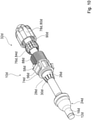
- 2 shows a perspective exploded view of the sealing device 10a.
- the cable insertion section 22a has a stabilizing element 26a (cf. 2 and 3 ).
- the stabilizing element 26a and the soft element 24a are connected to one another in one piece. These are only for the purpose of a clearer presentation Stabilizing element 26a and the soft element 24a shown separately from each other.
- the stabilizing element 26a has a higher strength than the soft element 24a.
- the stabilizing element 26a is arranged entirely within the cable insertion section 22a.
- the stabilization element 26a has a first stabilization section 28a and a second stabilization section 30a.
- the first stabilizing section 28a is in the form of a hollow cylinder.
- the second stabilizing section 30a is formed like a comb.
- the second stabilizing portion 30a has a tapered shape.
- the second stabilizing section 30a is designed in the shape of a truncated cone. Alternatively, the second stabilization section 30a can be configured in the shape of a paraboloid.
- the sealing unit 14a is produced using a multi-component injection molding process.
- the cable insertion section 22a and the sealing section 16a are integrally connected to each other.
- the soft element 24a is part of the cable insertion section 22a and part of the sealing section 16a.
- the soft element 24a and the stabilizing element 26a are connected to one another in one piece.
- the sealing device 10a has a connecting element 32a (cf. 2 and 4 ).
- the connecting element 32a is formed separately from the sealing unit 14a.
- the connecting element 32a can be arranged on the cable insertion section 22a.
- the connecting element 32a establishes a connection between the sealing unit 14a and the sealing panel 34a.
- the connecting element 32a presses the sealing unit 14a against the sealing panel 34a.
- the cable insertion section 22a has an edge element 60a.
- the edge member 60a is arranged at an end of the cable insertion portion 22a.
- the edge element 60a contacts the sealing panel 34a.
- the connecting element 32a presses the edge element 60a against the sealing panel 34a.
- the connecting element 32a provides a seal between of the sealing unit 14a and the sealing panel 34a.
- the connecting element 32a is made of a harder material than the soft element 24a.
- the connecting element 32a is made of a harder material than the edge element 60a.
- the connecting element 32a has a first and a second latching element 56a.
- the latching elements 56a are provided for producing a latching connection between the connecting element 32a and the sealing panel 34a.
- the latching element 56a has a latching lug 58a. In the installed state, the latching element 56a engages in an opening 70a complementary thereto on the sealing panel 34a.
- the connecting element 32a has a strain relief section 36a.
- the strain relief portion 36a is provided to provide strain relief for the object 12a.
- the strain relief section 36a has a clamping element 62a.
- the clamping element 62a fastens the object 12a by means of a clamping connection in the circumferential direction of the object 12a.
- the clamping element 62a can be plastically deformed to produce the clamping connection.
- the clamp connection is detachable.
- figure 5 shows a flow chart of a method for sealing the object 12a in relation to the sealing panel 34a with the sealing device 10a with the sealing unit 14a.
- an insertion step 64a the sealing unit 14a is pushed onto the object 12a.
- the connecting element 32a is pushed onto the sealing unit 14a and arranged on the sealing unit 14a by means of a force fit and/or form fit.
- a latching step 68a the sealing unit 14a is connected to the sealing panel 34a by means of a latching connection by means of the connecting element 32a.
- Figures 6 to 8 show an alternative embodiment of the sealing system 38b.
- the same reference numbers are therefore used for the same assemblies and reference is made to the explanations of Fig. 1 bis 5 referred.
- the letter a is in the reference numerals of the exemplary embodiment in FIGS Figures 1 to 5 by the letter b in the reference numerals of the embodiment of FIG Figures 6 to 8 replaced.
- FIG. 6 shows an alternative sealing system 38b with the sealing device 10b.
- the sealing device 10b has the sealing unit 14b and the connecting element 32b.
- the sealing device 10b is arranged in the receptacle 44b of the sealing panel 34b (cf. 6 and 8).
- 7 shows a perspective exploded view of the sealing device 10b of the alternative sealing system 38b.
- the stabilizing element 26b and the soft element 24b are connected to one another in one piece.
- the stabilizing element 26b and the soft element 24b are shown separately from one another only for the purpose of a clearer representation.
- the connecting element 32b is connected in one piece to the stabilizing element 26b.
- the connecting element 32b of the alternative sealing system 38b is oriented opposite to the connecting element 32b.
- the sealing device 10b is designed in one piece.
- the connecting element 32b is arranged on the sealing panel 34b on an outside of a sleeve bottom 40b.
- the insertion step 64b and the latching step 68b are carried out (cf. figure 5 ).
- the intermediate step 66a is omitted in the method.
- FIG. 9 shows an alternative sealing device 10c in a perspective exploded view with an elongate object 12c.
- the sealing device 10c can be arranged in a receptacle 44c of a sealing panel 34c.
- a stabilizing element 26c and a soft element 24c are integrally connected to one another.
- the stabilizing element 26c and the soft element 24c are shown separately from one another only for the purpose of a clearer representation.
- a strain relief section 36c is designed in several parts.
- the strain relief section 36c is formed in three parts.
- the strain relief section 36c has a connection section 74c for establishing a connection between a connection element 32c and the sealing panel 34c.
- the strain relief section 36c has a strain relief element 76c for direct contacting of an elongate object 12c.
- the strain relief element 76c is designed as a lamellar insert 84c in the form of a tensioning tensioner.
- the strain relief section 36c has a pressurizing element 78c.
- the pressure application element 78c is designed as a cap nut 80c.
- the strain relief element 76c and the pressure application element 78c each have a feed-through area for the feed-through of the elongate object 12c on.
- the strain relief member 76c and the compression member 78c are disposed on the elongate object 12c.
- the connecting section 74c is integrally connected to the stabilizing element 26c.
- the connection portion 74c is arranged on the sealing panel 34c on an outside of a socket bottom 40c.
- the connecting section 74c has a first and a second latching element 56c.
- the latching elements 56c are provided for producing a latching connection between the connecting section 74c and the sealing panel 34c.
- the latching element 56c has a latching lug 58c. In the installed state, the latching element 56c engages in an opening 70c complementary thereto on the sealing panel 34c.
- the connecting section 74c has an external thread 88c.
- the pressure application element 78c has an internal thread 90c complementary to the external thread 88c of the connecting section 74c.
- the strain relief element 76c is arranged between the connecting section 74c and the pressure-exerting element 78c.
- the pressure-exerting element 78c is connected to the connecting section 74c via a non-positive connection between the external thread 88c and an internal thread 90c.
- the pressurizing member 78c applies pressure to the strain relief member 76c.
- the pressure-exerting element 78c presses the strain-relief element 76c into and/or against the connecting section 74c and thereby reduces the feed-through region of the strain-relief element 76c.
- the pressure applied by the pressurizing member 78c is transmitted to the elongate object 12c.
- the mounted state there is a slip resistance between the strain relief element 76c and the elongate object 12c in the circumferential direction.
- a non-positive connection is created between the strain relief element 76c and the elongate object 12c in the circumferential direction.
- FIG. 10 an exploded perspective view of a further sealing device 10d is shown.
- the embodiment of the sealing device 10d differs from the embodiment of the sealing device 10c only in that the sealing device 10d is provided for the passage and sealing of an elongate object 12d with a larger diameter compared to a diameter of the elongate object 12c.
- the insertion step 64c, 64d and the latching step 68c, 68d are carried out (cf. figure 5 ).
- the intermediate step 66a is omitted in the method.
- FIG. 11 shows a further alternative sealing system 38e with a further alternative sealing device 10e.
- the same reference numbers are therefore used for the same assemblies and reference is made to the explanations of Figures 1 to 8 as well as the 9 and 10 referred.
- the letters ad in the reference numerals of the embodiments in the Figures 1 to 10 by the letter e in the reference numerals of the embodiment of FIG figures 11 and 12 replaced.
- the sealing device 10e is arranged in one of receptacles 44e of a sealing panel 34e. On a mounting direction 96e of the sealing device 10e opposite A support unit 94e of a sealing system 38e is arranged on the side of the sealing panel 34e on the receptacle 44e.
- the support unit 94e is provided for receiving and fastening at least one central element of an elongate object 12e and/or of a further elongate object 112e.
- a sealing unit 14e has a sealing section 16e.
- the sealing unit 14e has a further sealing section 116e.
- the further sealing section 116e and the sealing section 16e are of identical design.
- the further sealing section 116e makes contact with a further elongate object 112e that is different from the elongate object 12e.
- the further sealing section 116e seals the further elongate object 112e by means of an intrinsic prestress.
- the further elongate object 112e and the elongate object 12e are of identical design.
- the sealing unit 14e has two cable insertion sections 22e, 122e (cf. 13 ).
- the cable insertion sections 22e, 122e each have a stabilizing element 26e, 126e (cf. 13 ).
- the cable inserting portion 22e is provided for inserting the elongated object 12e.
- the cable inserting portion 122e is provided for inserting the further elongated object 112e.
- the stabilizing elements 26e, 126e are of identical design.
- the stabilization elements 26e, 126e each have a first stabilization section 28e, 128e and a second stabilization section 30e, 130e.
- a connecting element 32e is integrally connected to the stabilizing elements 26e, 126e.
- Soft elements 24e, 124e of the stabilizing elements 26e, 126e are designed in one piece.
- the soft elements 24e, 124e and the stabilizing elements 26e, 126e are connected to one another in one piece.
- the soft elements 24e, 124e and the stabilizing elements 26e, 126e are inseparably connected to one another.
- a strain relief section 36e is designed in several parts.
- the strain relief section 36e is formed in three parts.
- the strain relief section 36e has a connection section 74e for establishing a connection between the connection element 32e and the sealing panel 34e.
- the connecting section 74e has lamellae arranged in the circumferential direction in the form of a lamellar cage 82e.
- the strain relief section 36e has a strain relief element 76e for direct contacting of an elongate object 12e.
- the strain relief element 76e is designed as a flexible element 92 .
- the flexible member 92 may be formed from rubber, neoprene, and/or a thermoplastic material.
- the strain relief element 76e has two feed-through areas for feeding through the elongate object 12e and the further elongate object 112e.
- the strain relief portion 36e includes a pressurizing member 78e.
- the pressure application element 78e is designed as a cap nut 80e.
- the strain relief element 76e and the pressure application element 78e are arranged on the elongate object 12e and on the further elongate object 112e.
- the connecting section 74e is connected in one piece to the stabilizing elements 26e, 126e.
- the connection portion 74e is arranged on the sealing panel 34e on an outside of the socket bottom 40e.
- the connecting section 74e has a first and a second latching element 56e.
- the latching elements 56e are provided for producing a latching connection between the connecting section 74e and the sealing panel 34e.
- the latching element 56e has a latching nose 58e. In the installed state, the latching element 56e engages in an opening 70e complementary thereto on the sealing panel 34e.
- the connecting section 74e has an external thread 88e.
- the pressurizing member 78e has a male thread 88e of the connecting portion 74e complementary internal thread 90e.
- the strain relief element 76e is arranged between the connecting section 74e and the pressure application element 78e.
- the pressure-exerting element 78e is connected to the connecting section 74e via a non-positive connection between the external thread 88e and the internal thread 90e.
- the strain relief element 76e is at least partially arranged inside the lamellar cage 82e.
- the pressurizing element 78e exerts pressure on the laminations of the lamina cage 82 .
- the slats exert pressure on the strain relief element 76e.
- the pressurizing member 78e presses the strain relief member 76e into the connecting portion 74e.
- the pressure application element 78e narrows the lead-through areas of the strain relief element 76e.
- the pressure applied by the pressure-exerting element 78e to the lamellar cage 82e and thus to the strain relief element 76e is transmitted to the elongate object 12e and to the further elongate object 112e.
- a non-positive connection is created between the strain relief element 76e and the elongated object 112e and the further elongated object 112e in the circumferential direction.
- figure 5 shows a flow chart of a method for sealing the object 12a in relation to the sealing panel 34a with the sealing device 10a with the sealing unit 14a.
- an insertion step 64a the sealing unit 14a is pushed onto the object 12a.
- the connecting element 32a is pushed onto the sealing unit 14a and arranged on the sealing unit 14a by means of a force fit and/or form fit.
- a latching step 68a the sealing unit 14a is connected to the sealing panel 34a by means of a latching connection by means of the connecting element 32a.
- the insertion step 64e and the latching step 68e are carried out (cf. figure 5 ).
- An intermediate step 66a is omitted in the method.
Landscapes
- Engineering & Computer Science (AREA)
- Architecture (AREA)
- Civil Engineering (AREA)
- Structural Engineering (AREA)
- Gasket Seals (AREA)
- Installation Of Indoor Wiring (AREA)
Abstract
Die Erfindung geht aus von einer Dichtvorrichtung (10a, 10b, 10c, 10d, 10e) zur Durchführung und Abdichtung eines länglichen Objekts (12a, 12b, 12c, 12d, 12e), mit zumindest einer Dichteinheit (14a, 14b, 14c, 14d, 14e), welche dazu vorgesehen ist, das Objekt (12a, 12b, 12c, 12d, 12e) in einem montierten Zustand zumindest abschnittsweise vollständig in Umfangsrichtung zu umschließen, und welche zumindest einen Dichtabschnitt (16a, 16b, 16c, 16d, 16e) aufweist, welcher dazu vorgesehen ist, in dem montierten Zustand das Objekt (12a, 12b, 12c, 12d, 12e) zu kontaktieren und mittels einer intrinsischen Vorspannung abzudichten.Es wird vorgeschlagen, dass der Dichtabschnitt (16a, 16b, 16c, 16d, 16e) in zumindest einem demontierten Zustand über zumindest einen Großteil seiner Länge einen wenigstens im Wesentlichen konstanten Innendurchmesser (18a, 18b, 18c, 18d, 18e) aufweist.The invention is based on a sealing device (10a, 10b, 10c, 10d, 10e) for leading through and sealing an elongated object (12a, 12b, 12c, 12d, 12e), with at least one sealing unit (14a, 14b, 14c, 14d, 14e), which is intended to completely enclose the object (12a, 12b, 12c, 12d, 12e) in a mounted state, at least in sections, completely in the circumferential direction, and which has at least one sealing section (16a, 16b, 16c, 16d, 16e). , which is intended to contact the object (12a, 12b, 12c, 12d, 12e) in the assembled state and to seal it by means of an intrinsic prestress. It is proposed that the sealing section (16a, 16b, 16c, 16d, 16e) in at least one dismantled state, has an at least essentially constant inner diameter (18a, 18b, 18c, 18d, 18e) over at least a large part of its length.
Description
Die Erfindung betrifft eine Dichtvorrichtung nach dem Oberbegriff des Anspruchs 1 und ein Verfahren zur Abdichtung zumindest eines länglichen Objekts gegenüber einem Dichtpanel nach dem Oberbegriff des Anspruchs 15.The invention relates to a sealing device according to the preamble of claim 1 and a method for sealing at least one elongate object relative to a sealing panel according to the preamble of claim 15.
Aus der
Ferner ist aus der
Des Weiteren offenbart die Druckschrift
Zudem ist aus dem Gebrauchsmuster
Die Aufgabe der Erfindung besteht insbesondere darin, eine gattungsgemäße Dichtvorrichtung mit verbesserten Eigenschaften hinsichtlich einer Montage bereitzustellen. Die Aufgabe wird erfindungsgemäß durch die Merkmale der Ansprüche 1 und 15 gelöst, während vorteilhafte Ausgestaltungen und Weiterbildungen der Erfindung den Unteransprüchen entnommen werden können.The object of the invention consists in particular in providing a generic sealing device with improved properties with regard to assembly. The object is achieved according to the invention by the features of claims 1 and 15, while advantageous configurations and developments of the invention can be found in the dependent claims.
Die Erfindung geht aus von einer Dichtvorrichtung zur Durchführung und Abdichtung eines länglichen Objekts, mit zumindest einer Dichteinheit, welche dazu vorgesehen ist, das Objekt in einem montierten Zustand zumindest abschnittsweise vollständig in Umfangsrichtung zu umschließen, und welche zumindest einen Dichtabschnitt aufweist, welcher dazu vorgesehen ist, in dem montierten Zustand das Objekt zu kontaktieren und mittels einer intrinsischen Vorspannung abzudichten.The invention is based on a sealing device for passing through and sealing an elongate object, with at least one sealing unit which is intended to completely enclose the object in the circumferential direction at least in sections in an assembled state, and which has at least one sealing section which is intended for this purpose , to contact the object in the mounted state and to seal it by means of an intrinsic prestress.
Es wird vorgeschlagen, dass der Dichtabschnitt in zumindest einem demontierten Zustand über zumindest einen Großteil seiner Länge einen wenigstens im Wesentlichen konstanten Innendurchmesser (18a, 18b, 18c, 18d, 18e) aufweist.It is proposed that the sealing section has an at least essentially constant inner diameter (18a, 18b, 18c, 18d, 18e) over at least a large part of its length in at least one dismantled state.
Hierdurch kann vorteilhaft eine Montage vereinfacht werden. Vorteilhaft kann ein zeitsparender Montagevorgang ermöglicht werden. Insbesondere kann eine preisgünstige Ausgestaltung erreicht werden. Insbesondere kann aufgrund einer vorteilhaften Konstruktion eine Vereinfachung einer Montage erzielt werden. Zudem kann eine über eine gesamte Länge eines Dichtabschnitts optimierte Anpassung an ein eingeführtes längliches Objekt erfolgen.As a result, assembly can advantageously be simplified. A time-saving assembly process can advantageously be made possible. In particular, a low-cost configuration can be achieved. In particular, a simplification of assembly can be achieved due to an advantageous construction. In addition, an optimized adjustment over the entire length of a sealing section to an inserted elongate object.
Unter einer "Dichtvorrichtung" soll insbesondere ein Teil eines Dichtsystems, insbesondere einer Kabelmuffe, verstanden werden, welches insbesondere dazu vorgesehen ist, Kabelkontaktierungsstellen gegenüber Umwelteinflüssen zu schützen. Vorzugsweise umfasst das Dichtsystem die Dichtvorrichtung und zumindest eine Einhausung, besonders vorteilhaft eine Muffenhaube, mit einem Dichtpanel, insbesondere einem Muffenboden, an welchem die Dichtvorrichtung anordenbar ist. Insbesondere kann die Dichtvorrichtung zur Durchführung und Abdichtung von mehr als nur einem einzigen länglichen Objekt, insbesondere von zumindest zwei länglichen Objekten, vorgesehen sein.A "sealing device" should be understood in particular as a part of a sealing system, in particular a cable sleeve, which is intended in particular to protect cable contacting points from environmental influences. The sealing system preferably comprises the sealing device and at least one housing, particularly advantageously a sleeve hood, with a sealing panel, in particular a sleeve base, on which the sealing device can be arranged. In particular, the sealing device can be provided for the passage and sealing of more than just a single elongate object, in particular at least two elongate objects.
Unter einem "länglichen Objekt" soll insbesondere ein Objekt verstanden werden, welches in zumindest einem abgewickelten Zustand eine Ausdehnung entlang einer Haupterstreckungsrichtung aufweist, welche zumindest ein zweifaches, vorteilhaft zumindest ein dreifaches, vorzugsweise zumindest ein fünffaches des Durchmessers des Objekts aufweist, welcher insbesondere quer zur Haupterstreckungsrichtung gemessen ist. Insbesondere kann das längliche Objekt eine Ausgestaltung als Rohr, insbesondere als Einblasrohr und/oder vorzugsweise als Kabel, insbesondere als elektrisches Kabel und/oder besonders vorteilhaft als Glasfaserkabel, aufweisen. Unter einer "Haupterstreckungsrichtung" eines Objekts soll dabei insbesondere eine Richtung verstanden werden, welche parallel zu einer längsten Kante eines kleinsten gedachten Quaders verläuft, welcher das Objekt gerade noch vollständig umschließt.An "elongated object" is to be understood in particular as an object which, in at least one unwound state, has an extension along a main extension direction which has at least twice, advantageously at least three times, preferably at least five times the diameter of the object, which in particular is transverse to the Main extension direction is measured. In particular, the elongate object can be designed as a tube, in particular as a blowing tube and/or preferably as a cable, in particular as an electrical cable and/or particularly advantageously as a glass fiber cable. A "main extension direction" of an object is to be understood in particular as a direction which runs parallel to a longest edge of the smallest imaginary cuboid which just about completely encloses the object.
Unter einer "Dichteinheit" soll insbesondere ein Einheit verstanden werden, welche ein Durchdringen von Materie aus einem ersten Bereich in einen zweiten Bereich und umgekehrt und/oder einen Austausch zwischen Materie aus dem ersten und dem zweiten Bereich, zwischen welchen die Dichteinheit zumindest teilweise angeordnet ist, zumindest im Wesentlichen vollständig verhindert. Insbesondere weist die Dichteinheit eine schützende Wirkung gegen Eindringen von Feuchtigkeit und/oder Flüssigkeit auf. Unter "zumindest im Wesentlichen vollständig" soll hier insbesondere verstanden werden, dass ein Durchdringen von Materie aus dem ersten in den zweiten Raum und umgekehrt unterhalb einer für den gedachten Einsatzzweck geeignete und insbesondere gesetzlich und/oder durch Richtlinien festgelegte Leckrate liegt.A "sealing unit" is to be understood in particular as a unit which allows matter to penetrate from a first area into a second area and vice versa and/or an exchange between matter from the first and the second area, between which the sealing unit is at least partially arranged , at least essentially completely prevented. In particular, the sealing unit has a protective effect against the ingress of moisture and/or liquid. Under "at least substantially fully" is meant here In particular, it should be understood that penetration of matter from the first into the second space and vice versa is below a leak rate that is suitable for the intended purpose and is in particular specified by law and/or by guidelines.
Insbesondere weist die Dichteinheit zumindest einen, vorzugsweise genau einen Durchführungskanal für das Objekt auf. Die Dichteinheit kann vorteilhaft zwei, drei oder insbesondere mehrere Durchführungskanäle jeweils für ein Objekt aufweisen. Der Durchführungskanal ist insbesondere dazu vorgesehen, das Objekt aufzunehmen. Insbesondere weist der Durchführungskanal über seine Länge betrachtet einen variablen Durchführungskanaldurchmesser auf. Insbesondere weist der Durchführungskanal eine Länge auf, welche zumindest so groß ist, insbesondere zumindest doppelt so groß ist, vorteilhaft zumindest dreimal so groß ist, wie der maximale Durchführungskanaldurchmesser. Insbesondere weist der Durchführungskanal eine Länge von zumindest 20 mm, vorteilhaft zumindest 30 mm und vorzugsweise zumindest 35 mm auf. Insbesondere beträgt der maximale Durchführungskanaldurchmesser zumindest 5 mm, vorteilhaft zumindest 8 mm und besonders vorteilhaft zumindest 10 mm. Insbesondere weist ein Durchmesser der Dichteinheit über eine Länge der Dichteinheit betrachtet eine variable Größe auf. Insbesondere ist ein maximaler Durchmesser der Dichteinheit zumindest gleich dem maximalen Durchführungskanaldurchmesser, vorzugsweise zumindest gleich einem 1,5 fachen des maximalen Durchführungskanaldurchmessers und/oder bevorzugt zumindest gleich einem 1,9 fachen des maximalen Durchführungskanaldurchmessers. Insbesondere weist der maximale Durchmesser der Dichteinheit einen Wert zwischen 18 mm und 22 mm auf.In particular, the sealing unit has at least one, preferably precisely one, feed-through channel for the object. The sealing unit can advantageously have two, three or, in particular, a plurality of lead-through channels, each for one object. The lead-through channel is intended in particular to accommodate the object. In particular, the feedthrough channel has a variable feedthrough channel diameter over its length. In particular, the feedthrough channel has a length which is at least as great, in particular at least twice as great, advantageously at least three times as great as the maximum feedthrough passage diameter. In particular, the lead-through channel has a length of at least 20 mm, advantageously at least 30 mm and preferably at least 35 mm. In particular, the maximum feedthrough channel diameter is at least 5 mm, advantageously at least 8 mm and particularly advantageously at least 10 mm. In particular, a diameter of the sealing unit has a variable size when viewed over a length of the sealing unit. In particular, a maximum diameter of the sealing unit is at least equal to the maximum through-channel diameter, preferably at least equal to 1.5 times the maximum through-channel diameter and/or preferably at least equal to 1.9 times the maximum through-channel diameter. In particular, the maximum diameter of the sealing unit has a value between 18 mm and 22 mm.
Unter einem "Dichtabschnitt" soll insbesondere ein Teil der Dichteinheit verstanden werden, welcher in einem montierten Zustand dazu vorgesehen ist, eine dichtende Wirkung auszuüben. Der Dichtabschnitt ist insbesondere hohlzylinderförmig mit einem Außen- und einem Innendurchmesser und mit einer Außen- und einer Innenfläche ausgebildet. Insbesondere verläuft der Durchführungskanal für das Objekt zumindest teilweise durch den Dichtabschnitt. Insbesondere dichtet der Dichtabschnitt das Objekt innerhalb des Durchführungskanals zumindest in einer Längsrichtung ab. Unter einem "montierten Zustand" soll insbesondere ein Zustand einer Einheit verstanden werden, in welchem einzelne Bestandteile der Einheit derart zusammengesetzt und/oder miteinander verbunden sind, sodass die Einheit zumindest eine ihr zugewiesene Funktion erfüllen und/oder ausführen kann und gleichzeitig eine der Einheit zugedachte Wirkung auf eine weitere Einheit ausüben kann, wobei insbesondere die Einheit die weitere Einheit kontaktiert. Insbesondere entfaltet die Dichteinheit in dem montierten Zustand eine abdichtende Wirkung auf das Objekt, wobei das Objekt in die Dichteinheit eingeführt ist.A "sealing section" is to be understood in particular as a part of the sealing unit which, in an assembled state, is intended to exert a sealing effect. The sealing section is in particular in the form of a hollow cylinder with an outer and an inner diameter and with an outer and an inner surface. In particular, the lead-through channel for the object runs at least partially through the sealing section. In particular, he writes Sealing section from the object within the feed-through channel at least in a longitudinal direction. An "assembled state" is to be understood in particular as a state of a unit in which individual components of the unit are assembled and/or connected to one another in such a way that the unit can fulfill and/or perform at least one function assigned to it and at the same time one intended for the unit Can exert an effect on another unit, in particular the unit contacts the other unit. In particular, the sealing unit develops a sealing effect on the object in the mounted state, with the object being inserted into the sealing unit.
Vorteilhaft besteht der Dichtabschnitt zumindest teilweise und vorzugsweise vollständig aus einem kolloidartigen Material. Unter einem "kolloidartigen Material" soll Insbesondere ein Material verstanden werden, welches zumindest eine feste und zumindest eine flüssige und/oder gasförmige Komponente aufweist. Insbesondere ist die feste Komponente als eine schwammartige dreidimensionale Matrix ausgebildet, in welcher die flüssige und/oder gasförmige Komponente verteilt ist. Vorzugsweise ist das kolloidartige Material zumindest teilweise und vorzugsweise vollständig als ein Gel, vorzugsweise als ein Polyurethan-Gel, ausgebildet. Insbesondere ist das kolloidartige Material unter Standardbedingungen formbeständig, wobei das Material zumindest unter einer geringen, insbesondere mechanischen Belastung eine reversible Formänderung vollführt und anschließend bei einer Abwesenheit der Belastung seine ursprüngliche Form annimmt. Insbesondere weist das Material elastische Eigenschaften auf. Vorteilhaft ist das kolloidartige Material insbesondere reversibel verformbar, wobei es eine vor einer Verformung bestehende Form einnimmt. Insbesondere kann das kolloidartige Material seine Ausdehnung insbesondere in mehrere Dimensionen ändern, wobei beispielsweise mit einer Längenänderung der Form des kolloidartigen Materials eine Breitenänderung der Form des kolloidartigen Materials einhergeht.Advantageously, the sealing section consists at least partially and preferably entirely of a colloidal material. A “colloid-like material” is to be understood in particular as meaning a material which has at least one solid and at least one liquid and/or gaseous component. In particular, the solid component is designed as a spongy three-dimensional matrix in which the liquid and/or gaseous component is distributed. The colloid-like material is preferably at least partially and preferably completely formed as a gel, preferably as a polyurethane gel. In particular, the colloidal material is dimensionally stable under standard conditions, the material undergoing a reversible change in shape at least under a small, in particular mechanical, load and then, in the absence of the load, assuming its original shape. In particular, the material has elastic properties. Advantageously, the colloidal material is in particular reversibly deformable, taking on a shape that existed prior to deformation. In particular, the colloidal material can change its extent, in particular in several dimensions, with a change in length of the shape of the colloidal material being accompanied by a change in width of the shape of the colloidal material.
Unter einer "intrinsischen Vorspannung" soll insbesondere eine Eigenschaft einer Einheit verstanden werden, bei welcher die Einheit bei einem Kontaktieren einer weiteren, abzudichtenden Einheit eine selbstdichtende Funktion entfaltet, ohne Zuhilfenahme von anderen Einheiten.An "intrinsic pretension" is to be understood in particular as a property of a unit in which the unit unfolds a self-sealing function when it comes into contact with a further unit to be sealed, without assistance of other units.
Unter "vorgesehen" soll insbesondere speziell programmiert, ausgelegt und/oder ausgestattet verstanden werden. Darunter, dass ein Objekt zu einer bestimmten Funktion vorgesehen ist, soll insbesondere verstanden werden, dass das Objekt diese bestimmte Funktion in zumindest einem Anwendungs- und/oder Betriebszustand erfüllt und/oder ausführt.“Provided” should be understood to mean, in particular, specially programmed, designed and/or equipped. The fact that an object is provided for a specific function is to be understood in particular to mean that the object fulfills and/or executes this specific function in at least one application and/or operating state.
Ferner wird vorgeschlagen, dass die Dichteinheit zumindest einen weiteren Dichtabschnitt aufweist, welcher dazu vorgesehen ist, in dem montierten Zustand ein von dem länglichen Objekt verschiedenes weiteres längliches Objekt zu kontaktieren und mittels einer intrinsischen Vorspannung abzudichten. Dadurch kann insbesondere eine Abdichtung von mehreren länglichen Objekten vorteilhaft unabhängig voneinander erfolgen. Es ist denkbar, dass die Dichteinheit eine Vielzahl von weiteren Dichtabschnitten aufweist, welche jeweils ein längliches Objekt durchführen und abdichten. Insbesondere sind der Dichtabschnitt und der weitere Dichtabschnitt/die weiteren Dichtabschnitte nebeneinander angeordnet. Vorteilhaft sind der Dichtabschnitt und der weitere Dichtabschnitt/die weiteren Dichtabschnitte identisch ausgebildet und weisen vorteilhaft identische Eigenschaften auf. Alternativ können der Dichtabschnitt und der weitere Dichtabschnitt/die weiteren Dichtabschnitte verschieden ausgebildet sein. Insbesondere besteht der weitere Dichtabschnitt zumindest teilweise und vorzugsweise vollständig aus einem kolloidartigen Material.Furthermore, it is proposed that the sealing unit has at least one further sealing section, which is provided in the installed state to contact a further elongate object that is different from the elongate object and to seal it by means of an intrinsic prestress. In this way, in particular, a plurality of elongate objects can advantageously be sealed independently of one another. It is conceivable that the sealing unit has a multiplicity of further sealing sections, each of which passes through and seals an elongate object. In particular, the sealing section and the further sealing section/s are arranged next to one another. The sealing section and the further sealing section/the further sealing sections are advantageously of identical design and advantageously have identical properties. Alternatively, the sealing section and the additional sealing section/the additional sealing sections can be designed differently. In particular, the further sealing section consists at least partially and preferably completely of a colloidal material.
. Insbesondere liegt der Dichtabschnitt und/oder der weitere Dichtabschnitt über seine gesamte Länge in einem am länglichen Objekt montierten Zustand der Dichteinheit dicht an dem länglichen Objekt an. Insbesondere übt der Dichtabschnitt und/oder der weitere Dichtabschnitt in dem montierten Zustand ein radial nach innen gerichteten Druck auf das längliche Objekt in einem montierten Zustand aus. Vorteilhaft liegt der Druck in dem montierten Zustand über die gesamte Länge des Dichtabschnitts und/oder der weiteren Dichtabschnitte dauerhaft an.. In particular, the sealing section and/or the further sealing section lies tightly against the elongate object over its entire length when the sealing unit is mounted on the elongate object. In particular, the sealing section and/or the further sealing section exerts a radially inwardly directed pressure on the elongate object in a mounted state. In the installed state, the pressure is advantageously permanently applied over the entire length of the sealing section and/or the further sealing sections.
Unter einem "demontierten Zustand" soll insbesondere ein Zustand einer Einheit verstanden werden, in welchem die Einheit wirkungs- und/oder funktionslos insbesondere gegenüber einer weiteren Einheit ist und/oder die Einheit und die weitere Einheit kontaktlos sind.A “disassembled state” is intended to mean, in particular, a state of a unit be understood, in which the unit is ineffective and / or functionless in particular compared to another unit and / or the unit and the other unit are contactless.
Zudem wird vorgeschlagen, dass der Dichtabschnitt und/oder der weitere Dichtabschnitt in zumindest einem demontierten Zustand jeweils über zumindest einen Großteil seiner Länge einen wenigstens im Wesentlichen konstanten Außendurchmesser aufweist. Dadurch kann insbesondere eine gleichmäßige Dichtwirkung auf das längliche Objekt in dem montierten Zustand erreicht werden, vorzugsweise an jedem Kontaktpunkt zwischen dem Dichtabschnitt und/oder dem weiteren Dichtabschnitt und dem länglichen Objekt in dem montierten Zustand. Insbesondere ist der Außendurchmesser des Dichtabschnitts und/oder des weiteren Dichtabschnitts größer als die Länge des Dichtabschnitts und/oder des weiteren Dichtabschnitts.In addition, it is proposed that the sealing section and/or the further sealing section have an at least essentially constant outer diameter in at least one dismantled state over at least a large part of its length. In this way, in particular, a uniform sealing effect on the elongate object can be achieved in the assembled state, preferably at each contact point between the sealing section and/or the further sealing section and the elongate object in the assembled state. In particular, the outer diameter of the sealing section and/or the further sealing section is greater than the length of the sealing section and/or the further sealing section.
Ferner wird vorgeschlagen, dass die Dichteinheit zumindest einen Kabeleinführabschnitt zur Einführung des Objekts aufweist. Alternativ kann die Dichteinheit vorteilhaft zwei, insbesondere mehrere Kabeleinführabschnitte jeweils zur Einführung eines Objekts aufweisen. Hierdurch kann insbesondere eine Einführhilfe für einen Techniker bei einer Montage bereitgestellt werden, wodurch eine Zeitersparnis erzielt werden kann. Insbesondere kann dadurch eine Prozesssicherheit bei der Montage vorteilhaft erhöht werden. Insbesondere sind der Kabeleinführabschnitt/die Kabeleinführabschnitte und der Dichtabschnitt und/oder der weitere Dichtabschnitt einstückig miteinander verbunden. Unter "einstückig" soll insbesondere zumindest stoffschlüssig verbunden verstanden werden, beispielsweise durch einen Schweißprozess, einen Klebeprozess, einen Anspritzprozess und/oder einen anderen, dem Fachmann als sinnvoll erscheinenden Prozess, und/oder vorteilhaft in einem Stück geformt verstanden werden, wie beispielsweise durch eine Herstellung aus einem Guss und/oder durch eine Herstellung in einem Ein- oder Mehrkomponentenspritzverfahren und/oder durch Herstellung in einem Druckverfahren und vorteilhaft aus einem einzelnen Rohling. Der Kabeleinführabschnitt/die Kabeleinführabschnitte ist/sind insbesondere als Hohlkörper ausgebildet. Insbesondere weist/weisen der Kabeleinführabschnitt/die Kabeleinführabschnitte entlang seiner/ihrer jeweiligen Haupterstreckungsrichtung einen unterschiedlichen Außen- und/oder Innendurchmesser auf. Insbesondere weist/weisen der Kabeleinführabschnitt/die Kabeleinführabschnitte im Mittel jeweils einen größeren Außen- und/oder Innendurchmesser als ein Außen- und/oder Innendurchmessen des Dichtabschnitts und/oder der weiteren Dichtabschnitte auf. Insbesondere weist/weisen der Kabeleinführabschnitt/die Kabeleinführabschnitte jeweils einen größeren Innendurchmesser im Vergleich zu einem Durchmesser des länglichen Objekts/der länglichen Objekte auf. Der Kabeleinführabschnitt/die Kabeleinführabschnitte weist/weisen jeweils insbesondere eine konische Form auf, welche sich in Richtung des Dichtabschnitts und/oder der weiteren Dichtabschnitte verjüngt. Vorzugsweise zentriert/zentrieren der Kabeleinführabschnitt/die Kabeleinführabschnitte das jeweilige längliche Objekt bei einem Einführvorgang.It is also proposed that the sealing unit has at least one cable insertion section for inserting the object. Alternatively, the sealing unit can advantageously have two, in particular multiple, cable insertion sections, each for inserting an object. In this way, in particular, an insertion aid can be provided for a technician during assembly, as a result of which a time saving can be achieved. In particular, this can advantageously increase process reliability during assembly. In particular, the cable insertion section/the cable insertion sections and the sealing section and/or the further sealing section are connected to one another in one piece. "In one piece" is to be understood in particular as being at least cohesively connected, for example by a welding process, an adhesive process, a spraying process and/or another process that appears sensible to the person skilled in the art, and/or advantageously formed in one piece, such as by a Manufacture from a single cast and/or by manufacture in a one-component or multi-component injection molding process and/or by manufacture in a pressure process and advantageously from a single blank. The cable insertion section/cable insertion sections is/are in particular as a hollow body educated. In particular, the cable insertion section(s) has/have a different outer and/or inner diameter along its/their respective main extension direction. In particular, the cable insertion section(s) has/have a larger average outer and/or inner diameter than an outer and/or inner diameter of the sealing section and/or the further sealing sections. In particular, the cable insertion section/sections each have a larger inner diameter compared to a diameter of the elongate object/objects. The cable insertion section/the cable insertion sections has/have in particular a conical shape which tapers in the direction of the sealing section and/or the further sealing sections. Preferably, the cable insertion portion(s) center(s) the respective elongate object during an insertion operation.
Des Weiteren wird vorgeschlagen, dass der Dichtabschnitt und/oder der weitere Dichtabschnitt und/oder der Kabeleinführabschnitt/die Kabeleinführabschnitte jeweils eine rotationssymmetrische Außen- und/oder Innenfläche aufweist/aufweisen. Hierdurch kann insbesondere eine kostengünstige Herstellung ermöglicht werden. Der Dichtabschnitt und/oder der weitere Dichtabschnitt und/oder der Kabeleinführabschnitt/die Kabeleinführabschnitte weisen jeweils insbesondere eine Rotationssymmetrieachse für beliebige Rotationswinkel auf. Der Dichtabschnitt und/oder der weitere Dichtabschnitt und/oder der Kabeleinführabschnitt/die Kabeleinführabschnitte sind insbesondere jeweils als Hohlkörper ausgebildet. Die Innenfläche des Dichtabschnitts und/oder der weiteren Dichtabschnitte und des Kabeleinführabschnitts/der Kabeleinführabschnitte begrenzen jeweils insbesondere einen Hohlraum der Dichteinheit, welcher insbesondere dazu vorgesehen ist, das längliche Objekt aufzunehmen. Der Hohlraum ist insbesondere entlang der Rotationssymmetrieachse ausgedehnt. Insbesondere weist/weisen der Kabeleinführabschnitt/die Kabeleinführabschnitte jeweils einen ersten Abschnitt, welcher zylinderförmig ausgebildet ist, und einen zweiten Abschnitt, welcher eine rotationssymmetrische, eng zulaufende Gestalt, beispielsweise eine kegelstumpfförmige oder eine paraboloidförmige Gestalt, aufweist. Die Gestalt des Kabeleinführabschnitts/der Kabeleinführabschnitte ist insbesondere dazu vorgesehen, die Dichteinheit und/oder das längliche Objekt innerhalb der Dichteinheit insbesondere bei einem Einführvorgang auszurichten und vorzugsweise zu zentrieren. Dadurch kann insbesondere ein Montagevorgang erleichtert werden. Vorzugsweise ist/sind der Kabeleinführabschnitt/die Kabeleinführabschnitte und der Dichtabschnitt und/oder der weitere Dichtabschnitt einstückig miteinander verbunden. Insbesondere sind der Kabeleinführabschnitt/die Kabeleinführabschnitte und der Dichtabschnitt und/oder der weitere Dichtabschnitt zumindest teilweise aus einem gleichen Material ausgebildet.Furthermore, it is proposed that the sealing section and/or the further sealing section and/or the cable insertion section/the cable insertion sections each have/have a rotationally symmetrical outer and/or inner surface. In this way, in particular, cost-effective production can be made possible. The sealing section and/or the further sealing section and/or the cable insertion section/the cable insertion sections each have, in particular, an axis of rotational symmetry for any angle of rotation. The sealing section and/or the further sealing section and/or the cable insertion section/the cable insertion sections are in particular each formed as a hollow body. The inner surface of the sealing section and/or the further sealing sections and the cable insertion section/s each delimit in particular a cavity of the sealing unit, which is provided in particular to accommodate the elongate object. The cavity is extended in particular along the axis of rotational symmetry. In particular, the cable insertion section(s) has/have a first section, which is cylindrical, and a second section, which has a rotationally symmetrical, narrowly tapering shape, for example a truncated cone shape or a paraboloidal shape. The shape of the cable insertion section(s) is/are intended in particular to align and preferably center the sealing unit and/or the elongate object within the sealing unit, in particular during an insertion process. In this way, an assembly process in particular can be facilitated. The cable insertion section/the cable insertion sections and the sealing section and/or the further sealing section is/are preferably connected to one another in one piece. In particular, the cable insertion section/the cable insertion sections and the sealing section and/or the further sealing section are at least partially made of the same material.
Darüber hinaus wird vorgeschlagen, dass der Kabeleinführabschnitt/die Kabeleinführabschnitte jeweils zumindest ein Weichelement und jeweils zumindest ein Stabilisierungselement mit einer höheren Festigkeit als das Weichelement aufweist/aufweisen. Vorteilhaft sind die Stabilisierungselemente identisch ausgebildet. Hierdurch kann insbesondere eine vorteilhafte Handhabung ermöglicht werden. Vorteilhaft besteht das Weichelement auf dem kolloidartigen Material. Insbesondere bildet das Weichelement eine Außenschicht des Kabeleinführabschnitts/der Kabeleinführabschnitte und definiert insbesondere die Außenfläche des Kabeleinführabschnitts/der Kabeleinführabschnitte. Insbesondere weist/weisen das Stabilisierungselement/die Stabilisierungselemente jeweils zumindest im Wesentlichen eine rotationssymmetrische, eng zulaufende Form auf, welche der Gestalt des jeweiligen ersten und des jeweiligen zweiten Abschnitts des Kabeleinführabschnitts/der Kabeleinführabschnitte entspricht. Vorteilhaft bildet/bilden das Stabilisierungselement/die Stabilisierungselemente jeweils eine Innenschicht des Kabeleinführabschnitts/der Kabeleinführabschnitte und definiert/definieren insbesondere die Innenfläche des Kabeleinführabschnitts/der Kabeleinführabschnitte. Das Stabilisierungselement/die Stabilisierungselemente ist/sind jeweils insbesondere vollständig innerhalb des Kabeleinführabschnitts/der Kabeleinführabschnitte angeordnet. Das Stabilisierungselement/die Stabilisierungselemente kann/können jeweils insbesondere aus einem thermoplastischen Kunststoff hergestellt sein. Alternativ kann/können das Stabilisierungselement/die Stabilisierungselemente jeweils aus einem metallischen Material oder einem Kompositwerkstoff hergestellt sein. Das Stabilisierungselement/die Stabilisierungselemente jeweils ist/sind insbesondere zur Stabilisierung des Kabeleinführabschnitts/der Kabeleinführabschnitte gegenüber einer radialen Belastung vorgesehen. Alternativ oder zusätzlich kann/können das Stabilisierungselement/die Stabilisierungselemente jeweils dazu vorgesehen sein, das längliche Objekt zu fixieren und/oder als Druckabstreifer zum Abstreifen, beispielsweise von Schmutzpartikeln bei dem Einführvorgang von dem länglichen Objekt, zu fungieren.In addition, it is proposed that the cable insertion section/cable insertion sections each have/have at least one soft element and each at least one stabilizing element with a higher strength than the soft element. The stabilizing elements are advantageously of identical design. In this way, in particular, advantageous handling can be made possible. The soft element advantageously consists of the colloidal material. In particular, the soft element forms an outer layer of the cable insertion section(s) and in particular defines the outer surface of the cable insertion section(s). In particular, the stabilizing element/the stabilizing elements each have at least essentially a rotationally symmetrical, tapering shape which corresponds to the shape of the respective first and the respective second section of the cable insertion section/s. Advantageously, the stabilizing element(s) form(s) an inner layer of the cable insertion section(s) and define(s) in particular the inner surface of the cable insertion section(s). The stabilizing element/the stabilizing elements is/are each arranged in particular completely within the cable insertion section/the cable insertion sections. The stabilization element / the stabilization elements can / can each in particular made of a thermoplastic be made of plastic. Alternatively, the stabilizing element(s) can each be made of a metallic material or a composite material. The stabilizing element/the stabilizing elements is/are provided in particular for stabilizing the cable insertion section/the cable insertion sections with respect to a radial load. Alternatively or additionally, the stabilization element/the stabilization elements can each be provided to fix the elongate object and/or to function as a pressure wiper for wiping off dirt particles, for example, during the insertion process from the elongate object.
Weiterhin wird vorgeschlagen, dass das Stabilisierungselement/die Stabilisierungselemente jeweils zumindest einen ersten Stabilisierungsabschnitt und zumindest einen kammartig ausgebildeten zweiten Stabilisierungsabschnitt aufweist. Dadurch kann insbesondere eine flexible Stabilisierung erzielt werden. Insbesondere ist das erste Stabilisierungsabschnitt zylinderförmig ausgebildet. Vorteilhaft weist der zweite Stabilisierungsabschnitt eine höhere Flexibilität als der erste Stabilisierungsabschnitt auf, insbesondere aufgrund einer Geometrie. Insbesondere können sich während des Einführvorgangs einzelne Zinken des kammartig ausgebildeten zweiten Abschnitts nach außen biegen und damit einen Durchmesser des zweiten Stabilisierungsabschnitts vergrößern. Insbesondere bildet der jeweilige zweite Stabilisierungsabschnitt des Stabilisierungselements/der Stabilisierungselemente einen Übergang zu dem Dichtabschnitt und/oder den weiteren Dichtabschnitten.Furthermore, it is proposed that the stabilization element/the stabilization elements each have at least one first stabilization section and at least one comb-like second stabilization section. In this way, in particular, flexible stabilization can be achieved. In particular, the first stabilization section is cylindrical. The second stabilization section advantageously has greater flexibility than the first stabilization section, in particular due to its geometry. In particular, during the insertion process, individual prongs of the comb-like second section can bend outwards and thus increase a diameter of the second stabilization section. In particular, the respective second stabilization section of the stabilization element(s) forms a transition to the sealing section and/or the further sealing sections.
Außerdem wird vorgeschlagen, dass die Dichteinheit einstückig ausgebildet ist. Hierdurch kann insbesondere ein erleichterter Montagevorgang ermöglicht werden. Dadurch kann insbesondere eine robuste Konstruktion gegenüber Zug- und/oder Scherbelastungen erreicht werden. Insbesondere sind das Weichelement und das Stabilisierungselement/die Stabilisierungselemente jeweils einstückig miteinander verbunden. Insbesondere sind das Weichelement und das Stabilisierungselement/die Stabilisierungselemente untrennbar miteinander verbunden.In addition, it is proposed that the sealing unit is designed in one piece. In this way, in particular, an easier assembly process can be made possible. In this way, in particular, a robust construction with respect to tensile and/or shearing loads can be achieved. In particular, the soft element and the stabilizing element/the stabilizing elements are each connected to one another in one piece. In particular, the soft element and the stabilizing element/the stabilizing elements are inseparably connected to one another.
Hierdurch kann insbesondere eine Austauschbarkeit der Dichteinheit erleichtert werden.In this way, in particular, an exchangeability of the sealing unit can be facilitated.
Zudem wird vorgeschlagen, dass die Dichteinheit mittels eines Mehrkomponentenspritzverfahrens, vorzugsweise mittels eines Zweikomponentenspritzverfahrens, hergestellt ist. Hierdurch kann insbesondere eine kostengünstige Herstellung ermöglicht werden. Alternativ kann die Dichteinheit mittels eines Druckverfahrens hergestellt sein. Insbesondere kann die Dichteinheit in einem Herstellungsschritt hergestellt sein.In addition, it is proposed that the sealing unit is produced using a multi-component injection molding process, preferably using a two-component injection molding process. In this way, in particular, cost-effective production can be made possible. Alternatively, the sealing unit can be produced by means of a printing process. In particular, the sealing unit can be produced in one production step.
Ferner wird vorgeschlagen, dass die Dichtvorrichtung ein Verbindungselement zur Herstellung einer Verbindung der Dichteinheit mit einem Dichtpanel aufweist, wobei das Verbindungselement insbesondere dazu vorgesehen ist, die Dichteinheit in einem verbundenen Zustand an das Dichtpanel zu pressen. Hierdurch kann insbesondere eine vorteilhafte Abdichtung zwischen der Dichteinheit und dem Dichtpanel hergestellt werden. Insbesondere weist das Verbindungselement zumindest ein Rastelement zur Herstellung einer Rastverbindung zwischen dem Verbindungselement und dem Dichtpanel auf. Vorteilhaft weist das Rastelement eine Rastnase auf. Insbesondere durch die Herstellung der Rastverbindung presst das Verbindungselement ein Randelement des Kabeleinführabschnitts/der Kabeleinführabschnitte gegen das Dichtpanel, wodurch vorteilhaft eine Abdichtung stattfindet. Das Verbindungselement ist insbesondere aus einem härteren Material gebildet als das Weichelement der Dichteinheit.It is also proposed that the sealing device has a connecting element for establishing a connection between the sealing unit and a sealing panel, the connecting element being provided in particular for pressing the sealing unit against the sealing panel in a connected state. In this way, in particular, an advantageous seal can be produced between the sealing unit and the sealing panel. In particular, the connecting element has at least one latching element for producing a latching connection between the connecting element and the sealing panel. The latching element advantageously has a latching lug. In particular, by producing the latching connection, the connecting element presses an edge element of the cable entry section(s) against the sealing panel, which advantageously results in a seal. The connecting element is in particular formed from a harder material than the soft element of the sealing unit.
Ferner wird vorgeschlagen, dass das Verbindungselement separat von der Dichteinheit, insbesondere separat von dem Stabilisierungselement/den Stabilisierungselementen, ausgebildet ist. Hierdurch kann insbesondere eine kostengünstige Ersatzteilbeschaffung ermöglicht werden. Insbesondere kann eine Verriegelung der Dichtvorrichtung innerhalb eines Dichtsystems, insbesondere einer Kabelmuffe, ermöglicht werden, wodurch eine Zuverlässigkeit gesteigert werden kann. Insbesondere ist das Verbindungselement auf die Dichteinheit aufschiebbar und kontaktiert die Dichteinheit zumindest im Wesentlichen im Bereich des Kabeleinführabschnitts/der Kabeleinführabschnitte. In dem montierten Zustand der Dichteinheit ist insbesondere das Randelement entgegen einer Einführrichtung des länglichen Elements durch das Verbindungselement mit einem Druck beaufschlagt. Unter einer "Einführrichtung" soll insbesondere eine Richtung verstanden werden, welche parallel zu dem Durchführungskanal verläuft und von dem Kabeleinführabschnitt/den Kabeleinführabschnitten zu dem Dichtabschnitt und/oder den weiteren Dichtabschnitten zeigt.Furthermore, it is proposed that the connecting element is formed separately from the sealing unit, in particular separately from the stabilizing element(s). In this way, in particular, a cost-effective procurement of spare parts can be made possible. In particular, locking of the sealing device within a sealing system, in particular a cable sleeve, can be made possible, as a result of which reliability can be increased. In particular, the connecting element can be slid onto the sealing unit and contacts the sealing unit at least essentially in the region of the cable insertion section/s cable entry sections. In the assembled state of the sealing unit, in particular the edge element is subjected to pressure by the connecting element counter to an insertion direction of the elongate element. An “insertion direction” is to be understood in particular as a direction which runs parallel to the lead-through channel and points from the cable insertion section(s) to the sealing section and/or the further sealing sections.
Alternativ kann das Verbindungselement mit der Dichteinheit, insbesondere einteilig, verbunden sein. Dadurch kann insbesondere eine Vereinfachung der Montage erreicht werden. Zudem kann insbesondere eine Bauteilanzahl reduziert werden. In dem montierten Zustand der Dichteinheit ist insbesondere das Randelement in der Einführrichtung des länglichen Elements durch das Verbindungselement mit einem Druck beaufschlagt. Insbesondere bildet ein zylindrischer Bereich des Verbindungselements mit dem Kabeleinführabschnitt/den Kabeleinführabschnitten der Dichteinheit einen Einführabschnitt für das längliche Objekt. Vorteilhaft soll unter einstückig auch einteilig verstanden werden. Unter "einteilig" soll insbesondere in einem Stück geformt verstanden werden. Vorzugsweise wird dieses eine Stück aus einem einzelnen Rohling, einer Masse und/oder einem Guss, besonders bevorzugt in einem Spritzgussverfahren, insbesondere einem Ein- und/oder Mehrkomponenten-Spritzgussverfahren, hergestellt.Alternatively, the connecting element can be connected to the sealing unit, in particular in one piece. In this way, in particular, a simplification of the assembly can be achieved. In addition, in particular a number of components can be reduced. In the mounted state of the sealing unit, in particular the edge element is subjected to pressure by the connecting element in the insertion direction of the elongate element. In particular, a cylindrical area of the connecting element forms an insertion section for the elongate object with the cable insertion section(s) of the sealing unit. Advantageously, one-piece should also be understood as one-piece. “In one piece” is to be understood in particular as being formed in one piece. This one piece is preferably produced from a single blank, a mass and/or a cast, particularly preferably in an injection molding process, in particular a single-component and/or multi-component injection molding process.
Des Weiteren wird vorgeschlagen, dass das Verbindungselement zumindest einen Zugentlastungsabschnitt zur Bereitstellung einer Zugentlastung des Objekts aufweist. Hierdurch kann insbesondere eine unvorteilhafte Zug- und/oder Druckbelastung auf das längliche Objekt vermieden werden. Insbesondere kann der Zugentlastungsabschnitt das Objekt mittels eines Form- und/oder Kraftschlusses an der Dichteinheit befestigen. Vorteilhaft weist der Zugentlastungsabschnitt zumindest ein Klemmelement auf, welches dazu vorgesehen ist, das längliche Objekt, insbesondere ein Kabel, mittels zumindest einer Klemmverbindung zu befestigen. Insbesondere kontaktiert das Klemmelement das längliche Objekt vorzugsweise in Umfangsrichtung. Das Klemmelement ist insbesondere plastisch verformbar. Die Klemmverbindung ist insbesondere lösbar.Furthermore, it is proposed that the connecting element has at least one strain relief section for providing strain relief for the object. In this way, in particular, an unfavorable tensile and/or compressive load on the elongate object can be avoided. In particular, the strain relief section can attach the object to the sealing unit by means of a form fit and/or force fit. Advantageously, the strain relief section has at least one clamping element which is provided for fastening the elongate object, in particular a cable, by means of at least one clamping connection. In particular, the clamping element contacts the elongate object preferably in the circumferential direction. The clamping element is in particular plastically deformable. the Clamping connection is in particular detachable.
In einer weiteren Ausgestaltung wird darüber hinaus vorgeschlagen, dass das Verbindungselement mit dem Stabilisierungselement/den Stabilisierungselementen verbunden ist. Hierdurch kann insbesondere eine einfache und/oder zeitsparende Montage ermöglicht werden. Zudem kann insbesondere eine Bauteilanzahl reduziert werden. Vorteilhaft ist das Verbindungselement mit dem Stabilisierungselement/den Stabilisierungselementen jeweils einstückig verbunden. Insbesondere bestehen das Verbindungselement und das Stabilisierungselement/die Stabilisierungselemente aus einem gleichen Material, welches härter ist als das Weichelement.In a further embodiment, it is also proposed that the connecting element is connected to the stabilizing element(s). In this way, in particular, simple and/or time-saving assembly can be made possible. In addition, in particular a number of components can be reduced. Advantageously, the connecting element is connected in one piece to the stabilizing element(s). In particular, the connecting element and the stabilizing element/the stabilizing elements consist of the same material, which is harder than the soft element.
Zudem wird ein Dichtsystem mit einer Dichtvorrichtung und mit zumindest einem Dichtpanel, insbesondere einem Muffenboden, vorgeschlagen, welches zumindest eine Aufnahme aufweist, in welcher die Dichteinheit zumindest teilweise anordenbar ist. Vorteilhaft weist das Dichtpanel mehrere Aufnahmen zur Aufnahme von jeweils einer Dichteinheit auf. Hierdurch kann insbesondere eine vorteilhafte Anordnung und Abdichtung der Dichteinheit und des länglichen Objekts, vorteilhaft von mehreren Dichteinheiten und von mehreren länglichen Objekten, erreicht werden. Die Aufnahmen können insbesondere unterschiedliche Formen und/oder Durchmesser und/oder Größen aufweisen. Insbesondere weist das Dichtpanel zu jeder Aufnahme ein Verschlusselement auf, wobei die Aufnahme durch das Verschlusselement verschlossen ist und insbesondere abgedichtet ist. Das Verschlusselement ist insbesondere mit dem Dichtpanel entfernbar verbunden, wodurch die Dichtvorrichtung in der jeweiligen Aufnahme anordenbar ist. Im Falle einer Montage der Dichtvorrichtung ist insbesondere das Verschlusselement durch einen Monteur irreversibel entfernbar. Die Aufnahme ist insbesondere durch die darin angeordnete Dichtvorrichtung abgedichtet. Weitere Aufnahmen bleiben vorteilhaft verschlossen, wenn darin keine Dichtvorrichtungen angeordnet sind.In addition, a sealing system with a sealing device and with at least one sealing panel, in particular a sleeve base, is proposed, which has at least one receptacle in which the sealing unit can be arranged at least partially. The sealing panel advantageously has a plurality of receptacles for receiving one sealing unit each. In this way, in particular, an advantageous arrangement and sealing of the sealing unit and the elongate object, advantageously of a plurality of sealing units and of a plurality of elongate objects, can be achieved. In particular, the receptacles can have different shapes and/or diameters and/or sizes. In particular, the sealing panel has a closure element for each receptacle, the receptacle being closed and in particular sealed by the closure element. In particular, the closure element is removably connected to the sealing panel, as a result of which the sealing device can be arranged in the respective receptacle. In the case of assembly of the sealing device, in particular the closure element can be irreversibly removed by a fitter. The receptacle is sealed in particular by the sealing device arranged therein. Further receptacles advantageously remain closed if no sealing devices are arranged in them.
Ferner geht die Erfindung aus von einem Verfahren zur Abdichtung zumindest eines länglichen Objekts gegenüber einem Dichtpanel mit einer Dichtvorrichtung mit zumindest einer Dichteinheit, durch welche das Objekt, insbesondere zwei Objekte, in einem montierten Zustand zumindest abschnittsweise vollständig in Umfangsrichtung umschlossen wird und welche zumindest einen Dichtabschnitt und insbesondere einen weiteren Dichtabschnitt aufweist, durch welchen/welche das Objekt/die Objekte in dem montierten Zustand kontaktiert/kontaktieren und mittels einer intrinsischen Vorspannung insbesondere des Dichtabschnitts und/oder der weiteren Dichtabschnitte abgedichtet wird.Furthermore, the invention is based on a method for sealing at least one elongate object in relation to a sealing panel with a sealing device with at least one sealing unit, by which the object, in particular two objects, is completely enclosed at least in sections in the circumferential direction in an assembled state and which has at least one sealing section and in particular a further sealing section, through which the object/objects is/are in the assembled state is contacted/contacted and sealed by means of an intrinsic pretension, in particular of the sealing section and/or the further sealing sections.
Es wird vorgeschlagen, dass die Dichteinheit auf das Objekt, insbesondere auf die Objekte, geschoben und anschließend insbesondere mittels eines Verbindungselements mit einem Dichtpanel verbunden wird. Hierdurch kann insbesondere eine Montage verbessert und/oder vereinfacht werden.It is proposed that the sealing unit is pushed onto the object, in particular onto the objects, and then connected to a sealing panel, in particular by means of a connecting element. In this way, in particular, assembly can be improved and/or simplified.
Die erfindungsgemäße Dichtvorrichtung soll hierbei nicht auf die oben beschriebene Anwendung und Ausführungsform beschränkt sein. Insbesondere kann die erfindungsgemäße Dichtvorrichtung zu einer Erfüllung einer hierin beschriebenen Funktionsweise eine von einer hierin genannten Anzahl von einzelnen Elementen, Bauteilen und Einheiten abweichende Anzahl aufweisen.The sealing device according to the invention should not be limited to the application and embodiment described above. In particular, the sealing device according to the invention can have a number of individual elements, components and units that differs from the number specified here in order to fulfill a function described herein.
Weitere Vorteile ergeben sich aus der folgenden Zeichnungsbeschreibung. In den Zeichnungen sind fünf Ausführungsbeispiele der Erfindung dargestellt. Die Zeichnungen, die Beschreibung und die Ansprüche enthalten zahlreiche Merkmale in Kombination. Der Fachmann wird die Merkmale zweckmäßigerweise auch einzeln betrachten und zu sinnvollen weiteren Kombinationen zusammenfassen.Further advantages result from the following description of the drawing. Five exemplary embodiments of the invention are shown in the drawings. The drawings, the description and the claims contain numerous features in combination. The person skilled in the art will expediently also consider the features individually and combine them into further meaningful combinations.
Es zeigen:
- Fig. 1
- Einen Teil eines Dichtsystems mit einem als Muffenboden ausgebildeten Dichtpanel und mit einer Dichtvorrichtung in einem montierten Zustand,
- Fig. 2
- eine perspektivische Explosionsdarstellung der Dichtvorrichtung,
- Fig. 3
- eine perspektivische Darstellung einer an einem länglichen Objekt montierten Dichteinheit der Dichtvorrichtung,
- Fig. 4
- eine Schnittdarstellung der Dichteinheit,
- Fig. 5
- ein Ablaufdiagramm eines Verfahrens zur Abdichtung des länglichen Objekts,
- Fig. 6
- ein alternatives Dichtsystem mit einer weiteren Dichtvorrichtung,
- Fig. 7
- eine perspektivische Explosionsdarstellung der weiteren Dichtvorrichtung aus
Fig. 6 , - Fig. 8
- eine Teilschnittdarstellung des alternativen Dichtsystems aus
Fig. 6 , - Fig. 9
- eine perspektivische Explosionsdarstellung einer weiteren Dichtvorrichtung,
- Fig. 10
- eine perspektivische Explosionsdarstellung einer weiteren Dichtvorrichtung,
- Fig. 11
- ein weiteres alternatives Dichtsystem mit einer weiteren alternativen Dichtvorrichtung,
- Fig. 12
- eine perspektivische Explosionsdarstellung der weiteren alternativen Dichtvorrichtung und
- Fig. 13
- eine perspektivische Schnittdarstellung der weiteren alternativen Dichtvorrichtung in einem montierten Zustand.
- 1
- Part of a sealing system with a sealing panel designed as a sleeve base and with a sealing device in an assembled state,
- 2
- a perspective exploded view of the sealing device,
- 3
- a perspective view of a sealing unit of the sealing device mounted on an elongate object,
- 4
- a sectional view of the sealing unit,
- figure 5
- a flowchart of a method for sealing the elongate object,
- 6
- an alternative sealing system with a further sealing device,
- 7
- a perspective exploded view of the further sealing device
6 , - 8
- a partial sectional view of the alternative sealing system
6 , - 9
- a perspective exploded view of another sealing device,
- 10
- a perspective exploded view of another sealing device,
- 11
- another alternative sealing system with another alternative sealing device,
- 12
- a perspective exploded view of the further alternative sealing device and
- 13
- a perspective sectional view of the other alternative sealing device in an assembled state.
In der folgenden Beschreibung sind verschiedene Bauteile und/oder Einheiten mehrfach vorhanden. Analog ausgestaltete Bauteile und/oder Einheiten sind zur Vereinfachung in der nachfolgenden Figurenbeschreibung nur einmal beschrieben.Various components and/or units are duplicated in the following description. Analogously designed components and / or units are for Simplification described only once in the following figure description.
Von mehrfach vorhandenen Objekten ist in den Figuren jeweils lediglich eines mit einem Bezugszeichen versehen.Of the objects that are present several times, only one is provided with a reference number in each of the figures.
Die Dichtvorrichtung 10a weist eine Dichteinheit 14a auf (vgl.
Das Dichtpanel 34a ist als Muffenboden 40a mit mehreren Aufnahmen 44a ausgebildet (vgl.
Die Dichteinheit 14a weist eine rotationssymmetrische Außenfläche auf. Die Dichteinheit 14a weist eine rotationssymmetrische Innenfläche auf. Die Innenfläche der Dichteinheit 14a begrenzt einen Hohlraum 48a. Der Hohlraum 48a ist dazu vorgesehen, das Objekt 12a aufzunehmen. Der Hohlraum 48a ist entlang einer Rotationssymmetrieachse 50a ausgedehnt (vgl.
Die Dichteinheit 14a weist einen Dichtabschnitt 16a auf. Der Dichtabschnitt 16a ist hohlzylinderförmig ausgebildet. Der Dichtabschnitt 16a weist eine rotationssymmetrische Außenfläche auf. Der Dichtabschnitt 16a weist in einem demontierten Zustand über einen Großteil seiner Länge einen konstanten Außendurchmesser 20a auf. Der Dichtabschnitt 16a weist eine rotationssymmetrische Innenfläche auf. Der Dichtabschnitt 16a weist in dem demontierten Zustand über zumindest einen Großteil seiner Länge einen konstanten Innendurchmesser 18a auf. Der Dichtabschnitt 16a kontaktiert im montierten Zustand das Objekt 12a. Der Dichtabschnitt 16a dichtet das Objekt 12a mittels einer intrinsischen Vorspannung ab (vgl.
Der Dichtabschnitt 16a besteht vorliegend aus einem kolloidartigen Material. Das kolloidartige Material ist als ein Gel ausgebildet. Das kolloidartige Material ist als Polyurethan-Gel ausgebildet.In the present case, the
Die Dichteinheit 14a weist einen Kabeleinführabschnitt 22a auf. Der Kabeleinführabschnitt 22a ist zur Einführung zumindest des Objekts 12a vorgesehen.
Der Kabeleinführabschnitt 22a weist ein Weichelement 24a auf. Das Weichelement 24a besteht vorliegend aus dem kolloidartigen Material.
Das Stabilisierungselement 26a weist einen ersten Stabilisierungsabschnitt 28a und einen zweiten Stabilisierungsabschnitt 30a auf. Der erste Stabilisierungsabschnitt 28a ist hohlzylinderförmig ausgebildet. Der zweite Stabilisierungsabschnitt 30a ist kammartig ausgebildet. Der zweite Stabilisierungsabschnitt 30a weist eine eng zulaufende Form auf. Der zweite Stabilisierungsabschnitt 30a ist kegelstumpfförmig ausgebildet. Alternativ kann der zweite Stabilisierungsabschnitt 30a paraboloidförmig ausgebildet sein.The
Die Dichteinheit 14a ist mittels eines Mehrkomponentenspritzverfahrens hergestellt. Der Kabeleinführabschnitt 22a und der Dichtabschnitt 16a sind einstückig miteinander verbunden. Das Weichelement 24a ist Teil des Kabeleinführabschnitts 22a und Teil des Dichtabschnitts 16a. Das Weichelement 24a und das Stabilisierungselement 26a sind einstückig miteinander verbunden.The sealing
Die Dichtvorrichtung 10a weist ein Verbindungselement 32a auf (vgl.
Das Verbindungselement 32a stellt eine Verbindung zwischen der Dichteinheit 14a und dem Dichtpanel 34a her. Das Verbindungselement 32a presst die Dichteinheit 14a an das Dichtpanel 34a.The connecting
Der Kabeleinführabschnitt 22a weist ein Randelement 60a auf. Das Randelement 60a ist an einem Ende des Kabeleinführabschnitts 22a angeordnet. Das Randelement 60a kontaktiert in dem montierten Zustand das Dichtpanel 34a. In dem montierten Zustand presst das Verbindungselement 32a das Randelement 60a an das Dichtpanel 34a. Das Verbindungselement 32a stellt eine Abdichtung zwischen der Dichteinheit 14a und dem Dichtpanel 34a her. Das Verbindungselement 32a ist aus einem härteren Material als das Weichelement 24a ausgebildet. Das Verbindungselement 32a ist aus einem härteren Material als das Randelement 60a ausgebildet.The
Das Verbindungselement 32a weist ein erstes und ein zweites Rastelement 56a auf. Die Rastelemente 56a sind zur Herstellung einer Rastverbindung zwischen dem Verbindungselement 32a und dem Dichtpanel 34a vorgesehen. Das Rastelement 56a weist eine Rastnase 58a auf. Das Rastelement 56a greift in dem montierten Zustand in eine dazu komplementäre Öffnung 70a am Dichtpanel 34a ein.The connecting
Das Verbindungselement 32a weist einen Zugentlastungsabschnitt 36a auf. Der Zugentlastungsabschnitt 36a ist zur Bereitstellung einer Zugentlastung des Objekts 12a vorgesehen.The connecting
Der Zugentlastungsabschnitt 36a weist ein Klemmelement 62a auf. Das Klemmelement 62a befestigt das Objekt 12a mittels einer Klemmverbindung in Umfangsrichtung des Objekts 12a. Das Klemmelement 62a ist zur Herstellung der Klemmverbindung plastisch verformbar. Die Klemmverbindung ist lösbar.The
Bei einem Verfahren zur Abdichtung des Objekts 12b gegenüber dem Dichtpanel 34b mit der Dichtvorrichtung 10b mit der Dichteinheit 14b des alternativen Dichtsystems 38b werden der Einführschritt 64b und der Einrastschritt 68b ausgeführt (vgl.
Ein Zugentlastungsabschnitt 36c ist mehrteilig ausgebildet. Der Zugentlastungsabschnitt 36c ist dreiteilig ausgebildet.A strain relief section 36c is designed in several parts. The strain relief section 36c is formed in three parts.
Der Zugentlastungsabschnitt 36c weist einen Verbindungsabschnitt 74c zur Herstellung einer Verbindung zwischen einem Verbindungselement 32c und dem Dichtpanel 34c auf.The strain relief section 36c has a connection section 74c for establishing a connection between a
Der Zugentlastungsabschnitt 36c weist ein Zugentlastungselement 76c zu einer direkten Kontaktierung eines länglichen Objekts 12c auf. Das Zugentlastungselement 76c ist als spannzugförmiger Lamelleneinsatz 84c ausgebildet.The strain relief section 36c has a
Der Zugentlastungsabschnitt 36c weist ein Druckbeaufschlagungselement 78c auf. Das Druckbeaufschlagungselement 78c ist als Hutmutter 80c ausgebildet. Das Zugentlastungselement 76c und das Druckbeaufschlagungselement 78c weisen jeweils einen Durchführbereich zur Durchführung des länglichen Objekts 12c auf. Das Zugentlastungselement 76c und das Druckbeaufschlagungselement 78c sind am länglichen Objekt 12c angeordnet.The strain relief section 36c has a pressurizing element 78c. The pressure application element 78c is designed as a cap nut 80c. The
Der Verbindungsabschnitt 74c ist mit dem Stabilisierungselement 26c einteilig verbunden. Der Verbindungsabschnitt 74c ist an dem Dichtpanel 34c an einer Außenseite eines Muffenbodens 40c angeordnet.The connecting section 74c is integrally connected to the stabilizing
Der Verbindungsabschnitt 74c weist ein erstes und ein zweites Rastelement 56c auf. Die Rastelemente 56c sind zur Herstellung einer Rastverbindung zwischen dem Verbindungsabschnitt 74c und dem Dichtpanel 34c vorgesehen. Das Rastelement 56c weist eine Rastnase 58c auf. Das Rastelement 56c greift in dem montierten Zustand in eine dazu komplementäre Öffnung 70c am Dichtpanel 34c ein.The connecting section 74c has a first and a
Der Verbindungsabschnitt 74c weist ein Außengewinde 88c auf. Das Druckbeaufschlagungselement 78c weist ein zum Außengewinde 88c des Verbindungsabschnitts 74c komplementäres Innengewinde 90c auf.The connecting section 74c has an
Das Zugentlastungselement 76c ist in einem montierten Zustand zwischen dem Verbindungsabschnitt 74c und dem Druckbeaufschlagungselement 78c angeordnet. In dem montierten Zustand ist das Druckbeaufschlagungselement 78c mit dem Verbindungsabschnitt 74c über eine kraftschlüssige Verbindung zwischen dem Außengewinde 88c und einem Innengewinde 90c verbunden. In dem montierten Zustand übt das Druckbeaufschlagungselement 78c Druck auf das Zugentlastungselement 76c aus. In dem montierten Zustand presst das Druckbeaufschlagungselement 78c das Zugentlastungselement 76c in und/oder gegen den Verbindungsabschnitt 74c und verkleinert dadurch den Durchführbereich des Zugentlastungselements 76c. In dem montierten Zustand überträgt sich der durch das Druckbeaufschlagungselement 78c aufgebrachte Druck auf das längliche Objekt 12c. In dem montierten Zustand entsteht zwischen dem Zugentlastungselement 76c und dem länglichen Objekt 12c in Umfangsrichtung eine Rutschhemmung. In dem montierten Zustand entsteht zwischen dem Zugentlastungselement 76c und dem länglichen Objekt 12c in Umfangsrichtung eine kraftschlüssige Verbindung.In a mounted state, the
In
Bei einem Verfahren zur Abdichtung des länglichen Objekts 12c, 12d gegenüber dem Dichtpanel 34c, 34d mit der Dichtvorrichtung 10c, 10d mit der Dichteinheit 14c, 14d werden der Einführschritt 64c, 64d und der Einrastschritt 68c, 68d ausgeführt (vgl.
Die Dichtvorrichtung 10e ist in einer von Aufnahmen 44e eines Dichtpanels 34e angeordnet. Auf einer einer Montagerichtung 96e der Dichtvorrichtung 10e entgegengesetzten Seite des Dichtpanels 34e ist an der Aufnahme 44e eine Abfangungseinheit 94e eines Dichtsystems 38e angeordnet. Die Abfangungseinheit 94e ist zur Aufnahme und Befestigung zumindest eines Zentralelements eines länglichen Objekts 12e und/oder eines weiteren länglichen Objekts 112e vorgesehen.The
Der weitere Dichtabschnitt 116e kontaktiert in dem montierten Zustand ein von dem länglichen Objekt 12e verschiedenes weiteres längliches Objekt 112e. Der weitere Dichtabschnitt 116e dichtet das weitere längliche Objekt 112e mittels einer intrinsischen Vorspannung ab. Das weitere längliche Objekt 112e und das längliche Objekt 12e sind identisch ausgebildet.In the mounted state, the
Die Dichteinheit 14e weist zwei Kabeleinführabschnitte 22e, 122e auf (vgl.
Die Stabilisierungselemente 26e, 126e sind identisch ausgebildet. Die Stabilisierungselemente 26e, 126e weisen jeweils einen ersten Stabilisierungsabschnitt 28e, 128e und einen zweiten Stabilisierungsabschnitt 30e, 130e auf.The stabilizing
Ein Verbindungselement 32e ist mit den Stabilisierungselementen 26e, 126e einstückig verbunden. Weichelemente 24e, 124e der Stabilisierungselemente 26e, 126e sind einteilig ausgebildet. Die Weichelemente 24e, 124e und die Stabilisierungselemente 26e, 126e sind einstückig miteinander verbunden. Die Weichelemente 24e, 124e und die Stabilisierungselemente 26e, 126e sind untrennbar miteinander verbunden.A connecting
Ein Zugentlastungsabschnitt 36e ist mehrteilig ausgebildet. Der Zugentlastungsabschnitt 36e ist dreiteilig ausgebildet. Der Zugentlastungsabschnitt 36e weist einen Verbindungsabschnitt 74e zur Herstellung einer Verbindung zwischen dem Verbindungselement 32e und dem Dichtpanel 34e auf. Der Verbindungsabschnitt 74e weist an seinem Ende in Umfangsrichtung angeordnete Lamellen in Form eines Lamellenkäfigs 82e auf.A strain relief section 36e is designed in several parts. The strain relief section 36e is formed in three parts. The strain relief section 36e has a
Der Zugentlastungsabschnitt 36e weist ein Zugentlastungselement 76e zu einer direkten Kontaktierung eines länglichen Objekts 12e auf. Das Zugentlastungselement 76e ist als flexibles Element 92 ausgebildet. Das flexible Element 92 kann aus Gummi, Neopren und/oder aus einem thermoplastischen Material ausgebildet sein. Das Zugentlastungselement 76e weist zwei Durchführbereiche zur Durchführung von dem länglichen Objekt 12e und dem weiteren länglichen Objekt 112e auf.The strain relief section 36e has a
Der Zugentlastungsabschnitt 36e weist ein Druckbeaufschlagungselement 78e. Das Druckbeaufschlagungselement 78e ist als Hutmutter 80e ausgebildet. Das Zugentlastungselement 76e und das Druckbeaufschlagungselement 78e sind am länglichen Objekt 12e und am weiteren länglichen Objekt 112e angeordnet.The strain relief portion 36e includes a pressurizing
Der Verbindungsabschnitt 74e ist mit den Stabilisierungselementen 26e, 126e einteilig verbunden. Der Verbindungsabschnitt 74e ist an dem Dichtpanel 34e an einer Außenseite des Muffenbodens 40e angeordnet.The connecting
Der Verbindungsabschnitt 74e weist ein erstes und ein zweites Rastelement 56e auf. Die Rastelemente 56e sind zur Herstellung einer Rastverbindung zwischen dem Verbindungsabschnitt 74e und dem Dichtpanel 34e vorgesehen. Das Rastelement 56e weist eine Rastnase 58e auf. Das Rastelement 56e greift in dem montierten Zustand in eine dazu komplementäre Öffnung 70e am Dichtpanel 34e ein.The connecting
Der Verbindungsabschnitt 74e weist ein Außengewinde 88e auf. Das Druckbeaufschlagungselement 78e weist ein zum Außengewinde 88e des Verbindungsabschnitts 74e komplementäres Innengewinde 90e auf. Das Zugentlastungselement 76e ist in einem montierten Zustand zwischen dem Verbindungsabschnitt 74e und dem Druckbeaufschlagungselement 78e angeordnet. In dem montierten Zustand ist das Druckbeaufschlagungselement 78e mit dem Verbindungsabschnitt 74e über eine kraftschlüssige Verbindung zwischen dem Außengewinde 88e und dem Innengewinde 90e verbunden. In dem montierten Zustand ist das Zugentlastungselement 76e zumindest teilweise innerhalb des Lamellenkäfigs 82e angeordnet. In dem montierten Zustand übt das Druckbeaufschlagungselement 78e Druck auf die Lamellen des Lamellenkäfigs 82 aus. In dem montierten Zustand üben die Lamellen Druck auf das Zugentlastungselement 76e aus. Das Druckbeaufschlagungselement 78e presst das Zugentlastungselement 76e in den Verbindungsabschnitt 74e. In dem montierten Zustand verengt das Druckbeaufschlagungselement 78e die Durchführbereiche des Zugentlastungselements 76e.The connecting
In dem montierten Zustand überträgt sich der durch das Druckbeaufschlagungselement 78e auf den Lamellenkäfig 82e und damit auf das Zugentlastungselement 76e aufgebrachte Druck auf das längliche Objekt 12e und auf das weitere längliche Objekt 112e. In dem montierten Zustand entsteht zwischen dem Zugentlastungselement 76e und dem länglichen sowie dem weiteren länglichen Objekt 112e in Umfangsrichtung eine Rutschhemmung. In dem montierten Zustand entsteht zwischen dem Zugentlastungselement 76e und dem länglichen sowie dem weiteren länglichen Objekt 112e in Umfangsrichtung eine kraftschlüssige Verbindung.In the installed state, the pressure applied by the pressure-exerting
Bei einem Verfahren zur Abdichtung des länglichen Objekts 12e und des weiteren länglichen Objekts 112e gegenüber dem Dichtpanel 34e mit der Dichtvorrichtung 10e mit der Dichteinheit 14e werden der Einführschritt 64e und der Einrastschritt 68e ausgeführt (vgl.
- 1010
- Dichtvorrichtungsealing device
- 1212
- längliches Objektelongated object
- 1414
- Dichteinheitsealing unit
- 1616
- Dichtabschnittsealing section
- 1818
- Innendurchmesserinner diameter
- 2020
- Außendurchmesserouter diameter
- 2222
- Kabeleinführabschnittcable entry section
- 2424
- Weichelementsoft element
- 2626
- Stabilisierungselementstabilization element
- 2828
- erster Stabilisierungsabschnittfirst stabilization section
- 3030
- zweiter Stabilisierungsabschnittsecond stabilization section
- 3232
- Verbindungselementfastener
- 3434
- Dichtpanelsealing panel
- 3636
- Zugentlastungsabschnittstrain relief section
- 3838
- Dichtsystemsealing system
- 4040
- Muffenbodensleeve bottom
- 4444
- Aufnahmeadmission
- 4646
- Kabelcable
- 4848
- Hohlraumcavity
- 5050
- Rotationssymmetrieachseaxis of rotational symmetry
- 5252
- erster Abschnittfirst section
- 5454
- zweiter Abschnittsecond part
- 5656
- Rastelementlocking element
- 5858
- Rastnasedetent
- 6060
- Randelementboundary element
- 6262
- Klemmelementclamping element
- 6464
- Einführschrittinsertion step
- 6666
- Zwischenschrittintermediate step
- 6868
- Einrastschrittsnap step
- 7070
- Öffnungopening
- 7272
- Verschlusselementclosure element
- 7474
- Verbindungsabschnittconnection section
- 7676
- Zugentlastungselementstrain relief element
- 7878
- Druckbeaufschlagungselementpressurizing element
- 8080
- Hutmutteracorn nut
- 8282
- Lamellenkäfiglamellar cage
- 8484
- Lamelleneinsatzslat insert
- 8888
- Außengewindeexternal thread
- 9090
- Innengewindeinner thread
- 9292
- flexibles Elementflexible item
- 9494
- Abfangungseinheitinterception unit
- 9696
- Montagerichtungmounting direction
- 112112
- weiteres längliches Objektanother elongated object
- 116116
- weiterer Dichtabschnittanother sealing section
- 122122
- Kabeleinführabschnittcable entry section
- 124124
- Weichelementsoft element
- 126126
- Stabilisierungselementstabilization element
- 128128
- erster Stabilisierungsabschnittfirst stabilization section
- 130130
- zweiter Stabilisierungsabschnittsecond stabilization section
Claims (16)
Applications Claiming Priority (3)
| Application Number | Priority Date | Filing Date | Title |
|---|---|---|---|
| DE102018113247.6A DE102018113247A1 (en) | 2018-06-04 | 2018-06-04 | sealing device |
| PCT/EP2018/086221 WO2019233621A1 (en) | 2018-06-04 | 2018-12-20 | Sealing device |
| EP18826355.2A EP3804060A1 (en) | 2018-06-04 | 2018-12-20 | Sealing device |
Related Parent Applications (1)
| Application Number | Title | Priority Date | Filing Date |
|---|---|---|---|
| EP18826355.2A Division EP3804060A1 (en) | 2018-06-04 | 2018-12-20 | Sealing device |
Publications (1)
| Publication Number | Publication Date |
|---|---|
| EP3940904A1 true EP3940904A1 (en) | 2022-01-19 |
Family
ID=64899354
Family Applications (2)
| Application Number | Title | Priority Date | Filing Date |
|---|---|---|---|
| EP21191260.5A Withdrawn EP3940904A1 (en) | 2018-06-04 | 2018-12-20 | Seal device |
| EP18826355.2A Withdrawn EP3804060A1 (en) | 2018-06-04 | 2018-12-20 | Sealing device |
Family Applications After (1)
| Application Number | Title | Priority Date | Filing Date |
|---|---|---|---|
| EP18826355.2A Withdrawn EP3804060A1 (en) | 2018-06-04 | 2018-12-20 | Sealing device |
Country Status (4)
| Country | Link |
|---|---|
| US (1) | US20210234353A1 (en) |
| EP (2) | EP3940904A1 (en) |
| DE (1) | DE102018113247A1 (en) |
| WO (1) | WO2019233621A1 (en) |
Citations (9)
| Publication number | Priority date | Publication date | Assignee | Title |
|---|---|---|---|---|
| US5442140A (en) | 1993-10-05 | 1995-08-15 | Homac Mfg. Company | Conduit and cable sealer |
| WO1997002635A1 (en) * | 1995-06-30 | 1997-01-23 | N.V. Raychem S.A. | Apparatus for enclosing part of an elongate object |
| US6329601B1 (en) * | 1996-06-17 | 2001-12-11 | David L. Bulford | Service wire splice housing |
| EP1643604A1 (en) | 2004-10-02 | 2006-04-05 | Hauff-Technik GmbH & Co. KG | Device for gas or fluid sealing between two adjacent rooms |
| DE102012006786A1 (en) * | 2012-04-03 | 2013-10-10 | Icotek Project Gmbh & Co. Kg | Device for carrying out cord through bore of metal sheet of switchgear cabinet, has tabs whose facing edges are extended beyond bore of metal sheet in mounted state and abutted on outer sleeve collar |
| US8648258B2 (en) * | 2008-10-21 | 2014-02-11 | 3M Innovative Properties Company | Mechanical cable entry port |
| EP2764591A2 (en) * | 2011-10-07 | 2014-08-13 | Phoenix Contact GmbH & Co. KG | Cable feedthrough and method for assembling a cable feedthrough |
| DE202015102280U1 (en) * | 2015-05-05 | 2016-05-10 | Conta-Clip Verbindungstechnik Gmbh | Arrangement with a wall feedthrough for several cables and kit |
| DE202016104057U1 (en) | 2016-07-25 | 2017-10-27 | Woco Industrietechnik Gmbh | spout |
Family Cites Families (9)
| Publication number | Priority date | Publication date | Assignee | Title |
|---|---|---|---|---|
| DE10313989B4 (en) * | 2003-03-27 | 2012-07-12 | Murrplastik Systemtechnik Gmbh | Grommet device |
| US7186929B2 (en) * | 2005-07-08 | 2007-03-06 | 3M Innovative Properties Company | Sealing member for an entry port |
| DE202006017659U1 (en) * | 2006-03-18 | 2007-08-02 | Weidmüller Interface GmbH & Co. KG | Seal for a housing feedthrough for a cable |
| US7736165B2 (en) * | 2007-07-16 | 2010-06-15 | Tyco Electronics Corporation | Electrical connector assemblies and methods for forming and using the same |
| US8490513B2 (en) * | 2010-03-19 | 2013-07-23 | Avc Industrial Corp. | Cable gland and gasket ring assembly |
| DE102010037463A1 (en) * | 2010-09-10 | 2012-03-15 | Phoenix Contact Gmbh & Co. Kg | Frame of a cable entry system and cable grommet for this |
| US8686289B2 (en) * | 2011-07-14 | 2014-04-01 | Channell Commercial Corporation | Sealing mechanism and method for drop cable splice enclosures |
| TWM419290U (en) * | 2011-07-28 | 2011-12-21 | Hon Hai Prec Ind Co Ltd | Waterproof structure for connector |
| EP3150890A1 (en) * | 2015-09-29 | 2017-04-05 | HILTI Aktiengesellschaft | Conduit feed-through for feeding conduits through a component |
-
2018
- 2018-06-04 DE DE102018113247.6A patent/DE102018113247A1/en not_active Withdrawn
- 2018-12-20 WO PCT/EP2018/086221 patent/WO2019233621A1/en unknown
- 2018-12-20 EP EP21191260.5A patent/EP3940904A1/en not_active Withdrawn
- 2018-12-20 US US15/734,598 patent/US20210234353A1/en not_active Abandoned
- 2018-12-20 EP EP18826355.2A patent/EP3804060A1/en not_active Withdrawn
Patent Citations (10)
| Publication number | Priority date | Publication date | Assignee | Title |
|---|---|---|---|---|
| US5442140A (en) | 1993-10-05 | 1995-08-15 | Homac Mfg. Company | Conduit and cable sealer |
| WO1997002635A1 (en) * | 1995-06-30 | 1997-01-23 | N.V. Raychem S.A. | Apparatus for enclosing part of an elongate object |
| US6329601B1 (en) * | 1996-06-17 | 2001-12-11 | David L. Bulford | Service wire splice housing |
| EP1643604A1 (en) | 2004-10-02 | 2006-04-05 | Hauff-Technik GmbH & Co. KG | Device for gas or fluid sealing between two adjacent rooms |
| US8648258B2 (en) * | 2008-10-21 | 2014-02-11 | 3M Innovative Properties Company | Mechanical cable entry port |
| EP2764591A2 (en) * | 2011-10-07 | 2014-08-13 | Phoenix Contact GmbH & Co. KG | Cable feedthrough and method for assembling a cable feedthrough |
| EP2764591B1 (en) | 2011-10-07 | 2015-09-16 | Phoenix Contact GmbH & Co. KG | Cable feedthrough and method for assembling a cable feedthrough |
| DE102012006786A1 (en) * | 2012-04-03 | 2013-10-10 | Icotek Project Gmbh & Co. Kg | Device for carrying out cord through bore of metal sheet of switchgear cabinet, has tabs whose facing edges are extended beyond bore of metal sheet in mounted state and abutted on outer sleeve collar |
| DE202015102280U1 (en) * | 2015-05-05 | 2016-05-10 | Conta-Clip Verbindungstechnik Gmbh | Arrangement with a wall feedthrough for several cables and kit |
| DE202016104057U1 (en) | 2016-07-25 | 2017-10-27 | Woco Industrietechnik Gmbh | spout |
Also Published As
| Publication number | Publication date |
|---|---|
| DE102018113247A1 (en) | 2019-12-05 |
| US20210234353A1 (en) | 2021-07-29 |
| WO2019233621A1 (en) | 2019-12-12 |
| EP3804060A1 (en) | 2021-04-14 |
Similar Documents
| Publication | Publication Date | Title |
|---|---|---|
| EP2764591B1 (en) | Cable feedthrough and method for assembling a cable feedthrough | |
| EP1922793B1 (en) | Kit or set comprising at least two differently dimensioned types of cable glands | |
| AT516151B1 (en) | Connector assembly for connecting cables | |
| DE2556878C3 (en) | Detachable clamping sleeve for a cable or a hose | |
| EP3893343A1 (en) | Device for feeding though and reducing pressure on strands | |
| EP3714520A1 (en) | Cable feedthrough | |
| EP2712413B1 (en) | Connecting device for connecting a fluid line | |
| DE2647043C2 (en) | Strain relief device for a cable entry into a housing of an electrical device | |
| DE19701857A1 (en) | Mounting ring | |
| EP2614565B1 (en) | Cable bushing | |
| DE102005022937B4 (en) | Method for producing a longitudinally watertight arrangement of a cable strand in an elastic grommet | |
| EP2208676B1 (en) | Tube clamp | |
| EP3940904A1 (en) | Seal device | |
| EP1503471A2 (en) | Cable feed-through plate | |
| EP3303062B1 (en) | Arrangement for fixing a strip-shaped attachement | |
| EP2927414A1 (en) | Cable tensioning device for a window screen | |
| DE20120029U1 (en) | Neck for a container wall | |
| WO2017140721A1 (en) | Contact housing device, modular system for producing a contact housing device, and method for producing a contact housing device by using a modular system | |
| DE102011109451A1 (en) | Device for holding a threaded pin | |
| DE19907204A1 (en) | Sealing element | |
| DE10012157C1 (en) | Gland for fitting electrical cable or supply line through wall aperture e.g. for automobile, has opening for cable or supply line enclosed by reception elements cooperating with expansion tool | |
| EP2848848A1 (en) | Sealing device | |
| EP3557084A1 (en) | Connecting element for connecting profile elements | |
| EP2982894B1 (en) | Tube clamp assembly | |
| DE10141543B4 (en) | Device for fixing objects on an abutment |
Legal Events
| Date | Code | Title | Description |
|---|---|---|---|
| PUAI | Public reference made under article 153(3) epc to a published international application that has entered the european phase |
Free format text: ORIGINAL CODE: 0009012 |
|
| STAA | Information on the status of an ep patent application or granted ep patent |
Free format text: STATUS: THE APPLICATION HAS BEEN PUBLISHED |
|
| AC | Divisional application: reference to earlier application |
Ref document number: 3804060 Country of ref document: EP Kind code of ref document: P |
|
| AK | Designated contracting states |
Kind code of ref document: A1 Designated state(s): AL AT BE BG CH CY CZ DE DK EE ES FI FR GB GR HR HU IE IS IT LI LT LU LV MC MK MT NL NO PL PT RO RS SE SI SK SM TR |
|
| STAA | Information on the status of an ep patent application or granted ep patent |
Free format text: STATUS: THE APPLICATION IS DEEMED TO BE WITHDRAWN |
|
| 18D | Application deemed to be withdrawn |
Effective date: 20220720 |