EP1643604A1 - Device for gas or fluid sealing between two adjacent rooms - Google Patents
Device for gas or fluid sealing between two adjacent rooms Download PDFInfo
- Publication number
- EP1643604A1 EP1643604A1 EP05020626A EP05020626A EP1643604A1 EP 1643604 A1 EP1643604 A1 EP 1643604A1 EP 05020626 A EP05020626 A EP 05020626A EP 05020626 A EP05020626 A EP 05020626A EP 1643604 A1 EP1643604 A1 EP 1643604A1
- Authority
- EP
- European Patent Office
- Prior art keywords
- gel
- skin
- wall
- mass
- rooms
- Prior art date
- Legal status (The legal status is an assumption and is not a legal conclusion. Google has not performed a legal analysis and makes no representation as to the accuracy of the status listed.)
- Granted
Links
Images


Classifications
-
- H—ELECTRICITY
- H02—GENERATION; CONVERSION OR DISTRIBUTION OF ELECTRIC POWER
- H02G—INSTALLATION OF ELECTRIC CABLES OR LINES, OR OF COMBINED OPTICAL AND ELECTRIC CABLES OR LINES
- H02G3/00—Installations of electric cables or lines or protective tubing therefor in or on buildings, equivalent structures or vehicles
- H02G3/02—Details
- H02G3/08—Distribution boxes; Connection or junction boxes
- H02G3/081—Bases, casings or covers
- H02G3/083—Inlets
- H02G3/085—Inlets including knock-out or tear-out sections
-
- H—ELECTRICITY
- H02—GENERATION; CONVERSION OR DISTRIBUTION OF ELECTRIC POWER
- H02G—INSTALLATION OF ELECTRIC CABLES OR LINES, OR OF COMBINED OPTICAL AND ELECTRIC CABLES OR LINES
- H02G15/00—Cable fittings
- H02G15/013—Sealing means for cable inlets
Definitions
- the invention relates to a sealing device with which two spaces can be separated or demarcated from each other.
- Such devices are used in so-called home introduction combinations. These are used when a pipe is passed through a wall.
- the wall is the outer wall of a house. One of the two rooms is then an interior of the house, and the other room is the external environment.
- the wall has a bore which is oversized relative to the cross-section of the conduit so that an annulus remains between the conduit and the soffit of the bore.
- the annulus must be filled in, otherwise it would be a conductive connection between the two rooms, which is undesirable.
- the annular space is filled with an elastic body, for example with a ring body made of rubber.
- the annular body made of rubber encloses the line and in turn is itself with its outer circumferential surface of the soffit of the bore. By axial compression of the rubber ring body is pressed against the soffit of the hole.
- a gel mass can be used to fill the annulus but also a gel mass can be used.
- the gel mass is introduced into the bore.
- the gel mass then forms a gel plug, which fits snugly against the soffit of the bore.
- the line is pushed through the gel mass.
- the gel mass then encloses the line.
- the line is fixed in the bore, and on the other hand, a separation or delimitation between the two spaces is made.
- the invention has for its object to design a device according to the preamble of claim 1 such that the advantages of gel material are retained, the disadvantages are avoided. It should thus be prevented that gel mass is dragged when pushing a line in the direction of movement of the line.
- the gel mass is provided on at least one of its interfaces with a skin, in particular on that interface from which the line emerges when pushed out of the gel mass.
- the skin prevents entrainment of gel mass beyond this interface.
- the skin must have some elasticity or strength or toughness or tear resistance.
- the material of the skin like the gel mass, must endeavor to maintain its original shape when piercing a conduit, thus keeping the conduit tight enclose, and thus prevent gel particles are dragged from the outer surface of the line.
- a rubber skin could be provided.
- a film would be considered, as used for example in garden ponds.
- a gel-own skin that is, a skin, which in turn consists of a gel, perhaps of the same gel as the main mass of the gel body.
- the skin must be intimately connected to the (remaining) gel body, so that it remains on the main gel body and not dragged by friction on the lateral surface of the pipe.
- the gel-own skin can be formed by physical or chemical action, so that one can not identify it as a foreign body.
- the skin does not necessarily extend over the entire interface of the body. The main thing is that it is where a wire is pushed through the body. In extreme cases, the skin can only enclose the line in a ring area, ie even have the shape of a ring, which is of course inseparably connected to the rest of the gel body or is integral therewith.
- FIG. 1 shows a gel body 1. This comprises a gel core 1.1, furthermore a gel-own skin 1.2 on one side and a gel-own skin 1.3 on the other side of the gel core 1.1.
- gel is understood to mean a chemically or physically linked polymer network which has swollen in a medium in any state of matter. It consists of at least two components, which are distributed more or less continuously in the existing volume.
- a gel In the gel state of a chemically linked network, the outer shape of the network as well as the rubber elasticity are retained. Physically, a gel has both elastic and viscous properties. It is thus viscoelastic. The gel state is also formed in glassy solidified networks below their glass transition temperature with a suitable swelling agent.
- FIG. 2 again shows the gel body 1 according to FIG. 1 with a rod 4 pushed through it. Instead of the rod, a line could also be led through.
- the arrow indicates the direction of the piercing.
- both the gel-skin 1.2 and the gel-skin 1.3 are taken along by the rod 4 to a certain extent - see the meniscus on both skin skins.
- the entrainment, however, is low compared to a gel body without such a skin.
- the reason is that the gel skin 1.2 or 1.4 so tightly surrounds the rod 4 that gel from the gel core can not be dragged to any significant extent by the lateral surface of the rod 4.
- the material of the gel skin 1.2 or 1.3 can apply a higher elastic force than the material of the gel core 1.1.
- Figure 3 illustrates the state in which the rod 4 is completely passed through the gel body 1 and led out.
- a blower 1.4 whose diameter is extremely low.
- the voids 1.4 disappears completely or almost completely after a short time, in particular when pressure is exerted on the body 1 in the radial direction.
- gel body 1 In the embodiment according to FIGS. 4a and 4b, three pipes 4.1, 4.2 and 4.3 are passed through a gel body 1.
- the gel body has the shape of a cuboid. He lies on a wall 5.
- the wall 5 may consist of a thin sheet.
- Gel body 1 in turn comprises a gel core 1.1 and a gel own skin 1.2, which forms the one side surface of the gel body 1, and a gel-own skin 1.3, which forms the other side. It could be sufficient to provide only a single side of the gel core 1.1 with a gel-own skin, namely the bottom on which the lines 4.1, 4.2, 4.3 emerge when piercing the gel body 1.
- the wall 5 has a bore 5.1.
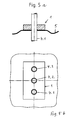
- Figures 5a and 5b show an embodiment which is quite similar to that of Figures 4a and 4b.
- the wall 5 consists of a film or a membrane, the z. B. made of rubber or plastic.
- a line 4 is passed through a gel body 1 and through a container wall 5.
- a line 4 is passed through a gel body 1, in which it has been pierced, in the direction from left to right.
- Gel body 1 sits in a receiving sleeve 6.
- the receiving sleeve 6 is enclosed by a rubber ring 7.
- Rubber ring 7 is enclosed by a bushing 8.
- Rubber ring 8 can be compressed by tightening several screws 9 in the axial direction, wherein it expands in the radial direction and thus firmly clamps the receiving sleeve 6.
- the socket 8 one can also imagine a wall of a building, which is provided with a bore for introducing the rubber ring.
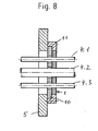
- FIG. 8 shows a further embodiment.
- a gel body 1 is provided, again constructed of a gel core 1.1, sandwiched between a gel-own skin 1.2 and a gel-own skin 1.3.
- a retaining ring 11 is fixed to the wall 5. It encloses the support plate 10 by abutting on its peripheral surface and on the peripheral region of its one side surface. At the same time he encloses the gel body.
- the embodiment according to FIG. 9 is particularly interesting.
- This again shows a line 4, a gel body 1 with gel core 1.1 and gel-own skin 1.2 and 1.3 and a container with container wall 5.
- the special feature of this embodiment is a cladding tube 12.
- To mount the entire assembly is carried out as follows: gel body 1 is placed on one side of the wall 5 and at this fixed, for example by gluing. Then, the cladding tube 12 is pushed or pushed from the right to the left by the gel body 1. Now, the line 4 is passed through the cladding tube 12. Then, the cladding tube 12 can be pulled out of the gel body 1 and also from the wall 5. Due to the elasticity of the gel material, the gel body shrinks so that it reliably seals the conduit 4.
- the cladding tube 12 can be used in this way in succession in several assembly operations.
- the gel body 1 is glued to the wall.
- one side of the gel body 1, formed according to the invention from a skin adjoins a collar 6.1 of the receiving sleeve 6 and is glued to this collar.
- the gel body 1 is adhesively bonded to the support plate 10.
- the bondability of gel bodies according to the invention is a great further advantage of the embodiment according to the invention. Without a skin namely sticking is not or only with difficulty possible.
- the gel body can be easily and reliably adhered to another surface with the side surface formed by the skin, e.g. B. on a container wall.
- the skin used is a separate skin which is applied to a gel core, polyuritan films have proven favorable.
- the skin may also be loose on the gel core.
Landscapes
- Engineering & Computer Science (AREA)
- Architecture (AREA)
- Civil Engineering (AREA)
- Structural Engineering (AREA)
- Building Environments (AREA)
- Sealing Using Fluids, Sealing Without Contact, And Removal Of Oil (AREA)
- Tents Or Canopies (AREA)
- Infusion, Injection, And Reservoir Apparatuses (AREA)
Abstract
Description
Die Erfindung betrifft eine Dichtungsvorrichtung, mit welcher zwei Räume gegeneinander abgetrennt oder abgegrenzt werden können.The invention relates to a sealing device with which two spaces can be separated or demarcated from each other.
Solche Vorrichtungen werden bei sogenannten Hauseinführungskombinationen angewandt. Diese werden dann eingesetzt, wenn eine Leitung durch eine Wand hindurchgeführt wird. Die Wand ist beispielsweise die Außenwand eines Hauses. Der eine der beiden Räume ist dann ein Innenraum des Hauses, und der andere Raum ist die äußere Umgebung. Die Wand weist eine Bohrung auf, die gegenüber dem Querschnitt der Leitung Übermaß hat, so dass zwischen der Leitung und der Laibung der Bohrung ein Ringraum verbleibt. Der Ringraum muss ausgefüllt werden, da er sonst eine leitende Verbindung zwischen den beiden Räumen darstellen würde, was unerwünscht ist. Der Ringraum wird ausgefüllt mit einem elastischen Körper, beispielsweise mit einem Ringkörper aus Gummi. Der Ringkörper aus Gummi umschließt die Leitung und liegt seinerseits selbst mit seiner äußeren Mantelfläche an der Laibung der Bohrung an. Durch axiales Stauchen wird der Gummi-Ringkörper an die Laibung der Bohrung angepresst.Such devices are used in so-called home introduction combinations. These are used when a pipe is passed through a wall. For example, the wall is the outer wall of a house. One of the two rooms is then an interior of the house, and the other room is the external environment. The wall has a bore which is oversized relative to the cross-section of the conduit so that an annulus remains between the conduit and the soffit of the bore. The annulus must be filled in, otherwise it would be a conductive connection between the two rooms, which is undesirable. The annular space is filled with an elastic body, for example with a ring body made of rubber. The annular body made of rubber encloses the line and in turn is itself with its outer circumferential surface of the soffit of the bore. By axial compression of the rubber ring body is pressed against the soffit of the hole.
Zum Ausfüllen des Ringraumes kann aber auch eine Gelmasse verwendet werden. Dabei wird die Gelmasse in die Bohrung eingebracht. Die Gelmasse bildet sodann einen Gelpfropfen, der satt an der Laibung der Bohrung anliegt. Sodann wird die Leitung durch die Gelmasse hindurchgestoßen. Die Gelmasse umschließt dann die Leitung. Damit ist zum einen die Leitung in der Bohrung fixiert, und zum anderen ist auch eine Abtrennung oder Abgrenzung zwischen den beiden Räumen hergestellt.To fill the annulus but also a gel mass can be used. The gel mass is introduced into the bore. The gel mass then forms a gel plug, which fits snugly against the soffit of the bore. Then the line is pushed through the gel mass. The gel mass then encloses the line. Thus, on the one hand, the line is fixed in the bore, and on the other hand, a separation or delimitation between the two spaces is made.
Das Einbringen einer Gelmasse hat somit den Vorteil der großen Einfachheit. Es hat jedoch den folgenden Nachteil: Stößt man die Leitung durch die Gelmasse hindurch, so bleibt die Gelmasse an der äußeren Mantelfläche der Leitung kleben, und es wird ein Teil der Gelmasse von der Leitung bei dessen axialer Durchstoßbewegung mitgeschleppt. Dies ist deshalb unerwünscht, weil damit dem Gelpfropfen Gelmasse entzogen wird, so dass nicht mehr genügend Gelmasse in der Bohrung vorhanden ist und damit auch kein zuverlässiges dichtes und festes Einspannen der Leitung in der Bohrung gewährleistet ist. Der Mitnahmeeffekt kann sogar so weit gehen, dass der gesamte Gelpfropfen bei der Bewegung des Leiters durch die Bohrung hindurch aus der Bohrung herausgezogen wird.The introduction of a gel mass thus has the advantage of great simplicity. However, it has the following disadvantage: If you push the line through the gel mass, then the gel mass sticks to the outer surface of the line, and it will be a part of the gel mass of the line at its axial Puncture entrained. This is undesirable because it is removed from the Gelpfropfen gel mass, so that not enough gel mass is present in the bore and thus no reliable tight and tight clamping of the line is guaranteed in the hole. The entrainment effect may even go so far that the entire gel plug is pulled out of the bore during the movement of the conductor through the bore.
Man könnte daran denken, auf der Austrittsseite des Gelpfropfens, das heißt dort, wo die Leitung austritt, eine Platte aus Metall aufzubringen, mit einer Bohrung zum Hindurchführen der Leitung. Jedoch müsste die Bohrung der Metallplatte gegenüber der Leitung ein gewisses Übermaß aufweisen. Es entstünde somit ein Ringspalt, durch den wiederum Gel austritt, so dass das Problem nach wie vor bestünde.One might think of applying a plate of metal on the exit side of the gel drop, that is, where the conduit exits, with a bore for passing the conduit. However, the bore of the metal plate would have to the line a certain excess. It would thus create an annular gap through which in turn gel emerges, so that the problem still existed.
Der Erfindung liegt die Aufgabe zugrunde, eine Vorrichtung gemäß dem Oberbegriff von Anspruch 1 derart zu gestalten, dass die Vorteile von Gelmaterial erhalten bleiben, die Nachteile aber vermieden werden. Es soll somit verhindert werden, dass Gelmasse beim Hindurchstoßen einer Leitung in Bewegungsrichtung der Leitung mitgeschleppt wird.The invention has for its object to design a device according to the preamble of
Diese Aufgabe wird durch die kennzeichnenden Merkmale von Anspruch 1 gelöst. Dem gemäß wird die Gelmasse wenigstens auf einer ihrer Grenzflächen mit einer Haut versehen, insbesondere auf jener Grenzfläche, aus der die Leitung beim Hindurchstoßen aus der Gelmasse austritt. Die Haut verhindert ein Mitschleppen von Gelmasse über diese Grenzfläche hinaus.This object is solved by the characterizing features of
Dies bedeutet natürlich, dass die Haut eine gewisse Elastizität oder Festigkeit oder Zähigkeit oder Reißfestigkeit haben muss. Das Material der Haut muss - genauso wie die Gelmasse - das Bestreben haben, beim Durchstoßen einer Leitung ihre ursprüngliche Form beizubehalten, somit die Leitung fortwährend eng umschließen, und damit verhindern, dass Gelteilchen von der Mantelfläche der Leitung mitgeschleppt werden.This of course means that the skin must have some elasticity or strength or toughness or tear resistance. The material of the skin, like the gel mass, must endeavor to maintain its original shape when piercing a conduit, thus keeping the conduit tight enclose, and thus prevent gel particles are dragged from the outer surface of the line.
Als Hautmaterial kommen zahlreiche Werkstoffe in Betracht. So könnte beispielsweise eine Gummihaut vorgesehen werden. Auch käme eine Folie in Betracht, so wie beispielsweise bei Gartenteichen verwendet. Ideal aber ist eine gel-eigene Haut, das heißt eine Haut, die wiederum aus einem Gel besteht, vielleicht aus demselben Gel, wie die Hauptmasse des Gelkörpers.As skin material numerous materials come into consideration. For example, a rubber skin could be provided. Also, a film would be considered, as used for example in garden ponds. Ideally, however, is a gel-own skin, that is, a skin, which in turn consists of a gel, perhaps of the same gel as the main mass of the gel body.
Auf jeden Fall muss die Haut mit dem (übrigen) Gelkörper innig verbunden sein, so dass sie am Haupt-Gelkörper verbleibt und nicht etwa durch Reibung an der Mantelfläche der Leitung mitgeschleppt wird.In any case, the skin must be intimately connected to the (remaining) gel body, so that it remains on the main gel body and not dragged by friction on the lateral surface of the pipe.
Die gel-eigene Haut kann durch physikalische oder chemische Einwirkung gebildet werden, so dass man sie gar nicht als Fremdkörper identifizieren kann.The gel-own skin can be formed by physical or chemical action, so that one can not identify it as a foreign body.
Die Haut muss sich nicht unbedingt über die gesamte Grenzfläche des Körpers hinwegerstrecken. Die Hauptsache ist, dass sie sich dort befindet, wo eine Leitung durch den Körper hindurchgestoßen wird. Im Extremfall kann die Haut lediglich in einem Ringbereich die Leitung umschließen, das heißt selbst die Gestalt eines Ringes haben, der natürlich mit dem übrigen Gelkörper untrennbar verbunden oder mit diesem einteilig ist.The skin does not necessarily extend over the entire interface of the body. The main thing is that it is where a wire is pushed through the body. In extreme cases, the skin can only enclose the line in a ring area, ie even have the shape of a ring, which is of course inseparably connected to the rest of the gel body or is integral therewith.
Die Erfindung ist anhand der Zeichnung näher erläutert. Darin ist im Einzelnen folgendes dargestellt:
Figur 1- zeigt einen Körper, durch den ein langgestreckter Körper, beispielsweise ein Stab, hindurchgestoßen werden soll, und zwar vor dem Hindurchstoßen des Stabes.
- Figur 2
- zeigt den Gegenstand von
Figur 1 mit dem Stab im Stadium des Hindurchstoßens. - Figur 3
- zeigt den Gegenstand von
Figur 1 nach dem Hindurchstoßen und Hindurchführen des Stabes gemäß Figur 2. - Figur 4a
- veranschaulicht einen weiteren Anwendungsfall, bei welchem eine Leitung durch einen Gelkörper sowie durch eine Behälterwand hindurchgeführt ist.
- Figur 4b
- zeigt den Gegenstand von
Figur 1 in einer Draufsicht mit geschnittenen Leitungen. - Figur 5a
- zeigt eine weitere Anwendungsform ähnlich jener gemäß Figur 4a.
- Figur 5b
- zeigt den Gegenstand von Figur 5a in einer Draufsicht, wiederum mit geschnittenen Leitungen.
- Figur 6a
- zeigt einen Behälter, durch dessen eine Wand eine Leitung hindurchgeführt ist.
- Figur 6b
- zeigt einen Horizontalschnitt durch den Gegenstand von Figur 6a.
- Figur 7
- zeigt eine sogenannte Hauseinführungskombination in einem Vertikalschnitt.
Figur 8- zeigt eine Wandung, durch welche drei Leitungen hindurchgeführt sind.
Figur 9- zeigt eine Anwendung mit einer Wandung, durch welche eine Stützhülse hindurchgeführt ist, die ihrerseits eine Leitung umschließt.
- FIG. 1
- shows a body through which an elongated body, such as a rod, is to be pushed, prior to the passage of the rod.
- FIG. 2
- shows the article of Figure 1 with the bar in the piercing state.
- FIG. 3
- 1 shows the article of FIG. 1 after the passage of the rod according to FIG. 2.
- FIG. 4a
- illustrates another application in which a conduit is passed through a gel body and through a container wall.
- FIG. 4b
- shows the article of Figure 1 in a plan view with cut lines.
- FIG. 5a
- shows a further embodiment similar to that of Figure 4a.
- FIG. 5b
- shows the subject of Figure 5a in a plan view, again with cut lines.
- FIG. 6a
- shows a container through whose wall a conduit is passed.
- FIG. 6b
- shows a horizontal section through the subject of Figure 6a.
- FIG. 7
- shows a so-called house introduction combination in a vertical section.
- FIG. 8
- shows a wall through which three lines are passed.
- FIG. 9
- shows an application with a wall through which a support sleeve is passed, which in turn encloses a conduit.
In Figur 1 erkennt man einen Gelkörper 1. Dieser umfasst einen Gelkern 1.1, ferner eine gel-eigene Haut 1.2 auf der einen Seite und eine gel-eigene Haut 1.3 auf der anderen Seite des Gelkerns 1.1.FIG. 1 shows a
Unter der Bezeichnung "Gel" wird ein chemisch oder physikalisch verknüpftes Polymernetzwerk verstanden, welches in einem Medium in beliebigem Stoffzustand gequollen ist. Es besteht aus mindestens zwei Komponenten, die mehr oder weniger kontinuierlich im vorhandenen Volumen verteilt sind.The term "gel" is understood to mean a chemically or physically linked polymer network which has swollen in a medium in any state of matter. It consists of at least two components, which are distributed more or less continuously in the existing volume.
Durch die Art der Verknüpfungspunkte, die in einem Netzwerk vorliegen, stellt man unterschiedliches Quellverhalten von Gelen fest:
- Bei physikalisch verknüpften Netzwerken wird im Allgemeinen ein Gel-Sol-Übergang festgestellt. In Abhängigkeit von der Temperatur und/oder der Quellmittelmenge bildet das Polymer ein Gel, kann aber auch ohne Zerstörung der einzelnen Polymerketten in den Solzustand gebracht werden. Das Polymer-Quellmittel-System bildet dann eine Lösung. Dieser Vorgang ist reversibel, weshalb diese Gele auch als "thermoreversible Gele" bezeichnet werden.
- Bei chemisch verknüpften Netzwerken hingegen ist ein Gel-Sol-Übergang lediglich unter irreversiblem Abbau der Netzwerkstruktur zu erreichen. Das Netzwerk ist nur bis zu einem bestimmten Grad in der Lage, Quellmittel aufzunehmen, dem sogenannten Sättigungs- oder Gleichgewichts-Quellungsgrad.
- In physically linked networks, a gel-sol transition is generally detected. Depending on the temperature and / or the amount of swelling agent, the polymer forms a gel, but can also be brought into the sol state without destroying the individual polymer chains. The polymer swelling agent system then forms a solution. This process is reversible, which is why these gels are also referred to as "thermoreversible gels".
- In chemically linked networks, however, a gel-sol transition can only be achieved by irreversible degradation of the network structure. The network is only able to absorb swelling agents to a certain degree, the so-called saturation or equilibrium degree of swelling.
Im Gelzustand eines chemisch verknüpften Netzwerkes bleibt die äußere Form des Netzwerkes sowie die Gummi-Elastizität beibehalten. Physikalisch betrachtet besitzt ein Gel sowohl elastische als auch Viskoseeigenschaften. Es ist somit viskoelastisch. Der Gelzustand wird auch bei glasig erstarrten Netzwerken unterhalb ihrer Glastemperatur mit einem geeigneten Quellmittel gebildet.In the gel state of a chemically linked network, the outer shape of the network as well as the rubber elasticity are retained. Physically, a gel has both elastic and viscous properties. It is thus viscoelastic. The gel state is also formed in glassy solidified networks below their glass transition temperature with a suitable swelling agent.
In Figur 2 erkennt man wiederum den Gelkörper 1 gemäß Figur 1 mit einem hindurchgestoßenen Stab 4. Statt des Stabes könnte auch eine Leitung hindurchgeführt sein. Der Pfeil gibt die Richtung des Hindurchstoßens an.FIG. 2 again shows the
Wie man sieht, ist sowohl die Gelhaut 1.2 als auch die Gelhaut 1.3 vom Stab 4 um ein gewisses Maß mitgenommen - siehe an beiden Gelhäuten den Meniskus. Die Mitnahme ist jedoch gering, verglichen mit einem Gelkörper ohne eine solche Haut. Der Grund liegt darin, dass die Gelhaut 1.2 beziehungsweise 1.4 derart stramm den Stab 4 umschließt, dass Gel aus dem Gelkern nicht in nennenswertem Maße von der Mantelfläche des Stabes 4 mitgeschleppt werden kann. Das Material der Gelhaut 1.2 beziehungsweise 1.3 kann eine höhere elastische Kraft aufbringen, als das Material des Gelkerns 1.1.As you can see, both the gel-skin 1.2 and the gel-skin 1.3 are taken along by the
Figur 3 veranschaulicht jenen Zustand, bei welchem der Stab 4 durch den Gelkörper 1 völlig hindurchgeführt und herausgeführt ist. Man erkennt noch einen Lunker 1.4, dessen Durchmesser jedoch äußerst gering ist. Der Lunker 1.4 verschwindet jedoch nach kurzer Zeit völlig oder fast völlig, insbesondere dann, wenn in radialer Richtung Druck auf den Gekörper 1 ausgeübt wird.Figure 3 illustrates the state in which the
Bei der Ausführungsform gemäß der Figuren 4a und 4b sind drei Rohrleitungen 4.1, 4.2 und 4.3 durch einen Gelkörper 1 hindurchgeführt. Der Gelkörper hat die Gestalt eines Quaders. Er liegt auf einer Wand 5 auf. Die Wand 5 kann aus einem dünnen Blech bestehen. Gelkörper 1 umfasst wiederum einen Gelkern 1.1 sowie eine gel-eigene Haut 1.2, die die eine Seitenfläche des Gelkörpers 1 bildet, und eine gel-eigene Haut 1.3, die die andere Seite bildet. Dabei könnte es ausreichen, nur eine einzige Seite des Gelkerns 1.1 mit einer gel-eigenen Haut zu versehen, nämlich die Unterseite, auf welcher die Leitungen 4.1, 4.2, 4.3 beim Durchstoßen des Gelkörpers 1 austreten.In the embodiment according to FIGS. 4a and 4b, three pipes 4.1, 4.2 and 4.3 are passed through a
Die Wand 5 weist eine Bohrung 5.1 auf.The
Figuren 5a und 5b zeigen eine Ausführungsform, die ganz ähnlich wie jene gemäß der Figuren 4a und 4b ist. Die Wand 5 besteht hierbei aus einer Folie oder einer Membran, die z. B. aus Gummi oder Kunststoff besteht.Figures 5a and 5b show an embodiment which is quite similar to that of Figures 4a and 4b. The
In Figur 6 ist wiederum eine Leitung 4 durch einen Gelkörper 1 und durch eine Behälterwand 5 hindurchgeführt.In FIG. 6, in turn, a
Bei der Ausführungsform gemäß Figur 7 erkennt man im Einzelnen folgendes: Eine Leitung 4 ist durch einen Gelkörper 1 hindurchgeführt, indem dieser durchstoßen wurde, und zwar in Richtung von links nach rechts. Gelkörper 1 sitzt in einer Aufnahmehülse 6. Die Aufnahmehülse 6 ist von einem Gummiring 7 umschlossen. Gummiring 7 ist von einer Buchse 8 umschlossen. Gummiring 8 lässt sich durch Anziehen von mehreren Schrauben 9 in Axialrichtung stauchen, wobei er sich in radialer Richtung ausdehnt und damit die Aufnahmehülse 6 fest einspannt. Statt der Buchse 8 kann man sich auch eine Wand eines Gebäudes vorstellen, die mit einer Bohrung zum Einbringen des Gummiringes versehen ist.In detail, in the embodiment according to FIG. 7, a
Figur 8 zeigt eine weitere Ausführungsform. Hierbei sind wiederum drei Leitungen 4.1, 4.2 und 4.3 unterschiedlicher Durchmesser durch eine Bohrung in einer Wand 5 hindurchgeführt. Dabei ist ein Gelkörper 1 vorgesehen, wiederum aufgebaut aus einem Gelkern 1.1, sandwichartig eingeschlossen zwischen einer gel-eigenen Haut 1.2 und einer gel-eigenen Haut 1.3. Zwischen Gelkörper.1 und Wand 5 befindet sich eine perforierte Stützplatte 10. Ein Haltering 11 ist an der Wand 5 fixiert. Er umschließt die Stützplatte 10, indem er an deren Umfangsfläche sowie am Umfangsbereich ihrer einen Seitenfläche anliegt. Gleichzeitig umschließt er den Gelkörper 1.FIG. 8 shows a further embodiment. Here again three lines 4.1, 4.2 and 4.3 of different diameters are passed through a hole in a
Die Ausführungsform gemäß Figur 9 ist besonders interessant. Man erkennt hierbei wiederum eine Leitung 4, einen Gelkörper 1 mit Gelkern 1.1 und gel-eigener Haut 1.2 und 1.3 sowie einen Behälter mit Behälterwand 5. Das Besondere an dieser Ausführungsform ist ein Hüllrohr 12. Zum Montieren der gesamten Baueinheit geht man dabei wie folgt vor: Gelkörper 1 wird auf der einen Seite der Wand 5 aufgelegt und an dieser fixiert, beispielsweise durch Verkleben. Sodann wird das Hüllrohr 12 von rechts her nach links durch den Gelkörper 1 hindurchgestoßen oder geschoben. Nunmehr wird die Leitung 4 durch das Hüllrohr 12 hindurchgeführt. Sodann kann das Hüllrohr 12 aus dem Gelkörper 1 und auch aus der Wand 5 herausgezogen werden. Aufgrund der Elastizität des Gelmaterials schrumpft der Gelkörper zusammen, so dass er zuverlässig dichtend die Leitung 4 umschließt. Das Hüllrohr 12 kann auf diese Weise bei mehreren Montagevorgängen nacheinander verwendet werden.The embodiment according to FIG. 9 is particularly interesting. This again shows a
Bei den Ausführungsformen gemäß der Figuren 4.a und 4.b, 5.a und 5.b, 6 und 9 ist der Gelkörper 1 mit der Wand verklebt. Bei der Ausführungsform gemäß Figur 7 liegt die eine Seite des Gelkörpers 1, erfindungsgemäß aus einer Haut gebildet, an einem Bund 6.1 der Aufnahmehülse 6 an und ist mit diesem Bund verklebt.In the embodiments according to FIGS. 4.a and 4.b, 5.a and 5.b, 6 and 9, the
Bei der Ausführungsform gemäß Figur 8 ist der Gelkörper 1 mit der Stützplatte 10 verklebt.In the embodiment according to FIG. 8, the
Die Verklebbarkeit von erfindungsgemäßen Gelkörpern ist ein großer weiterer Vorteil der erfindungsgemäßen Ausführungsform. Ohne eine Haut ist nämlich ein Verkleben nicht oder nur schwer möglich. Der Gelkörper lässt sich mit jener Seitenfläche, die aus der Haut gebildet wird, leicht und zuverlässig an einer anderen Fläche festkleben, z. B. an einer Behälterwand.The bondability of gel bodies according to the invention is a great further advantage of the embodiment according to the invention. Without a skin namely sticking is not or only with difficulty possible. The gel body can be easily and reliably adhered to another surface with the side surface formed by the skin, e.g. B. on a container wall.
Besonders günstige Gelformen sind formstabile Polyurethan-Gele. Diese zeichnen sich unter anderem durch eine besonders hohe Dehnung aus. Ihre Zugfestigkeit kann in den folgenden Grenzen gewählt werden:
- Weich: 140 bis 200 kPa
- Mittel: 200 bis 300 kPa
- Hart: 300 bis 400 kPa.
- Soft: 140 to 200 kPa
- Average: 200 to 300 kPa
- Hard: 300 to 400 kPa.
Verwendet man als Haut eine separate Haut, die auf einen Gelkern aufgebracht wird, so haben sich Folien aus Polyuritan als günstig erwiesen. Die Haut kann auch auf den Gelkern lose aufgelegt sein.If the skin used is a separate skin which is applied to a gel core, polyuritan films have proven favorable. The skin may also be loose on the gel core.
Besonders vorteilhaft ist die Anwendung einer erfindungsgemäßen Vorrichtung bei einer sogenannten Hauseinführungskombination, so wie eingangs beschrieben.Particularly advantageous is the use of a device according to the invention in a so-called house introduction combination, as described above.
- 11
- Gelkörpergel body
- 1.11.1
- Gelkerngel core
- 1.21.2
- gel-eigene Hautgel-own skin
- 1.31.3
- gel-eigene Hautgel-own skin
- 1.41.4
- LunkerLunker
- 44
- Leitung oder stabförmiger KörperConduction or rod-shaped body
- 4.14.1
- Leitungmanagement
- 4.24.2
- Leitungmanagement
- 4.34.3
- Leitungmanagement
- 55
- Behälterwandcontainer wall
- 5.15.1
- Bohrungdrilling
- 66
- Aufnahmehülsereceiving sleeve
- 77
- Gummiringrubber ring
- 88th
- BuchseRifle
- 99
- Schraubescrew
- 1010
- Stützplattesupport plate
- 1111
- Halteringretaining ring
- 1212
- Hüllrohrcladding tube
Claims (8)
Priority Applications (1)
| Application Number | Priority Date | Filing Date | Title |
|---|---|---|---|
| PL05020626T PL1643604T3 (en) | 2004-10-02 | 2005-09-22 | Device for gas or fluid sealing between two adjacent rooms |
Applications Claiming Priority (1)
| Application Number | Priority Date | Filing Date | Title |
|---|---|---|---|
| DE102004048154A DE102004048154A1 (en) | 2004-10-02 | 2004-10-02 | Device for liquid-tight or gas-tight mutual delimitation of two rooms |
Publications (2)
| Publication Number | Publication Date |
|---|---|
| EP1643604A1 true EP1643604A1 (en) | 2006-04-05 |
| EP1643604B1 EP1643604B1 (en) | 2007-06-06 |
Family
ID=35609724
Family Applications (1)
| Application Number | Title | Priority Date | Filing Date |
|---|---|---|---|
| EP05020626A Not-in-force EP1643604B1 (en) | 2004-10-02 | 2005-09-22 | Device for gas or fluid sealing between two adjacent rooms |
Country Status (5)
| Country | Link |
|---|---|
| EP (1) | EP1643604B1 (en) |
| AT (1) | ATE364248T1 (en) |
| DE (2) | DE102004048154A1 (en) |
| ES (1) | ES2287851T3 (en) |
| PL (1) | PL1643604T3 (en) |
Cited By (5)
| Publication number | Priority date | Publication date | Assignee | Title |
|---|---|---|---|---|
| EP1961798A1 (en) * | 2007-02-23 | 2008-08-27 | Hauff-Technik GmbH & Co. KG | combination substance and applications for such a substance |
| WO2010146320A1 (en) * | 2009-06-19 | 2010-12-23 | Tissage Et Enduction Serge Ferrari Sa | Device for forming a sealed partition, to be mounted on a wall, and enclosure for receiving at least one electric apparatus, including such a device |
| WO2012022379A1 (en) * | 2010-08-18 | 2012-02-23 | Dresser Wayne Ab | New sealing device |
| DE202012001199U1 (en) * | 2012-02-07 | 2013-05-08 | Doyma Gmbh & Co | Sealing device with sealing body and sealant |
| DE102018113247A1 (en) * | 2018-06-04 | 2019-12-05 | Reichle & De-Massari Ag | sealing device |
Families Citing this family (3)
| Publication number | Priority date | Publication date | Assignee | Title |
|---|---|---|---|---|
| DE102008008034A1 (en) | 2008-02-05 | 2009-08-06 | Gt Elektrotechnische Produkte Gmbh | Polyurethane gel obtained by mixing polyether alcohols, a diisocyanate, a triisocyanate and additives, in the presence of a catalyst, useful in prosthetics, sports area (bicycle saddles) and cable penetrations |
| DE202008018346U1 (en) | 2008-02-05 | 2013-02-14 | Gt Elektrotechnische Produkte Gmbh | Multifunctional polyurethane gel |
| EP2481765B1 (en) | 2011-01-31 | 2014-04-02 | GT Elektrotechnische Produkte GmbH | Cable connector on the basis of elastic polymer-foam-gel compounds with adjustable contact pressure |
Citations (1)
| Publication number | Priority date | Publication date | Assignee | Title |
|---|---|---|---|---|
| US4662692A (en) * | 1985-05-02 | 1987-05-05 | Raychem Corp. | Sealing member |
Family Cites Families (5)
| Publication number | Priority date | Publication date | Assignee | Title |
|---|---|---|---|---|
| US5360945A (en) * | 1991-05-01 | 1994-11-01 | Raychem Corporation | Cable seal |
| US5529508A (en) * | 1994-04-01 | 1996-06-25 | Raychem Corporation | Sealing member |
| US5934922A (en) * | 1997-02-07 | 1999-08-10 | Raychem Corporation | Sealing member |
| DE19748631A1 (en) * | 1997-11-04 | 1999-05-06 | Fraunhofer Ges Forschung | Safety seal for liquid systems using swellable polymers |
| DE19915667A1 (en) * | 1999-04-07 | 2000-10-19 | Fraunhofer Ges Forschung | Sealing bushings and procedures for sealing bushings |
-
2004
- 2004-10-02 DE DE102004048154A patent/DE102004048154A1/en not_active Withdrawn
-
2005
- 2005-09-22 EP EP05020626A patent/EP1643604B1/en not_active Not-in-force
- 2005-09-22 ES ES05020626T patent/ES2287851T3/en active Active
- 2005-09-22 DE DE502005000814T patent/DE502005000814D1/en active Active
- 2005-09-22 AT AT05020626T patent/ATE364248T1/en active
- 2005-09-22 PL PL05020626T patent/PL1643604T3/en unknown
Patent Citations (1)
| Publication number | Priority date | Publication date | Assignee | Title |
|---|---|---|---|---|
| US4662692A (en) * | 1985-05-02 | 1987-05-05 | Raychem Corp. | Sealing member |
Cited By (12)
| Publication number | Priority date | Publication date | Assignee | Title |
|---|---|---|---|---|
| EP1961798A1 (en) * | 2007-02-23 | 2008-08-27 | Hauff-Technik GmbH & Co. KG | combination substance and applications for such a substance |
| WO2010146320A1 (en) * | 2009-06-19 | 2010-12-23 | Tissage Et Enduction Serge Ferrari Sa | Device for forming a sealed partition, to be mounted on a wall, and enclosure for receiving at least one electric apparatus, including such a device |
| FR2947110A1 (en) * | 2009-06-19 | 2010-12-24 | Ferrari S Tissage & Enduct Sa | DEVICE FOR REPORTING ON A WALL FOR FORMING A WATERPROOF WALL AND ENVELOPE EQUIPPED WITH SUCH A DEVICE AND FOR LODGING AT LEAST ONE ELECTRICAL DEVICE |
| CN102484363A (en) * | 2009-06-19 | 2012-05-30 | 赛尔吉法拉利简易股份公司 | Device For Forming A Sealed Partition, To Be Mounted On A Wall, And Enclosure For Receiving At Least One Electric Apparatus, Including Such A Device |
| CN102484363B (en) * | 2009-06-19 | 2015-07-15 | 赛尔吉法拉利简易股份公司 | Device For Forming A Sealed Partition, To Be Mounted On A Wall, And Enclosure For Receiving At Least One Electric Apparatus, Including Such A Device |
| WO2012022379A1 (en) * | 2010-08-18 | 2012-02-23 | Dresser Wayne Ab | New sealing device |
| DE202012001199U1 (en) * | 2012-02-07 | 2013-05-08 | Doyma Gmbh & Co | Sealing device with sealing body and sealant |
| DE102013202002B4 (en) * | 2012-02-07 | 2018-05-30 | Doyma Gmbh & Co | Sealing device with sealing body and sealant and method for sealing a pipe against a breakthrough in a wall portion |
| DE102013022326B3 (en) | 2012-02-07 | 2023-04-13 | Doyma Gmbh & Co | Sealing device with sealing body and sealing compound |
| DE102013022528B4 (en) | 2012-02-07 | 2023-11-30 | Doyma Gmbh & Co | Sealing device with sealing body and sealing compound and method for sealing a pipe against a breakthrough in a wall section |
| DE102018113247A1 (en) * | 2018-06-04 | 2019-12-05 | Reichle & De-Massari Ag | sealing device |
| EP3940904A1 (en) | 2018-06-04 | 2022-01-19 | Reichle & De-Massari AG | Seal device |
Also Published As
| Publication number | Publication date |
|---|---|
| PL1643604T3 (en) | 2007-10-31 |
| EP1643604B1 (en) | 2007-06-06 |
| DE102004048154A1 (en) | 2006-04-13 |
| ES2287851T3 (en) | 2007-12-16 |
| DE502005000814D1 (en) | 2007-07-19 |
| ATE364248T1 (en) | 2007-06-15 |
Similar Documents
| Publication | Publication Date | Title |
|---|---|---|
| EP1643604B1 (en) | Device for gas or fluid sealing between two adjacent rooms | |
| DE102006015847B4 (en) | Sealing pack for insertion into a wall opening | |
| EP0909915A2 (en) | Seal for coupling and connecting means | |
| DE102004035180A1 (en) | Pipe connection, in particular suitable for use in plumbing, comprising pre-inserted sealing material and flexible protection cover | |
| DE1925171A1 (en) | Connection device or coupling | |
| DE10207201A1 (en) | Connecting sleeve fits over pipe and has circumferential groove containing metal clamping ring | |
| DE3613420C2 (en) | ||
| EP3032146A1 (en) | Seal element | |
| EP2075404A2 (en) | Device for applying mortar | |
| EP1598589A2 (en) | Fire-proof material | |
| DE8230585U1 (en) | Device for the termination of cable ducts | |
| DE102006004828A1 (en) | Plastic tube for passing through heating or cooling medium, has external diameter of up to five millimeters, where section thickness of tube is partly strengthened in terminal area, and inner diameter of tube in terminal area is smaller | |
| EP1068468B1 (en) | Sealing element for piping | |
| EP3619447B1 (en) | Flange seal system and assembly method | |
| DE102016224014A1 (en) | Clamping device for introducing a bias in a tubular hollow profile | |
| DE3102350A1 (en) | Multilayer pipe of thermoplastic | |
| DE3603056C2 (en) | Pipe assembly from a plurality of plastic pipes | |
| DE2259571A1 (en) | PIPE CONNECTION WITH SEAL | |
| EP1012417A1 (en) | Compression tubing for producing water-impermeable or only slightly water-permeable, gastight and/or friction-locked building joints | |
| DE2119057A1 (en) | Arrangement for sealing cables at the point of entry of fittings | |
| DE102020101722A1 (en) | Sealing set for cable outlets | |
| DE10130050A1 (en) | Tensioning and/or sealing ring, for use in nuclear plants and aircraft, is produced by placing an elastic separating wall in a mould at normal temperature, and filling material into the mold | |
| EP1705301B1 (en) | Injection or pressure hose and procedure for sealing construction joints between building structures | |
| DE3412002C1 (en) | Process for the preparation of polyurethane material which can be crosslinked by electron beams, and the use thereof for electrical applications | |
| AT395904B (en) | PIPE CONNECTOR FOR USE IN THE PRODUCTION OF THERMALLY INSULATED PIPES |
Legal Events
| Date | Code | Title | Description |
|---|---|---|---|
| PUAI | Public reference made under article 153(3) epc to a published international application that has entered the european phase |
Free format text: ORIGINAL CODE: 0009012 |
|
| AK | Designated contracting states |
Kind code of ref document: A1 Designated state(s): AT BE BG CH CY CZ DE DK EE ES FI FR GB GR HU IE IS IT LI LT LU LV MC NL PL PT RO SE SI SK TR |
|
| AX | Request for extension of the european patent |
Extension state: AL BA HR MK YU |
|
| 17P | Request for examination filed |
Effective date: 20060818 |
|
| GRAP | Despatch of communication of intention to grant a patent |
Free format text: ORIGINAL CODE: EPIDOSNIGR1 |
|
| AKX | Designation fees paid |
Designated state(s): AT BE BG CH CY CZ DE DK EE ES FI FR GB GR HU IE IS IT LI LT LU LV MC NL PL PT RO SE SI SK TR |
|
| GRAS | Grant fee paid |
Free format text: ORIGINAL CODE: EPIDOSNIGR3 |
|
| GRAA | (expected) grant |
Free format text: ORIGINAL CODE: 0009210 |
|
| AK | Designated contracting states |
Kind code of ref document: B1 Designated state(s): AT BE BG CH CY CZ DE DK EE ES FI FR GB GR HU IE IS IT LI LT LU LV MC NL PL PT RO SE SI SK TR |
|
| PG25 | Lapsed in a contracting state [announced via postgrant information from national office to epo] |
Ref country code: FI Free format text: LAPSE BECAUSE OF FAILURE TO SUBMIT A TRANSLATION OF THE DESCRIPTION OR TO PAY THE FEE WITHIN THE PRESCRIBED TIME-LIMIT Effective date: 20070606 |
|
| REG | Reference to a national code |
Ref country code: GB Ref legal event code: FG4D Free format text: NOT ENGLISH |
|
| REG | Reference to a national code |
Ref country code: CH Ref legal event code: EP |
|
| REG | Reference to a national code |
Ref country code: IE Ref legal event code: FG4D Free format text: LANGUAGE OF EP DOCUMENT: GERMAN |
|
| REF | Corresponds to: |
Ref document number: 502005000814 Country of ref document: DE Date of ref document: 20070719 Kind code of ref document: P |
|
| REG | Reference to a national code |
Ref country code: SE Ref legal event code: TRGR |
|
| GBT | Gb: translation of ep patent filed (gb section 77(6)(a)/1977) |
Effective date: 20070822 |
|
| REG | Reference to a national code |
Ref country code: PL Ref legal event code: T3 |
|
| ET | Fr: translation filed | ||
| REG | Reference to a national code |
Ref country code: ES Ref legal event code: FG2A Ref document number: 2287851 Country of ref document: ES Kind code of ref document: T3 |
|
| REG | Reference to a national code |
Ref country code: IE Ref legal event code: FD4D |
|
| PG25 | Lapsed in a contracting state [announced via postgrant information from national office to epo] |
Ref country code: PT Free format text: LAPSE BECAUSE OF FAILURE TO SUBMIT A TRANSLATION OF THE DESCRIPTION OR TO PAY THE FEE WITHIN THE PRESCRIBED TIME-LIMIT Effective date: 20071106 Ref country code: BG Free format text: LAPSE BECAUSE OF FAILURE TO SUBMIT A TRANSLATION OF THE DESCRIPTION OR TO PAY THE FEE WITHIN THE PRESCRIBED TIME-LIMIT Effective date: 20070906 Ref country code: CZ Free format text: LAPSE BECAUSE OF FAILURE TO SUBMIT A TRANSLATION OF THE DESCRIPTION OR TO PAY THE FEE WITHIN THE PRESCRIBED TIME-LIMIT Effective date: 20070606 Ref country code: SI Free format text: LAPSE BECAUSE OF FAILURE TO SUBMIT A TRANSLATION OF THE DESCRIPTION OR TO PAY THE FEE WITHIN THE PRESCRIBED TIME-LIMIT Effective date: 20070606 Ref country code: IS Free format text: LAPSE BECAUSE OF FAILURE TO SUBMIT A TRANSLATION OF THE DESCRIPTION OR TO PAY THE FEE WITHIN THE PRESCRIBED TIME-LIMIT Effective date: 20071006 Ref country code: IE Free format text: LAPSE BECAUSE OF FAILURE TO SUBMIT A TRANSLATION OF THE DESCRIPTION OR TO PAY THE FEE WITHIN THE PRESCRIBED TIME-LIMIT Effective date: 20070606 |
|
| PG25 | Lapsed in a contracting state [announced via postgrant information from national office to epo] |
Ref country code: LV Free format text: LAPSE BECAUSE OF FAILURE TO SUBMIT A TRANSLATION OF THE DESCRIPTION OR TO PAY THE FEE WITHIN THE PRESCRIBED TIME-LIMIT Effective date: 20070606 Ref country code: SK Free format text: LAPSE BECAUSE OF FAILURE TO SUBMIT A TRANSLATION OF THE DESCRIPTION OR TO PAY THE FEE WITHIN THE PRESCRIBED TIME-LIMIT Effective date: 20070606 Ref country code: LT Free format text: LAPSE BECAUSE OF FAILURE TO SUBMIT A TRANSLATION OF THE DESCRIPTION OR TO PAY THE FEE WITHIN THE PRESCRIBED TIME-LIMIT Effective date: 20070606 |
|
| PLBE | No opposition filed within time limit |
Free format text: ORIGINAL CODE: 0009261 |
|
| STAA | Information on the status of an ep patent application or granted ep patent |
Free format text: STATUS: NO OPPOSITION FILED WITHIN TIME LIMIT |
|
| PG25 | Lapsed in a contracting state [announced via postgrant information from national office to epo] |
Ref country code: MC Free format text: LAPSE BECAUSE OF NON-PAYMENT OF DUE FEES Effective date: 20070930 Ref country code: GR Free format text: LAPSE BECAUSE OF FAILURE TO SUBMIT A TRANSLATION OF THE DESCRIPTION OR TO PAY THE FEE WITHIN THE PRESCRIBED TIME-LIMIT Effective date: 20070907 Ref country code: DK Free format text: LAPSE BECAUSE OF FAILURE TO SUBMIT A TRANSLATION OF THE DESCRIPTION OR TO PAY THE FEE WITHIN THE PRESCRIBED TIME-LIMIT Effective date: 20070606 |
|
| 26N | No opposition filed |
Effective date: 20080307 |
|
| PG25 | Lapsed in a contracting state [announced via postgrant information from national office to epo] |
Ref country code: RO Free format text: LAPSE BECAUSE OF FAILURE TO SUBMIT A TRANSLATION OF THE DESCRIPTION OR TO PAY THE FEE WITHIN THE PRESCRIBED TIME-LIMIT Effective date: 20070606 |
|
| PG25 | Lapsed in a contracting state [announced via postgrant information from national office to epo] |
Ref country code: EE Free format text: LAPSE BECAUSE OF FAILURE TO SUBMIT A TRANSLATION OF THE DESCRIPTION OR TO PAY THE FEE WITHIN THE PRESCRIBED TIME-LIMIT Effective date: 20070606 |
|
| PG25 | Lapsed in a contracting state [announced via postgrant information from national office to epo] |
Ref country code: CY Free format text: LAPSE BECAUSE OF FAILURE TO SUBMIT A TRANSLATION OF THE DESCRIPTION OR TO PAY THE FEE WITHIN THE PRESCRIBED TIME-LIMIT Effective date: 20070606 |
|
| PG25 | Lapsed in a contracting state [announced via postgrant information from national office to epo] |
Ref country code: LU Free format text: LAPSE BECAUSE OF NON-PAYMENT OF DUE FEES Effective date: 20070922 |
|
| PG25 | Lapsed in a contracting state [announced via postgrant information from national office to epo] |
Ref country code: HU Free format text: LAPSE BECAUSE OF FAILURE TO SUBMIT A TRANSLATION OF THE DESCRIPTION OR TO PAY THE FEE WITHIN THE PRESCRIBED TIME-LIMIT Effective date: 20071207 |
|
| PGFP | Annual fee paid to national office [announced via postgrant information from national office to epo] |
Ref country code: ES Payment date: 20090917 Year of fee payment: 5 |
|
| PGFP | Annual fee paid to national office [announced via postgrant information from national office to epo] |
Ref country code: GB Payment date: 20090925 Year of fee payment: 5 Ref country code: SE Payment date: 20090921 Year of fee payment: 5 Ref country code: TR Payment date: 20090923 Year of fee payment: 5 |
|
| PGFP | Annual fee paid to national office [announced via postgrant information from national office to epo] |
Ref country code: BE Payment date: 20090923 Year of fee payment: 5 |
|
| BERE | Be: lapsed |
Owner name: HAUFF-TECHNIK G.M.B.H. & CO. KG Effective date: 20100930 |
|
| REG | Reference to a national code |
Ref country code: SE Ref legal event code: EUG |
|
| GBPC | Gb: european patent ceased through non-payment of renewal fee |
Effective date: 20100922 |
|
| PG25 | Lapsed in a contracting state [announced via postgrant information from national office to epo] |
Ref country code: BE Free format text: LAPSE BECAUSE OF NON-PAYMENT OF DUE FEES Effective date: 20100930 |
|
| PG25 | Lapsed in a contracting state [announced via postgrant information from national office to epo] |
Ref country code: GB Free format text: LAPSE BECAUSE OF NON-PAYMENT OF DUE FEES Effective date: 20100922 |
|
| REG | Reference to a national code |
Ref country code: ES Ref legal event code: FD2A Effective date: 20111019 |
|
| PGFP | Annual fee paid to national office [announced via postgrant information from national office to epo] |
Ref country code: CH Payment date: 20110926 Year of fee payment: 7 |
|
| PG25 | Lapsed in a contracting state [announced via postgrant information from national office to epo] |
Ref country code: ES Free format text: LAPSE BECAUSE OF NON-PAYMENT OF DUE FEES Effective date: 20100923 |
|
| PG25 | Lapsed in a contracting state [announced via postgrant information from national office to epo] |
Ref country code: SE Free format text: LAPSE BECAUSE OF NON-PAYMENT OF DUE FEES Effective date: 20100923 |
|
| PGFP | Annual fee paid to national office [announced via postgrant information from national office to epo] |
Ref country code: PL Payment date: 20120910 Year of fee payment: 8 |
|
| PGFP | Annual fee paid to national office [announced via postgrant information from national office to epo] |
Ref country code: IT Payment date: 20120925 Year of fee payment: 8 |
|
| PG25 | Lapsed in a contracting state [announced via postgrant information from national office to epo] |
Ref country code: TR Free format text: LAPSE BECAUSE OF NON-PAYMENT OF DUE FEES Effective date: 20100922 |
|
| PGFP | Annual fee paid to national office [announced via postgrant information from national office to epo] |
Ref country code: FR Payment date: 20121008 Year of fee payment: 8 Ref country code: NL Payment date: 20120920 Year of fee payment: 8 |
|
| PGFP | Annual fee paid to national office [announced via postgrant information from national office to epo] |
Ref country code: AT Payment date: 20120919 Year of fee payment: 8 |
|
| REG | Reference to a national code |
Ref country code: NL Ref legal event code: V1 Effective date: 20140401 |
|
| REG | Reference to a national code |
Ref country code: CH Ref legal event code: PL |
|
| REG | Reference to a national code |
Ref country code: AT Ref legal event code: MM01 Ref document number: 364248 Country of ref document: AT Kind code of ref document: T Effective date: 20130922 |
|
| REG | Reference to a national code |
Ref country code: FR Ref legal event code: ST Effective date: 20140530 |
|
| PG25 | Lapsed in a contracting state [announced via postgrant information from national office to epo] |
Ref country code: CH Free format text: LAPSE BECAUSE OF NON-PAYMENT OF DUE FEES Effective date: 20130930 Ref country code: LI Free format text: LAPSE BECAUSE OF NON-PAYMENT OF DUE FEES Effective date: 20130930 |
|
| PG25 | Lapsed in a contracting state [announced via postgrant information from national office to epo] |
Ref country code: IT Free format text: LAPSE BECAUSE OF NON-PAYMENT OF DUE FEES Effective date: 20130922 Ref country code: NL Free format text: LAPSE BECAUSE OF NON-PAYMENT OF DUE FEES Effective date: 20140401 Ref country code: AT Free format text: LAPSE BECAUSE OF NON-PAYMENT OF DUE FEES Effective date: 20130922 Ref country code: FR Free format text: LAPSE BECAUSE OF NON-PAYMENT OF DUE FEES Effective date: 20130930 |
|
| PG25 | Lapsed in a contracting state [announced via postgrant information from national office to epo] |
Ref country code: PL Free format text: LAPSE BECAUSE OF NON-PAYMENT OF DUE FEES Effective date: 20130922 |
|
| REG | Reference to a national code |
Ref country code: PL Ref legal event code: LAPE |
|
| REG | Reference to a national code |
Ref country code: DE Ref legal event code: R082 Ref document number: 502005000814 Country of ref document: DE Representative=s name: KOENIG SZYNKA TILMANN VON RENESSE PATENTANWAEL, DE |
|
| REG | Reference to a national code |
Ref country code: DE Ref legal event code: R081 Ref document number: 502005000814 Country of ref document: DE Owner name: HAUFF-TECHNIK GMBH & CO. KG, DE Free format text: FORMER OWNER: HAUFF-TECHNIK GMBH & CO KG, 89542 HERBRECHTINGEN, DE Effective date: 20150430 Ref country code: DE Ref legal event code: R082 Ref document number: 502005000814 Country of ref document: DE Representative=s name: KOENIG SZYNKA TILMANN VON RENESSE PATENTANWAEL, DE Effective date: 20150430 |
|
| PGFP | Annual fee paid to national office [announced via postgrant information from national office to epo] |
Ref country code: DE Payment date: 20190923 Year of fee payment: 15 |
|
| REG | Reference to a national code |
Ref country code: DE Ref legal event code: R119 Ref document number: 502005000814 Country of ref document: DE |
|
| PG25 | Lapsed in a contracting state [announced via postgrant information from national office to epo] |
Ref country code: DE Free format text: LAPSE BECAUSE OF NON-PAYMENT OF DUE FEES Effective date: 20210401 |