EP3940436A1 - Illumination filter system and observation system for a multispectral fluorescence microscope, multispectral fluorescence microscope, and microscopying method - Google Patents
Illumination filter system and observation system for a multispectral fluorescence microscope, multispectral fluorescence microscope, and microscopying method Download PDFInfo
- Publication number
- EP3940436A1 EP3940436A1 EP21184184.6A EP21184184A EP3940436A1 EP 3940436 A1 EP3940436 A1 EP 3940436A1 EP 21184184 A EP21184184 A EP 21184184A EP 3940436 A1 EP3940436 A1 EP 3940436A1
- Authority
- EP
- European Patent Office
- Prior art keywords
- light
- filter
- illumination
- fluorescence
- band
- Prior art date
- Legal status (The legal status is an assumption and is not a legal conclusion. Google has not performed a legal analysis and makes no representation as to the accuracy of the status listed.)
- Pending
Links
- 238000005286 illumination Methods 0.000 title claims abstract description 159
- 238000000034 method Methods 0.000 title description 9
- 238000002059 diagnostic imaging Methods 0.000 claims abstract description 31
- 238000001429 visible spectrum Methods 0.000 claims abstract description 19
- 238000000799 fluorescence microscopy Methods 0.000 claims abstract description 9
- 230000003287 optical effect Effects 0.000 claims description 163
- 230000005284 excitation Effects 0.000 claims description 68
- 238000004891 communication Methods 0.000 claims description 32
- 238000010791 quenching Methods 0.000 claims description 26
- 238000002834 transmittance Methods 0.000 claims description 14
- 238000002329 infrared spectrum Methods 0.000 claims 2
- 239000011248 coating agent Substances 0.000 description 40
- 238000000576 coating method Methods 0.000 description 40
- 239000000758 substrate Substances 0.000 description 34
- MOFVSTNWEDAEEK-UHFFFAOYSA-M indocyanine green Chemical compound [Na+].[O-]S(=O)(=O)CCCCN1C2=CC=C3C=CC=CC3=C2C(C)(C)C1=CC=CC=CC=CC1=[N+](CCCCS([O-])(=O)=O)C2=CC=C(C=CC=C3)C3=C2C1(C)C MOFVSTNWEDAEEK-UHFFFAOYSA-M 0.000 description 22
- 229960004657 indocyanine green Drugs 0.000 description 22
- 238000012545 processing Methods 0.000 description 11
- 230000003595 spectral effect Effects 0.000 description 11
- 238000001228 spectrum Methods 0.000 description 10
- ZCFFYALKHPIRKJ-UHFFFAOYSA-N 3-[18-(2-carboxylatoethyl)-8,13-bis(ethenyl)-3,7,12,17-tetramethyl-22,23-dihydroporphyrin-21,24-diium-2-yl]propanoate Chemical compound N1C(C=C2C(=C(C)C(=CC=3C(C)=C(CCC(O)=O)C(N=3)=C3)N2)C=C)=C(C)C(C=C)=C1C=C1C(C)=C(CCC(O)=O)C3=N1 ZCFFYALKHPIRKJ-UHFFFAOYSA-N 0.000 description 9
- 230000000171 quenching effect Effects 0.000 description 7
- ZGXJTSGNIOSYLO-UHFFFAOYSA-N 88755TAZ87 Chemical group NCC(=O)CCC(O)=O ZGXJTSGNIOSYLO-UHFFFAOYSA-N 0.000 description 6
- 238000013461 design Methods 0.000 description 6
- 230000007704 transition Effects 0.000 description 5
- 238000002073 fluorescence micrograph Methods 0.000 description 4
- 239000011521 glass Substances 0.000 description 4
- 238000003384 imaging method Methods 0.000 description 4
- KSFOVUSSGSKXFI-GAQDCDSVSA-N CC1=C/2NC(\C=C3/N=C(/C=C4\N\C(=C/C5=N/C(=C\2)/C(C=C)=C5C)C(C=C)=C4C)C(C)=C3CCC(O)=O)=C1CCC(O)=O Chemical compound CC1=C/2NC(\C=C3/N=C(/C=C4\N\C(=C/C5=N/C(=C\2)/C(C=C)=C5C)C(C=C)=C4C)C(C)=C3CCC(O)=O)=C1CCC(O)=O KSFOVUSSGSKXFI-GAQDCDSVSA-N 0.000 description 3
- 230000002238 attenuated effect Effects 0.000 description 3
- 238000000295 emission spectrum Methods 0.000 description 3
- 238000001914 filtration Methods 0.000 description 3
- GNBHRKFJIUUOQI-UHFFFAOYSA-N fluorescein Chemical compound O1C(=O)C2=CC=CC=C2C21C1=CC=C(O)C=C1OC1=CC(O)=CC=C21 GNBHRKFJIUUOQI-UHFFFAOYSA-N 0.000 description 3
- 229950003776 protoporphyrin Drugs 0.000 description 3
- -1 Ex.2 Chemical compound 0.000 description 2
- 239000002253 acid Substances 0.000 description 2
- 239000000463 material Substances 0.000 description 2
- 238000002583 angiography Methods 0.000 description 1
- 230000008901 benefit Effects 0.000 description 1
- 230000008859 change Effects 0.000 description 1
- 238000000701 chemical imaging Methods 0.000 description 1
- 150000001875 compounds Chemical class 0.000 description 1
- 238000012937 correction Methods 0.000 description 1
- 230000001419 dependent effect Effects 0.000 description 1
- 238000011161 development Methods 0.000 description 1
- 238000010586 diagram Methods 0.000 description 1
- 230000003292 diminished effect Effects 0.000 description 1
- 230000009977 dual effect Effects 0.000 description 1
- 238000005516 engineering process Methods 0.000 description 1
- 238000000695 excitation spectrum Methods 0.000 description 1
- 238000002189 fluorescence spectrum Methods 0.000 description 1
- 238000000265 homogenisation Methods 0.000 description 1
- 238000002347 injection Methods 0.000 description 1
- 239000007924 injection Substances 0.000 description 1
- 238000005259 measurement Methods 0.000 description 1
- 230000008569 process Effects 0.000 description 1
- 230000001105 regulatory effect Effects 0.000 description 1
- 238000011160 research Methods 0.000 description 1
- 239000000243 solution Substances 0.000 description 1
- 238000001356 surgical procedure Methods 0.000 description 1
- 230000009466 transformation Effects 0.000 description 1
- 238000013519 translation Methods 0.000 description 1
Images


Classifications
-
- G—PHYSICS
- G02—OPTICS
- G02B—OPTICAL ELEMENTS, SYSTEMS OR APPARATUS
- G02B21/00—Microscopes
- G02B21/16—Microscopes adapted for ultraviolet illumination ; Fluorescence microscopes
-
- A—HUMAN NECESSITIES
- A61—MEDICAL OR VETERINARY SCIENCE; HYGIENE
- A61B—DIAGNOSIS; SURGERY; IDENTIFICATION
- A61B1/00—Instruments for performing medical examinations of the interior of cavities or tubes of the body by visual or photographical inspection, e.g. endoscopes; Illuminating arrangements therefor
- A61B1/00002—Operational features of endoscopes
- A61B1/00043—Operational features of endoscopes provided with output arrangements
- A61B1/00045—Display arrangement
-
- A—HUMAN NECESSITIES
- A61—MEDICAL OR VETERINARY SCIENCE; HYGIENE
- A61B—DIAGNOSIS; SURGERY; IDENTIFICATION
- A61B1/00—Instruments for performing medical examinations of the interior of cavities or tubes of the body by visual or photographical inspection, e.g. endoscopes; Illuminating arrangements therefor
- A61B1/00064—Constructional details of the endoscope body
- A61B1/00071—Insertion part of the endoscope body
- A61B1/0008—Insertion part of the endoscope body characterised by distal tip features
- A61B1/00098—Deflecting means for inserted tools
-
- A—HUMAN NECESSITIES
- A61—MEDICAL OR VETERINARY SCIENCE; HYGIENE
- A61B—DIAGNOSIS; SURGERY; IDENTIFICATION
- A61B1/00—Instruments for performing medical examinations of the interior of cavities or tubes of the body by visual or photographical inspection, e.g. endoscopes; Illuminating arrangements therefor
- A61B1/00163—Optical arrangements
- A61B1/00186—Optical arrangements with imaging filters
-
- A—HUMAN NECESSITIES
- A61—MEDICAL OR VETERINARY SCIENCE; HYGIENE
- A61B—DIAGNOSIS; SURGERY; IDENTIFICATION
- A61B1/00—Instruments for performing medical examinations of the interior of cavities or tubes of the body by visual or photographical inspection, e.g. endoscopes; Illuminating arrangements therefor
- A61B1/04—Instruments for performing medical examinations of the interior of cavities or tubes of the body by visual or photographical inspection, e.g. endoscopes; Illuminating arrangements therefor combined with photographic or television appliances
- A61B1/043—Instruments for performing medical examinations of the interior of cavities or tubes of the body by visual or photographical inspection, e.g. endoscopes; Illuminating arrangements therefor combined with photographic or television appliances for fluorescence imaging
-
- A—HUMAN NECESSITIES
- A61—MEDICAL OR VETERINARY SCIENCE; HYGIENE
- A61B—DIAGNOSIS; SURGERY; IDENTIFICATION
- A61B1/00—Instruments for performing medical examinations of the interior of cavities or tubes of the body by visual or photographical inspection, e.g. endoscopes; Illuminating arrangements therefor
- A61B1/04—Instruments for performing medical examinations of the interior of cavities or tubes of the body by visual or photographical inspection, e.g. endoscopes; Illuminating arrangements therefor combined with photographic or television appliances
- A61B1/045—Control thereof
-
- A—HUMAN NECESSITIES
- A61—MEDICAL OR VETERINARY SCIENCE; HYGIENE
- A61B—DIAGNOSIS; SURGERY; IDENTIFICATION
- A61B1/00—Instruments for performing medical examinations of the interior of cavities or tubes of the body by visual or photographical inspection, e.g. endoscopes; Illuminating arrangements therefor
- A61B1/06—Instruments for performing medical examinations of the interior of cavities or tubes of the body by visual or photographical inspection, e.g. endoscopes; Illuminating arrangements therefor with illuminating arrangements
- A61B1/0646—Instruments for performing medical examinations of the interior of cavities or tubes of the body by visual or photographical inspection, e.g. endoscopes; Illuminating arrangements therefor with illuminating arrangements with illumination filters
-
- A—HUMAN NECESSITIES
- A61—MEDICAL OR VETERINARY SCIENCE; HYGIENE
- A61B—DIAGNOSIS; SURGERY; IDENTIFICATION
- A61B1/00—Instruments for performing medical examinations of the interior of cavities or tubes of the body by visual or photographical inspection, e.g. endoscopes; Illuminating arrangements therefor
- A61B1/06—Instruments for performing medical examinations of the interior of cavities or tubes of the body by visual or photographical inspection, e.g. endoscopes; Illuminating arrangements therefor with illuminating arrangements
- A61B1/0655—Control therefor
-
- A—HUMAN NECESSITIES
- A61—MEDICAL OR VETERINARY SCIENCE; HYGIENE
- A61B—DIAGNOSIS; SURGERY; IDENTIFICATION
- A61B1/00—Instruments for performing medical examinations of the interior of cavities or tubes of the body by visual or photographical inspection, e.g. endoscopes; Illuminating arrangements therefor
- A61B1/06—Instruments for performing medical examinations of the interior of cavities or tubes of the body by visual or photographical inspection, e.g. endoscopes; Illuminating arrangements therefor with illuminating arrangements
- A61B1/0661—Endoscope light sources
-
- A—HUMAN NECESSITIES
- A61—MEDICAL OR VETERINARY SCIENCE; HYGIENE
- A61B—DIAGNOSIS; SURGERY; IDENTIFICATION
- A61B5/00—Measuring for diagnostic purposes; Identification of persons
- A61B5/0059—Measuring for diagnostic purposes; Identification of persons using light, e.g. diagnosis by transillumination, diascopy, fluorescence
- A61B5/0071—Measuring for diagnostic purposes; Identification of persons using light, e.g. diagnosis by transillumination, diascopy, fluorescence by measuring fluorescence emission
-
- A—HUMAN NECESSITIES
- A61—MEDICAL OR VETERINARY SCIENCE; HYGIENE
- A61B—DIAGNOSIS; SURGERY; IDENTIFICATION
- A61B90/00—Instruments, implements or accessories specially adapted for surgery or diagnosis and not covered by any of the groups A61B1/00 - A61B50/00, e.g. for luxation treatment or for protecting wound edges
- A61B90/20—Surgical microscopes characterised by non-optical aspects
-
- G—PHYSICS
- G01—MEASURING; TESTING
- G01N—INVESTIGATING OR ANALYSING MATERIALS BY DETERMINING THEIR CHEMICAL OR PHYSICAL PROPERTIES
- G01N21/00—Investigating or analysing materials by the use of optical means, i.e. using sub-millimetre waves, infrared, visible or ultraviolet light
- G01N21/62—Systems in which the material investigated is excited whereby it emits light or causes a change in wavelength of the incident light
- G01N21/63—Systems in which the material investigated is excited whereby it emits light or causes a change in wavelength of the incident light optically excited
- G01N21/64—Fluorescence; Phosphorescence
- G01N21/645—Specially adapted constructive features of fluorimeters
- G01N21/6456—Spatial resolved fluorescence measurements; Imaging
- G01N21/6458—Fluorescence microscopy
-
- G—PHYSICS
- G02—OPTICS
- G02B—OPTICAL ELEMENTS, SYSTEMS OR APPARATUS
- G02B21/00—Microscopes
- G02B21/0004—Microscopes specially adapted for specific applications
- G02B21/0012—Surgical microscopes
-
- G—PHYSICS
- G02—OPTICS
- G02B—OPTICAL ELEMENTS, SYSTEMS OR APPARATUS
- G02B5/00—Optical elements other than lenses
- G02B5/20—Filters
- G02B5/28—Interference filters
-
- G—PHYSICS
- G01—MEASURING; TESTING
- G01N—INVESTIGATING OR ANALYSING MATERIALS BY DETERMINING THEIR CHEMICAL OR PHYSICAL PROPERTIES
- G01N21/00—Investigating or analysing materials by the use of optical means, i.e. using sub-millimetre waves, infrared, visible or ultraviolet light
- G01N21/62—Systems in which the material investigated is excited whereby it emits light or causes a change in wavelength of the incident light
- G01N21/63—Systems in which the material investigated is excited whereby it emits light or causes a change in wavelength of the incident light optically excited
- G01N21/64—Fluorescence; Phosphorescence
- G01N2021/6417—Spectrofluorimetric devices
- G01N2021/6419—Excitation at two or more wavelengths
-
- G—PHYSICS
- G01—MEASURING; TESTING
- G01N—INVESTIGATING OR ANALYSING MATERIALS BY DETERMINING THEIR CHEMICAL OR PHYSICAL PROPERTIES
- G01N21/00—Investigating or analysing materials by the use of optical means, i.e. using sub-millimetre waves, infrared, visible or ultraviolet light
- G01N21/62—Systems in which the material investigated is excited whereby it emits light or causes a change in wavelength of the incident light
- G01N21/63—Systems in which the material investigated is excited whereby it emits light or causes a change in wavelength of the incident light optically excited
- G01N21/64—Fluorescence; Phosphorescence
- G01N21/645—Specially adapted constructive features of fluorimeters
- G01N2021/6463—Optics
- G01N2021/6471—Special filters, filter wheel
-
- G—PHYSICS
- G01—MEASURING; TESTING
- G01N—INVESTIGATING OR ANALYSING MATERIALS BY DETERMINING THEIR CHEMICAL OR PHYSICAL PROPERTIES
- G01N2201/00—Features of devices classified in G01N21/00
- G01N2201/06—Illumination; Optics
- G01N2201/061—Sources
Definitions
- the invention relates to an observation system for medical imaging, in particular multispectral fluorescence imaging, as performed e. g. in a microscope or endoscope, such as a surgical microscope, in particular a surgical multispectral fluorescence microscope, comprising a beam splitter adapted to split a light image, such as an image received from an illuminated object, into a first light portion along a first light path and a second light portion along a second light path.
- a microscope or endoscope such as a surgical microscope, in particular a surgical multispectral fluorescence microscope
- the present application further describes an illumination filter system for medical imaging, in particular multispectral fluorescence imaging, as performed e.g. in a microscope or an endoscope, such as a surgical microscope, in particular a surgical multispectral fluorescence microscope, comprising a first optical filter.
- the invention relates to a medical imaging apparatus, such as a microscope or endoscope, or a surgical microscope, in particular a surgical multispectral fluorescence microscope, comprising a light source and an observation system.
- the medical imaging apparatus optionally further comprises an illumination filter system.
- the application also describes a medical imaging method, such as a microscopying method or endoscopying method for illuminating and observing an object, the method comprising illuminating the object with illumination light, wherein a light image received from the illuminated object is split into a first light portion along a first light path and a second light portion along a second light path.
- Microscope systems for imaging a color image of reflected visible light and a fluorescence image from an object simultaneously are known from e.g. De Grand and Frangioni, "Operational near-infrared fluorescence imaging system prototype for large animal surgery", Technology in Cancer Research & Treatment, Volume 2, No. 6, December 2003, pp 1-10 , or from Sato et al. "Development of a new high-resolution intraoperative imaging system (dual-image videoangiography, DIVA) to simultaneously visualize light and near-infrared fluorescence images of indocyanine green angiography", Acta Neurochirurgica (2015), Volume 157, pp 1295-1301 .
- DIVA dual-image videoangiography
- a microscope or endoscope such as a surgical microscope, in particular a surgical multispectral fluorescence microscope
- a system comprising a beam splitter is adapted to split a light image into a first light portion along the first light path and a second light portion comprising reflected visible light along the second light path, wherein the first light portion comprises at least two fluorescence emission bands, wherein the first emission band is in in the visible spectrum, and wherein the second light portion comprises reflected visible light; a first sensor for capturing the at least two fluorescence emission bands of the first light portion; and a second sensor for capturing the visible reflected light of the second light portion.
- the medical imaging apparatus as initially mentioned solves the problem by comprising: a light source for emitting illumination light along an illumination light path onto an object, and an observation system comprising a beam splitter adapted to split a light image, which is sent from the object to the observation system, into a first light portion along a first light path and a second light portion along a second light path, wherein the first light portion comprises at least two fluorescence emission bands, wherein the first fluorescence emission band is in the visible spectrum, and wherein the second light portion comprises visible reflected light.
- the problem is solved in that the first optical filter is adapted to quench light of at least one fluorescence emission band within the visible spectrum.
- this problem is solved by splitting the light received from the illuminated object into a first light portion comprising at least one fluorescence emission band in the visible spectrum along the first light path and a second light portion comprising reflected visible light along the second light path.
- the illumination filter system as described herein may simultaneously capture at least one florescence signal and a signal of reflected light with one light source only because the first optical filter merely quenches a fluorescence emission band within the visible spectrum.
- the visible spectrum is light with a wavelength of 390 to 780nm. This way, only the wavelength corresponding to the fluorescence signal, namely the fluorescence emission band is removed, while light of other wavelength, e.g. visible light and fluorescence excitation light may pass the first optical filter. This allows to simultaneously capture a fluorescence signal and a visible signal from the object illuminated by the illumination system.
- the inventive observation system allows to simultaneously capture visible reflected images of the object as well as at least one fluorescence signal from the object observed because of the specific beam splitter encompassed. This allows for a more time-efficient observation as different fluorescent signals need not be captured one after another. The same applies to the imaging method of the present invention.
- the medical imaging apparatus may comprise the observation filter system as described herein.
- the medical imaging apparatus may further comprise the illumination filter system as described herein.
- the medical imaging apparatus may be a microscope or endoscope.
- the medical imaging apparatus may be a surgical multispectral fluorescence microscope.
- the medical imaging apparatus may comprise an illumination filter system as initially mentioned, wherein the first optical filter is adapted to quench light of the fluorescence emission band, wherein the first optical filter is arranged in optical communication with the light source.
- the first optical filter may be a band-stop filter.
- the medical imaging apparatus may contain a single light source only.
- the illumination filter system may be adapted for multispectral imaging, in particular multispectral fluorescence imaging.
- the illumination filter system may be adapted for a multispectral fluorescence microscope.
- Such multispectral fluorescence microscope acquires simultaneously at least two, preferably three or more images, such as for example two or more fluorescence signals, or a visible reflectance image as well as at least two fluorescence signals.
- the preceding list is not exhaustive and the illumination filter system can be easily adapted to the required multispectral image to be acquired.
- the first optical filter may be adapted to quench light with a wavelength of 500-560nm and/or light with a wavelength of 620-650nm.
- Light with a wavelength of 500-560nm corresponds to the emission spectrum (or band) of fluorescein.
- Light with wavelengths of 620-650nm corresponds to the emission spectrum of the fluorophore 5-amino levolinic acid-induced protoporphyrin IX (S-ALA/ppIX).
- At least two fluorescence signals can be captured simultaneously, together with a signal of visible reflected light, if the first optical filter is adapted to quench light of at least two fluorescence emission bands within the visible spectrum.
- the first optical filter may be adapted to quench light within a wavelength of 500-560nm and light with a wavelength of 620-650nm. With such filter, a fluorescein signal as well as a 5-ALA/ppIX signal may be simultaneously captured with an image of visible reflected light using one light source only.
- the illumination filter system may further comprises a second optical filter adapted to attenuate light of a fluorescence excitation band.
- the second optical filter may be adapted to attenuate light with a wavelength of 390-420nm and/or light with a wavelength of 750-800nm.
- the intensity of light in the excitation band of fluorescene and 5-ALA/ppIX may be reduced.
- the second optical filter is adapted to attenuate light with a wavelength of 750-800nm, the intensity of light in the excitation band of indocyanine green (ICG) may be reduced.
- ICG indocyanine green
- the second optical filter may be used to avoid unnecessary damaging of the observed object, which may be important when using the illumination filter system in a surgical microscope for observing tissue that is sensitive to light in the range of fluorescence excitation bands.
- the second optical filter may be used, together with or instead of the first optical filter, e.g. in case of capturing a visible image only.
- the second optical filter may be configured to be moved from a first operation position, in which the second optical filter is in optical communication with the first optical filter, to a second operation position, in which the second optical filter is out of optical communication with the first optical filter.
- the first optical filter and the second optical filter if in its first operation position, are in optical communication, which means that illumination light directed onto and passing through the first optical filter subsequently meets and passes the second optical filter in its first operation position.
- optical communication means that the respective elements are arranged along the same light path.
- each of the first optical filter and the second optical filter may be moveable from the first operation position, in which the optical filter is in optical communication with a light source, to a second operation position in which the optical filter is out of optical communication with the light source, wherein the first optical filter is in its first operation position when the second optical filter is in its second operation position and vice versa.
- an illumination filter system wherein the first optical filter and the second optical filter are arranged out of optical communication with each other and wherein the light source of the microscope is configured to be moved from a first operation position, in which the light source is in optical communication with the first optical filter to a second operation position, in which the light source is in optical communication with the second optical filter.
- the first optical filter may be band-stop filter that may quench all fluorescence emission bands.
- the first optical filter may be a triple-band-stop filter quenching the corresponding three fluorescence emission bands. It is also possible to use multiple single-band-stop filters arranged in series, i.e. in optical communication one after another.
- the second optical filter may be a band-stop filter that may attenuate all fluorescence excitation bands.
- the second band-stop filter could be a triple-band-stop filter attenuating light of all three fluorescence excitation bands.
- a system with three single-band-stop filters in series may be used as second band-stop filter.
- quenching light means that essentially all light of the respective wavelength is eliminated. Attenuating light in the sense of the present application means that light of the respective wavelength is diminished. Quenching is a specific embodiment of attenuating all light of the respective wavelength.
- out of optical communication with the first band-stop filter means that the second optical filter, in its second operation position, may be either arranged completely out of the illumination path, or that the second band-stop filter comprises an illumination path area, which transmits essentially light of all wavelengths.
- the first optical filter may be a band-stop filter adapted to transmit the fluorescence excitation bands and visible light, except for the quench fluorescence emission bands falling into the spectrum of visible light.
- the first optical filter may be a notch filter, for example a dual-notch filter in case two fluorescence signals are to be captured simultaneously, or a triple-notch filter in case three fluorescence images are to be captured simultaneously, and so on.
- more than one notch filter element may be arranged in a series as the first optical filter in order to eliminate light of any fluorescence emission band to be captured.
- the second optical filter may also be a band-stop filter. It may be adapted to transmit all wavelengths of visible light except the attenuated fluorescence excitation bands in the visible spectrum.
- the illumination filter system may comprise a third optical filter adapted to transmit light of a fluorescence excitation band only.
- the third optical filter may transmit light having the wavelength of all fluorescence excitation bands necessary to excite the respective fluorophore in the object to be observed only.
- the third optical filter may be a band-pass filter.
- the third optical filter may be configured to be moved from a first operation position, in which the third optical filter is in optical communication with the first optical filter (and preferably also with the second optical filter in its first operational position), to a second operation position, in which the third optical filter is out of optical communication with the first optical filter.
- Attenuating the fluorescence excitation bands by the second optical filter allows adjustment of the intensity of fluorescence excitation and may be used to quench the fluorescence excitation in case the illumination filter system is to be used without a fluorescence mode thus avoiding unnecessary exposure of tissue to excitation light.
- the second optical filter may be adapted to adjust the degree of attenuation of the fluorescence excitation bands. Adjusting the degree of attenuation allows an adjustment of the intensity of the excitation light relative to the intensity of white (or visible) light providing a homogenous illumination of the object and improving the quality of the signals/image captured in a microscope using the illumination filter system of this application.
- the illumination filter system may comprise a control system that is adapted to adjust the degree of attenuation.
- the second optical filter may comprise a series of filter elements or filter zones having different degrees of attenuation, i.e. attenuating light of the fluorescence excitation band to different degrees.
- Such a system could, for example comprise three different filters, one completely quenching the light of the fluorescence excitation bands, another one having transmittance of 50-75 % of the fluorescence excitation bands and a third filter having transmittance of about 25-50 % of the fluorescence excitation bands.
- the control system may be configured to move the respective filter into optical communication with the first optical filter in order to achieve the intended degree of attenuation.
- the second optical filter may be a variable filter comprising a plurality of attenuation elements or attenuation areas, each having a different transmittance for the fluorescence excitation bands and thus allowing to vary the degree of attenuation.
- the second optical filter may comprise a spatial band-stop filter pattern, said spatial pattern having coverage of 100% of a first illumination path on the second optical filter and having coverage of less than 100% of a second illumination path on the second optical filter.
- the band-stop filter pattern may be a band-stop filter coating applied as a spatial pattern on a substrate. "Coverage" is that portion or fraction of an illumination path with filters the light passing through the illumination path. E.g. coverage of 80% means that 80% of the light passing the illumination pass is filtered, while the other 20% of light passes unfiltered. The coverage may be achieved, e.g. by embedding a certain amount of filtering compound in or by coating a certain amount of filtering material on the filter in the respective illumination path.
- the third optical filter may comprise a spatial band-pass filter pattern, said spatial pattern having coverage of 100% of the first illumination path on/through the third optical filter and having coverage of less than 100% of the second illumination path on the third optical filter.
- the band-pass filter pattern may be a band-pass filter coating applied as a spatial pattern on a substrate.
- illumination path defines a specific area the illumination light path covers on the filter. If the filter is displaced with respect to a light source, the illumination path on the filter likewise changes. In this respect, it is to be noted that different illumination paths on the filter may partially overlap. Thus, a plurality of different illumination paths may be provided on a single filter.
- the filter, or substrate in case of a filter with a patterned coating on a substrate may essentially transmit all illumination light.
- the substrate may be a glass substrate.
- the ratio of coated versus uncoated areas within a specific illumination path determines the percentage of attenuation for said illumination path.
- the coverage is the ratio of coated area with respect to the total area of an illumination path.
- the band-stop filter coating may attenuate always 100% of the respective fluorescence excitation band(s).
- the percentage of coating within a specific illumination path determines the degree of attenuation of fluorescence excitation bands in said illumination path.
- the band-pass filter coating may always have 100 % transmittance for the respective fluorescence excitation bands, while quenching, i.e. eliminating essentially all other wavelengths.
- the coverage determines the degree of attenuation of light having a wavelength outside the fluorescence excitation wavelength. Because of this, for example the degree of attenuation of the intensity of white light may be adjusted.
- the intensity adjustment allows to use an illumination system in a microscope having one light source only, such as for example a light source emitting illumination light having a wavelength of e.g. 300-900 nm, preferably of 380-800 nm.
- a spatial filter pattern such as for example a filter coating applied in a spatial pattern on a substrate, may likewise allow to adjust the intensity of different fluorescence excitation bands with respect to each other.
- a substrate may be completely coated with a first coating being a dual band-pass filter coating for a first and a second fluorescence excitation band.
- the substrate may further be coated in a spatial pattern with a single band-pass filter coating material having 100 % transmittance for the second fluorescence excitation band only, said spatial pattern being as described above and below. This way, the relative intensities of the light in the first fluorescence excitation band may be adjusted relative to the intensity of the light in the second fluorescence excitation band.
- the spatial pattern may extend over a plurality of illumination paths provided on the substrate and the coverage, i.e. the ratio coated to the total area of the illumination paths, is different in each illumination path.
- the coverage may either change stepwise or gradually from one illumination path to another.
- the plurality of illumination paths may be arranged along an axis of movement on the substrate, along which the respective filter is configured to be moved from its first operation position to its second operation position.
- the substrate may be a slide, i.e. a glass plate having a substantially rectangular, preferably elongated shape. This slide may be moved along a linear axis of movement along the longitudinal axis of the slide.
- the substrate may be disc-shaped, which disc may have a rotational axis of movement. The disc may be rotated about its center in order to shift from the first into the second operation position.
- the substrate may have a rectangular shape with different, distinct illumination paths that do not overlap and which may be individually placed in the illumination light path when displacing the substrate accordingly.
- the spatial pattern may comprise a plurality of coating patches, i.e. spots in which the substrates are coated.
- the center of adjacent patches is preferably spaced essentially equidistant from each other.
- the area of patches may vary on the substrate.
- the center of the patch may be the geometrical center, e. g. the center of the circle where the diameters cross each other or the center of a different shape, such as a square, rectangle, rhombus, or parallelogram, where the diagonals intersect.
- the area of a patch is the surface of the substrate covered by said patch.
- the coating patches may be coating squares.
- the diagonal length of the squares may vary, preferably along the axis of movement of the substrate. This way, it is possible to obtain a spatial pattern having a gradually dropping coverage along the axis of movement.
- a constant number of coating patches/coating squares may be applied in both, the longitudinal as well as the width direction of the slide.
- the distance between the adjacent centers of the squares may be the same.
- all adjacent squares may have the same diagonal length, hence the same area.
- the diagonal length and thus the area of the squares may successively increase.
- the distance between the centers of patches as well as the length of the patches/squares are preferably significantly smaller than the area of the illumination paths. Significantly smaller means that the distance/length of patches is smaller by an order of 10.
- the illumination filter system of the present application allows to adjust the intensities of different wavelengths of illumination light such as the intensities of fluorescence excitation bands and the white (or visible) light intensity.
- the present invention allows to adjust these intensities individually, i.e. adjust the intensity of white light with respect to a first fluorescence excitation band or allows to adjust the intensity of the white light and the first fluorescence excitation band with respect to the second fluorescence excitation band. This improves to simultaneously capture the image of visible light reflected from the object as well as the signals of the fluorescence emission bands.
- the first light portion comprises at least two fluorescence emission bands.
- the present invention thus allows to simultaneously capture a color image of visible reflected light from the object as well as two fluorescence bands, at least one is, but also both of which may be out of the visible spectrum, by applying the observation system of the present invention.
- the first light portion may comprise light in the wavelength range of 500-560nm (fluorescein emission band) and/or light in the wavelength range of 620-650nm (5-ALA/ppIX emission band).
- the beam splitter of the observation system may be a polychroic mirror reflecting essentially all of the fluorescence emission bands to be captured and having substantially 100% transmittance of all visible light.
- the observation system may further comprise, in the first light path, a band-pass filter adapted to transmit light of the fluorescence emission bands only, which allows to focus and improves the fluorescence emission signals detected by e. g. a sensor arranged in optical communication in the first light path with the band-pass filter.
- a band-pass filter adapted to transmit light of the fluorescence emission bands only, which allows to focus and improves the fluorescence emission signals detected by e. g. a sensor arranged in optical communication in the first light path with the band-pass filter.
- the observation system may further comprise, in the second light path, a band-stop filter adapted to quench light of the fluorescence emission band.
- the band-stop filter may preferably be adapted to quench light of the fluorescence excitation bands as well. This improves the signal of visible reflected light detected by e. g. a sensor arranged, in optical communication with the band-stop filter, such as for example a color camera like CCD device.
- the microscope 1 comprises a light source 4 that emits an illumination light 5 onto an object 6 to be observed applying a microscopying method according to the present application.
- the illumination filter system 2 is in optical communication with the light source 4 as well as the object 6, that is, the illumination system 2 is in the light path of the illumination light 5 from the light source to the object 6.
- the illumination filter system 2 filters and spectrally modifies the illumination light 5. It adjusts the intensity of specific portions within the illumination light 5 relative to each other, as will be explained in more detail below with respect to an example of the illumination filter system 2 that may be part of the present invention.
- spectrally modified illumination light 7 exits the illumination filter system 2 and is directed onto the object 6.
- the spectrally modified illumination light 7 is specifically adapted in order to improve a multi-spectral fluorescence microscopying method.
- the spectrally modified illumination light 7, provided by the illumination filter system 2 is adapted in order to capture a reflected visible image as well as two fluorescence signals simultaneously, which will also be described in more detail below.
- the light source 4 as well as the illumination filter system 2 are both regulated by a controller 8.
- the controller 8 is connected with the light source 4 via a bi-directional signal line 9, via which the controller 8 may regulate, for example, the intensity of the illumination light 5 or, in case of a light unit having two different light sources, selects the respective light source for emitting the illumination light 5.
- the controller 8 also regulates the illumination filter system 2, e.g. by setting the filters for adjusting the degree of attenuation of certain filters in order to adjust the ratio of light intensities of certain spectral bands included in the spectrally modified illumination light 7.
- Using bi-directional signal lines 9, 10 allows a loop-control of the settings of the light source 4 and the filter system 2.
- the controller 8 itself is coupled via a further bi-directional signal line 11 with a controller interface 12 for inputting settings of the microscope.
- a light image 13 is sent from the object 6 to the observation system 3 at defined microscope settings 14.
- the microscope observation settings 14, such as the working distance, magnification, elements used the observation system 3 are represented as a box.
- the controller 8 may adjust the observation parameters of the microscope via a further signal line 15.
- the light image 13 sent from object 6 to observation system 3, is split into a first light portion 16, 17 along the first light path 18 and the second light portion 20 along a second light path 19 in a beam splitter 21 of the observation system 3.
- the first light portion 16, 17 comprises two fluorescence emission bands.
- the second light portion comprises reflected visible light (VISR), i.e. the visible light reflected from the object.
- the first light portion 16, 17 passes a band-pass filter 22.
- the first emission band and the second fluorescence emission band of the first light portion 16', 17' exiting the band-pass filter 22 are captured by the fluorescence sensor 23.
- the fluorescence sensor 23 may for example be a fluorescence camera, for example, an NIR camera if the fluorescent emission bands are in the near infrared range.
- the second light portion 20 passes through the band-stop filter 24.
- the reflected visible light of the second light portion 20' exiting the band-stop filter 24 is captured by a second sensor 25.
- the second sensor 25 may be a visible camera such as for example a charge coupled device (CCD).
- CCD charge coupled device
- the first sensor 23, sends, via a signal line 26 a first image read-out I 1 comprising information on the captured fluorescence emission bands to a processing unit 28.
- a second image readout I2 is sent via a signal line 27 from a second sensor 25 to the processing unit 28.
- the image readout I 2 contains the image data of the reflected visible light 20' captured by the sensor 25.
- the processing unit 28 is further connected to each of the sensor 23 and the sensor 25 by a bi-directional signal lines 29 and 30, respectively. Via these bi-directional signal lines 29, 30, the processing unit 28 controls the sensors 23 and 25 and reads out the settings of said sensors 23, 25 allowing a loop-control of the sensors 23, 25 by the processing unit 28.
- the processing unit 28 itself may receive the settings from a user of the microscope by inputting the corresponding parameters into the controller interface 12 and sending the settings via a signal line 31.
- the processing unit 28 may process the image readouts I 1 and I 2 .
- a pseudo-image P may be generated by the processing unit 28 and sent from the processing unit 28 via signal line 32 to a display device 33, such as for example, a monitor.
- the pseudo-image P may be stored in a documentation system.
- the pseudo-image P may be a merger of the image readout I 1 from the fluorescence (FL) sensor 23 and the VISR image readout I 2 from the visible camera 25. It is to be noted that the merged pseudo-image P is not merely an overlay of the image readouts I 1 and I 2 .
- the pseudo-image P does not obscure any image readout information (which would be the case by overlaying the two image readouts I 1 and I 2 ), but rather presents the fluorescence image readout within the VISR image readout I 2 in a natural way, resembling the injection of a bright dye.
- the pseudo-image P may be generated in real time allowing the user of the microscope 1 to capture a combination of the white light image and fluorescence light signals in one merged image.
- the image readouts I 1 and I 2 may be homogenized.
- the homogenization may correct inhomogeneities in illumination and vignetting of the image optics which would otherwise result in an uneven brightness across the field of view as the periphery of the field of view may be significantly darker at the periphery than in the center.
- the homogenized image readouts I 1 and I 2 may be aligned with each other before merging. For example, a spatial correction transformation may be performed to correct alignment errors in the relative position of the two sensors 23 and 25 and digital filters may be applied taking into consideration translation, rotational and magnification mismatches between the sensors 23 and 25.
- a threshold may be set on an image readout, in particular the image readout I 1 received from the fluorescence sensor 23 in order to remove a dark current from the fluorescence sensor 23, thus avoiding a false contribution in measurement of the fluorescence signals.
- the controller 8 may provide the processing unit 28, via a signal line 34, with data of the microscope settings 14 that may be inputted by the user via the controller interface 12, such as for example, the working distance, magnification, as well as settings of the illumination filter system 2, the light source 1.
- Figures 2A to 2C illustrate the excitation and emission spectra of the fluorophores 5-amino levolinic acid-induced protoporphyrin IX (5-ALA/ppIX) ( Fig. 2A ) and indocyanine green (ICG) ( Fig. 2B ).
- Ex.1, pplX indicates the excitation band of 5-ALA/ppIX
- Em.1 indicates the fluorescence emission band of protoporphyrin IX
- ICG indicates the fluorescent excitation band of ICG
- Em.2 ICG indicates the fluorescence emission band of ICG.
- the graph of Fig. 2C shows the fluorescence excitation and emission bands as well as the visible spectrum, in particular the visible reflected (VISR) light over the wavelengths.
- the VISR spectrum defined in Figure 2C is directed onto the second sensor 25, the VISR-sensor.
- the fluorescence emission bands Em.1, pplX and Em.2, ICG are directed to the sensor 23, i.e. the fluorescence sensor.
- the spectrum of the visible reflected light indicated in Fig. 2C corresponds to the second light portion 20' in Fig. 1 .
- the two fluorescence emission spectra Em.1, pplX and Em.2, ICG indicated in Fig. 2C correspond to the first light portions 16' and 17', respectively.
- the illumination filter system 2 and the observation system 3 of the present invention are used, as will be explained in the following.
- Figure 3B shows an example of an illumination filter system 2 in optical communication with a light source 4.
- the illumination filter system 2 is arranged in the light path of the illumination light 5.
- the illumination filter system 2 comprises a first optical filter 35.
- the first optical filter 35 may be a band-stop filter.
- the first optical filter 35 is adapted to quench light of the fluorescence emission bands within the visible spectrum. In the shown example, the fluorescence emission bands Em.1 and Em.2 for pplX and ICG are quenched, respectively.
- the first optical filter 35 is always in optical communication with the light source 4, thus, the fluorescence emission bands to be detected by sensors 23 are always eliminated from the illumination light 5 by the illumination filter system 2.
- the illumination filter system 2 of the shown example furthermore comprises a second optical filter 36.
- the second optical filter 36 which is optional, may be a band-stop filter.
- the second optical filter 36 is configured to be moved from a first operation position 37, indicated in dashed lines in Fig. 3B .
- the first operation position 37 the second optical filter 36 is in optical communication with the first optical filter 35, that is, the illumination light 5 passes both the first optical filter 35 and the second optical filter 36 when the latter is in its first operation position 37.
- the second optical filter 36 is configured to be moved from the first operation position 37 to a second operation position 38, in which the second optical filter 36 is out of optical communication with the first optical filter 35.
- a second operation position 38 the second optical filter 36 is not arranged in the light path of the illumination light 5, so the illumination light 5 passes only the first optical filter 35 and not the second optical filter 36 if the latter is in its second operation position 38.
- the arrow indicates the transition 39 of the second optical filter 36 from its first operation position 37 to its second operation position 38.
- This transition 39 may be performed, e.g. by displacing the filter 36 into and out of optical communication with the first optical filter 35.
- the first optical filter 35 is a band-stop filter adapted to transmit light of the fluorescence excitation bands Ex. 1 of pplX and Ex. 2, ICG as well as the whole spectrum of visible light and a portion of NIR light adjacent to the visible light, except for the quenched fluorescence emission band Em.1 of pplX.
- the first optical filter 35 may be a dual-notch filter quenching the excitation bands of Em.1 pplX and Em.2 ICG.
- the second optical filter 36 is adapted to transmit the visible reflected light, except for the fluorescence excitation bands Ex.1 and Ex.2 attenuated by said second optical filter 36.
- the illumination filter system 2 of the present application allows to adjust the intensity of fluorescence excitation relative to white light and/or the intensity of difference fluorescence excitation bands. Such relative intensity adjustment is useful when for example the maximum excitation power is needed, while maximum white light illumination is too bright for the use of the eyepiece of a microscope.
- the illumination filter system 2 of the present application may also be used to adjust the intensity ratio of the excitation light and the white (or visible) light, for example using an illumination filter system 2 according to a second example.
- the design and function of the illumination filter system 2 of the second example is explained with reference to Fig. 3A and 3B in the following.
- the illumination filter system 2 shown in Figs. 4 and 5 comprises the first optical filter 35, which may be a dual-notch filter to eliminate any light at the fluorescence emission bands Em.1, pplX and Em.2, ICG.
- the illumination filter system 2 shown in Figs. 4 and 5 furthermore comprises a second optical filter 36 adapted to attenuate light of the fluorescence excitation bands Ex.1, pplX and Ex.2, ICG.
- the second optical filter 36 is configured to be moved from a first operation position 37, in which it is in optical communication with the first optical filter 35, to a second operation position 38. Transition 39 between the first operation position 37 and the second operation position 38 is achieved by moving the second optical filter 36 along an axis of movement 40.
- the second optical filter 36 may comprise a rectangular substrate, in the Figure shown a glass slide, 41 and the axis of movement 40 corresponds to the longitudinal direction L of the substrate 41.
- a band-stop filter coating 42 is applied in a spatial pattern 43 of the substrate 41, which pattern 43 will be described in more detail below.
- the illumination filter system 2 shown in Figs. 4 and 5 furthermore comprises a third optical filter 44 adapted to transmit light of the fluorescence excitation bands Ex.1, pplX and Ex.2, ICG only.
- the third optical filter 44 may be a band-pass filter 44.
- the third optical filter 44 is configured to be moved from a first operation position 37, in which the third optical filter 44 is in optical communication with the first optical filter 35, to a second operation position 38 in which the third optical filter 44 is out of optical communication with the first optical filter 35.
- the third optical filter 44 is likewise comprised in a substrate 45, similar to the substrate 41, which is also composed of a clean glass slide having a rectangular shape, and which can be moved along its longitudinal axis L, which is identical to the axis of movement 40, during transition 39 from the first operation position 37 into the second operation position 38.
- the substrate 45 of the third optical filter 44 comprises a band-pass filter coating 46 which is applied in a spatial pattern 43 similar to the spatial pattern 43 of the second optical filter 36 on the substrate 41.
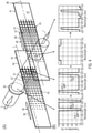
- the spatial pattern 43 allows gradual attenuation of the intensity of fluorescence excitation bands Ex.1, pplX and Ex.2, ICG from 100 % to 0 % by means of the second optical filter 36 as well as the intensity of the white light from 0 to 100 % transmittance by means of the third optical filter 44.
- Filters 36 and 44 are variable filters allowing adjustment of transmittance of the fluorescence excitation bands and the white light intensity, respectively, depending on their position in the path of illumination light 5 along the longitudinal direction L/the axis of movement 40. This is achieved by the spatial pattern 43 of coating 42, 46 which is identical in the shown example for both, the second optical filter 36 and the third optical filter 44.
- the spatial pattern 43 has coverage of 100 % of a first illumination path 47.
- Coverage means the ratio of coated areas with respect to the total area of an illumination path which corresponds to the area of light passing through the respective filters 44, 36 of the illumination filter system 2.
- the spatial pattern 43 has coverage of less than 100 % of a second illumination path 48 on the substrate 41, 45.
- the coating coverage is 0 % in the exemplary second illumination path 48 meaning that no coating 46 at all is applied to the substrate 41, 45 on the position corresponding to the second illumination path 48, which is thus identical to the second operation position 38, in which the filter is out of optical communication.
- a plurality of illumination paths are provided from which as an example, two further illumination paths 49 and 50 are shown in Fig. 5B and 5C .
- the plurality of illumination paths 48, 49, 50, 47 are arranged along the axis of movement 40 on the substrate 41, 45.
- the spatial pattern 43 comprises a plurality of coating patches 51.
- the coating patches 51 are coating squares 52.
- the center 53 of adjacent patches 51/squares 52 are spaced apart equidistantly, i.e. at the same distance d from one another.
- the area A of the patches 51 varies along the axis of movement 40.
- the length I of the patches 51 corresponds to the diagonal length I of the coating squares 52 that varies along the axis of movement 40. In detail, i.e.
- the diagonal of the coating squares 52 increases gradually from an area adjacent to the second illumination path 48 having no coating in direction along the axis of movement 40 to the first illumination path 47 having complete, i.e. 100 % coating.
- the spatial pattern 43 starts from 100 % spatial coverage in the first illumination path 47 shown on the left in Fig. 5 , and the coverage drops gradually along the axis of movement 40 until it is completely absent in the second illumination path 48 on the opposite side, the right side shown in Fig. 5 .
- the coverage i.e. the ratio of coated versus total area of an illumination path determines the percentage of transmittance of the fluorescence excitation bands in case of a second band-stop filter 36 as well as the transmittance and thus intensity of the white light having a wavelength of about 400 ⁇ 750 nm in the shown example by the band-pass filter 44. This can be seen for the four exemplary illumination path 47 to 50 in Figs. 5A and 5D .
- the intensities of the fluorescence excitation bands as well as the white light potion in the spectrally-modified illumination light 7 can thus be individually adjusted.
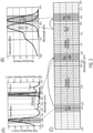
- the combination of all three filters results in a spectrum of the spectrally-modified illumination light 7 with the desired ratio between white light and excitation intensities as it is shown for one example in Fig. 4B.
- Fig 4B shows, from left to right, the quenching of the fluorescence emission bands by the dual-notch filter 35, the attenuation of the white light portion by the band-pass filter 44, the attenuation of the fluorescence excitation light by the second band-stop filter 36. All three of these filters are in optic communication and result in the spectrally-modified illumination light 7 shown on the right side of Fig. 4B .
- the distance d between the centers 53 of the coating patches 51/coating squares 52 should be significantly shorter than the diameter 54 of an illumination path. This way, filtering becomes more homogeneous. Significantly shorter in this respect means a magnitude of at least 10.
- Fig. 6B shows a schematic design of the observation system 3
- Fig. 6A shows the spectral characteristic (transmittance and reflection) of the components of the observation system 3.
- the observation system 3 comprises a beam splitter 21 adapted to split the light image 13 of the illuminated object 6 into a first light portion 16, 17 along a first light path 18 and into a second light portion 20 along a second light path 19.
- the first light portion 16, 17 comprises the fluorescence emission bands Em.1 of pplX and Em.2 of ICG.
- the second portion 20 comprises reflected visible light.
- the beam splitter 21 is a polychroic mirror 55 that reflects light having a wavelength in the fluorescence emission bands Em.1 and Em.2 and transmits all light of the visible spectrum, except for the fluorescence emission band Em.1 falling into the white light spectrum.
- the observation system 3 furthermore comprises the two filters 22 and 24 as well as the two senses 23 and 25 already explained with respect to Fig. 1 above.
- filter 22, through which the first light portion 16, 17 passes before reaching the sensor 23 may be a band-pass filter adapted to transmit light of fluorescence emission bands Em.1 and Em.2 only.
- the filter 24, through which the second light portion 20 passes before reaching a sensor 25 may be a band-stop filter adapted to quench light of fluorescence emission bands Em.1, Em.2 as well as the fluorescence excitation bands Ex.1, Ex.2.
Abstract
Description
- The invention relates to an observation system for medical imaging, in particular multispectral fluorescence imaging, as performed e. g. in a microscope or endoscope, such as a surgical microscope, in particular a surgical multispectral fluorescence microscope, comprising a beam splitter adapted to split a light image, such as an image received from an illuminated object, into a first light portion along a first light path and a second light portion along a second light path.
- The present application further describes an illumination filter system for medical imaging, in particular multispectral fluorescence imaging, as performed e.g. in a microscope or an endoscope, such as a surgical microscope, in particular a surgical multispectral fluorescence microscope, comprising a first optical filter.
- Furthermore, the invention relates to a medical imaging apparatus, such as a microscope or endoscope, or a surgical microscope, in particular a surgical multispectral fluorescence microscope, comprising a light source and an observation system. The medical imaging apparatus optionally further comprises an illumination filter system. The application also describes a medical imaging method, such as a microscopying method or endoscopying method for illuminating and observing an object, the method comprising illuminating the object with illumination light, wherein a light image received from the illuminated object is split into a first light portion along a first light path and a second light portion along a second light path.
- Microscope systems for imaging a color image of reflected visible light and a fluorescence image from an object simultaneously are known from e.g. De Grand and Frangioni, "Operational near-infrared fluorescence imaging system prototype for large animal surgery", Technology in Cancer Research & Treatment, , or from Sato et al. "Development of a new high-resolution intraoperative imaging system (dual-image videoangiography, DIVA) to simultaneously visualize light and near-infrared fluorescence images of indocyanine green angiography", Acta Neurochirurgica (2015), Volume 157, pp 1295-1301. These systems require two light sources, an illumination filter system for each light source as well as an observation system for capturing the image of visible reflected light as well as fluorescence light emitted from the object. Using two light sources is equipment intensive, costly and requires bulky instrumentation. Further, these systems show inhomogeneities in illumination due to the two light sources used, and only one fluorophore can be used at a time with these systems.
- It is therefore the object of the present invention to improve the known observation systems for medical imaging, in particular multispectral fluorescence imaging, as performed e.g. in for a microscope or endoscope, such as a surgical microscope, in particular a surgical multispectral fluorescence microscope, so these systems work with one light source only, are capable of capturing simultaneously at least one fluorescence signal and a signal of reflected visible light and allow a homogeneous illumination for obtaining different images from the object illuminated.
- This object is achieved for the observation system mentioned in the beginning, this object by a system comprising a beam splitter is adapted to split a light image into a first light portion along the first light path and a second light portion comprising reflected visible light along the second light path, wherein the first light portion comprises at least two fluorescence emission bands, wherein the first emission band is in in the visible spectrum, and wherein the second light portion comprises reflected visible light; a first sensor for capturing the at least two fluorescence emission bands of the first light portion; and a second sensor for capturing the visible reflected light of the second light portion.
- The medical imaging apparatus as initially mentioned solves the problem by comprising: a light source for emitting illumination light along an illumination light path onto an object, and an observation system comprising a beam splitter adapted to split a light image, which is sent from the object to the observation system, into a first light portion along a first light path and a second light portion along a second light path, wherein the first light portion comprises at least two fluorescence emission bands, wherein the first fluorescence emission band is in the visible spectrum, and wherein the second light portion comprises visible reflected light.
- Preferred embodiments of the observation filter system and the medical imaging apparatus are defined in the dependent claims.
- For the illumination filter system as initially mentioned, the problem is solved in that the first optical filter is adapted to quench light of at least one fluorescence emission band within the visible spectrum.
- For the imaging method initially mentioned, this problem is solved by splitting the light received from the illuminated object into a first light portion comprising at least one fluorescence emission band in the visible spectrum along the first light path and a second light portion comprising reflected visible light along the second light path.
- The illumination filter system as described herein may simultaneously capture at least one florescence signal and a signal of reflected light with one light source only because the first optical filter merely quenches a fluorescence emission band within the visible spectrum. In the sense of the present application, the visible spectrum is light with a wavelength of 390 to 780nm. This way, only the wavelength corresponding to the fluorescence signal, namely the fluorescence emission band is removed, while light of other wavelength, e.g. visible light and fluorescence excitation light may pass the first optical filter. This allows to simultaneously capture a fluorescence signal and a visible signal from the object illuminated by the illumination system.
- The inventive observation system allows to simultaneously capture visible reflected images of the object as well as at least one fluorescence signal from the object observed because of the specific beam splitter encompassed. This allows for a more time-efficient observation as different fluorescent signals need not be captured one after another. The same applies to the imaging method of the present invention.
- The solutions according to the invention can be improved by the following advantageous features, which are independent of one another and can be combined independently. Further, all features described with respect to the inventive apparatus can be used and accordingly applied in the microscopying method disclosed herein.
- The medical imaging apparatus may comprise the observation filter system as described herein. The medical imaging apparatus may further comprise the illumination filter system as described herein. The medical imaging apparatus may be a microscope or endoscope. The medical imaging apparatus may be a surgical multispectral fluorescence microscope.
- The medical imaging apparatus may comprise an illumination filter system as initially mentioned, wherein the first optical filter is adapted to quench light of the fluorescence emission band, wherein the first optical filter is arranged in optical communication with the light source. The first optical filter may be a band-stop filter. The medical imaging apparatus may contain a single light source only.
- For example, the illumination filter system may be adapted for multispectral imaging, in particular multispectral fluorescence imaging. The illumination filter system may be adapted for a multispectral fluorescence microscope. Such multispectral fluorescence microscope acquires simultaneously at least two, preferably three or more images, such as for example two or more fluorescence signals, or a visible reflectance image as well as at least two fluorescence signals. The preceding list is not exhaustive and the illumination filter system can be easily adapted to the required multispectral image to be acquired.
- According to an aspect of the illumination filter system, the first optical filter may be adapted to quench light with a wavelength of 500-560nm and/or light with a wavelength of 620-650nm. Light with a wavelength of 500-560nm corresponds to the emission spectrum (or band) of fluorescein. Light with wavelengths of 620-650nm corresponds to the emission spectrum of the fluorophore 5-amino levolinic acid-induced protoporphyrin IX (S-ALA/ppIX).
- At least two fluorescence signals can be captured simultaneously, together with a signal of visible reflected light, if the first optical filter is adapted to quench light of at least two fluorescence emission bands within the visible spectrum. The first optical filter may be adapted to quench light within a wavelength of 500-560nm and light with a wavelength of 620-650nm. With such filter, a fluorescein signal as well as a 5-ALA/ppIX signal may be simultaneously captured with an image of visible reflected light using one light source only.
- In another aspect, the illumination filter system may further comprises a second optical filter adapted to attenuate light of a fluorescence excitation band. The second optical filter may be adapted to attenuate light with a wavelength of 390-420nm and/or light with a wavelength of 750-800nm. Using a second filter adapted to attenuate light with a wavelength of 390-420nm, the intensity of light in the excitation band of fluorescene and 5-ALA/ppIX may be reduced. When the second optical filter is adapted to attenuate light with a wavelength of 750-800nm, the intensity of light in the excitation band of indocyanine green (ICG) may be reduced. The second optical filter may be used to avoid unnecessary damaging of the observed object, which may be important when using the illumination filter system in a surgical microscope for observing tissue that is sensitive to light in the range of fluorescence excitation bands. To avoid damaging the tissue, the second optical filter may be used, together with or instead of the first optical filter, e.g. in case of capturing a visible image only.
- In another aspect, the second optical filter may be configured to be moved from a first operation position, in which the second optical filter is in optical communication with the first optical filter, to a second operation position, in which the second optical filter is out of optical communication with the first optical filter. The first optical filter and the second optical filter, if in its first operation position, are in optical communication, which means that illumination light directed onto and passing through the first optical filter subsequently meets and passes the second optical filter in its first operation position. In other words, the expression "optical communication" means that the respective elements are arranged along the same light path.
- Alternatives for directing a light beam through the optical filters of the illumination filter system may be applicable. It is possible to configure each of the first optical filter and the second optical filter to be moveable from the first operation position, in which the optical filter is in optical communication with a light source, to a second operation position in which the optical filter is out of optical communication with the light source, wherein the first optical filter is in its first operation position when the second optical filter is in its second operation position and vice versa. It is also possible to use an illumination filter system, wherein the first optical filter and the second optical filter are arranged out of optical communication with each other and wherein the light source of the microscope is configured to be moved from a first operation position, in which the light source is in optical communication with the first optical filter to a second operation position, in which the light source is in optical communication with the second optical filter.
- In another example, the first optical filter may be band-stop filter that may quench all fluorescence emission bands. For example, if three fluorescent signals are to be captured, the first optical filter may be a triple-band-stop filter quenching the corresponding three fluorescence emission bands. It is also possible to use multiple single-band-stop filters arranged in series, i.e. in optical communication one after another.
- The second optical filter may be a band-stop filter that may attenuate all fluorescence excitation bands. In the example of acquiring three fluorescence signals simultaneously, the second band-stop filter could be a triple-band-stop filter attenuating light of all three fluorescence excitation bands. Likewise, a system with three single-band-stop filters in series may be used as second band-stop filter.
- According to the present application, quenching light means that essentially all light of the respective wavelength is eliminated. Attenuating light in the sense of the present application means that light of the respective wavelength is diminished. Quenching is a specific embodiment of attenuating all light of the respective wavelength.
- The expression "out of optical communication with the first band-stop filter" means that the second optical filter, in its second operation position, may be either arranged completely out of the illumination path, or that the second band-stop filter comprises an illumination path area, which transmits essentially light of all wavelengths.
- The first optical filter may be a band-stop filter adapted to transmit the fluorescence excitation bands and visible light, except for the quench fluorescence emission bands falling into the spectrum of visible light.
- In one exemplary aspect, the first optical filter may be a notch filter, for example a dual-notch filter in case two fluorescence signals are to be captured simultaneously, or a triple-notch filter in case three fluorescence images are to be captured simultaneously, and so on. Likewise, more than one notch filter element may be arranged in a series as the first optical filter in order to eliminate light of any fluorescence emission band to be captured.
- The second optical filter may also be a band-stop filter. It may be adapted to transmit all wavelengths of visible light except the attenuated fluorescence excitation bands in the visible spectrum.
- In a further aspect, the illumination filter system may comprise a third optical filter adapted to transmit light of a fluorescence excitation band only. The third optical filter may transmit light having the wavelength of all fluorescence excitation bands necessary to excite the respective fluorophore in the object to be observed only.
- The third optical filter may be a band-pass filter. The third optical filter may be configured to be moved from a first operation position, in which the third optical filter is in optical communication with the first optical filter (and preferably also with the second optical filter in its first operational position), to a second operation position, in which the third optical filter is out of optical communication with the first optical filter.
- Attenuating the fluorescence excitation bands by the second optical filter allows adjustment of the intensity of fluorescence excitation and may be used to quench the fluorescence excitation in case the illumination filter system is to be used without a fluorescence mode thus avoiding unnecessary exposure of tissue to excitation light.
- The second optical filter may be adapted to adjust the degree of attenuation of the fluorescence excitation bands. Adjusting the degree of attenuation allows an adjustment of the intensity of the excitation light relative to the intensity of white (or visible) light providing a homogenous illumination of the object and improving the quality of the signals/image captured in a microscope using the illumination filter system of this application. The illumination filter system may comprise a control system that is adapted to adjust the degree of attenuation. For example, the second optical filter may comprise a series of filter elements or filter zones having different degrees of attenuation, i.e. attenuating light of the fluorescence excitation band to different degrees. Such a system could, for example comprise three different filters, one completely quenching the light of the fluorescence excitation bands, another one having transmittance of 50-75 % of the fluorescence excitation bands and a third filter having transmittance of about 25-50 % of the fluorescence excitation bands. The control system may be configured to move the respective filter into optical communication with the first optical filter in order to achieve the intended degree of attenuation. In a further aspect, the second optical filter may be a variable filter comprising a plurality of attenuation elements or attenuation areas, each having a different transmittance for the fluorescence excitation bands and thus allowing to vary the degree of attenuation.
- In a further aspect, the second optical filter may comprise a spatial band-stop filter pattern, said spatial pattern having coverage of 100% of a first illumination path on the second optical filter and having coverage of less than 100% of a second illumination path on the second optical filter. The band-stop filter pattern may be a band-stop filter coating applied as a spatial pattern on a substrate. "Coverage" is that portion or fraction of an illumination path with filters the light passing through the illumination path. E.g. coverage of 80% means that 80% of the light passing the illumination pass is filtered, while the other 20% of light passes unfiltered. The coverage may be achieved, e.g. by embedding a certain amount of filtering compound in or by coating a certain amount of filtering material on the filter in the respective illumination path.
- The third optical filter may comprise a spatial band-pass filter pattern, said spatial pattern having coverage of 100% of the first illumination path on/through the third optical filter and having coverage of less than 100% of the second illumination path on the third optical filter. The band-pass filter pattern may be a band-pass filter coating applied as a spatial pattern on a substrate.
- The expression "illumination path" defines a specific area the illumination light path covers on the filter. If the filter is displaced with respect to a light source, the illumination path on the filter likewise changes. In this respect, it is to be noted that different illumination paths on the filter may partially overlap. Thus, a plurality of different illumination paths may be provided on a single filter.
- The filter, or substrate in case of a filter with a patterned coating on a substrate, may essentially transmit all illumination light. E. g. the substrate may be a glass substrate. The ratio of coated versus uncoated areas within a specific illumination path determines the percentage of attenuation for said illumination path. The coverage is the ratio of coated area with respect to the total area of an illumination path.
- The band-stop filter coating may attenuate always 100% of the respective fluorescence excitation band(s). Thus, the percentage of coating within a specific illumination path determines the degree of attenuation of fluorescence excitation bands in said illumination path.
- The band-pass filter coating may always have 100 % transmittance for the respective fluorescence excitation bands, while quenching, i.e. eliminating essentially all other wavelengths. Thus, the coverage determines the degree of attenuation of light having a wavelength outside the fluorescence excitation wavelength. Because of this, for example the degree of attenuation of the intensity of white light may be adjusted. The intensity adjustment allows to use an illumination system in a microscope having one light source only, such as for example a light source emitting illumination light having a wavelength of e.g. 300-900 nm, preferably of 380-800 nm.
- A spatial filter pattern such as for example a filter coating applied in a spatial pattern on a substrate, may likewise allow to adjust the intensity of different fluorescence excitation bands with respect to each other. For example, a substrate may be completely coated with a first coating being a dual band-pass filter coating for a first and a second fluorescence excitation band. The substrate may further be coated in a spatial pattern with a single band-pass filter coating material having 100 % transmittance for the second fluorescence excitation band only, said spatial pattern being as described above and below. This way, the relative intensities of the light in the first fluorescence excitation band may be adjusted relative to the intensity of the light in the second fluorescence excitation band.
- According to a further aspect, the spatial pattern may extend over a plurality of illumination paths provided on the substrate and the coverage, i.e. the ratio coated to the total area of the illumination paths, is different in each illumination path. The coverage may either change stepwise or gradually from one illumination path to another.
- The plurality of illumination paths may be arranged along an axis of movement on the substrate, along which the respective filter is configured to be moved from its first operation position to its second operation position. For example, the substrate may be a slide, i.e. a glass plate having a substantially rectangular, preferably elongated shape. This slide may be moved along a linear axis of movement along the longitudinal axis of the slide. In another example, the substrate may be disc-shaped, which disc may have a rotational axis of movement. The disc may be rotated about its center in order to shift from the first into the second operation position. Other examples are likewise possible. For example, the substrate may have a rectangular shape with different, distinct illumination paths that do not overlap and which may be individually placed in the illumination light path when displacing the substrate accordingly.
- In one example, the spatial pattern may comprise a plurality of coating patches, i.e. spots in which the substrates are coated. The center of adjacent patches is preferably spaced essentially equidistant from each other. In order to achieve a different coverage, i.e. a different ratio of coating in a specific illumination path, the area of patches may vary on the substrate. The center of the patch may be the geometrical center, e. g. the center of the circle where the diameters cross each other or the center of a different shape, such as a square, rectangle, rhombus, or parallelogram, where the diagonals intersect. The area of a patch is the surface of the substrate covered by said patch.
- In one example, the coating patches may be coating squares. The diagonal length of the squares may vary, preferably along the axis of movement of the substrate. This way, it is possible to obtain a spatial pattern having a gradually dropping coverage along the axis of movement.
- For example, in case of the substrate being a slide, a constant number of coating patches/coating squares may be applied in both, the longitudinal as well as the width direction of the slide. In the longitudinal and the width direction, the distance between the adjacent centers of the squares may be the same. In the width direction, all adjacent squares may have the same diagonal length, hence the same area. In the longitudinal direction, the diagonal length and thus the area of the squares may successively increase.
- The distance between the centers of patches as well as the length of the patches/squares are preferably significantly smaller than the area of the illumination paths. Significantly smaller means that the distance/length of patches is smaller by an order of 10.
- The illumination filter system of the present application allows to adjust the intensities of different wavelengths of illumination light such as the intensities of fluorescence excitation bands and the white (or visible) light intensity. The present invention allows to adjust these intensities individually, i.e. adjust the intensity of white light with respect to a first fluorescence excitation band or allows to adjust the intensity of the white light and the first fluorescence excitation band with respect to the second fluorescence excitation band. This improves to simultaneously capture the image of visible light reflected from the object as well as the signals of the fluorescence emission bands.
- In the observation system, the first light portion comprises at least two fluorescence emission bands. The present invention thus allows to simultaneously capture a color image of visible reflected light from the object as well as two fluorescence bands, at least one is, but also both of which may be out of the visible spectrum, by applying the observation system of the present invention.
- The first light portion may comprise light in the wavelength range of 500-560nm (fluorescein emission band) and/or light in the wavelength range of 620-650nm (5-ALA/ppIX emission band). The beam splitter of the observation system may be a polychroic mirror reflecting essentially all of the fluorescence emission bands to be captured and having substantially 100% transmittance of all visible light.
- In a further embodiment, the observation system may further comprise, in the first light path, a band-pass filter adapted to transmit light of the fluorescence emission bands only, which allows to focus and improves the fluorescence emission signals detected by e. g. a sensor arranged in optical communication in the first light path with the band-pass filter.
- The observation system may further comprise, in the second light path, a band-stop filter adapted to quench light of the fluorescence emission band. The band-stop filter may preferably be adapted to quench light of the fluorescence excitation bands as well. This improves the signal of visible reflected light detected by e. g. a sensor arranged, in optical communication with the band-stop filter, such as for example a color camera like CCD device.
- In the following, the invention is described in greater detail in exemplary embodiments with reference to the accompanying figures. The various features in the embodiments may be freely combined as is explained above. If, for a particular application, the advantage which is realized by a particular feature is not needed, this feature can be omitted.
- In the drawings, the same reference numeral is used for elements which correspond to each other with respect to their design and/or their function.
In the drawings: - Fig. 1
- shows a schematic block diagram of a medical imaging apparatus according to an embodiment of the invention;
- Fig. 2A
- shows the excitation and emission bands and spectra of 5-ALA/ppIX;
- Fig. 2B
- shows the excitation and emission spectral and bands of Indocyanine Green (ICG);
- Fig. 2C
- shows how the spectral portions of the light used in an exemplary embodiment of the present invention is distributed over a spectrum of visible and near infrared (NIR) light;
- Fig. 3A
- shows the spectral characteristics (transmittance) of the filters used in an illumination filter system according to a first example;
- Fig. 3B
- shows an illumination system of a first example comprising the filters having the spectral characteristics of
Fig. 3A ; - Fig. 4A
- shows an illumination filter system according to a second example;
- Fig. 4B
- shows the spectral characteristics of the individual filters encompassed by the illumination filter system as shown in
Fig. 4A as well as the spectra characteristics of the whole illumination filter system; - Fig. 5A
- shows the spectral characteristics of the optical filter of
Fig. 5B in the respective illumination path; - Fig. 5B
- shows a first variable optical filter having a spatial pattern coating;
- Fig. 5C
- shows a second variable optical filter having a spatial pattern coating;
- Fig. 5D
- shows the spectral characteristics of the optical filter of
Fig. 5C in the respective illumination path; - Fig. 6A
- shows the spectral characteristics (transmittance and reflectance) of filters and the beam splitter of an observation system according to an embodiment of the invention; and
- Fig. 6B
- shows an observation system according to an embodiment comprising filters and a beam splitter having the spectra characteristics shown in
Fig. 6A . - First, the design and function of a medical imaging apparatus, such as a
microscope 1 or endoscope comprising an exemplaryillumination filter system 2 as well as anexemplary observation system 3 is explained with reference toFig. 1 . Themicroscope 1 comprises alight source 4 that emits anillumination light 5 onto an object 6 to be observed applying a microscopying method according to the present application. Theillumination filter system 2 is in optical communication with thelight source 4 as well as the object 6, that is, theillumination system 2 is in the light path of theillumination light 5 from the light source to the object 6. - The
illumination filter system 2 filters and spectrally modifies theillumination light 5. It adjusts the intensity of specific portions within theillumination light 5 relative to each other, as will be explained in more detail below with respect to an example of theillumination filter system 2 that may be part of the present invention. Thus, spectrally modified illumination light 7 exits theillumination filter system 2 and is directed onto the object 6. The spectrally modified illumination light 7 is specifically adapted in order to improve a multi-spectral fluorescence microscopying method. In the shown example, the spectrally modified illumination light 7, provided by theillumination filter system 2, is adapted in order to capture a reflected visible image as well as two fluorescence signals simultaneously, which will also be described in more detail below. - The
light source 4 as well as theillumination filter system 2 are both regulated by acontroller 8. Thecontroller 8 is connected with thelight source 4 via abi-directional signal line 9, via which thecontroller 8 may regulate, for example, the intensity of theillumination light 5 or, in case of a light unit having two different light sources, selects the respective light source for emitting theillumination light 5. Via anotherbi-directional signal line 10, thecontroller 8 also regulates theillumination filter system 2, e.g. by setting the filters for adjusting the degree of attenuation of certain filters in order to adjust the ratio of light intensities of certain spectral bands included in the spectrally modified illumination light 7. Usingbi-directional signal lines light source 4 and thefilter system 2. - The
controller 8 itself is coupled via a furtherbi-directional signal line 11 with acontroller interface 12 for inputting settings of the microscope. - A
light image 13 is sent from the object 6 to theobservation system 3 at definedmicroscope settings 14. InFigure 1 , themicroscope observation settings 14, such as the working distance, magnification, elements used theobservation system 3 are represented as a box. Thecontroller 8 may adjust the observation parameters of the microscope via afurther signal line 15. Thelight image 13 sent from object 6 toobservation system 3, is split into afirst light portion first light path 18 and the secondlight portion 20 along a secondlight path 19 in abeam splitter 21 of theobservation system 3. Thefirst light portion first light portion pass filter 22. The first emission band and the second fluorescence emission band of the first light portion 16', 17' exiting the band-pass filter 22 are captured by thefluorescence sensor 23. Thefluorescence sensor 23 may for example be a fluorescence camera, for example, an NIR camera if the fluorescent emission bands are in the near infrared range. - The second
light portion 20 passes through the band-stop filter 24. The reflected visible light of the second light portion 20' exiting the band-stop filter 24 is captured by asecond sensor 25. Thesecond sensor 25 may be a visible camera such as for example a charge coupled device (CCD). - The
first sensor 23, sends, via a signal line 26 a first image read-out I1 comprising information on the captured fluorescence emission bands to aprocessing unit 28. A second image readout I2 is sent via asignal line 27 from asecond sensor 25 to theprocessing unit 28. The image readout I2 contains the image data of the reflected visible light 20' captured by thesensor 25. - The
processing unit 28 is further connected to each of thesensor 23 and thesensor 25 by abi-directional signal lines bi-directional signal lines processing unit 28 controls thesensors sensors sensors processing unit 28. Theprocessing unit 28 itself may receive the settings from a user of the microscope by inputting the corresponding parameters into thecontroller interface 12 and sending the settings via asignal line 31. - The
processing unit 28 may process the image readouts I1 and I2. Preferably, a pseudo-image P may be generated by theprocessing unit 28 and sent from theprocessing unit 28 viasignal line 32 to adisplay device 33, such as for example, a monitor. Even though it is not shown inFigure 1 , the pseudo-image P may be stored in a documentation system. The pseudo-image P may be a merger of the image readout I1 from the fluorescence (FL)sensor 23 and the VISR image readout I2 from thevisible camera 25. It is to be noted that the merged pseudo-image P is not merely an overlay of the image readouts I1 and I2. The pseudo-image P does not obscure any image readout information (which would be the case by overlaying the two image readouts I1 and I2), but rather presents the fluorescence image readout within the VISR image readout I2 in a natural way, resembling the injection of a bright dye. The pseudo-image P may be generated in real time allowing the user of themicroscope 1 to capture a combination of the white light image and fluorescence light signals in one merged image. - In order to improve the quality of the pseudo-image P, the image readouts I1 and I2 may be homogenized. The homogenization may correct inhomogeneities in illumination and vignetting of the image optics which would otherwise result in an uneven brightness across the field of view as the periphery of the field of view may be significantly darker at the periphery than in the center. Further, the homogenized image readouts I1 and I2 may be aligned with each other before merging. For example, a spatial correction transformation may be performed to correct alignment errors in the relative position of the two
sensors sensors fluorescence sensor 23 in order to remove a dark current from thefluorescence sensor 23, thus avoiding a false contribution in measurement of the fluorescence signals. - The
controller 8 may provide theprocessing unit 28, via asignal line 34, with data of themicroscope settings 14 that may be inputted by the user via thecontroller interface 12, such as for example, the working distance, magnification, as well as settings of theillumination filter system 2, thelight source 1. -
Figures 2A to 2C illustrate the excitation and emission spectra of the fluorophores 5-amino levolinic acid-induced protoporphyrin IX (5-ALA/ppIX) (Fig. 2A ) and indocyanine green (ICG) (Fig. 2B ). Ex.1, pplX indicates the excitation band of 5-ALA/ppIX, Em.1, pplX indicates the fluorescence emission band of protoporphyrin IX, Ex.2, ICG indicates the fluorescent excitation band of ICG, and Em.2, ICG indicates the fluorescence emission band of ICG. - The graph of
Fig. 2C shows the fluorescence excitation and emission bands as well as the visible spectrum, in particular the visible reflected (VISR) light over the wavelengths. As will be explained in more detail below, the VISR spectrum defined inFigure 2C is directed onto thesecond sensor 25, the VISR-sensor. The fluorescence emission bands Em.1, pplX and Em.2, ICG are directed to thesensor 23, i.e. the fluorescence sensor. Thus, the spectrum of the visible reflected light indicated inFig. 2C corresponds to the second light portion 20' inFig. 1 . The two fluorescence emission spectra Em.1, pplX and Em.2, ICG indicated inFig. 2C correspond to the first light portions 16' and 17', respectively. - In order to clearly distinguish the spectral bands, in particular, exclude the fluorescence excitation band of photoporphyrin IX and avoid an overlapping of the fluorescence excitation bands with the visible spectrum, in particular the visible reflected light, the
illumination filter system 2 and theobservation system 3 of the present invention are used, as will be explained in the following. - First, the design and function of an exemplary
illumination filter system 2 according to a first example is explained with reference toFigs. 3A and 3B. Figure 3B shows an example of anillumination filter system 2 in optical communication with alight source 4. Theillumination filter system 2 is arranged in the light path of theillumination light 5. Theillumination filter system 2 comprises a firstoptical filter 35. The firstoptical filter 35 may be a band-stop filter. The firstoptical filter 35 is adapted to quench light of the fluorescence emission bands within the visible spectrum. In the shown example, the fluorescence emission bands Em.1 and Em.2 for pplX and ICG are quenched, respectively. The firstoptical filter 35 is always in optical communication with thelight source 4, thus, the fluorescence emission bands to be detected bysensors 23 are always eliminated from theillumination light 5 by theillumination filter system 2. - The
illumination filter system 2 of the shown example furthermore comprises a secondoptical filter 36. The secondoptical filter 36, which is optional, may be a band-stop filter. The secondoptical filter 36 is configured to be moved from afirst operation position 37, indicated in dashed lines inFig. 3B . In thefirst operation position 37, the secondoptical filter 36 is in optical communication with the firstoptical filter 35, that is, theillumination light 5 passes both the firstoptical filter 35 and the secondoptical filter 36 when the latter is in itsfirst operation position 37. - The second
optical filter 36 is configured to be moved from thefirst operation position 37 to asecond operation position 38, in which the secondoptical filter 36 is out of optical communication with the firstoptical filter 35. In asecond operation position 38, the secondoptical filter 36 is not arranged in the light path of theillumination light 5, so theillumination light 5 passes only the firstoptical filter 35 and not the secondoptical filter 36 if the latter is in itssecond operation position 38. - The arrow indicates the
transition 39 of the secondoptical filter 36 from itsfirst operation position 37 to itssecond operation position 38. Thistransition 39 may be performed, e.g. by displacing thefilter 36 into and out of optical communication with the firstoptical filter 35. - As can be seen in
Fig. 3A , the firstoptical filter 35 is a band-stop filter adapted to transmit light of the fluorescence excitation bands Ex. 1 of pplX and Ex. 2, ICG as well as the whole spectrum of visible light and a portion of NIR light adjacent to the visible light, except for the quenched fluorescence emission band Em.1 of pplX. - The first
optical filter 35 may be a dual-notch filter quenching the excitation bands of Em.1 pplX and Em.2 ICG. - The second
optical filter 36 is adapted to transmit the visible reflected light, except for the fluorescence excitation bands Ex.1 and Ex.2 attenuated by said secondoptical filter 36. - This way, the fluorescence excitation bands may be switched on and off.
- The
illumination filter system 2 of the present application allows to adjust the intensity of fluorescence excitation relative to white light and/or the intensity of difference fluorescence excitation bands. Such relative intensity adjustment is useful when for example the maximum excitation power is needed, while maximum white light illumination is too bright for the use of the eyepiece of a microscope. - The
illumination filter system 2 of the present application may also be used to adjust the intensity ratio of the excitation light and the white (or visible) light, for example using anillumination filter system 2 according to a second example. The design and function of theillumination filter system 2 of the second example is explained with reference toFig. 3A and 3B in the following. - The design and function of another exemplary
illumination filter system 2 will be explained with reference toFigs. 4 and5 . Theillumination filter system 2 shown inFigs. 4 and5 comprises the firstoptical filter 35, which may be a dual-notch filter to eliminate any light at the fluorescence emission bands Em.1, pplX and Em.2, ICG. Theillumination filter system 2 shown inFigs. 4 and5 furthermore comprises a secondoptical filter 36 adapted to attenuate light of the fluorescence excitation bands Ex.1, pplX and Ex.2, ICG. The secondoptical filter 36 is configured to be moved from afirst operation position 37, in which it is in optical communication with the firstoptical filter 35, to asecond operation position 38.Transition 39 between thefirst operation position 37 and thesecond operation position 38 is achieved by moving the secondoptical filter 36 along an axis ofmovement 40. - The second
optical filter 36 may comprise a rectangular substrate, in the Figure shown a glass slide, 41 and the axis ofmovement 40 corresponds to the longitudinal direction L of thesubstrate 41. - A band-
stop filter coating 42 is applied in aspatial pattern 43 of thesubstrate 41, whichpattern 43 will be described in more detail below. - The
illumination filter system 2 shown inFigs. 4 and5 furthermore comprises a thirdoptical filter 44 adapted to transmit light of the fluorescence excitation bands Ex.1, pplX and Ex.2, ICG only. The thirdoptical filter 44 may be a band-pass filter 44. Like the secondoptical filter 36, the thirdoptical filter 44 is configured to be moved from afirst operation position 37, in which the thirdoptical filter 44 is in optical communication with the firstoptical filter 35, to asecond operation position 38 in which the thirdoptical filter 44 is out of optical communication with the firstoptical filter 35. - The third
optical filter 44 is likewise comprised in asubstrate 45, similar to thesubstrate 41, which is also composed of a clean glass slide having a rectangular shape, and which can be moved along its longitudinal axis L, which is identical to the axis ofmovement 40, duringtransition 39 from thefirst operation position 37 into thesecond operation position 38. - The
substrate 45 of the thirdoptical filter 44 comprises a band-pass filter coating 46 which is applied in aspatial pattern 43 similar to thespatial pattern 43 of the secondoptical filter 36 on thesubstrate 41. - The
spatial pattern 43 allows gradual attenuation of the intensity of fluorescence excitation bands Ex.1, pplX and Ex.2, ICG from 100 % to 0 % by means of the secondoptical filter 36 as well as the intensity of the white light from 0 to 100 % transmittance by means of the thirdoptical filter 44. -
Filters illumination light 5 along the longitudinal direction L/the axis ofmovement 40. This is achieved by thespatial pattern 43 ofcoating optical filter 36 and the thirdoptical filter 44. - The
spatial pattern 43 has coverage of 100 % of afirst illumination path 47. Coverage means the ratio of coated areas with respect to the total area of an illumination path which corresponds to the area of light passing through therespective filters illumination filter system 2. - The
spatial pattern 43 has coverage of less than 100 % of asecond illumination path 48 on thesubstrate second illumination path 48 meaning that nocoating 46 at all is applied to thesubstrate second illumination path 48, which is thus identical to thesecond operation position 38, in which the filter is out of optical communication. In between thefirst illumination path 47, which is on one end ofsubstrate second illumination path 48, which is on the opposite end along the longitudinal direction L of thesubstrate further illumination paths Fig. 5B and 5C . - The plurality of
illumination paths movement 40 on thesubstrate spatial pattern 43 comprises a plurality ofcoating patches 51. In the shown example, thecoating patches 51 are coatingsquares 52. The center 53 ofadjacent patches 51/squares 52 are spaced apart equidistantly, i.e. at the same distance d from one another. However, the area A of thepatches 51 varies along the axis ofmovement 40. In the shown example, the length I of thepatches 51, corresponds to the diagonal length I of thecoating squares 52 that varies along the axis ofmovement 40. In detail, i.e. the diagonal of thecoating squares 52 increases gradually from an area adjacent to thesecond illumination path 48 having no coating in direction along the axis ofmovement 40 to thefirst illumination path 47 having complete, i.e. 100 % coating. Thespatial pattern 43 starts from 100 % spatial coverage in thefirst illumination path 47 shown on the left inFig. 5 , and the coverage drops gradually along the axis ofmovement 40 until it is completely absent in thesecond illumination path 48 on the opposite side, the right side shown inFig. 5 . - The coverage, i.e. the ratio of coated versus total area of an illumination path determines the percentage of transmittance of the fluorescence excitation bands in case of a second band-
stop filter 36 as well as the transmittance and thus intensity of the white light having a wavelength of about 400 ― 750 nm in the shown example by the band-pass filter 44. This can be seen for the fourexemplary illumination path 47 to 50 inFigs. 5A and 5D . - The intensities of the fluorescence excitation bands as well as the white light potion in the spectrally-modified illumination light 7 can thus be individually adjusted. The combination of all three filters results in a spectrum of the spectrally-modified illumination light 7 with the desired ratio between white light and excitation intensities as it is shown for one example in
Fig. 4B. Fig 4B shows, from left to right, the quenching of the fluorescence emission bands by the dual-notch filter 35, the attenuation of the white light portion by the band-pass filter 44, the attenuation of the fluorescence excitation light by the second band-stop filter 36. All three of these filters are in optic communication and result in the spectrally-modified illumination light 7 shown on the right side ofFig. 4B . - In order to obtain a nearly gradual changing coverage of the
coating coating patches 51/coating squares 52 should be significantly shorter than thediameter 54 of an illumination path. This way, filtering becomes more homogeneous. Significantly shorter in this respect means a magnitude of at least 10. - Finally, an exemplary embodiment of an
observation system 3 is explained with reference toFig. 6. Fig. 6B shows a schematic design of theobservation system 3 andFig. 6A shows the spectral characteristic (transmittance and reflection) of the components of theobservation system 3. - The
observation system 3 comprises abeam splitter 21 adapted to split thelight image 13 of the illuminated object 6 into afirst light portion first light path 18 and into a secondlight portion 20 along a secondlight path 19. Thefirst light portion second portion 20 comprises reflected visible light. In the shown embodiment, thebeam splitter 21 is a polychroic mirror 55 that reflects light having a wavelength in the fluorescence emission bands Em.1 and Em.2 and transmits all light of the visible spectrum, except for the fluorescence emission band Em.1 falling into the white light spectrum. Theobservation system 3 furthermore comprises the twofilters senses Fig. 1 above. Further,filter 22, through which thefirst light portion sensor 23, may be a band-pass filter adapted to transmit light of fluorescence emission bands Em.1 and Em.2 only. Thefilter 24, through which the secondlight portion 20 passes before reaching asensor 25 may be a band-stop filter adapted to quench light of fluorescence emission bands Em.1, Em.2 as well as the fluorescence excitation bands Ex.1, Ex.2. -
Item 1. Illumination filter system (2) for medical imaging, in particular multispectral fluorescence imaging, comprising a first optical filter (35) adapted to quench light of at least one fluorescence emission band (Em.1, Em.2) within the visible spectrum. -
Item 2. Illumination filter system (2) ofitem 1, wherein the first optical filter (35) is adapted to quench light with a wavelength of 500-560nm and/or light with a wavelength of 620-650nm. -
Item 3. Illumination filter system (2) ofitem -
Item 4. Illumination filter system (2) ofitem 3, wherein the second optical filter (36) is adapted to attenuate light with a wavelength of 390-420nm and/or light with a wavelength of 750-800nm. -
Item 5. Illumination filter system (2) of any one ofitems - Item 6. Illumination filter system (2) of any one of
items 1 to 5, wherein the first optical filter (35) is a band-stop filter adapted to transmit the fluorescence excitation bands (Ex.1, Ex.2) and visible light, except for the quenched fluorescence emission bands (Em.1, Em.2) in the visible spectrum. - Item 7. Illumination filter system (2) of any one of
items 3 to 6, wherein the second optical filter (36) is a band-stop filter adapted to transmit all wavelengths of visible light, except the attenuated fluorescence excitation bands (Ex.1, Ex.2). -
Item 8. Ilumination filter system (2) of any one ofitems 3 to 7, wherein the second optical filter (36) comprises a spatial band-stop filter pattern (43), said spatial pattern (43) having coverage of 100 % of a first illumination path (47) on the second optical filter (36) and having coverage of less than 100 % of a second illumination path (48, 49, 50) on the second optical filter (36). -
Item 9. Illumination filter system (2) ofitem 8, wherein the spatial band-stop filter pattern (43) extends over a plurality of illumination paths (47-50) provided on the second optical filter (36) and the coverage is different in each illumination path (47-50). -
Item 10. Observation system (3) for medical imaging, in particular multispectral fluorescence imaging, comprising a beam splitter (21) adapted to split a light image (13) into a first light portion (16, 17) along a first light path (18) and a second light portion (20) along a second light path (19), wherein the first light portion (16, 17) comprises at least one fluorescence emission band (Em.1, Em.2) in the visible spectrum and wherein the second light portion (20) portion comprises visible reflected light. -
Item 11. Observation system (3) ofitem 10, wherein the first light portion (16, 17) comprises at least two fluorescence emission bands (Em.1, Em.2). -
Item 12. Observation system (3) ofitem -
Item 13. Observation system (3) ofitems first light path 18, a band-pass filter (22) adapted to transmit light of the fluorescence emission bands (Em.1, Em.2) only. -
Item 14. Observation system (3) of any one ofitems 11 to 13, further comprising, in the second light path (19), a band-stop filter (24) adapted to quench light of the fluorescence emission bands (Em.1, Em.2), said band-stop filter (24) preferably also being adapted to quench light of the fluorescence excitation bands (Ex.1, Ex.2). -
Item 15. Medical imaging apparatus (1), such as a microscope (1) or endoscope, in particular a surgical multispectral fluorescence microscope, comprising an illumination filter system (2) according to any one ofitems 1 to 10, wherein the first band-stop filter (35) is arranged in optical communication with a light source (4) and/or an observation system (3) according to any one ofitems 11 to 14.
| 1 | Microscope / Medical imaging apparatus |
| 2 | Illumination Filter System |
| 3 | Observation System |
| 4 | Light Source |
| 5 | Illumination Light |
| 6 | Object |
| 7 | Spectrally Modified Illumination Light |
| 8 | Controller |
| 9 | Signal Line |
| 10 | Signal Line |
| 11 | Signal Line |
| 12 | Controller Interface |
| 13 | Light Image |
| 14 | Microscope Settings |
| 15 | Signal Line |
| 16, 16' | 1st Light Portion |
| 17, 17' | 1st Light Portion |
| 18 | 1st Light Path |
| 19 | 2nd Light Path |
| 20 | 2nd Light Portion /VISR |
| 21 | Beam Splitter |
| 22 | Band-Pass Filter |
| 23 | 1st Sensor /FL-Sensor |
| 24 | Band-Stop Filter |
| 25 | 2nd Sensor / VISR-Sensor |
| 26 | Signal Line |
| 27 | Signal Line |
| 28 | Processing Unit |
| 29 | Signal Line |
| 30 | Signal Line |
| 31 | Signal Line |
| 32 | Signal Line |
| 33 | Display Device |
| 34 | Signal Line |
| 35 | 1st Optical (Band-stop) Filter |
| 36 | 2nd Optical (Band-stop) Filter |
| 37 | 1st Operation Position |
| 38 | 2nd Operation Position |
| 39 | Transition |
| 40 | Axis of Movement |
| 41 | Substrate |
| 42 | Band-Stop Filter Coating |
| 43 | Spatial Pattern |
| 44 | 3rd optical (Band-pass) filter |
| 45 | Substrate |
| 46 | Band-Pass Filter Coating |
| 47 | 1st Illumination Path |
| 48 | 2nd Illumination Path |
| 49 | 3rd Illumination Path |
| 50 | 4th Illumination Path |
| 51 | Coating Patch |
| 52 | Coating Square |
| 53 | Center of Coating Patch/Square |
| 54 | Diameter of Illumination Path |
| 55 | Polychroic Mirror |
| A | Area of Coating Patch/Square |
| d | Distance Between Adjacent Centers |
| Ex.1 | Excitation Band of ppIX |
| Em.1 | Emission Band of ppIX |
| Ex.2 | Excitation Band of ICG |
| Em.2 | Emission Band of ICG |
| I1 | Image Readout (FL) |
| I2 | Image Readout (VISR) |
| L | Longitudinal Direction |
| I | Length of Patch/Diagonal of Square |
| P | Pseudo-image |
| VISR | Visible Reflected Light |
Claims (15)
- Observation system (3) for medical imaging, in particular multispectral fluorescence imaging, comprising:a beam splitter (21) adapted to split a light image (13) into a first light portion (16, 17) along a first light path (18) and a second light portion (20) along a second light path (19), wherein the first light portion (16, 17) comprises at least two fluorescence emission bands (Em.1, Em.2), wherein the first fluorescence emission band (Em.1) is in the visible spectrum, and wherein the second light portion (20) comprises visible reflected light;a first sensor (23) for capturing the at least two fluorescence emission bands (Em.1, Em.2) of the first light portion (16, 17); anda second sensor (24) for capturing the visible reflected light of the second light portion (20).
- Observation system (3) of claim 1, wherein the first light portion comprises the fluorescence light of the light image, and the second light portion comprises the visible reflected light of the light image and not the fluorescence light of the light image
- Observation system (3) of claim 1 or 2, wherein the second fluorescence emission band (Em.2) is in the infrared spectrum.
- Observation system (3) of any one of claims 1 to 3, wherein the first light portion (16, 17) comprises light in the wavelength range of 500-560nm and/or light in the wavelength range of 620-650nm.
- Observation system (3) of any one of claims 1 to 4, furthermore comprising, in the first light path 18, a band-pass filter (22) adapted to transmit light of the fluorescence emission bands (Em.1, Em.2) only.
- Observation system (3) of any one of claims 1 to 5, further comprising, in the second light path (19), a band-stop filter (24) adapted to quench light of the fluorescence emission bands (Em.1, Em.2)
- Observation system (3) of claim 6, wherein the band-stop filter (24) is also adapted to quench light of the fluorescence excitation bands (Ex.1, Ex.2).
- Observation system (3) of any one of claims 1 to 7, wherein the beam splitter (21) is a polychroic mirror reflecting essentially all of the light of the fluorescence emission bands and having substantially 100% transmittance of all visible light
- Medical imaging apparatus (1), such as a microscope (1) or endoscope, in particular a surgical multispectral fluorescence microscope, comprising:a light source (4) for emitting illumination light (5) along an illumination light path onto an object (6), andan observation system (3) comprising a beam splitter (21) adapted to split a light image (13), which is sent from the object (6) to the observation system (3), into a first light portion (16, 17) along a first light path (18) and a second light portion (20) along a second light path (19), wherein the first light portion (16, 17) comprises at least two fluorescence emission bands (Em.1, Em.2), wherein the first fluorescence emission band (Em.1) is in the visible spectrum and wherein the second light portion (20) comprises visible reflected light.
- Medical imaging apparatus (1) of claim 9, wherein the observation system (3) is the observation system according to any one of claims 1 to 8.
- Medical imaging apparatus (1) of claim 9 or 10, wherein the beam splitter (21) is outside of the illumination light path.
- Medical imaging apparatus (1) of any one of claims 9 to 11, further comprising an illumination filter system (2) comprising a first optical filter (35) adapted to quench light of the fluorescence emission bands (Em.1, Em.2), wherein the first optical filter (35) is arranged in optical communication with a light source (4).
- Medical imaging apparatus (1) of any one of claims 9 to 12, wherein the second fluorescence emission band (Em2) is in the infrared spectrum.
- Medical imaging apparatus (1) of any one of claims 9 to 12, wherein the medical imaging apparatus (1) is one of an endoscope and a microscope.
- Medical imaging apparatus (1) of claim 14, wherein the medical imaging apparatus (1), is a surgical multispectral fluorescence microscope.
Priority Applications (1)
| Application Number | Priority Date | Filing Date | Title |
|---|---|---|---|
| EP21184184.6A EP3940436A1 (en) | 2016-02-15 | 2016-02-15 | Illumination filter system and observation system for a multispectral fluorescence microscope, multispectral fluorescence microscope, and microscopying method |
Applications Claiming Priority (2)
| Application Number | Priority Date | Filing Date | Title |
|---|---|---|---|
| EP16155623.8A EP3206061A1 (en) | 2016-02-15 | 2016-02-15 | Illumination filter system and observation system for a multispectral fluorescence microscope |
| EP21184184.6A EP3940436A1 (en) | 2016-02-15 | 2016-02-15 | Illumination filter system and observation system for a multispectral fluorescence microscope, multispectral fluorescence microscope, and microscopying method |
Related Parent Applications (1)
| Application Number | Title | Priority Date | Filing Date |
|---|---|---|---|
| EP16155623.8A Division EP3206061A1 (en) | 2016-02-15 | 2016-02-15 | Illumination filter system and observation system for a multispectral fluorescence microscope |
Publications (1)
| Publication Number | Publication Date |
|---|---|
| EP3940436A1 true EP3940436A1 (en) | 2022-01-19 |
Family
ID=55359447
Family Applications (2)
| Application Number | Title | Priority Date | Filing Date |
|---|---|---|---|
| EP16155623.8A Pending EP3206061A1 (en) | 2016-02-15 | 2016-02-15 | Illumination filter system and observation system for a multispectral fluorescence microscope |
| EP21184184.6A Pending EP3940436A1 (en) | 2016-02-15 | 2016-02-15 | Illumination filter system and observation system for a multispectral fluorescence microscope, multispectral fluorescence microscope, and microscopying method |
Family Applications Before (1)
| Application Number | Title | Priority Date | Filing Date |
|---|---|---|---|
| EP16155623.8A Pending EP3206061A1 (en) | 2016-02-15 | 2016-02-15 | Illumination filter system and observation system for a multispectral fluorescence microscope |
Country Status (4)
| Country | Link |
|---|---|
| US (2) | US10823947B2 (en) |
| EP (2) | EP3206061A1 (en) |
| JP (1) | JP6429916B2 (en) |
| CN (2) | CN107080594B (en) |
Families Citing this family (16)
| Publication number | Priority date | Publication date | Assignee | Title |
|---|---|---|---|---|
| SG10202108966SA (en) * | 2017-03-30 | 2021-09-29 | Agency Science Tech & Res | Optical probe, raman spectroscopy system, and method of using the same |
| EP4245210A3 (en) * | 2018-01-05 | 2023-12-13 | Boston Scientific Scimed, Inc. | Fluorophore imaging devices, systems, and methods for an endoscopic procedure |
| EP3514600A1 (en) * | 2018-01-19 | 2019-07-24 | Leica Instruments (Singapore) Pte. Ltd. | Method for fluorescence intensity normalization |
| EP3540494B1 (en) | 2018-03-16 | 2022-11-23 | Leica Instruments (Singapore) Pte. Ltd. | Augmented reality surgical microscope and microscopy method |
| CN108287021B (en) * | 2018-04-02 | 2023-07-07 | 福建师范大学 | Dual-channel hyperspectral microscopic imaging device and method for acquiring spectral information in different stages |
| DE102018111958A1 (en) * | 2018-05-17 | 2019-11-21 | Carl Zeiss Meditec Ag | Filter set, system and method for monitoring protoporphyrin IX |
| EP4239390A3 (en) * | 2018-12-21 | 2023-11-15 | Leica Instruments (Singapore) Pte Ltd | Fluorescence observation device and method for emulating a first type of fluorescence observation device on a second type of fluorescence observation device |
| USD908881S1 (en) | 2019-01-17 | 2021-01-26 | Sbi Alapharma Canada, Inc. | Handheld endoscopic imaging device |
| EP4284131A3 (en) * | 2019-01-17 | 2024-02-14 | SBI Alapharma Canada, Inc. | Modular endoscopic system for visualization of disease |
| DE102019101773B9 (en) | 2019-01-24 | 2021-11-25 | Carl Zeiss Meditec Ag | Microscopy system and method for operating a microscopy system |
| EP3819699B1 (en) * | 2019-11-08 | 2024-02-21 | Leica Instruments (Singapore) Pte. Ltd. | Optical system and corresponding apparatus, method and computer program |
| EP3882681A1 (en) * | 2020-03-10 | 2021-09-22 | Leica Instruments (Singapore) Pte. Ltd. | A concept for a microscope system with an led-based illumination system |
| EP3882682A1 (en) | 2020-03-20 | 2021-09-22 | Leica Instruments (Singapore) Pte. Ltd. | Illumination system, system, method and computer program for a microscope system |
| DE102020132978A1 (en) * | 2020-12-10 | 2022-06-15 | Karl Storz Se & Co. Kg | Capturing images of a medical object in white light and fluorescent light |
| KR102549929B1 (en) * | 2021-08-05 | 2023-06-30 | 주식회사 메타플바이오 | Three-dimensional fluorescence detection apparatus |
| EP4327717A1 (en) | 2022-08-22 | 2024-02-28 | Leica Instruments (Singapore) Pte Ltd | Medical imaging system and method of operating a medical imaging system |
Citations (6)
| Publication number | Priority date | Publication date | Assignee | Title |
|---|---|---|---|---|
| WO1999001749A1 (en) * | 1997-07-03 | 1999-01-14 | Smith & Nephew, Inc. | Fluorescence imaging system |
| US20030078477A1 (en) * | 2001-10-18 | 2003-04-24 | Korea Electrotechnology Research Institute | Fluorescence endoscope apparatus and method for imaging tissue within a body using the same |
| DE102011002990A1 (en) * | 2011-01-21 | 2012-07-26 | Carl Zeiss Meditec Ag | System for visualizing tissue in an operating area |
| US20120300294A1 (en) * | 2010-08-09 | 2012-11-29 | Carl Zeiss Meditec Ag | Fluorescence observation system and set of filters |
| WO2013109966A1 (en) * | 2012-01-20 | 2013-07-25 | The Trustees Of Dartmouth College | Method and apparatus for quantitative hyperspectral fluorescence and reflectance imaging for surgical guidance |
| EP2728344A1 (en) * | 2011-06-29 | 2014-05-07 | Kyoto Prefectural Public University Corporation | Tumor site identification device and method |
Family Cites Families (25)
| Publication number | Priority date | Publication date | Assignee | Title |
|---|---|---|---|---|
| DE3116858A1 (en) | 1980-05-02 | 1982-01-28 | CIBA-GEIGY AG, 4002 Basel | LIGHTING SYSTEM FOR THE PRODUCTION OF PRINTS ON LIGHT-SENSITIVE MATERIAL WITH VARIABLE CONTRAST, USED FILTER STRIPES, AND THE LAMP HOUSE CONTAINING THEM |
| GB2075698B (en) * | 1980-05-02 | 1984-03-07 | Ciba Geigy Ag | Light filter |
| US6198532B1 (en) * | 1991-02-22 | 2001-03-06 | Applied Spectral Imaging Ltd. | Spectral bio-imaging of the eye |
| JP3526489B2 (en) * | 1995-05-25 | 2004-05-17 | オリンパス株式会社 | Epi-fluorescence microscope |
| US5953477A (en) * | 1995-11-20 | 1999-09-14 | Visionex, Inc. | Method and apparatus for improved fiber optic light management |
| DE10132360C1 (en) * | 2001-07-04 | 2002-11-28 | Leica Microsystems | Color-neutral brightness adjustment for microscope illumination beam path has filter for compensating red shift in light source spectrum adjusted in dependence on brightness of light source |
| US9468750B2 (en) * | 2006-11-09 | 2016-10-18 | Greatbatch Ltd. | Multilayer planar spiral inductor filter for medical therapeutic or diagnostic applications |
| US9827415B2 (en) * | 2006-11-09 | 2017-11-28 | Greatbatch Ltd. | Implantable lead having multi-planar spiral inductor filter |
| JP5174370B2 (en) * | 2007-04-13 | 2013-04-03 | Hoya株式会社 | Fluorescence endoscope system and light source unit |
| DE102009024943A1 (en) * | 2009-06-10 | 2010-12-16 | W.O.M. World Of Medicine Ag | Imaging system and method for fluorescence-optical visualization of an object |
| DE102011016138A1 (en) * | 2011-03-30 | 2012-10-04 | Karl Storz Gmbh & Co. Kg | Device for fluorescence diagnosis |
| JP5898322B2 (en) * | 2011-10-12 | 2016-04-06 | ベンタナ メディカル システムズ, インコーポレイテッド | Multifocal interferometer image acquisition |
| JP6042073B2 (en) * | 2012-01-30 | 2016-12-14 | 黎明 李 | Laparoscopic diagnostic equipment |
| EP2876482A4 (en) * | 2012-07-19 | 2016-04-13 | Nikon Corp | Optical element, optical device, measurement device, and screening device |
| JPWO2014030344A1 (en) * | 2012-08-23 | 2016-07-28 | Sbiファーマ株式会社 | Photodynamic diagnostic device with collimator |
| WO2014124015A1 (en) * | 2013-02-05 | 2014-08-14 | Vanderbilt University | Microlens array for enhanced imaging of multiregion targets |
| KR101514204B1 (en) | 2013-07-12 | 2015-04-23 | 한국전기연구원 | Apparatus and method for detecting NIR fluorescence at Sentinel Lymph Node |
| CN104683775B (en) * | 2013-11-28 | 2017-03-01 | 台达电子工业股份有限公司 | Blue light synthetic method and system |
| US10656401B2 (en) | 2013-12-09 | 2020-05-19 | Nikon Corporation | Optical apparatus, measuring apparatus, measuring method, screening apparatus, and screening method |
| CN103654700B (en) | 2013-12-31 | 2016-08-31 | 中国人民武装警察部队总医院 | Fluorescent endoscopic imgaing system and formation method |
| JP6391955B2 (en) * | 2014-03-17 | 2018-09-19 | 黎明 李 | Inspection device using laparoscope |
| EP3137007A4 (en) * | 2014-04-28 | 2017-09-27 | Cardiofocus, Inc. | System and method for visualizing tissue with an icg dye composition during ablation procedures |
| US10709505B2 (en) * | 2015-06-10 | 2020-07-14 | Boston Scientific Corporation | Bodily substance detection by evaluating photoluminescent response to excitation radiation |
| CN105136756B (en) | 2015-08-20 | 2017-11-07 | 深圳先进技术研究院 | A kind of colored super-resolution imaging device and method |
| CN105222891B (en) | 2015-10-26 | 2017-08-04 | 高利通科技(深圳)有限公司 | A kind of light source with broadband spectral |
-
2016
- 2016-02-15 EP EP16155623.8A patent/EP3206061A1/en active Pending
- 2016-02-15 EP EP21184184.6A patent/EP3940436A1/en active Pending
-
2017
- 2017-02-04 US US15/424,815 patent/US10823947B2/en active Active
- 2017-02-14 CN CN201710078301.XA patent/CN107080594B/en active Active
- 2017-02-14 CN CN202110521713.2A patent/CN113261909A/en active Pending
- 2017-02-15 JP JP2017026000A patent/JP6429916B2/en active Active
-
2020
- 2020-10-01 US US17/060,665 patent/US11921275B2/en active Active
Patent Citations (6)
| Publication number | Priority date | Publication date | Assignee | Title |
|---|---|---|---|---|
| WO1999001749A1 (en) * | 1997-07-03 | 1999-01-14 | Smith & Nephew, Inc. | Fluorescence imaging system |
| US20030078477A1 (en) * | 2001-10-18 | 2003-04-24 | Korea Electrotechnology Research Institute | Fluorescence endoscope apparatus and method for imaging tissue within a body using the same |
| US20120300294A1 (en) * | 2010-08-09 | 2012-11-29 | Carl Zeiss Meditec Ag | Fluorescence observation system and set of filters |
| DE102011002990A1 (en) * | 2011-01-21 | 2012-07-26 | Carl Zeiss Meditec Ag | System for visualizing tissue in an operating area |
| EP2728344A1 (en) * | 2011-06-29 | 2014-05-07 | Kyoto Prefectural Public University Corporation | Tumor site identification device and method |
| WO2013109966A1 (en) * | 2012-01-20 | 2013-07-25 | The Trustees Of Dartmouth College | Method and apparatus for quantitative hyperspectral fluorescence and reflectance imaging for surgical guidance |
Non-Patent Citations (2)
| Title |
|---|
| DE GRANDFRANGIONI: "Operational near-infrared fluorescence imaging system prototype for large animal surgery", TECHNOLOGY IN CANCER RESEARCH & TREATMENT, vol. 2, no. 6, December 2003 (2003-12-01), pages 1 - 10, XP008077536 |
| SATO ET AL.: "Development of a new high-resolution intraoperative imaging system (dual-image videoangiography, DIVA) to simultaneously visualize light and near-infrared fluorescence images of indocyanine green angiography", ACTA NEUROCHIRURGICA, vol. 157, 2015, pages 1295 - 1301, XP035887920, DOI: 10.1007/s00701-015-2481-x |
Also Published As
| Publication number | Publication date |
|---|---|
| EP3206061A1 (en) | 2017-08-16 |
| US10823947B2 (en) | 2020-11-03 |
| US20210018738A1 (en) | 2021-01-21 |
| CN107080594A (en) | 2017-08-22 |
| CN113261909A (en) | 2021-08-17 |
| JP6429916B2 (en) | 2018-11-28 |
| JP2017146598A (en) | 2017-08-24 |
| CN107080594B (en) | 2021-06-01 |
| US20170235118A1 (en) | 2017-08-17 |
| US11921275B2 (en) | 2024-03-05 |
Similar Documents
| Publication | Publication Date | Title |
|---|---|---|
| US11921275B2 (en) | Illumination filter system and observation system for a multispectral fluorescence microscope, multispectral fluorescence microscope, and microscopying method | |
| EP2263061B1 (en) | Device and method for optical 3d measurement and for color measurement | |
| DE102011053880B4 (en) | Device and method for imaging the fundus of the eye | |
| JP6728070B2 (en) | Method and means for multispectral imaging | |
| US11206987B2 (en) | Method and apparatus for concurrent imaging at visible and infrared wavelengths | |
| US20090042179A1 (en) | Fluorescence Reflection Imaging Device with Two Wavelengths | |
| DE102006038815A1 (en) | Electronic endoscope | |
| EP1988816A2 (en) | Ophthalmological appliance | |
| WO2007030741A2 (en) | Imaging system using dynamic speckle illumination | |
| US10145796B2 (en) | Illumination filter for an illumination filter system of a surgical multispectral fluorescence microscope having a spatial filter pattern | |
| WO2007090591A1 (en) | Microscopy system for observing fluorescence | |
| AU2004233640A1 (en) | Measurement of distribution of macular pigment | |
| EP3284396B1 (en) | Observation apparatus and method for visual enhancement of an observed object | |
| EP2988157B1 (en) | Method for imaging a sample by means of a microscope and microscope | |
| JP5489785B2 (en) | Fluorescence endoscope device | |
| CN107072487B (en) | Endoscopic system and analytical equipment | |
| WO2020044860A1 (en) | Spectroscopic imaging device and fluorescent observation device | |
| WO2018096003A1 (en) | Microscope for imaging an object | |
| WO2009059737A1 (en) | Arrangement and method for the automatic determination of the degree of a cataract of an eye and ophthalmologic device and control method for a device of said kind | |
| DE102022102763A1 (en) | Microscope and imaging method for a microscope | |
| DE102009022497A1 (en) | Operating light, imaging system and use of an operating light | |
| JPWO2017006756A1 (en) | Dye measuring apparatus and dye measuring method | |
| PL209503B1 (en) | Method for assessment of advancement and extent of cancer |
Legal Events
| Date | Code | Title | Description |
|---|---|---|---|
| PUAI | Public reference made under article 153(3) epc to a published international application that has entered the european phase |
Free format text: ORIGINAL CODE: 0009012 |
|
| STAA | Information on the status of an ep patent application or granted ep patent |
Free format text: STATUS: THE APPLICATION HAS BEEN PUBLISHED |
|
| AC | Divisional application: reference to earlier application |
Ref document number: 3206061 Country of ref document: EP Kind code of ref document: P |
|
| AK | Designated contracting states |
Kind code of ref document: A1 Designated state(s): AL AT BE BG CH CY CZ DE DK EE ES FI FR GB GR HR HU IE IS IT LI LT LU LV MC MK MT NL NO PL PT RO RS SE SI SK SM TR |
|
| STAA | Information on the status of an ep patent application or granted ep patent |
Free format text: STATUS: REQUEST FOR EXAMINATION WAS MADE |
|
| 17P | Request for examination filed |
Effective date: 20220601 |
|
| RBV | Designated contracting states (corrected) |
Designated state(s): AL AT BE BG CH CY CZ DE DK EE ES FI FR GB GR HR HU IE IS IT LI LT LU LV MC MK MT NL NO PL PT RO RS SE SI SK SM TR |
|
| P01 | Opt-out of the competence of the unified patent court (upc) registered |
Effective date: 20230414 |
|
| STAA | Information on the status of an ep patent application or granted ep patent |
Free format text: STATUS: EXAMINATION IS IN PROGRESS |
|
| 17Q | First examination report despatched |
Effective date: 20230920 |