EP3940363A1 - Marine hose fluid leakage detector - Google Patents
Marine hose fluid leakage detector Download PDFInfo
- Publication number
- EP3940363A1 EP3940363A1 EP19918938.2A EP19918938A EP3940363A1 EP 3940363 A1 EP3940363 A1 EP 3940363A1 EP 19918938 A EP19918938 A EP 19918938A EP 3940363 A1 EP3940363 A1 EP 3940363A1
- Authority
- EP
- European Patent Office
- Prior art keywords
- detecting body
- fluid
- marine hose
- leakage detector
- fluid leakage
- Prior art date
- Legal status (The legal status is an assumption and is not a legal conclusion. Google has not performed a legal analysis and makes no representation as to the accuracy of the status listed.)
- Granted
Links
Images




Classifications
-
- G—PHYSICS
- G01—MEASURING; TESTING
- G01M—TESTING STATIC OR DYNAMIC BALANCE OF MACHINES OR STRUCTURES; TESTING OF STRUCTURES OR APPARATUS, NOT OTHERWISE PROVIDED FOR
- G01M3/00—Investigating fluid-tightness of structures
- G01M3/02—Investigating fluid-tightness of structures by using fluid or vacuum
- G01M3/26—Investigating fluid-tightness of structures by using fluid or vacuum by measuring rate of loss or gain of fluid, e.g. by pressure-responsive devices, by flow detectors
- G01M3/28—Investigating fluid-tightness of structures by using fluid or vacuum by measuring rate of loss or gain of fluid, e.g. by pressure-responsive devices, by flow detectors for pipes, cables or tubes; for pipe joints or seals; for valves ; for welds
- G01M3/2807—Investigating fluid-tightness of structures by using fluid or vacuum by measuring rate of loss or gain of fluid, e.g. by pressure-responsive devices, by flow detectors for pipes, cables or tubes; for pipe joints or seals; for valves ; for welds for pipes
- G01M3/2815—Investigating fluid-tightness of structures by using fluid or vacuum by measuring rate of loss or gain of fluid, e.g. by pressure-responsive devices, by flow detectors for pipes, cables or tubes; for pipe joints or seals; for valves ; for welds for pipes using pressure measurements
-
- G—PHYSICS
- G01—MEASURING; TESTING
- G01L—MEASURING FORCE, STRESS, TORQUE, WORK, MECHANICAL POWER, MECHANICAL EFFICIENCY, OR FLUID PRESSURE
- G01L19/00—Details of, or accessories for, apparatus for measuring steady or quasi-steady pressure of a fluent medium insofar as such details or accessories are not special to particular types of pressure gauges
- G01L19/08—Means for indicating or recording, e.g. for remote indication
-
- G—PHYSICS
- G01—MEASURING; TESTING
- G01L—MEASURING FORCE, STRESS, TORQUE, WORK, MECHANICAL POWER, MECHANICAL EFFICIENCY, OR FLUID PRESSURE
- G01L7/00—Measuring the steady or quasi-steady pressure of a fluid or a fluent solid material by mechanical or fluid pressure-sensitive elements
- G01L7/02—Measuring the steady or quasi-steady pressure of a fluid or a fluent solid material by mechanical or fluid pressure-sensitive elements in the form of elastically-deformable gauges
- G01L7/08—Measuring the steady or quasi-steady pressure of a fluid or a fluent solid material by mechanical or fluid pressure-sensitive elements in the form of elastically-deformable gauges of the flexible-diaphragm type
- G01L7/086—Measuring the steady or quasi-steady pressure of a fluid or a fluent solid material by mechanical or fluid pressure-sensitive elements in the form of elastically-deformable gauges of the flexible-diaphragm type with optical transmitting or indicating means
-
- G—PHYSICS
- G01—MEASURING; TESTING
- G01M—TESTING STATIC OR DYNAMIC BALANCE OF MACHINES OR STRUCTURES; TESTING OF STRUCTURES OR APPARATUS, NOT OTHERWISE PROVIDED FOR
- G01M3/00—Investigating fluid-tightness of structures
- G01M3/02—Investigating fluid-tightness of structures by using fluid or vacuum
- G01M3/26—Investigating fluid-tightness of structures by using fluid or vacuum by measuring rate of loss or gain of fluid, e.g. by pressure-responsive devices, by flow detectors
- G01M3/28—Investigating fluid-tightness of structures by using fluid or vacuum by measuring rate of loss or gain of fluid, e.g. by pressure-responsive devices, by flow detectors for pipes, cables or tubes; for pipe joints or seals; for valves ; for welds
- G01M3/2807—Investigating fluid-tightness of structures by using fluid or vacuum by measuring rate of loss or gain of fluid, e.g. by pressure-responsive devices, by flow detectors for pipes, cables or tubes; for pipe joints or seals; for valves ; for welds for pipes
- G01M3/283—Investigating fluid-tightness of structures by using fluid or vacuum by measuring rate of loss or gain of fluid, e.g. by pressure-responsive devices, by flow detectors for pipes, cables or tubes; for pipe joints or seals; for valves ; for welds for pipes for double-walled pipes
-
- F—MECHANICAL ENGINEERING; LIGHTING; HEATING; WEAPONS; BLASTING
- F16—ENGINEERING ELEMENTS AND UNITS; GENERAL MEASURES FOR PRODUCING AND MAINTAINING EFFECTIVE FUNCTIONING OF MACHINES OR INSTALLATIONS; THERMAL INSULATION IN GENERAL
- F16L—PIPES; JOINTS OR FITTINGS FOR PIPES; SUPPORTS FOR PIPES, CABLES OR PROTECTIVE TUBING; MEANS FOR THERMAL INSULATION IN GENERAL
- F16L11/00—Hoses, i.e. flexible pipes
- F16L11/04—Hoses, i.e. flexible pipes made of rubber or flexible plastics
- F16L11/08—Hoses, i.e. flexible pipes made of rubber or flexible plastics with reinforcements embedded in the wall
- F16L11/081—Hoses, i.e. flexible pipes made of rubber or flexible plastics with reinforcements embedded in the wall comprising one or more layers of a helically wound cord or wire
- F16L11/083—Hoses, i.e. flexible pipes made of rubber or flexible plastics with reinforcements embedded in the wall comprising one or more layers of a helically wound cord or wire three or more layers
-
- F—MECHANICAL ENGINEERING; LIGHTING; HEATING; WEAPONS; BLASTING
- F16—ENGINEERING ELEMENTS AND UNITS; GENERAL MEASURES FOR PRODUCING AND MAINTAINING EFFECTIVE FUNCTIONING OF MACHINES OR INSTALLATIONS; THERMAL INSULATION IN GENERAL
- F16L—PIPES; JOINTS OR FITTINGS FOR PIPES; SUPPORTS FOR PIPES, CABLES OR PROTECTIVE TUBING; MEANS FOR THERMAL INSULATION IN GENERAL
- F16L2201/00—Special arrangements for pipe couplings
- F16L2201/30—Detecting leaks
-
- F—MECHANICAL ENGINEERING; LIGHTING; HEATING; WEAPONS; BLASTING
- F16—ENGINEERING ELEMENTS AND UNITS; GENERAL MEASURES FOR PRODUCING AND MAINTAINING EFFECTIVE FUNCTIONING OF MACHINES OR INSTALLATIONS; THERMAL INSULATION IN GENERAL
- F16L—PIPES; JOINTS OR FITTINGS FOR PIPES; SUPPORTS FOR PIPES, CABLES OR PROTECTIVE TUBING; MEANS FOR THERMAL INSULATION IN GENERAL
- F16L33/00—Arrangements for connecting hoses to rigid members; Rigid hose-connectors, i.e. single members engaging both hoses
- F16L33/01—Arrangements for connecting hoses to rigid members; Rigid hose-connectors, i.e. single members engaging both hoses specially adapted for hoses having a multi-layer wall
Definitions
- Patent Document 1 JP 2007-177847 A
- An object of the present invention is to provide a fluid leakage detector of a marine hose that can more reliably visually determine the occurrence of leakage when a transport fluid leaks into a fluid retention layer formed in a marine hose.
- the marine hose 1 illustrated in FIGS. 1 and 2 includes a fluid leakage detector 9 (hereinafter referred to as a detector 9) of an embodiment of the present invention.
- the marine hose 1 includes, on its each end, a connecting end portion 2 to connect another marine hose 1, and the connecting end portion 2 includes a nipple 2b having a flange 2a at one end.
- An inner surface rubber layer 3, a main reinforcing layer 4, a body wire layer 5, and an auxiliary reinforcing layer 6 are wound and layered in order from an inner circumference side toward an outer circumference side on an outer circumferential surface of the nipple 2b, and the outermost circumference is covered with a cover rubber layer 8.
- a fluid retention layer 7 is formed between the body wire layer 5 and the auxiliary reinforcing layer 6 to provide a space.
- the inner circumference side of the inner surface rubber layer 3 serves as a fluid flow path 1a for a transport fluid L to flow.
- the inner surface rubber layer 3 that contacts the transport fluid L is formed of, for example, nitrile rubber or the like having excellent oil resistance.
- the body wire layer 5 is formed by winding metal wires in a spirallike manner around a rubber layer of the outer circumference of the main reinforcing layer 4 at predetermined intervals.
- Each of the reinforcing layers 4, 6 is formed by layering a plurality of reinforcing cord layers in which reinforcing cords are covered with rubber.
- the main reinforcing layer 4, the body wire layer 5, and the auxiliary reinforcing layer 6 are fixed to the nipple 2b by respective nipple wires 4a, 5a, and 6a at respective one ends of the layers 4, 5, and 6 and, for example, a fixing ring 2c disposed projecting from the outer circumferential surface of the nipple 2b.
- the fluid retention layer 7 functions to temporarily store the transport fluid L leaked out from the main reinforcing layer 4.
- the cover rubber layer 8 is formed of a non-water-permeable material such as rubber and has a line pattern or the like having excellent visibility on the surface of the cover rubber layer 8.
- One end portion of the communication pipe 20 is disposed inside the fluid retention layer 7, and the other end portion is disposed in the hollow portion of the casing 10 (the filling portion 10b). Accordingly, the fluid retention layer 7 and the casing 10 (the filling portion 10b) are in communication via the communication pipe 20.
- the protection portion 11b layered on the outer surface (upper surface) of the partition portion 11a completely covers the upper surface of the partition portion 11a.
- the protection portion 11b is a transparent plate formed of polycarbonate having excellent shock resistance.
- the movement mechanism 13 includes the membrane portion 15 described above, a rod 14 set to be mounted on the membrane portion 15, and a support portion 16 supporting the rod 14.
- the support portion 16 includes a through-hole through which the rod 14 is inserted, and supports the rod 14 to be movable in a direction in which the rod 14 is brought to be in proximity to or distant from the partition portion 11a.
- the detecting body 12 is attached to a tip of the rod 14.
- the detecting body 12, the rod 14, and the support portion 16 are housed in the hollow portion of the housing portion 10a.
- the leaked transport fluid L flows into the communication pipe 20 as illustrated in FIG. 5 . Thereafter, the transport fluid L enters the casing 10 (the filling portion 10b). Leakage of the transport fluid L into the fluid retention layer 7 increases the pressure P acting on the hollow portion of the filling portion 10b through the communication pipe 20. Due to this pressure change, the membrane portion 15 expands (deforms) toward the hollow portion of the housing portion 10a that remains at the initial internal pressure. In cooperation with the expansion of the membrane portion 15, the rod 14 moves in proximity to the partition portion 11a, and thus the detecting body 12 contacts the partition portion 11a.
- the detecting body 12 When the detecting body 12 is not in proximity to the partition portion 11a, the detecting body 12 cannot be visually recognized through the partition portion 11a. In other words, in order to determine whether the transport fluid L has leaked into the fluid retention layer 7, it is only required to check whether the detecting body 12 is visually recognized by visually observing the window portion 11, and thus, it is advantageous for more reliably determining the occurrence of leakage of the transport fluid L.
- the movement mechanism 13 moves only the detecting body 12 of the partition portion 11a and the detecting body 12 in accordance with the change in the pressure P, it is sufficient that the detecting body 12 can simply be moved only in the hollow portion of the casing 10. Accordingly, the detector 9 having a compact and simple structure is easily obtained.
- the protection portion 11b can be omitted, however, the protection portion 11b is preferably provided because the partition portion 11a is prevented from being damaged by foreign materials from the outside or the like.
- the protection portion 11b is formed of polycarbonate, it is difficult for scratches to occur, and it is advantageous to ensure transparency over a long period of time. Accordingly, visual check of the detecting body 12 can be performed stably for a long period of time.
Landscapes
- Physics & Mathematics (AREA)
- General Physics & Mathematics (AREA)
- Rigid Pipes And Flexible Pipes (AREA)
- Examining Or Testing Airtightness (AREA)
- Pipeline Systems (AREA)
Abstract
Description
- The present invention relates to a fluid leakage detector of a marine hose, and particularly relates to a fluid leakage detector of a marine hose that can more reliably visually determine the occurrence of leakage when a transport fluid leaks into a fluid retention layer formed in a marine hose.
- A variety of leak preventing measures have been taken because leakage of the transport fluid to the outside of the hose, such as due to damage to the marine hose, causes significant environmental pollution. For example, a fluid retention layer is provided between reinforcing layers layered on the outer circumference side of the fluid flow path to allow leaked transport fluid to be temporarily stored in the fluid retention layer to prevent leakage to the outside of the hose.
- In order to detect transport fluid that has leaked into the fluid retention layer, a fluid leakage detector is known in which, for example, an oil pod is used (see Patent Document 1). In this fluid leakage detector, when the transport fluid leaks into the fluid retention layer, the fluid enters an oil pod through a communication pipe. Accordingly, a detecting body housed inside the oil pod is deformed or becomes wet with the transport fluid. Then, by visually checking, through a window portion provided with the oil pod, the presence or absence or the like of deformation of the detecting body or the presence or absence or the like of wetting of the detecting body, whether fluid leakage has occurred may be determined.
- However, accurate visual check from the outside of the state (degree of change) of the detecting body housed inside the oil pod is difficult. In particular, because the visibility in water is poor compared to that above water, it becomes even more difficult to visually check the state of the detecting body.
- Patent Document 1:
JP 2007-177847 A - An object of the present invention is to provide a fluid leakage detector of a marine hose that can more reliably visually determine the occurrence of leakage when a transport fluid leaks into a fluid retention layer formed in a marine hose.
- In order to achieve the object described above, a fluid leakage detector of a marine hose of an embodiment of the present invention includes a communication pipe that communicates with a fluid retention layer formed between reinforcing layers layered on an outer circumference side of a fluid flow path of the marine hose and that extends to a hose surface, a casing having a hollow portion that communicates with the communication pipe and that is disposed on the hose surface, a detecting body housed in the hollow portion, and a window portion isolating the hollow portion from outside the casing, the fluid leakage detector of the marine hose further includes a partition portion formed of a fiber optic plate that is disposed on a surface on the hollow portion side of the window portion, and a movement mechanism that brings the detecting body and the partition portion to be in proximity to or distant from each other by moving at least one of the detecting body or the partition portion in accordance with a change in pressure acting on the hollow portion through the communication pipe.
- According to embodiments of the present invention, when the transport fluid leaks into the fluid retention layer, pressure acting on the hollow portion of the casing through the communication pipe increases. As a result of this pressure change, at least one of the detecting body housed in the hollow portion or the partition portion moves. Because the partition portion is formed of the fiber optic plate, the detecting body can be visually recognized through the partition portion only when the detecting body is in proximity to the partition portion. In other words, in order to determine whether the transport fluid has leaked into the fluid retention layer, it is only required to check whether the detecting body is visually recognized by visually observing through the window portion, and thus the occurrence of leakage of the transport fluid can be more reliably determined.
-
-
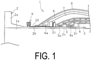
FIG. 1 is an explanatory cross-sectional view illustrating a marine hose with a fluid leakage detector according to an embodiment of the present invention. -
FIG. 2 is an explanatory diagram illustrating a use state of the marine hose inFIG. 1 . -
FIG. 3 is an explanatory diagram illustrating the fluid leakage detector inFIG. 1 in a longitudinal cross-sectional view. -
FIG. 4 is an explanatory diagram illustrating the fluid leakage detector inFIG. 3 in a plan view. -
FIG. 5 is an explanatory diagram illustrating the fluid leakage detector inFIG. 3 when fluid leakage occurs. -
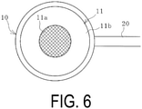
FIG. 6 is an explanatory diagram illustrating the fluid leakage detector inFIG. 5 in a plan view. -
FIG. 7 is an explanatory diagram illustrating another embodiment of a fluid leakage detector in a longitudinal cross-sectional view. -
FIG. 8 is an explanatory diagram illustrating the fluid leakage detector inFIG. 7 in a plan view. -
FIG. 9 is an explanatory diagram illustrating the fluid leakage detector inFIG. 7 when fluid leakage occurs. -
FIG. 10 is an explanatory diagram illustrating the fluid leakage detector inFIG. 9 in a plan view. - A fluid leakage detector of a marine hose according to embodiments of the present invention will be described below based on the embodiments illustrated in the drawings.
- The
marine hose 1 illustrated inFIGS. 1 and2 includes a fluid leakage detector 9 (hereinafter referred to as a detector 9) of an embodiment of the present invention. Themarine hose 1 includes, on its each end, a connectingend portion 2 to connect anothermarine hose 1, and the connectingend portion 2 includes anipple 2b having a flange 2a at one end. An inner surface rubber layer 3, a main reinforcing layer 4, a body wire layer 5, and anauxiliary reinforcing layer 6 are wound and layered in order from an inner circumference side toward an outer circumference side on an outer circumferential surface of thenipple 2b, and the outermost circumference is covered with acover rubber layer 8. Afluid retention layer 7 is formed between the body wire layer 5 and theauxiliary reinforcing layer 6 to provide a space. The inner circumference side of the inner surface rubber layer 3 serves as a fluid flow path 1a for a transport fluid L to flow. - The inner surface rubber layer 3 that contacts the transport fluid L is formed of, for example, nitrile rubber or the like having excellent oil resistance. The body wire layer 5 is formed by winding metal wires in a spirallike manner around a rubber layer of the outer circumference of the main reinforcing layer 4 at predetermined intervals. Each of the reinforcing
layers 4, 6 is formed by layering a plurality of reinforcing cord layers in which reinforcing cords are covered with rubber. - The main reinforcing layer 4, the body wire layer 5, and the
auxiliary reinforcing layer 6 are fixed to thenipple 2b byrespective nipple wires layers 4, 5, and 6 and, for example, afixing ring 2c disposed projecting from the outer circumferential surface of thenipple 2b. Thefluid retention layer 7 functions to temporarily store the transport fluid L leaked out from the main reinforcing layer 4. Thecover rubber layer 8 is formed of a non-water-permeable material such as rubber and has a line pattern or the like having excellent visibility on the surface of thecover rubber layer 8. - Among
marine hoses 1, a submarine hose may be connected to anoffshore tanker 21 as illustrated inFIG. 2 to be installed extending vertically in water or installed extending horizontally in a lying state remaining submerged in water. On the other hand, in the case of a floating hose, a buoyant material layer is provided between the layers of theauxiliary reinforcing layer 6 and thecover rubber layer 8 to be installed extending horizontally in a lying state floating on the sea water. Thedetector 9 of an embodiment of the present invention can be applied to both types of a submarine hose and a floating hose. - The
detector 9 illustrated inFIG. 3 includes acommunication pipe 20 that communicates with thefluid retention layer 7 and extends on a hose surface, acasing 10 having a hollow portion, a detectingbody 12 housed in the hollow portion of thecasing 10, and awindow portion 11 isolating the hollow portion of thecasing 10 from outside thecasing 10. Thedetector 9 further includes apartition portion 11a disposed on a surface on the hollow portion side of thewindow portion 11, and amovement mechanism 13. - The
casing 10 is attached on the hose surface at a predetermined position by an appropriate fixing member. As in this embodiment, thecasing 10 is preferably attached on the exposed outer circumferential surface of thenipple 2b because this stabilizes thecasing 10. In this embodiment, thecasing 10 includes ahousing portion 10a having a hollow portion with awindow portion 11, and a fillingportion 10b having a hollow portion, and the hollow portions of theportions membrane portion 15 made of rubber or the like. - One end portion of the
communication pipe 20 is disposed inside thefluid retention layer 7, and the other end portion is disposed in the hollow portion of the casing 10 (thefilling portion 10b). Accordingly, thefluid retention layer 7 and the casing 10 (thefilling portion 10b) are in communication via thecommunication pipe 20. - The
window portion 11 includes apartition portion 11a disposed on a surface on the hollow portion side, and aprotection portion 11b disposed on an outer surface (a surface on a side opposite to the hollow portion) to cover thepartition portion 11a. Thepartition portion 11a is formed of a fiber optic plate (hereinafter referred to as "FOP"). - An FOP is an assembly in which a multiplicity of optical fibers are apposed to form an integrated bundle, and is an optical device having opposite end surfaces oriented in a fiber longitudinal direction. Each of optical fiber includes a core glass and a clad glass on the outer circumference of the core glass, and total reflection occurs at the boundary between the core glass and the clad glass because of difference in refractive indices between the core glass and the clad glass and thus the light travels inside the core glass. Light escaped out of the optical fiber without totally reflecting is absorbed by the absorber glass and does not reach adjacent optical fibers. Therefore, an object that is brought into proximity (contact) with one end surface of the FOP can be visually recognized as an image of the object without compromising resolution at the other end surface of the FOP. On the other hand, when the object is distant from the one end surface of the FOP, the image of the object cannot be visually recognized on the other end surface of the FOP. The
detector 9 takes advantage of this characteristics of the FOP. - The
protection portion 11b layered on the outer surface (upper surface) of thepartition portion 11a completely covers the upper surface of thepartition portion 11a. Theprotection portion 11b is a transparent plate formed of polycarbonate having excellent shock resistance. - The
movement mechanism 13 moves at least one of the detectingbody 12 or thepartition portion 11a in accordance with a change in pressure P acting on the inside of thecasing 10 through thecommunication pipe 20, and brings the detectingbody 12 and thepartition portion 11a to be in proximity to or distant from each other. In this embodiment, themovement mechanism 13 moves the detectingbody 12 with respect to thepartition portion 11a that is fixed in accordance with a change in the pressure P. - Specifically, the
movement mechanism 13 includes themembrane portion 15 described above, arod 14 set to be mounted on themembrane portion 15, and asupport portion 16 supporting therod 14. Thesupport portion 16 includes a through-hole through which therod 14 is inserted, and supports therod 14 to be movable in a direction in which therod 14 is brought to be in proximity to or distant from thepartition portion 11a. The detectingbody 12 is attached to a tip of therod 14. The detectingbody 12, therod 14, and thesupport portion 16 are housed in the hollow portion of thehousing portion 10a. - When the
marine hose 1 is normal, that is, the main reinforcing layer 4 is not damaged, there is substantially no change in the internal pressure of the fillingportion 10b. Therefore, as illustrated inFIG. 3 , in thedetector 9, as in an initial configuration, the detectingbody 12 is disposed at a position spaced apart from thepartition portion 11a. Therefore, even when visually observed through thewindow portion 11 from the outside, the detectingbody 12 cannot be visually recognized as illustrated inFIG. 4 because of the characteristics of the FOP that forms thepartition portion 11a. - When the main reinforcing layer 4 is damaged and the transport fluid L leaks into the
fluid retention layer 7, the leaked transport fluid L flows into thecommunication pipe 20 as illustrated inFIG. 5 . Thereafter, the transport fluid L enters the casing 10 (the fillingportion 10b). Leakage of the transport fluid L into thefluid retention layer 7 increases the pressure P acting on the hollow portion of the fillingportion 10b through thecommunication pipe 20. Due to this pressure change, themembrane portion 15 expands (deforms) toward the hollow portion of thehousing portion 10a that remains at the initial internal pressure. In cooperation with the expansion of themembrane portion 15, therod 14 moves in proximity to thepartition portion 11a, and thus the detectingbody 12 contacts thepartition portion 11a. As a result, when thewindow portion 11 is visually observed through from the outside, as illustrated inFIG. 6 , the detectingbody 12 can be visually recognized because of the characteristics of the FOP that forms thepartition portion 11a. InFIG. 6 , the surface of the detectingbody 12 is illustrated in a grid-like shape for clarity. The surface of the actual detectingbody 12 is preferably colored to be easily visually recognized in water. - When the detecting
body 12 is not in proximity to thepartition portion 11a, the detectingbody 12 cannot be visually recognized through thepartition portion 11a. In other words, in order to determine whether the transport fluid L has leaked into thefluid retention layer 7, it is only required to check whether the detectingbody 12 is visually recognized by visually observing thewindow portion 11, and thus, it is advantageous for more reliably determining the occurrence of leakage of the transport fluid L. - As in this embodiment, when the
movement mechanism 13 moves only the detectingbody 12 of thepartition portion 11a and the detectingbody 12 in accordance with the change in the pressure P, it is sufficient that the detectingbody 12 can simply be moved only in the hollow portion of thecasing 10. Accordingly, thedetector 9 having a compact and simple structure is easily obtained. - As in an embodiment illustrated in
FIGS. 7 and8 , thepartition portion 11a can be moved in accordance with the change in the pressure P with respect to the detectingbody 12 that is fixed. This embodiment includes ahousing portion 10a having a hollow portion with awindow portion 11, and a fillingportion 10b having a cylindrical hollow portion, and the hollow portions of theportions membrane portion 15. - One end portion of the
communication pipe 20 is disposed inside thefluid retention layer 7, and the other end portion is disposed in the hollow portion of the casing 10 (the fillingportion 10b). Accordingly, thefluid retention layer 7 and the casing 10 (the fillingportion 10b) are in communication via thecommunication pipe 20. - The
window portion 11 includes apartition portion 11a formed of FOP and aprotection portion 11b covering an upper side surface of thepartition portion 11a. The detectingbody 12 is attached to a tip of a supportingcolumn 12a embedded in the fillingportion 10b and is disposed in the hollow portion of thehousing portion 10a. The detectingbody 12 is at a position spaced apart from thepartition portion 11a below thepartition portion 11a. - The
movement mechanism 13 includes themembrane portion 15 described above, arod 14 set to be mounted on themembrane portion 15, asupport portion 16 that supports therod 14, a mounting table 18 on which thepartition portion 11b is mounted, and anarm portion 17 that connects therod 14 and the mounting table 18 and is axially supported by asupport shaft 19. A plurality of therods 14 are disposed at intervals in the circumferential direction in a plan view. - The
support portion 16 has a hole shape that guides eachrod 14. Thesupport shaft 19 is disposed between the mounting table 18 having an annular shape and eachrod 14. Each of thesupport shafts 19 allows thearm portion 17 to pivot up and down about thesupport shaft 19. One end portion of eacharm portion 17 is rotatably connected to the mounting table 18 and the other end portion of eacharm portion 17 is rotatably connected to therod 14. Therod 14, thesupport portion 16, the mounting table 18, thesupport shaft 19, and thearm portion 17 are housed in the hollow portion of thehousing portion 10a. - When the
marine hose 1 is normal, that is, the main reinforcing layer 4 is not damaged, in thedetector 9, as illustrated inFIG. 7 , as in an initial configuration, thepartition portion 11a is mounted on the mounting table 18 and above the detectingbody 12 that is supported by the supportingcolumn 12a and spaced apart from the detectingbody 12. Therefore, even when thewindow portion 11 is visually observed from the outside, the detectingbody 12 cannot be visually recognized as illustrated inFIG. 8 because of the characteristics of the FOP that forms thepartition portion 11a. - When the main reinforcing layer 4 is damaged and the transport fluid L leaks into the
fluid retention layer 7, the pressure P acting on the hollow portion of the fillingportion 10b through thecommunication pipe 20 increases, similar to the previous embodiment. Due to this pressure change, as illustrated inFIG. 9 , themembrane portion 15 moves (deforms) toward the hollow portion of thehousing portion 10a while themembrane portion 15 remains at the initial internal pressure. When therod 14 moves upward in cooperation therewith, thearm portion 17 pivots up and down about thesupport shaft 19. Due to this pivoting of thearm portion 17, thepartition portion 11a mounted on the mounting table 18 moves away from the lower surface of theprotection portion 11b and in proximity to the detectingbody 12, and contacts the detectingbody 12. Thepartition portion 11a is preferably engaged with the mounting table 18 using a guide and guide groove or the like that can slide in the horizontal direction and constrains vertical movement so that thepartition portion 11a does not separate vertically with respect to the mounting table 18. - Consequently, when the
window portion 11 is visually observed from the outside, the detectingbody 12 can be visually recognized as illustrated inFIG. 10 because of the characteristics of the FOP that forms thepartition portion 11a. InFIG. 10 , the surface of the detectingbody 12 is illustrated in a grid-like shape for clarity. The surface of the actual detectingbody 12 is preferably colored to be easily visually recognized in water. - As described above, the
detector 9 according to an embodiment of the present invention moves thepartition portion 11a and the detectingbody 12 to be in proximity to or distant from each other to clearly divide states of the detectingbody 12 into two states, a state in which the detectingbody 12 can be visually recognized and a state in which the detectingbody 12 cannot be visually recognized by taking advantage of the characteristics of the FOP. Accordingly, difficulties in the determination of whether the detectingbody 12 is in either state by a diver and the like visually observing thewindow portion 11 from the outside are avoided. - The numerical aperture (N.A.) of the FOP forming the
partition portion 11a is greater than or equal to 0.9, and more preferably 1.0. When the numerical aperture (N.A.) is too small, the detectingbody 12 is less likely to be visually recognized unless visually observed from the direction orthogonal to thepartition portion 11a (the direction viewed from directly above). In other words, when the numerical aperture (N.A.) is greater than or equal to 0.9, the detectingbody 12 is easily visually recognized even when visually observed from an oblique direction with respect to thepartition portion 11a. Thus, setting the numerical aperture (N.A.) to be greater than or equal to 0.9 or to be 1.0 makes it easy for a diver to visually recognize the detectingbody 12. - In the
detector 9 illustrated inFIG. 5 , theprotection portion 11b can be omitted, however, theprotection portion 11b is preferably provided because thepartition portion 11a is prevented from being damaged by foreign materials from the outside or the like. In addition, because theprotection portion 11b is formed of polycarbonate, it is difficult for scratches to occur, and it is advantageous to ensure transparency over a long period of time. Accordingly, visual check of the detectingbody 12 can be performed stably for a long period of time. - In the case of a submarine hose in which the
marine hose 1 is used submerged in water, the detecting body is visually checked by a diver underwater that has poor visibility compared to that above water. In thedetector 9 according to an embodiment of the present invention, even underwater, it is only required to visually observe thewindow portion 11 to check whether the detectingbody 12 is visually recognized, it is advantageous to avoid an erroneous recognition (erroneous determination). - The internal structure of the
marine hose 1 differs in the number of reinforcing layers and the type of multilayer structures depending on the required performance and is not limited to the structure illustrated in the embodiments. Embodiments of the present invention can be applied tomarine hoses 1 of various structures with afluid retention layer 7. -
- 1
- Marine hose
1a Fluid flow path - 2
- Connecting end portion
2a Flange
2b Nipple
2c Fixing ring - 3
- Inner surface rubber layer
- 4
- Main reinforcing layer
4a Nipple wire - 5
- Body wire layer
5a Nipple wire - 6
- Auxiliary reinforcing layer
6a Nipple wire - 7
- Fluid retention layer
- 8
- Cover rubber layer
- 9
- Fluid leakage detector
- 10
- Casing
10a Housing portion
10b Filling portion - 11
- Window portion
11a Partition portion (FOP)
11b Protection portion - 12
- Detecting body
12a Supporting column - 13
- Movement mechanism
- 14
- Rod
- 15
- Membrane portion
- 16
- Support portion
- 17
- Arm portion
- 18
- Mounting table
- 19
- Support shaft
- 20
- Communication pipe
- 21
- Tanker
Claims (5)
- A fluid leakage detector of a marine hose, comprising:a communication pipe that communicates with a fluid retention layer formed between reinforcing layers layered on an outer circumference side of a fluid flow path of the marine hose and extends to a hose surface;a casing having a hollow portion that communicates with the communication pipe and that is disposed on the hose surface;a detecting body housed in the hollow portion; anda window portion isolating the hollow portion from outside the casing;the fluid leakage detector of the marine hose further comprising:a partition portion formed of a fiber optic plate that is disposed on a surface on the hollow portion side of the window portion; anda movement mechanism that brings the detecting body and the partition portion to be in proximity to or distant from each other by moving at least one of the detecting body or the partition portion in accordance with a change in pressure acting on the hollow portion through the communication pipe.
- The fluid leakage detector of the marine hose according to claim 1, wherein the movement mechanism moves the detecting body in accordance with a change in the pressure with respect to the partition portion that is fixed.
- The fluid leakage detector of the marine hose according to claim 1 or 2, wherein a numerical aperture of the fiber optic plate is greater than or equal to 0.9.
- The fluid leakage detector of the marine hose according to any one of claims 1 to 3, further comprising a protection portion made of polycarbonate that covers an outer surface of the partition portion.
- The fluid leakage detector of the marine hose according to any one of claims 1 to 4, wherein the marine hose is a submarine hose used submerged in water.
Applications Claiming Priority (2)
| Application Number | Priority Date | Filing Date | Title |
|---|---|---|---|
| JP2019044365A JP7225949B2 (en) | 2019-03-12 | 2019-03-12 | Marine hose fluid leak detector |
| PCT/JP2019/045561 WO2020183803A1 (en) | 2019-03-12 | 2019-11-21 | Marine hose fluid leakage detector |
Publications (3)
| Publication Number | Publication Date |
|---|---|
| EP3940363A1 true EP3940363A1 (en) | 2022-01-19 |
| EP3940363A4 EP3940363A4 (en) | 2022-05-18 |
| EP3940363B1 EP3940363B1 (en) | 2023-03-01 |
Family
ID=72426359
Family Applications (1)
| Application Number | Title | Priority Date | Filing Date |
|---|---|---|---|
| EP19918938.2A Active EP3940363B1 (en) | 2019-03-12 | 2019-11-21 | Marine hose fluid leakage detector |
Country Status (5)
| Country | Link |
|---|---|
| EP (1) | EP3940363B1 (en) |
| JP (1) | JP7225949B2 (en) |
| CN (1) | CN113544483B (en) |
| BR (1) | BR112021016794B1 (en) |
| WO (1) | WO2020183803A1 (en) |
Cited By (2)
| Publication number | Priority date | Publication date | Assignee | Title |
|---|---|---|---|---|
| EP4563876A4 (en) * | 2022-07-26 | 2025-10-01 | Yokohama Rubber Co Ltd | Housing and cap assembly for a marine hose fluid leak detector and marine hose fluid leak detection system |
| EP4428431A4 (en) * | 2021-11-05 | 2025-10-22 | Yokohama Rubber Co Ltd | System for detecting fluid leaks in a marine hose and method for manufacturing the same |
Family Cites Families (16)
| Publication number | Priority date | Publication date | Assignee | Title |
|---|---|---|---|---|
| GB1039515A (en) * | 1962-07-24 | 1966-08-17 | Power Aux Ies Ltd | Improvements in or relating to flexible pressure tubes and ducts |
| US3703879A (en) * | 1971-04-06 | 1972-11-28 | Charles K Huthsing Jr | Pressure indicator |
| JPS54163423A (en) * | 1978-06-14 | 1979-12-26 | Bridgestone Tire Co Ltd | Reinforced rubber hose |
| EP0064807A3 (en) * | 1981-03-26 | 1983-01-05 | Johnson Matthey Public Limited Company | Improvements in or relating to profile change sensors |
| JPH10148280A (en) * | 1996-11-19 | 1998-06-02 | Bridgestone Corp | Hose with leak alarm device |
| JP2001132876A (en) * | 1999-11-04 | 2001-05-18 | Bridgestone Corp | Marine hose with leakage detecting function |
| AU769067B2 (en) * | 1999-11-23 | 2004-01-15 | Phoenix Ag | Double walled tube with leak display device |
| KR20000072443A (en) * | 2000-08-31 | 2000-12-05 | 송재원 | Uncut, non-lattice pressure gauge using side polished fiber and multimode planar wave coupler |
| JP3817459B2 (en) * | 2001-05-01 | 2006-09-06 | 横浜ゴム株式会社 | Fluid transfer hose |
| JP2002350111A (en) * | 2001-05-25 | 2002-12-04 | Hamamatsu Photonics Kk | Observation apparatus using light and x-ray, exposure apparatus and exposure method |
| JP4747834B2 (en) * | 2005-12-27 | 2011-08-17 | 横浜ゴム株式会社 | Marine hose fluid leak detection system |
| US7509841B2 (en) * | 2006-07-14 | 2009-03-31 | Veyance Technologies, Inc. | Flexible leak detection system and method for double carcass hose |
| JP5104979B2 (en) * | 2011-05-09 | 2012-12-19 | 横浜ゴム株式会社 | Fluid transfer hose |
| JP2014122677A (en) * | 2012-12-21 | 2014-07-03 | Yokohama Rubber Co Ltd:The | Marine hose, and its manufacturing method |
| JP6623801B2 (en) * | 2016-02-04 | 2019-12-25 | 横浜ゴム株式会社 | Marine hose condition monitoring system |
| JP6623800B2 (en) * | 2016-02-04 | 2019-12-25 | 横浜ゴム株式会社 | Marine hose |
-
2019
- 2019-03-12 JP JP2019044365A patent/JP7225949B2/en active Active
- 2019-11-21 EP EP19918938.2A patent/EP3940363B1/en active Active
- 2019-11-21 CN CN201980093535.9A patent/CN113544483B/en active Active
- 2019-11-21 BR BR112021016794-3A patent/BR112021016794B1/en active IP Right Grant
- 2019-11-21 WO PCT/JP2019/045561 patent/WO2020183803A1/en not_active Ceased
Cited By (2)
| Publication number | Priority date | Publication date | Assignee | Title |
|---|---|---|---|---|
| EP4428431A4 (en) * | 2021-11-05 | 2025-10-22 | Yokohama Rubber Co Ltd | System for detecting fluid leaks in a marine hose and method for manufacturing the same |
| EP4563876A4 (en) * | 2022-07-26 | 2025-10-01 | Yokohama Rubber Co Ltd | Housing and cap assembly for a marine hose fluid leak detector and marine hose fluid leak detection system |
Also Published As
| Publication number | Publication date |
|---|---|
| WO2020183803A1 (en) | 2020-09-17 |
| EP3940363B1 (en) | 2023-03-01 |
| EP3940363A4 (en) | 2022-05-18 |
| JP7225949B2 (en) | 2023-02-21 |
| JP2020148519A (en) | 2020-09-17 |
| BR112021016794A2 (en) | 2021-10-19 |
| BR112021016794B1 (en) | 2022-08-23 |
| CN113544483A (en) | 2021-10-22 |
| CN113544483B (en) | 2022-07-26 |
Similar Documents
| Publication | Publication Date | Title |
|---|---|---|
| EP3940363B1 (en) | Marine hose fluid leakage detector | |
| ES2683671T3 (en) | Pipe apparatus and method | |
| US6549488B2 (en) | Fiber-optic hydrophone | |
| CN1317102A (en) | Fiber Optic Cables for Harsh Environments | |
| EA013831B1 (en) | Leak detector using an optical fibre | |
| EP3412951B1 (en) | Marine hose status monitoring system | |
| EP3412952B1 (en) | Marine hose status monitoring system | |
| JPS648770B2 (en) | ||
| CN113568118A (en) | Self-inhibition type anti-bending optical cable | |
| JP4872972B2 (en) | Marine hose fluid leak detector | |
| CN115096425A (en) | Optical fiber hydrophone | |
| JP4076338B2 (en) | Fluid transfer hose | |
| JP4747834B2 (en) | Marine hose fluid leak detection system | |
| US7687764B1 (en) | Fiber optic sensors for composite pressure tanks with micro bend pinch points | |
| CN119164882A (en) | A corrosion-resistant liquid detection flow cell | |
| KR102121742B1 (en) | Device and method for fuel leakage detection | |
| JP2024094906A (en) | Cable and cable water ingress detection device | |
| US20090169151A1 (en) | Ferrule for an evanescence field sensor line | |
| JPH04148836A (en) | Liquid-leakage detecting apparatus | |
| CN220651676U (en) | Fully dry buoyancy-resistant sensing tail cable | |
| KR101691888B1 (en) | optic adapter for non-contact optic connector | |
| JP6274895B2 (en) | Communication cable closure | |
| JP4609836B2 (en) | Optical fiber sensor | |
| KR102137255B1 (en) | Optical Fiber Sensor for Submersion and Leakage Detection and Sensing System Using Thereof | |
| JPS5939633Y2 (en) | Underwater oil pollution monitoring device |
Legal Events
| Date | Code | Title | Description |
|---|---|---|---|
| STAA | Information on the status of an ep patent application or granted ep patent |
Free format text: STATUS: THE INTERNATIONAL PUBLICATION HAS BEEN MADE |
|
| PUAI | Public reference made under article 153(3) epc to a published international application that has entered the european phase |
Free format text: ORIGINAL CODE: 0009012 |
|
| STAA | Information on the status of an ep patent application or granted ep patent |
Free format text: STATUS: REQUEST FOR EXAMINATION WAS MADE |
|
| 17P | Request for examination filed |
Effective date: 20211008 |
|
| AK | Designated contracting states |
Kind code of ref document: A1 Designated state(s): AL AT BE BG CH CY CZ DE DK EE ES FI FR GB GR HR HU IE IS IT LI LT LU LV MC MK MT NL NO PL PT RO RS SE SI SK SM TR |
|
| A4 | Supplementary search report drawn up and despatched |
Effective date: 20220419 |
|
| RIC1 | Information provided on ipc code assigned before grant |
Ipc: G01L 19/08 20060101ALI20220411BHEP Ipc: G01L 7/08 20060101ALI20220411BHEP Ipc: F16L 55/00 20060101ALI20220411BHEP Ipc: F16L 11/12 20060101ALI20220411BHEP Ipc: G01M 3/28 20060101AFI20220411BHEP |
|
| DAV | Request for validation of the european patent (deleted) | ||
| DAX | Request for extension of the european patent (deleted) | ||
| GRAP | Despatch of communication of intention to grant a patent |
Free format text: ORIGINAL CODE: EPIDOSNIGR1 |
|
| STAA | Information on the status of an ep patent application or granted ep patent |
Free format text: STATUS: GRANT OF PATENT IS INTENDED |
|
| RIC1 | Information provided on ipc code assigned before grant |
Ipc: G01L 19/08 20060101ALI20220919BHEP Ipc: G01L 7/08 20060101ALI20220919BHEP Ipc: G01M 3/28 20060101AFI20220919BHEP |
|
| INTG | Intention to grant announced |
Effective date: 20221018 |
|
| RIN1 | Information on inventor provided before grant (corrected) |
Inventor name: ISHIBASHI YUSUKE Inventor name: TSUKAZAKI TAKAHIRO |
|
| GRAS | Grant fee paid |
Free format text: ORIGINAL CODE: EPIDOSNIGR3 |
|
| GRAA | (expected) grant |
Free format text: ORIGINAL CODE: 0009210 |
|
| STAA | Information on the status of an ep patent application or granted ep patent |
Free format text: STATUS: THE PATENT HAS BEEN GRANTED |
|
| AK | Designated contracting states |
Kind code of ref document: B1 Designated state(s): AL AT BE BG CH CY CZ DE DK EE ES FI FR GB GR HR HU IE IS IT LI LT LU LV MC MK MT NL NO PL PT RO RS SE SI SK SM TR |
|
| REG | Reference to a national code |
Ref country code: GB Ref legal event code: FG4D |
|
| REG | Reference to a national code |
Ref country code: CH Ref legal event code: EP Ref country code: AT Ref legal event code: REF Ref document number: 1551283 Country of ref document: AT Kind code of ref document: T Effective date: 20230315 |
|
| REG | Reference to a national code |
Ref country code: DE Ref legal event code: R096 Ref document number: 602019026025 Country of ref document: DE |
|
| REG | Reference to a national code |
Ref country code: IE Ref legal event code: FG4D |
|
| P01 | Opt-out of the competence of the unified patent court (upc) registered |
Effective date: 20230512 |
|
| REG | Reference to a national code |
Ref country code: LT Ref legal event code: MG9D |
|
| REG | Reference to a national code |
Ref country code: NL Ref legal event code: MP Effective date: 20230301 |
|
| PG25 | Lapsed in a contracting state [announced via postgrant information from national office to epo] |
Ref country code: RS Free format text: LAPSE BECAUSE OF FAILURE TO SUBMIT A TRANSLATION OF THE DESCRIPTION OR TO PAY THE FEE WITHIN THE PRESCRIBED TIME-LIMIT Effective date: 20230301 Ref country code: NO Free format text: LAPSE BECAUSE OF FAILURE TO SUBMIT A TRANSLATION OF THE DESCRIPTION OR TO PAY THE FEE WITHIN THE PRESCRIBED TIME-LIMIT Effective date: 20230601 Ref country code: LV Free format text: LAPSE BECAUSE OF FAILURE TO SUBMIT A TRANSLATION OF THE DESCRIPTION OR TO PAY THE FEE WITHIN THE PRESCRIBED TIME-LIMIT Effective date: 20230301 Ref country code: LT Free format text: LAPSE BECAUSE OF FAILURE TO SUBMIT A TRANSLATION OF THE DESCRIPTION OR TO PAY THE FEE WITHIN THE PRESCRIBED TIME-LIMIT Effective date: 20230301 Ref country code: HR Free format text: LAPSE BECAUSE OF FAILURE TO SUBMIT A TRANSLATION OF THE DESCRIPTION OR TO PAY THE FEE WITHIN THE PRESCRIBED TIME-LIMIT Effective date: 20230301 Ref country code: ES Free format text: LAPSE BECAUSE OF FAILURE TO SUBMIT A TRANSLATION OF THE DESCRIPTION OR TO PAY THE FEE WITHIN THE PRESCRIBED TIME-LIMIT Effective date: 20230301 |
|
| REG | Reference to a national code |
Ref country code: AT Ref legal event code: MK05 Ref document number: 1551283 Country of ref document: AT Kind code of ref document: T Effective date: 20230301 |
|
| PG25 | Lapsed in a contracting state [announced via postgrant information from national office to epo] |
Ref country code: SE Free format text: LAPSE BECAUSE OF FAILURE TO SUBMIT A TRANSLATION OF THE DESCRIPTION OR TO PAY THE FEE WITHIN THE PRESCRIBED TIME-LIMIT Effective date: 20230301 Ref country code: PL Free format text: LAPSE BECAUSE OF FAILURE TO SUBMIT A TRANSLATION OF THE DESCRIPTION OR TO PAY THE FEE WITHIN THE PRESCRIBED TIME-LIMIT Effective date: 20230301 Ref country code: NL Free format text: LAPSE BECAUSE OF FAILURE TO SUBMIT A TRANSLATION OF THE DESCRIPTION OR TO PAY THE FEE WITHIN THE PRESCRIBED TIME-LIMIT Effective date: 20230301 Ref country code: GR Free format text: LAPSE BECAUSE OF FAILURE TO SUBMIT A TRANSLATION OF THE DESCRIPTION OR TO PAY THE FEE WITHIN THE PRESCRIBED TIME-LIMIT Effective date: 20230602 Ref country code: FI Free format text: LAPSE BECAUSE OF FAILURE TO SUBMIT A TRANSLATION OF THE DESCRIPTION OR TO PAY THE FEE WITHIN THE PRESCRIBED TIME-LIMIT Effective date: 20230301 |
|
| PG25 | Lapsed in a contracting state [announced via postgrant information from national office to epo] |
Ref country code: SM Free format text: LAPSE BECAUSE OF FAILURE TO SUBMIT A TRANSLATION OF THE DESCRIPTION OR TO PAY THE FEE WITHIN THE PRESCRIBED TIME-LIMIT Effective date: 20230301 Ref country code: RO Free format text: LAPSE BECAUSE OF FAILURE TO SUBMIT A TRANSLATION OF THE DESCRIPTION OR TO PAY THE FEE WITHIN THE PRESCRIBED TIME-LIMIT Effective date: 20230301 Ref country code: PT Free format text: LAPSE BECAUSE OF FAILURE TO SUBMIT A TRANSLATION OF THE DESCRIPTION OR TO PAY THE FEE WITHIN THE PRESCRIBED TIME-LIMIT Effective date: 20230703 Ref country code: EE Free format text: LAPSE BECAUSE OF FAILURE TO SUBMIT A TRANSLATION OF THE DESCRIPTION OR TO PAY THE FEE WITHIN THE PRESCRIBED TIME-LIMIT Effective date: 20230301 Ref country code: CZ Free format text: LAPSE BECAUSE OF FAILURE TO SUBMIT A TRANSLATION OF THE DESCRIPTION OR TO PAY THE FEE WITHIN THE PRESCRIBED TIME-LIMIT Effective date: 20230301 Ref country code: AT Free format text: LAPSE BECAUSE OF FAILURE TO SUBMIT A TRANSLATION OF THE DESCRIPTION OR TO PAY THE FEE WITHIN THE PRESCRIBED TIME-LIMIT Effective date: 20230301 |
|
| RAP4 | Party data changed (patent owner data changed or rights of a patent transferred) |
Owner name: THE YOKOHAMA RUBBER CO., LTD. |
|
| PG25 | Lapsed in a contracting state [announced via postgrant information from national office to epo] |
Ref country code: SK Free format text: LAPSE BECAUSE OF FAILURE TO SUBMIT A TRANSLATION OF THE DESCRIPTION OR TO PAY THE FEE WITHIN THE PRESCRIBED TIME-LIMIT Effective date: 20230301 Ref country code: IS Free format text: LAPSE BECAUSE OF FAILURE TO SUBMIT A TRANSLATION OF THE DESCRIPTION OR TO PAY THE FEE WITHIN THE PRESCRIBED TIME-LIMIT Effective date: 20230701 |
|
| REG | Reference to a national code |
Ref country code: DE Ref legal event code: R097 Ref document number: 602019026025 Country of ref document: DE |
|
| PLBE | No opposition filed within time limit |
Free format text: ORIGINAL CODE: 0009261 |
|
| STAA | Information on the status of an ep patent application or granted ep patent |
Free format text: STATUS: NO OPPOSITION FILED WITHIN TIME LIMIT |
|
| PG25 | Lapsed in a contracting state [announced via postgrant information from national office to epo] |
Ref country code: SI Free format text: LAPSE BECAUSE OF FAILURE TO SUBMIT A TRANSLATION OF THE DESCRIPTION OR TO PAY THE FEE WITHIN THE PRESCRIBED TIME-LIMIT Effective date: 20230301 Ref country code: DK Free format text: LAPSE BECAUSE OF FAILURE TO SUBMIT A TRANSLATION OF THE DESCRIPTION OR TO PAY THE FEE WITHIN THE PRESCRIBED TIME-LIMIT Effective date: 20230301 |
|
| 26N | No opposition filed |
Effective date: 20231204 |
|
| REG | Reference to a national code |
Ref country code: DE Ref legal event code: R119 Ref document number: 602019026025 Country of ref document: DE |
|
| REG | Reference to a national code |
Ref country code: CH Ref legal event code: PL |
|
| PG25 | Lapsed in a contracting state [announced via postgrant information from national office to epo] |
Ref country code: MC Free format text: LAPSE BECAUSE OF FAILURE TO SUBMIT A TRANSLATION OF THE DESCRIPTION OR TO PAY THE FEE WITHIN THE PRESCRIBED TIME-LIMIT Effective date: 20230301 |
|
| PG25 | Lapsed in a contracting state [announced via postgrant information from national office to epo] |
Ref country code: LU Free format text: LAPSE BECAUSE OF NON-PAYMENT OF DUE FEES Effective date: 20231121 |
|
| PG25 | Lapsed in a contracting state [announced via postgrant information from national office to epo] |
Ref country code: CH Free format text: LAPSE BECAUSE OF NON-PAYMENT OF DUE FEES Effective date: 20231130 |
|
| PG25 | Lapsed in a contracting state [announced via postgrant information from national office to epo] |
Ref country code: MC Free format text: LAPSE BECAUSE OF FAILURE TO SUBMIT A TRANSLATION OF THE DESCRIPTION OR TO PAY THE FEE WITHIN THE PRESCRIBED TIME-LIMIT Effective date: 20230301 Ref country code: LU Free format text: LAPSE BECAUSE OF NON-PAYMENT OF DUE FEES Effective date: 20231121 Ref country code: CH Free format text: LAPSE BECAUSE OF NON-PAYMENT OF DUE FEES Effective date: 20231130 |
|
| REG | Reference to a national code |
Ref country code: BE Ref legal event code: MM Effective date: 20231130 |
|
| REG | Reference to a national code |
Ref country code: IE Ref legal event code: MM4A |
|
| PG25 | Lapsed in a contracting state [announced via postgrant information from national office to epo] |
Ref country code: DE Free format text: LAPSE BECAUSE OF NON-PAYMENT OF DUE FEES Effective date: 20240601 Ref country code: IE Free format text: LAPSE BECAUSE OF NON-PAYMENT OF DUE FEES Effective date: 20231121 |
|
| PG25 | Lapsed in a contracting state [announced via postgrant information from national office to epo] |
Ref country code: BE Free format text: LAPSE BECAUSE OF NON-PAYMENT OF DUE FEES Effective date: 20231130 |
|
| PG25 | Lapsed in a contracting state [announced via postgrant information from national office to epo] |
Ref country code: FR Free format text: LAPSE BECAUSE OF NON-PAYMENT OF DUE FEES Effective date: 20231130 |
|
| PG25 | Lapsed in a contracting state [announced via postgrant information from national office to epo] |
Ref country code: IE Free format text: LAPSE BECAUSE OF NON-PAYMENT OF DUE FEES Effective date: 20231121 Ref country code: FR Free format text: LAPSE BECAUSE OF NON-PAYMENT OF DUE FEES Effective date: 20231130 Ref country code: DE Free format text: LAPSE BECAUSE OF NON-PAYMENT OF DUE FEES Effective date: 20240601 Ref country code: BE Free format text: LAPSE BECAUSE OF NON-PAYMENT OF DUE FEES Effective date: 20231130 |
|
| PG25 | Lapsed in a contracting state [announced via postgrant information from national office to epo] |
Ref country code: BG Free format text: LAPSE BECAUSE OF FAILURE TO SUBMIT A TRANSLATION OF THE DESCRIPTION OR TO PAY THE FEE WITHIN THE PRESCRIBED TIME-LIMIT Effective date: 20230301 |
|
| PG25 | Lapsed in a contracting state [announced via postgrant information from national office to epo] |
Ref country code: BG Free format text: LAPSE BECAUSE OF FAILURE TO SUBMIT A TRANSLATION OF THE DESCRIPTION OR TO PAY THE FEE WITHIN THE PRESCRIBED TIME-LIMIT Effective date: 20230301 |
|
| PG25 | Lapsed in a contracting state [announced via postgrant information from national office to epo] |
Ref country code: CY Free format text: LAPSE BECAUSE OF FAILURE TO SUBMIT A TRANSLATION OF THE DESCRIPTION OR TO PAY THE FEE WITHIN THE PRESCRIBED TIME-LIMIT; INVALID AB INITIO Effective date: 20191121 |
|
| PG25 | Lapsed in a contracting state [announced via postgrant information from national office to epo] |
Ref country code: HU Free format text: LAPSE BECAUSE OF FAILURE TO SUBMIT A TRANSLATION OF THE DESCRIPTION OR TO PAY THE FEE WITHIN THE PRESCRIBED TIME-LIMIT; INVALID AB INITIO Effective date: 20191121 |
|
| PG25 | Lapsed in a contracting state [announced via postgrant information from national office to epo] |
Ref country code: TR Free format text: LAPSE BECAUSE OF FAILURE TO SUBMIT A TRANSLATION OF THE DESCRIPTION OR TO PAY THE FEE WITHIN THE PRESCRIBED TIME-LIMIT Effective date: 20230301 |
|
| PGFP | Annual fee paid to national office [announced via postgrant information from national office to epo] |
Ref country code: GB Payment date: 20251001 Year of fee payment: 7 |
|
| PGFP | Annual fee paid to national office [announced via postgrant information from national office to epo] |
Ref country code: IT Payment date: 20251022 Year of fee payment: 7 |