EP3940309A1 - Damper opening/closing device - Google Patents
Damper opening/closing device Download PDFInfo
- Publication number
- EP3940309A1 EP3940309A1 EP20769422.5A EP20769422A EP3940309A1 EP 3940309 A1 EP3940309 A1 EP 3940309A1 EP 20769422 A EP20769422 A EP 20769422A EP 3940309 A1 EP3940309 A1 EP 3940309A1
- Authority
- EP
- European Patent Office
- Prior art keywords
- opening
- closing lid
- state
- contact
- closing
- Prior art date
- Legal status (The legal status is an assumption and is not a legal conclusion. Google has not performed a legal analysis and makes no representation as to the accuracy of the status listed.)
- Granted
Links
Images



Classifications
-
- B—PERFORMING OPERATIONS; TRANSPORTING
- B65—CONVEYING; PACKING; STORING; HANDLING THIN OR FILAMENTARY MATERIAL
- B65D—CONTAINERS FOR STORAGE OR TRANSPORT OF ARTICLES OR MATERIALS, e.g. BAGS, BARRELS, BOTTLES, BOXES, CANS, CARTONS, CRATES, DRUMS, JARS, TANKS, HOPPERS, FORWARDING CONTAINERS; ACCESSORIES, CLOSURES, OR FITTINGS THEREFOR; PACKAGING ELEMENTS; PACKAGES
- B65D88/00—Large containers
- B65D88/74—Large containers having means for heating, cooling, aerating or other conditioning of contents
- B65D88/741—Large containers having means for heating, cooling, aerating or other conditioning of contents aerating by ambient air through openings in the wall
-
- A—HUMAN NECESSITIES
- A62—LIFE-SAVING; FIRE-FIGHTING
- A62C—FIRE-FIGHTING
- A62C2/00—Fire prevention or containment
- A62C2/06—Physical fire-barriers
- A62C2/24—Operating or controlling mechanisms
- A62C2/246—Operating or controlling mechanisms having non-mechanical actuators
- A62C2/247—Operating or controlling mechanisms having non-mechanical actuators electric
-
- A—HUMAN NECESSITIES
- A62—LIFE-SAVING; FIRE-FIGHTING
- A62C—FIRE-FIGHTING
- A62C3/00—Fire prevention, containment or extinguishing specially adapted for particular objects or places
- A62C3/14—Fire prevention, containment or extinguishing specially adapted for particular objects or places in connection with doors, windows, ventilators, partitions, or shutters, e.g. automatic closing
-
- F—MECHANICAL ENGINEERING; LIGHTING; HEATING; WEAPONS; BLASTING
- F24—HEATING; RANGES; VENTILATING
- F24F—AIR-CONDITIONING; AIR-HUMIDIFICATION; VENTILATION; USE OF AIR CURRENTS FOR SCREENING
- F24F11/00—Control or safety arrangements
- F24F11/30—Control or safety arrangements for purposes related to the operation of the system, e.g. for safety or monitoring
- F24F11/32—Responding to malfunctions or emergencies
-
- F—MECHANICAL ENGINEERING; LIGHTING; HEATING; WEAPONS; BLASTING
- F24—HEATING; RANGES; VENTILATING
- F24F—AIR-CONDITIONING; AIR-HUMIDIFICATION; VENTILATION; USE OF AIR CURRENTS FOR SCREENING
- F24F11/00—Control or safety arrangements
- F24F11/30—Control or safety arrangements for purposes related to the operation of the system, e.g. for safety or monitoring
- F24F11/32—Responding to malfunctions or emergencies
- F24F11/36—Responding to malfunctions or emergencies to leakage of heat-exchange fluid
-
- F—MECHANICAL ENGINEERING; LIGHTING; HEATING; WEAPONS; BLASTING
- F24—HEATING; RANGES; VENTILATING
- F24F—AIR-CONDITIONING; AIR-HUMIDIFICATION; VENTILATION; USE OF AIR CURRENTS FOR SCREENING
- F24F11/00—Control or safety arrangements
- F24F11/70—Control systems characterised by their outputs; Constructional details thereof
- F24F11/72—Control systems characterised by their outputs; Constructional details thereof for controlling the supply of treated air, e.g. its pressure
-
- F—MECHANICAL ENGINEERING; LIGHTING; HEATING; WEAPONS; BLASTING
- F24—HEATING; RANGES; VENTILATING
- F24F—AIR-CONDITIONING; AIR-HUMIDIFICATION; VENTILATION; USE OF AIR CURRENTS FOR SCREENING
- F24F11/00—Control or safety arrangements
- F24F11/89—Arrangement or mounting of control or safety devices
-
- F—MECHANICAL ENGINEERING; LIGHTING; HEATING; WEAPONS; BLASTING
- F24—HEATING; RANGES; VENTILATING
- F24F—AIR-CONDITIONING; AIR-HUMIDIFICATION; VENTILATION; USE OF AIR CURRENTS FOR SCREENING
- F24F13/00—Details common to, or for air-conditioning, air-humidification, ventilation or use of air currents for screening
- F24F13/08—Air-flow control members, e.g. louvres, grilles, flaps or guide plates
- F24F13/10—Air-flow control members, e.g. louvres, grilles, flaps or guide plates movable, e.g. dampers
- F24F13/14—Air-flow control members, e.g. louvres, grilles, flaps or guide plates movable, e.g. dampers built up of tilting members, e.g. louvre
-
- F—MECHANICAL ENGINEERING; LIGHTING; HEATING; WEAPONS; BLASTING
- F24—HEATING; RANGES; VENTILATING
- F24F—AIR-CONDITIONING; AIR-HUMIDIFICATION; VENTILATION; USE OF AIR CURRENTS FOR SCREENING
- F24F13/00—Details common to, or for air-conditioning, air-humidification, ventilation or use of air currents for screening
- F24F13/08—Air-flow control members, e.g. louvres, grilles, flaps or guide plates
- F24F13/10—Air-flow control members, e.g. louvres, grilles, flaps or guide plates movable, e.g. dampers
- F24F13/14—Air-flow control members, e.g. louvres, grilles, flaps or guide plates movable, e.g. dampers built up of tilting members, e.g. louvre
- F24F13/1426—Air-flow control members, e.g. louvres, grilles, flaps or guide plates movable, e.g. dampers built up of tilting members, e.g. louvre characterised by actuating means
-
- F—MECHANICAL ENGINEERING; LIGHTING; HEATING; WEAPONS; BLASTING
- F25—REFRIGERATION OR COOLING; COMBINED HEATING AND REFRIGERATION SYSTEMS; HEAT PUMP SYSTEMS; MANUFACTURE OR STORAGE OF ICE; LIQUEFACTION SOLIDIFICATION OF GASES
- F25D—REFRIGERATORS; COLD ROOMS; ICE-BOXES; COOLING OR FREEZING APPARATUS NOT OTHERWISE PROVIDED FOR
- F25D17/00—Arrangements for circulating cooling fluids; Arrangements for circulating gas, e.g. air, within refrigerated spaces
- F25D17/04—Arrangements for circulating cooling fluids; Arrangements for circulating gas, e.g. air, within refrigerated spaces for circulating air, e.g. by convection
- F25D17/042—Air treating means within refrigerated spaces
- F25D17/045—Air flow control arrangements
Definitions
- the present invention relates to a damper opening/closing device, for example, a damper opening/closing device suitable for opening and closing an air supply port, an exhaust port, or the like, installed in a container or the like.
- Such a damper opening/closing device is equipped with an opening/closing circuit unit in which there are formed a charging circuit for accumulating an electric charge in an electrical power storage means, and a discharging circuit for discharging the electric charge accumulated in the electrical power storage means, and a relay that switches to either one of the charging circuit or the discharging circuit, in accordance with a connected state of the opening/closing circuit unit and an external power source.
- the relay When the opening/closing circuit unit and the external power source are in an electrically connected energized state, the relay switches to the charging circuit, and an electric charge is accumulated in the electrical power storage means. Further, when the opening/closing circuit unit and the external power source are electrically disconnected, the relay discharges the electric charge that was accumulated in the electrical power storage means by the discharging circuit, and supplies the electric charge to a solenoid to drive a plunger of the solenoid, and by a damper opening/closing mechanism being operatively coupled to the plunger, the damper is changed from an open state into a closed state.
- the present invention has been devised with the aim of solving the aforementioned problems, and has the object of providing a damper opening/closing device which, even in the case that supply of electrical power from an external power source is cut off, is capable of closing an air supply port or the like without using an electrical power storage means or the like, and in addition, is capable of being returned to its initial open state in the case that supply of electrical power from the external power source is restarted.
- the damper opening/closing device is installed in an opening used for air conditioning, and comprises an opening/closing lid, a retention mechanism configured to retain the opening/closing lid and place the opening in an open state during a period in which supply of electrical power is being carried out, and to release retention of the opening/closing lid and place the opening in a closed state when the supply of electrical power is stopped, and a return mechanism configured to return the opening/closing lid to the state of being retained by the retention mechanism, in a case that the opening/closing lid is in a closed state during the period in which the supply of electrical power is being carried out.
- the damper opening/closing device is capable of closing the air supply port or the like without using an electrical power storage means or the like, and in addition, is capable of being returned to its initial open state in the case that supply of electrical power from the external power source is restarted.
- a damper opening/closing device 10 is installed, for example, in an opening 12 such as an air supply port installed on the floor surface of a container or the like.
- the damper opening/closing device 10 includes a base platform 16 having a frame portion 14 mounted so as to surround the opening 12 within the floor surface, an opening/closing lid 18 that is installed to be capable of rotating with respect to the base platform 16 and that opens and closes the opening 12, a retention mechanism 20 fixed to the base platform 16, and a return mechanism 24.
- the base platform 16 integrally includes a pedestal 26, which is installed adjacent to one side of the frame portion 14.
- the opening/closing lid 18 is formed, for example, by a metal plate, and with a sufficient size so as to close the opening 12.
- the opening/closing lid 18 is formed in a rectangular shape in the same manner as the opening 12.
- the shape of the opening/closing lid 18 may be a circular shape, an elliptical shape, a track shape, a polygonal shape, or the like.
- such a track shape is a shape that is made up from two opposing semicircular portions, and two parallel straight line portions connecting the two semicircular portions.
- a locked metal fixture 27, which is locked and fixed by the retention mechanism 20, is provided on an upper part of the opening/closing lid 18.
- the retention mechanism 20 retains the opening/closing lid 18 and places the opening 12 in the open state during a period in which supply of electrical power from an external power source or the like is being carried out, and releases retention of the opening/closing lid 18 when the supply of electrical power is stopped.
- the retention mechanism 20 includes a motor base 28, and an electromagnetic chuck 30 fixed to a distal end portion of the motor base 28.
- the motor base 28 includes, on the base platform 16, two metal plates (a first metal plate 32A and a second metal plate 32B: see FIG. 4 ) installed in an L-shape when viewed from above. Both the first metal plate 32A and the second metal plate 32B are installed so that plate surfaces thereof extend in a vertical direction, in other words, so that the plate surfaces are oriented along a horizontal direction.
- the first metal plate 32A is installed on the base platform 16, and the second metal plate 32B is installed from the base platform 16 to a location above the opening/closing lid 18. However, the second metal plate 32B is not fixed to the opening/closing lid 18. Further, a part of a lower portion of the second metal plate 32B is removed or cut off, so as not to interfere with an opening operation of the opening/closing lid 18.
- a mounting metal fixture 34 used for mounting the electromagnetic chuck 30 and having a U-shaped cross section is attached to the plate surface of the second metal plate 32B, and the electromagnetic chuck 30 is attached to a distal end portion of the mounting metal fixture 34.
- a retaining metal fixture 36 is rotatably attached by a support shaft 38 to the mounting metal fixture 34.
- the retaining metal fixture 36 includes an attracted site 36a facing an attracting surface of the electromagnetic chuck 30, and a locking site 36b having, for example, an L-shaped cross section, and integrally provided on a distal end of the attracted site 36a.
- the hinges 22 are attached between the opening/closing lid 18 and portions of the frame portion 14 of the base platform 16 where the pedestal 26 is provided. Consequently, at first, the opening/closing lid 18 is retained by the retention mechanism 20 in a state of being oriented obliquely upward with the hinges 22 serving as a fulcrum or point of rotation. When the retention by the retention mechanism 20 is released, the opening/closing lid 18 falls downward due to its own weight, and at this time, the opening/closing lid 18 rotates downward about the hinges 22, and closes the opening 12. Moreover, in the example shown in FIG.
- the hinges 22 are attached on both left and right sides of a long side of the opening/closing lid 18 that are adjacent to a portion where the pedestal 26 of the frame portion 14 is provided.
- the positions where the hinges 22 are attached and the number of the hinges 22 may be appropriately set in accordance with the shape of the opening/closing lid 18.
- the return mechanism 24 lifts the opening/closing lid 18 upward, and causes the opening/closing lid 18 to be returned to the state of being retained by the retention mechanism 20. Further, during the supply of electrical power, even if the retention by the electromagnetic chuck 30 is released and the opening/closing lid 18 is placed in the closed state, the opening/closing lid 18 is lifted upward, and the opening/closing lid 18 is returned to the state of being retained by the retention mechanism 20.
- the return mechanism 24 includes a motor 40, an arm 42 that rotates the opening/closing lid 18 upward accompanying rotation of the motor 40, a rotation control unit 44 that controls rotational driving of the motor 40 (see FIG. 6 ), and a transmission mechanism 46 that transmits a rotational force of the motor 40 to the arm 42 (see FIGS. 2 , 5A, and 5B ) .
- the return mechanism 24 includes a handle 48 provided on an upper surface of the opening/closing lid 18, and a hinge pin 50 provided on the handle 48.
- the handle 48 is formed by, for example, opposing two L-shaped metal plates 52a and 52b (see FIG. 3 ) that extend from a side on which the hinges 22 are attached toward a side opposing to that side.
- the hinge pin 50 is connected between the two metal plates 52a and 52b.
- the motor 40 is installed on the pedestal 26 in a manner so that an output shaft 54 (rotary shaft) of the motor 40 penetrates through the second metal plate 32B (see FIG. 5B ) of the motor base 28.
- the transmission mechanism 46 includes a cam plate 56 attached to the output shaft 54 of the motor 40 that penetrates through the second metal plate 32B.
- the cam plate 56 includes a cam surface 56a formed by an outwardly bulging portion of a disk-shaped peripheral surface thereof.
- the rotation control unit 44 includes a damper internal circuit 64 connected between a power supply line 60 and a ground line 62, and a first switch 66A and a second switch 66B connected respectively between the power supply line 60 and the damper internal circuit 64.
- the first switch 66A includes, for example, a normally open type make contact 68a (a-contact), and is turned on when supply of electrical power from the external power source or the like is started. Consequently, electrical power is supplied to the damper internal circuit 64 through the power supply line 60.
- the second switch 66B includes, for example, a normally closed type break contact 68b (b-contact), and normally, electrical power from the external power source or the like is supplied to the damper internal circuit 64 through the power supply line 60.
- the damper internal circuit 64 includes, for example, four contacts (first through fourth contacts 70a to 70d).
- the first switch 66A is connected between the power supply line 60 and the first contact 70a
- the second switch 66B is connected between the power supply line 60 and the second contact 70b.
- the third contact 70c and the fourth contact 70d are connected to the ground line 62.
- the damper internal circuit 64 includes the motor 40 connected between the first contact 70a and the third contact 70c, a first limit switch 74A and a second limit switch 74B connected in parallel between the first contact 70a and the motor 40, and the electromagnetic chuck 30 connected between the second contact 70b and the fourth contact 70d.
- the first limit switch 74A includes, for example, a normally closed type first break contact 78a
- the second limit switch 74B includes, for example, a normally closed type second break contact 78b. Accordingly, as can be understood from FIG. 6 , the motor 40 is rotationally driven when at least one of the first break contact 78a and the second break contact 78b is placed in an on state.
- the first limit switch 74A is attached, for example, between the mounting metal fixture 34 and the opening/closing lid 18.
- the first limit switch 74A is attached at a position where the first break contact 78a of the first limit switch 74A becomes placed in the off state by the opening/closing lid 18, at a stage when the opening/closing lid 18 transitions to the open state.
- the first limit switch 74A may be attached at a position where the first break contact 78a thereof becomes placed in the off state, at a stage when the opening/closing lid 18 is fully opened.
- the second limit switch 74B is attached to a surface of the second metal plate 32B of the motor base 28, the surface facing the arm 42, above the cam plate 56.
- the second limit switch 74B is attached at a position where the second break contact 78b is placed in the off state by the cam surface 56a of the cam plate 56.
- an initial state specifically, in a state in which the arm 42 is in an initial position, as shown in FIG. 2 , a pin 80a of a crank plate 80 is in an upper limit position, and the cam surface 56a of the cam plate 56 presses the second break contact 78b of the second limit switch 74B, whereby the second break contact 78b becomes placed in the off state.
- the upper limit position refers to a position from which the pin 80a is incapable of being moved upward any further.
- the second break contact 78b becomes placed in the off state over a period of time during which the cam surface 56a presses the second break contact 78b of the second limit switch 74B.
- the cam surface 56a separates away from the second break contact 78b, the second break contact 78b is placed in the on state.
- the transmission mechanism 46 includes the crank plate 80, which is disposed on an outer side of the cam plate 56 and is attached to the output shaft 54 of the motor 40.
- the crank plate 80 is provided with, on the surface thereof that is opposite to the cam plate 56 side and at an eccentric position, the pin 80a which projects outwardly.
- the arm 42 is constituted by an elongate metal fixture having an L-shaped cross section and extending from the base platform 16 side toward the opening/closing lid 18 side.
- the arm 42 includes a rotary shaft 82 provided in a central portion thereof, and an elongate hole 84 which is provided on the base platform 16 side, and through which the pin 80a of the crank plate 80 is inserted.
- the elongate hole 84 is formed so that a major axis thereof lies along the longitudinal direction of the arm 42.
- crank plate 80 When the crank plate 80 is rotated in one direction (in a counterclockwise direction when viewed from the output shaft 54 of the motor 40) by rotational driving of the motor 40, the pin 80a of the crank plate 80 slides along the elongate hole 84 of the arm 42 while rotating. Consequently, the arm 42 rotates in a counterclockwise direction about the rotary shaft 82, and the hinge pin 50 of the handle 48 is hooked on a distal end portion 42a (see FIG. 1 ) on the opening/closing lid 18 side, and is lifted upward. As a result, the opening/closing lid 18 is rotated upward about the hinges 22, and is retained in the open state by the electromagnetic chuck 30.
- the first switch 66A is placed in the on state, and electrical power is supplied to the motor 40, together with electrical power being supplied to the electromagnetic chuck 30 via the second switch 66B.
- the cam plate 56 and the crank plate 80 are rotated in a counterclockwise direction, and along therewith, the cam surface 56a of the cam plate 56 separates away from the second break contact 78b of the second limit switch 74B, and the second limit switch 74B becomes placed in the on state (at time t2).
- the arm 42 is also rotated in a counterclockwise direction about the rotary shaft 82, and gradually lifts the opening/closing lid 18 upward (refer to the two-dot-dashed line in FIG. 2 ). Consequently, the opening/closing lid 18 rotates upward about the hinges 22.
- the pin 80a of the crank plate 80 arrives, for example, at a lower limit position, or alternatively in the vicinity thereof, and at a stage (for example, at time t3) at which the opening/closing lid 18 is fully opened, the opening/closing lid 18 is retained by the electromagnetic chuck 30.
- the lower limit position refers to a position from which the pin 80a is incapable of being moved downward any further.
- the first limit switch 74A becomes placed in the off state.
- the cam plate 56 and the crank plate 80 continue to rotate in the counterclockwise direction.
- the cam surface 56a of the cam plate 56 presses the second break contact 78b of the second limit switch 74B, whereby the second break contact 78b becomes placed in the off state (at time t4), and supply of electrical power to the motor 40 is stopped.
- the pin 80a arrives at the upper limit position, or alternatively in the vicinity thereof and the cam plate 56 and the crank plate 80 stop rotating, the arm 42 is returned to the initial state (refer to the solid line in FIG. 2 ).
- the opening/closing lid 18 is placed in the closed state by stopping the supply of electrical power to the power supply line 60. More specifically, for example, at time t6, in the case that a combustible gas is detected, the supply of electrical power to the power supply line 60 from the external power source or the like is stopped. Consequently, the supply of electrical power to the electromagnetic chuck 30 and the motor 40 is stopped, and the opening/closing lid 18 becomes placed in the closed state.
- the opening/closing lid 18 is retained by the retention mechanism 20 in a state of being oriented obliquely upward with the hinges 22 serving as a fulcrum or point of rotation, whereby the opening 12 can be placed in the open state. Even if the retention by the electromagnetic chuck 30 is released and the opening/closing lid 18 is placed in the closed state, the opening/closing lid 18 is driven by the return mechanism 24, and the opening/closing lid 18 can be returned to the state of being retained by the retention mechanism 20. In particular, when the opening/closing lid 18 is retained in the open state by the retention mechanism 20, the arm 42 is returned to the initial position. Therefore, the opening/closing lid 18 can be smoothly returned to the open state by the return mechanism 24.
- the opening/closing lid 18 falls downward due to its own weight. At this time, the opening/closing lid 18 rotates downward about the hinges 22, and closes the opening 12. More specifically, the opening 12 can be placed in the closed state. Even if the supply of electrical power from the external power source is cut off, the opening 12 can be closed without using an electrical means such as an electrical power storage means or the like, and consumption of electrical power (standby power or the like) can be reduced.
- the opening/closing lid 18 is retained again by the retention mechanism 20 in a state of being oriented obliquely upward with the hinges 22 serving as a fulcrum or point of rotation, whereby the opening 12 can be placed in the open state.
- crank plate 80 which is rotated by driving of the motor 40, and rotates the arm 42 in a direction to open the opening/closing lid 18, and the cam plate 56 which is rotated together with the crank plate 80 by driving of the motor 40.
- the cam plate 56 includes the cam surface 56a that places the second break contact 78b in an off state based on the arm 42 being returned to the initial position.
- crank plate 80 By rotating the crank plate 80 together with the cam plate 56 by the motor 40, it is possible to perform, by the single motor 40, the operation of rotating the arm 42 in the direction to open the opening/closing lid 18 by the crank plate 80, and the operation of placing the second break contact 78b in the off state by the cam surface 56a of the cam plate 56 based on the arm 42 being returned to its initial position, and it is possible to effectively simplify the structure and reduce the number of component parts.
- crank plate 80 and the cam plate 56 are rotated together by the motor 40. Consequently, it is possible to perform, by a single motor, the operation of rotating the arm 42 in the direction to open the opening/closing lid 18 by the crank plate 80, and the operation of placing the second contact 70b in the off state by the cam surface 56a of the cam plate 56 based on the arm 42 being returned to its initial position, and it is possible to effectively simplify the structure and reduce the number of component parts.
- damper opening/closing device is not limited to the above-described embodiment, and it is a matter of course that various configurations could be adopted therein without departing from the essence and gist of the present invention.
Landscapes
- Engineering & Computer Science (AREA)
- Mechanical Engineering (AREA)
- Chemical & Material Sciences (AREA)
- Combustion & Propulsion (AREA)
- General Engineering & Computer Science (AREA)
- Health & Medical Sciences (AREA)
- Public Health (AREA)
- Business, Economics & Management (AREA)
- Emergency Management (AREA)
- Cold Air Circulating Systems And Constructional Details In Refrigerators (AREA)
- Air-Flow Control Members (AREA)
- Closures For Containers (AREA)
Abstract
Description
- The present invention relates to a damper opening/closing device, for example, a damper opening/closing device suitable for opening and closing an air supply port, an exhaust port, or the like, installed in a container or the like.
- As a device that serves to control opening and closing of a damper, for example, there is the damper opening/closing device disclosed in
JP 2006-187524 A - Such a damper opening/closing device is equipped with an opening/closing circuit unit in which there are formed a charging circuit for accumulating an electric charge in an electrical power storage means, and a discharging circuit for discharging the electric charge accumulated in the electrical power storage means, and a relay that switches to either one of the charging circuit or the discharging circuit, in accordance with a connected state of the opening/closing circuit unit and an external power source.
- When the opening/closing circuit unit and the external power source are in an electrically connected energized state, the relay switches to the charging circuit, and an electric charge is accumulated in the electrical power storage means. Further, when the opening/closing circuit unit and the external power source are electrically disconnected, the relay discharges the electric charge that was accumulated in the electrical power storage means by the discharging circuit, and supplies the electric charge to a solenoid to drive a plunger of the solenoid, and by a damper opening/closing mechanism being operatively coupled to the plunger, the damper is changed from an open state into a closed state.
- However, in the damper opening/closing device disclosed in
JP 2006-187524 A - Further, in the above-described damper opening/closing device, in the case of there being one electrical power storage means, it becomes impossible for the damper to be closed if the electrical power storage means has become damaged. This problem is solved by connecting a plurality of such electrical power storage means in parallel, but a concern arises in that the circuit system may become complex.
- Further, if the amount of electric charge stored in the electrical power storage means is small, it is not possible to secure sufficient energy to close the damper, and there is a concern that the damper cannot be closed.
- The present invention has been devised with the aim of solving the aforementioned problems, and has the object of providing a damper opening/closing device which, even in the case that supply of electrical power from an external power source is cut off, is capable of closing an air supply port or the like without using an electrical power storage means or the like, and in addition, is capable of being returned to its initial open state in the case that supply of electrical power from the external power source is restarted.
- The damper opening/closing device according to the present invention is installed in an opening used for air conditioning, and comprises an opening/closing lid, a retention mechanism configured to retain the opening/closing lid and place the opening in an open state during a period in which supply of electrical power is being carried out, and to release retention of the opening/closing lid and place the opening in a closed state when the supply of electrical power is stopped, and a return mechanism configured to return the opening/closing lid to the state of being retained by the retention mechanism, in a case that the opening/closing lid is in a closed state during the period in which the supply of electrical power is being carried out.
- In accordance with the damper opening/closing device according to the present invention, even in the case that supply of electrical power from the external power source is cut off, the damper opening/closing device is capable of closing the air supply port or the like without using an electrical power storage means or the like, and in addition, is capable of being returned to its initial open state in the case that supply of electrical power from the external power source is restarted.
-
-
FIG. 1 is a plan view showing a damper opening/closing device according to the present embodiment as viewed from above; -
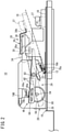
FIG. 2 is a side view showing the damper opening/closing device according to the present embodiment as viewed from the direction of the arrow II inFIG. 1 ; -
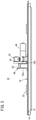
FIG. 3 is a front view showing the damper opening/closing device according to the present embodiment as viewed from the direction of the arrow III inFIG. 1 ; -
FIG. 4 is a plan view showing a return mechanism and a retention mechanism as viewed from above; -
FIG. 5A is a front view showing an assembly of a cam plate and a crank plate; -
FIG. 5B is a cross-sectional view taken along line VB-VB inFIG. 5A ; -
FIG. 6 is a wiring diagram showing a part of a circuit system including a rotation control unit; and -
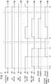
FIG. 7 is a time chart showing operations of the damper opening/closing device according to the present embodiment. - Hereinafter, an exemplary embodiment of a damper opening/closing device according to the present invention will be described with reference to
FIGS. 1 to 7 . - As shown in
FIGS. 1 to 3 , a damper opening/closing device 10 according to the present embodiment is installed, for example, in anopening 12 such as an air supply port installed on the floor surface of a container or the like. - The damper opening/
closing device 10 includes abase platform 16 having aframe portion 14 mounted so as to surround theopening 12 within the floor surface, an opening/closing lid 18 that is installed to be capable of rotating with respect to thebase platform 16 and that opens and closes theopening 12, aretention mechanism 20 fixed to thebase platform 16, and areturn mechanism 24. - In addition to the above-described
frame portion 14, thebase platform 16 integrally includes apedestal 26, which is installed adjacent to one side of theframe portion 14. - The opening/
closing lid 18 is formed, for example, by a metal plate, and with a sufficient size so as to close theopening 12. In the example shown inFIG. 1 , since theopening 12 has a rectangular shape when viewed from above, the opening/closing lid 18 is formed in a rectangular shape in the same manner as theopening 12. Of course, depending on the shape of theopening 12, the shape of the opening/closing lid 18 may be a circular shape, an elliptical shape, a track shape, a polygonal shape, or the like. Moreover, such a track shape is a shape that is made up from two opposing semicircular portions, and two parallel straight line portions connecting the two semicircular portions. Further, a lockedmetal fixture 27, which is locked and fixed by theretention mechanism 20, is provided on an upper part of the opening/closing lid 18. - The
retention mechanism 20 retains the opening/closing lid 18 and places the opening 12 in the open state during a period in which supply of electrical power from an external power source or the like is being carried out, and releases retention of the opening/closing lid 18 when the supply of electrical power is stopped. - More specifically, as shown in
FIGS. 2 and4 , theretention mechanism 20 includes amotor base 28, and anelectromagnetic chuck 30 fixed to a distal end portion of themotor base 28. Themotor base 28 includes, on thebase platform 16, two metal plates (afirst metal plate 32A and asecond metal plate 32B: seeFIG. 4 ) installed in an L-shape when viewed from above. Both thefirst metal plate 32A and thesecond metal plate 32B are installed so that plate surfaces thereof extend in a vertical direction, in other words, so that the plate surfaces are oriented along a horizontal direction. Thefirst metal plate 32A is installed on thebase platform 16, and thesecond metal plate 32B is installed from thebase platform 16 to a location above the opening/closing lid 18. However, thesecond metal plate 32B is not fixed to the opening/closing lid 18. Further, a part of a lower portion of thesecond metal plate 32B is removed or cut off, so as not to interfere with an opening operation of the opening/closing lid 18. - In addition, a
mounting metal fixture 34 used for mounting theelectromagnetic chuck 30 and having a U-shaped cross section is attached to the plate surface of thesecond metal plate 32B, and theelectromagnetic chuck 30 is attached to a distal end portion of themounting metal fixture 34. Further, aretaining metal fixture 36 is rotatably attached by asupport shaft 38 to the mountingmetal fixture 34. Theretaining metal fixture 36 includes an attractedsite 36a facing an attracting surface of theelectromagnetic chuck 30, and alocking site 36b having, for example, an L-shaped cross section, and integrally provided on a distal end of the attractedsite 36a. - In addition, as shown by the two-dot-dashed line in
FIG. 2 , in a state in which the mountingmetal fixture 34 is retained (attracted) by theelectromagnetic chuck 30, a portion of the lockedmetal fixture 27 provided on the upper part of the opening/closing lid 18 is locked onto thelocking site 36b, whereby the opening/closing lid 18 is retained in the open state. When the supply of electrical power is stopped, and retention (attraction) by theelectromagnetic chuck 30 is released, theretaining metal fixture 36 is rotated about thesupport shaft 38 by the weight of the opening/closing lid 18, whereby the lockedmetal fixture 27 of the opening/closing lid 18 is disengaged from theretaining metal fixture 36. As a result, the opening/closing lid 18 rotates (falls) abouthinges 22, and theopening 12 is placed in a closed state (refer to the solid line inFIG. 2 ). - The
hinges 22 are attached between the opening/closing lid 18 and portions of theframe portion 14 of thebase platform 16 where thepedestal 26 is provided. Consequently, at first, the opening/closing lid 18 is retained by theretention mechanism 20 in a state of being oriented obliquely upward with thehinges 22 serving as a fulcrum or point of rotation. When the retention by theretention mechanism 20 is released, the opening/closing lid 18 falls downward due to its own weight, and at this time, the opening/closing lid 18 rotates downward about thehinges 22, and closes theopening 12. Moreover, in the example shown inFIG. 1 , a case is shown in which thehinges 22 are attached on both left and right sides of a long side of the opening/closing lid 18 that are adjacent to a portion where thepedestal 26 of theframe portion 14 is provided. Of course, the positions where thehinges 22 are attached and the number of thehinges 22 may be appropriately set in accordance with the shape of the opening/closing lid 18. - As shown in
FIG. 2 , when the supply of electrical power is restarted, thereturn mechanism 24 lifts the opening/closing lid 18 upward, and causes the opening/closing lid 18 to be returned to the state of being retained by theretention mechanism 20. Further, during the supply of electrical power, even if the retention by theelectromagnetic chuck 30 is released and the opening/closing lid 18 is placed in the closed state, the opening/closing lid 18 is lifted upward, and the opening/closing lid 18 is returned to the state of being retained by theretention mechanism 20. - More specifically, as shown in
FIGS. 1 and3 , thereturn mechanism 24 includes amotor 40, anarm 42 that rotates the opening/closing lid 18 upward accompanying rotation of themotor 40, arotation control unit 44 that controls rotational driving of the motor 40 (seeFIG. 6 ), and atransmission mechanism 46 that transmits a rotational force of themotor 40 to the arm 42 (seeFIGS. 2 ,5A, and 5B ) . - Further, as shown in
FIG. 1 , thereturn mechanism 24 includes ahandle 48 provided on an upper surface of the opening/closing lid 18, and ahinge pin 50 provided on thehandle 48. Thehandle 48 is formed by, for example, opposing two L-shaped metal plates FIG. 3 ) that extend from a side on which thehinges 22 are attached toward a side opposing to that side. Thehinge pin 50 is connected between the twometal plates - The
motor 40 is installed on thepedestal 26 in a manner so that an output shaft 54 (rotary shaft) of themotor 40 penetrates through thesecond metal plate 32B (seeFIG. 5B ) of themotor base 28. - As shown in
FIGS. 5A and 5B , thetransmission mechanism 46 includes acam plate 56 attached to theoutput shaft 54 of themotor 40 that penetrates through thesecond metal plate 32B. Thecam plate 56 includes acam surface 56a formed by an outwardly bulging portion of a disk-shaped peripheral surface thereof. - As shown in
FIG. 6 , therotation control unit 44 includes a damperinternal circuit 64 connected between apower supply line 60 and aground line 62, and afirst switch 66A and asecond switch 66B connected respectively between thepower supply line 60 and the damperinternal circuit 64. Thefirst switch 66A includes, for example, a normally opentype make contact 68a (a-contact), and is turned on when supply of electrical power from the external power source or the like is started. Consequently, electrical power is supplied to the damperinternal circuit 64 through thepower supply line 60. On the other hand, thesecond switch 66B includes, for example, a normally closedtype break contact 68b (b-contact), and normally, electrical power from the external power source or the like is supplied to the damperinternal circuit 64 through thepower supply line 60. - The damper
internal circuit 64 includes, for example, four contacts (first throughfourth contacts 70a to 70d). Thefirst switch 66A is connected between thepower supply line 60 and thefirst contact 70a, and thesecond switch 66B is connected between thepower supply line 60 and thesecond contact 70b. Thethird contact 70c and thefourth contact 70d are connected to theground line 62. - Further, the damper
internal circuit 64 includes themotor 40 connected between thefirst contact 70a and thethird contact 70c, afirst limit switch 74A and asecond limit switch 74B connected in parallel between thefirst contact 70a and themotor 40, and theelectromagnetic chuck 30 connected between thesecond contact 70b and thefourth contact 70d. - The
first limit switch 74A includes, for example, a normally closed typefirst break contact 78a, and thesecond limit switch 74B includes, for example, a normally closed typesecond break contact 78b. Accordingly, as can be understood fromFIG. 6 , themotor 40 is rotationally driven when at least one of thefirst break contact 78a and thesecond break contact 78b is placed in an on state. - Further, as shown in
FIG. 2 , thefirst limit switch 74A is attached, for example, between the mountingmetal fixture 34 and the opening/closinglid 18. Preferably, thefirst limit switch 74A is attached at a position where thefirst break contact 78a of thefirst limit switch 74A becomes placed in the off state by the opening/closinglid 18, at a stage when the opening/closinglid 18 transitions to the open state. Of course, thefirst limit switch 74A may be attached at a position where thefirst break contact 78a thereof becomes placed in the off state, at a stage when the opening/closinglid 18 is fully opened. - The
second limit switch 74B, for example, is attached to a surface of thesecond metal plate 32B of themotor base 28, the surface facing thearm 42, above thecam plate 56. Preferably, thesecond limit switch 74B is attached at a position where thesecond break contact 78b is placed in the off state by thecam surface 56a of thecam plate 56. In an initial state, specifically, in a state in which thearm 42 is in an initial position, as shown inFIG. 2 , apin 80a of acrank plate 80 is in an upper limit position, and thecam surface 56a of thecam plate 56 presses thesecond break contact 78b of thesecond limit switch 74B, whereby thesecond break contact 78b becomes placed in the off state. Moreover, the upper limit position refers to a position from which thepin 80a is incapable of being moved upward any further. - Accordingly, when the
cam plate 56 is rotated due to rotation of themotor 40, thesecond break contact 78b becomes placed in the off state over a period of time during which thecam surface 56a presses thesecond break contact 78b of thesecond limit switch 74B. When thecam surface 56a separates away from thesecond break contact 78b, thesecond break contact 78b is placed in the on state. - As shown in
FIGS. 2 ,5A, and 5B , thetransmission mechanism 46 includes thecrank plate 80, which is disposed on an outer side of thecam plate 56 and is attached to theoutput shaft 54 of themotor 40. Thecrank plate 80 is provided with, on the surface thereof that is opposite to thecam plate 56 side and at an eccentric position, thepin 80a which projects outwardly. - As shown in
FIGS. 1 and2 , thearm 42 is constituted by an elongate metal fixture having an L-shaped cross section and extending from thebase platform 16 side toward the opening/closinglid 18 side. As shown inFIG. 2 , thearm 42 includes arotary shaft 82 provided in a central portion thereof, and anelongate hole 84 which is provided on thebase platform 16 side, and through which thepin 80a of thecrank plate 80 is inserted. Theelongate hole 84 is formed so that a major axis thereof lies along the longitudinal direction of thearm 42. - When the
crank plate 80 is rotated in one direction (in a counterclockwise direction when viewed from theoutput shaft 54 of the motor 40) by rotational driving of themotor 40, thepin 80a of thecrank plate 80 slides along theelongate hole 84 of thearm 42 while rotating. Consequently, thearm 42 rotates in a counterclockwise direction about therotary shaft 82, and thehinge pin 50 of thehandle 48 is hooked on adistal end portion 42a (seeFIG. 1 ) on the opening/closinglid 18 side, and is lifted upward. As a result, the opening/closinglid 18 is rotated upward about thehinges 22, and is retained in the open state by theelectromagnetic chuck 30. - In this instance, operations of the damper opening/
closing device 10 according to the present embodiment will be described with reference to the time chart shown inFIG. 7 . - First, at time t1, when supply of electrical power to the
power supply line 60 from the external power source or the like is carried out, thefirst switch 66A is placed in the on state, and electrical power is supplied to themotor 40, together with electrical power being supplied to theelectromagnetic chuck 30 via thesecond switch 66B. For example, as shown inFIG. 2 , by electrical power being supplied to the motor 40 (seeFIG. 3 ), thecam plate 56 and thecrank plate 80 are rotated in a counterclockwise direction, and along therewith, thecam surface 56a of thecam plate 56 separates away from thesecond break contact 78b of thesecond limit switch 74B, and thesecond limit switch 74B becomes placed in the on state (at time t2). Further, thearm 42 is also rotated in a counterclockwise direction about therotary shaft 82, and gradually lifts the opening/closinglid 18 upward (refer to the two-dot-dashed line inFIG. 2 ). Consequently, the opening/closinglid 18 rotates upward about the hinges 22. - In addition, accompanying rotation of the
cam plate 56 and thecrank plate 80, thepin 80a of thecrank plate 80 arrives, for example, at a lower limit position, or alternatively in the vicinity thereof, and at a stage (for example, at time t3) at which the opening/closinglid 18 is fully opened, the opening/closinglid 18 is retained by theelectromagnetic chuck 30. Moreover, the lower limit position refers to a position from which thepin 80a is incapable of being moved downward any further. Further, at this time, in accordance with thefirst break contact 78a being pressed by the opening/closinglid 18, thefirst limit switch 74A becomes placed in the off state. At this stage, since electrical power is being supplied to themotor 40 via thesecond limit switch 74B, thecam plate 56 and thecrank plate 80 continue to rotate in the counterclockwise direction. - Thereafter, accompanying rotation of the
cam plate 56 and thecrank plate 80, thecam surface 56a of thecam plate 56 presses thesecond break contact 78b of thesecond limit switch 74B, whereby thesecond break contact 78b becomes placed in the off state (at time t4), and supply of electrical power to themotor 40 is stopped. At this time, since thepin 80a arrives at the upper limit position, or alternatively in the vicinity thereof and thecam plate 56 and thecrank plate 80 stop rotating, thearm 42 is returned to the initial state (refer to the solid line inFIG. 2 ). - If the retention of the opening/closing
lid 18 by theelectromagnetic chuck 30 is released and the opening/closinglid 18 becomes placed in the closed state due to its own weight, since thefirst break contact 78a of thefirst limit switch 74A is placed in the on state (at time t5), rotational driving of themotor 40 is started (restarted) again, the operations at the times t2 to t4 are repeated, and the opening/closinglid 18 is returned to the open state. Such a returning operation is based on priority being given to driving of the opening/closinglid 18 to be opened, because basically, it is necessary for the opening/closinglid 18 to be maintained open (in a state of supplying air) at all times. - In contrast thereto, at the time of an emergency (at a time when a combustible gas is detected or the like), the opening/closing
lid 18 is placed in the closed state by stopping the supply of electrical power to thepower supply line 60. More specifically, for example, at time t6, in the case that a combustible gas is detected, the supply of electrical power to thepower supply line 60 from the external power source or the like is stopped. Consequently, the supply of electrical power to theelectromagnetic chuck 30 and themotor 40 is stopped, and the opening/closinglid 18 becomes placed in the closed state. - In this manner, in the damper opening/
closing device 10 according to the present embodiment, the opening/closinglid 18 is retained by theretention mechanism 20 in a state of being oriented obliquely upward with thehinges 22 serving as a fulcrum or point of rotation, whereby theopening 12 can be placed in the open state. Even if the retention by theelectromagnetic chuck 30 is released and the opening/closinglid 18 is placed in the closed state, the opening/closinglid 18 is driven by thereturn mechanism 24, and the opening/closinglid 18 can be returned to the state of being retained by theretention mechanism 20. In particular, when the opening/closinglid 18 is retained in the open state by theretention mechanism 20, thearm 42 is returned to the initial position. Therefore, the opening/closinglid 18 can be smoothly returned to the open state by thereturn mechanism 24. - On the other hand, at the time of an emergency or the like, when the supply of electrical power to the
retention mechanism 20 is stopped, the retention by theretention mechanism 20 is released, and the opening/closinglid 18 falls downward due to its own weight. At this time, the opening/closinglid 18 rotates downward about thehinges 22, and closes theopening 12. More specifically, theopening 12 can be placed in the closed state. Even if the supply of electrical power from the external power source is cut off, theopening 12 can be closed without using an electrical means such as an electrical power storage means or the like, and consumption of electrical power (standby power or the like) can be reduced. - In the case that the supply of electrical power from the external power source is restarted, the opening/closing
lid 18 is retained again by theretention mechanism 20 in a state of being oriented obliquely upward with thehinges 22 serving as a fulcrum or point of rotation, whereby theopening 12 can be placed in the open state. - Further, according to the present embodiment, there are included the
crank plate 80 which is rotated by driving of themotor 40, and rotates thearm 42 in a direction to open the opening/closinglid 18, and thecam plate 56 which is rotated together with thecrank plate 80 by driving of themotor 40. Thecam plate 56 includes thecam surface 56a that places thesecond break contact 78b in an off state based on thearm 42 being returned to the initial position. - By rotating the
crank plate 80 together with thecam plate 56 by themotor 40, it is possible to perform, by thesingle motor 40, the operation of rotating thearm 42 in the direction to open the opening/closinglid 18 by thecrank plate 80, and the operation of placing thesecond break contact 78b in the off state by thecam surface 56a of thecam plate 56 based on thearm 42 being returned to its initial position, and it is possible to effectively simplify the structure and reduce the number of component parts. - The above-described embodiment can be summarized in the following manner.
- [1] The damper opening/
closing device 10 is a damper opening/closing device installed in theopening 12 used for air conditioning, and comprises the opening/closinglid 18, theretention mechanism 20 that retains the opening/closinglid 18 and places theopening 12 in the open state during a period in which supply of electrical power is being carried out, and releases retention of the opening/closinglid 18 and places theopening 12 in a closed state when the supply of electrical power is stopped, and thereturn mechanism 24 that returns the opening/closinglid 18 to the state of being retained by theretention mechanism 20, in the case that the opening/closinglid 18 is in the closed state during the period in which supply of electrical power is being carried out.
In accordance with these features, initially, during the period in which electrical power is being supplied, theretention mechanism 20 retains the opening/closinglid 18 and places theopening 12 in the open state. When the supply of electrical power is stopped, theretention mechanism 20 releases the retention of the opening/closinglid 18, and thereby places theopening 12 in the closed state. In this manner, even if the supply of electrical power from the external power source is cut off, theopening 12 can be closed without using an electrical means such as an electrical power storage means or the like, and consumption of electrical power (standby power or the like) can be reduced. Additionally, even if the retention by theretention mechanism 20 is released and the opening/closinglid 18 is placed in the closed state during the period in which supply of electrical power is being carried out, it is possible for the opening/closinglid 18 to be returned to the state of being retained by theretention mechanism 20, by thereturn mechanism 24. - [2] In the present embodiment, the
retention mechanism 20 may be theelectromagnetic chuck 30 that electromagnetically retains the opening/closinglid 18. The opening/closinglid 18 can be retained in the open state by supplying electrical power thereto. - [3] In the present invention, movement of the opening/closing
lid 18 when retention of the opening/closinglid 18 by theretention mechanism 20 is released takes place due to the weight of the opening/closinglid 18. In accordance with this feature, even if the supply of electrical power from the external power source is cut off, the air supply port or the like can be closed by the opening/closinglid 18 without using an electrical power storage means or the like. - [4] In the present embodiment, the
return mechanism 24 includes thefirst contact 70a and thesecond contact 70b, themotor 40 which is rotationally driven based on at least one of thefirst contact 70a and thesecond contact 70b being placed in an on state, and thearm 42 that rotates in a direction to open the opening/closinglid 18 from the initial position as themotor 40 is rotationally driven. Thefirst contact 70a is placed in the off state based on the open state of the opening/closinglid 18, and thesecond contact 70b is placed in the off state based on thearm 42 being returned to the initial position. In accordance with these features, when the opening/closinglid 18 is retained in the open state by theretention mechanism 20, thearm 42 is returned to the initial position. Therefore, the opening/closinglid 18 can be smoothly returned to the open state by thereturn mechanism 24. - [5] In the present embodiment, the open state of the opening/closing
lid 18 is a state in which the opening/closinglid 18 is retained by theretention mechanism 20, and thesecond contact 70b is placed in the off state based on thearm 42 being returned to the initial position, after thefirst contact 70a has been placed in the off state. - [6] In the present embodiment, there are further included the
crank plate 80 which is rotated by driving of themotor 40, and rotates thearm 42 in the direction to open the opening/closinglid 18, and thecam plate 56 that is rotated together with thecrank plate 80 by driving of themotor 40, and thecam plate 56 includes thecam surface 56a that places thesecond contact 70b in the off state based on thearm 42 being returned to the initial position. - The
crank plate 80 and thecam plate 56 are rotated together by themotor 40. Consequently, it is possible to perform, by a single motor, the operation of rotating thearm 42 in the direction to open the opening/closinglid 18 by thecrank plate 80, and the operation of placing thesecond contact 70b in the off state by thecam surface 56a of thecam plate 56 based on thearm 42 being returned to its initial position, and it is possible to effectively simplify the structure and reduce the number of component parts. - Moreover, the damper opening/closing device according to the present invention is not limited to the above-described embodiment, and it is a matter of course that various configurations could be adopted therein without departing from the essence and gist of the present invention.
Claims (6)
- A damper opening/closing device (10) installed in an opening (12) used for air conditioning, the damper opening/closing device (10) comprising:an opening/closing lid (18);a retention mechanism (20) configured to retain the opening/closing lid (18) and place the opening (12) in an open state during a period in which supply of electrical power is being carried out, and to release retention of the opening/closing lid (18) and place the opening (12) in a closed state when the supply of electrical power is stopped; anda return mechanism (24) configured to return the opening/closing lid (18) to the state of being retained by the retention mechanism (20), in a case that the opening/closing lid (18) is in a closed state during the period in which the supply of electrical power is being carried out.
- The damper opening/closing device (10) according to claim 1, wherein the retention mechanism (20) includes an electromagnetic chuck (30) configured to electromagnetically retain the opening/closing lid (18).
- The damper opening/closing device (10) according to claim 1 or 2, wherein movement of the opening/closing lid (18) when retention of the opening/closing lid (18) by the retention mechanism (20) is released takes place due to a weight of the opening/closing lid (18).
- The damper opening/closing device (10) according to any one of claims 1 to 3, whereinthe return mechanism (24) includes:a first contact (70a) and a second contact (70b);a motor (40) configured to be rotationally driven based on at least one of the first contact (70a) and the second contact (70b) being placed in an on state; andan arm (42) configured to rotate in a direction to open the opening/closing lid (18) from an initial position as the motor (40) is rotationally driven,the first contact (70a) is placed in an off state based on an open state of the opening/closing lid (18), andthe second contact (70b) is placed in an off state based on the arm (42) being returned to the initial position.
- The damper opening/closing device (10) according to claim 4, whereinthe open state of the opening/closing lid (18) is a state in which the opening/closing lid (18) is retained by the retention mechanism (20), andthe second contact (70b) is placed in the off state based on the arm (42) being returned to the initial position, after the first contact (70a) has been placed in the off state.
- The damper opening/closing device (10) according to claim 4 or 5, further comprising:a crank plate (80) configured to be rotated by driving of the motor (40), and to rotate the arm (42) in the direction to open the opening/closing lid (18); anda cam plate (56) configured to be rotated together with the crank plate (80) by driving of the motor (40), whereinthe cam plate (56) includes a cam surface (56a) configured to place the second contact (70b) in the off state based on the arm (42) being returned to the initial position.
Applications Claiming Priority (2)
| Application Number | Priority Date | Filing Date | Title |
|---|---|---|---|
| JP2019047246 | 2019-03-14 | ||
| PCT/JP2020/009162 WO2020184333A1 (en) | 2019-03-14 | 2020-03-04 | Damper opening/closing device |
Publications (3)
| Publication Number | Publication Date |
|---|---|
| EP3940309A1 true EP3940309A1 (en) | 2022-01-19 |
| EP3940309A4 EP3940309A4 (en) | 2022-12-07 |
| EP3940309B1 EP3940309B1 (en) | 2025-07-30 |
Family
ID=72426227
Family Applications (1)
| Application Number | Title | Priority Date | Filing Date |
|---|---|---|---|
| EP20769422.5A Active EP3940309B1 (en) | 2019-03-14 | 2020-03-04 | Damper opening/closing device |
Country Status (3)
| Country | Link |
|---|---|
| EP (1) | EP3940309B1 (en) |
| JP (1) | JP7176093B2 (en) |
| WO (1) | WO2020184333A1 (en) |
Families Citing this family (2)
| Publication number | Priority date | Publication date | Assignee | Title |
|---|---|---|---|---|
| US12466237B2 (en) * | 2022-08-17 | 2025-11-11 | B/E Aerospace, Inc. | Systems and methods for mitigating leaking flammable refrigerants |
| CN120942713B (en) * | 2025-10-16 | 2025-12-23 | 山西建投矿建集团有限公司 | Intelligent mining large-batch diversified sensor auxiliary installation equipment |
Family Cites Families (11)
| Publication number | Priority date | Publication date | Assignee | Title |
|---|---|---|---|---|
| US4333489A (en) * | 1978-09-11 | 1982-06-08 | Actionair Equipment Limited | Spring-motor dual-functioning mechanism |
| JPS5848513Y2 (en) * | 1980-06-09 | 1983-11-05 | 株式会社 熊平製作所 | Duct damper opening/closing device |
| JPS5941473Y2 (en) * | 1980-06-09 | 1984-11-30 | 株式会社東芝 | shutter device |
| JPS598730B2 (en) * | 1980-12-29 | 1984-02-27 | 東京電機産業株式会社 | Damper opening/closing device |
| JPH0210050A (en) * | 1988-06-29 | 1990-01-12 | Yukihiro Obata | Drive device for damper for ventilation, valve body opening closing device thereof, and electrid motor thereof |
| JPH05277200A (en) * | 1992-04-16 | 1993-10-26 | Kuken Denki Kk | Fire damper opening / closing device |
| US5533929A (en) * | 1993-12-29 | 1996-07-09 | Attridge, Jr.; Russell G. | Remotely trippable and resettable damper |
| JP3491594B2 (en) * | 2000-02-16 | 2004-01-26 | 株式会社北村製作所 | Outdoor hood with damper function |
| JP2006187524A (en) | 2005-01-07 | 2006-07-20 | Dairitsu:Kk | Damper opening and closing device |
| JP2008039313A (en) * | 2006-08-08 | 2008-02-21 | Matsushita Electric Ind Co Ltd | Ventilation equipment |
| JP5535369B1 (en) * | 2013-04-30 | 2014-07-02 | 株式会社新来島どっく | Hold fan duct structure of a car carrier |
-
2020
- 2020-03-04 WO PCT/JP2020/009162 patent/WO2020184333A1/en not_active Ceased
- 2020-03-04 JP JP2021504969A patent/JP7176093B2/en active Active
- 2020-03-04 EP EP20769422.5A patent/EP3940309B1/en active Active
Also Published As
| Publication number | Publication date |
|---|---|
| JP7176093B2 (en) | 2022-11-21 |
| EP3940309B1 (en) | 2025-07-30 |
| JPWO2020184333A1 (en) | 2021-10-14 |
| EP3940309A4 (en) | 2022-12-07 |
| WO2020184333A1 (en) | 2020-09-17 |
Similar Documents
| Publication | Publication Date | Title |
|---|---|---|
| KR100940728B1 (en) | Attachment Structure of Service Plug | |
| EP3940309B1 (en) | Damper opening/closing device | |
| WO2020008768A1 (en) | Driving machine | |
| ITTO20110092A1 (en) | POWER SOCKET GROUP FOR RECHARGING ELECTRIC VEHICLE BATTERIES | |
| EP3722129B1 (en) | Vehicle comprising a battery pack | |
| CN105593446B (en) | The electrically operated motor vehicle door lock of energy | |
| JP2022502147A (en) | Door lock and control circuit for door lock | |
| US10577841B2 (en) | Electric motor vehicle lock having a spring accumulator | |
| US10094148B2 (en) | Closing device for a motor-vehicle hood, and method | |
| CN100511630C (en) | Load port and load port control method | |
| EP4180676A1 (en) | An unmanned aerial vehicle (uav) | |
| KR102485346B1 (en) | High voltage connector | |
| KR100931014B1 (en) | Door lock device of freight elevator | |
| JP6237203B2 (en) | Vehicle charging unit structure | |
| KR20020082189A (en) | Magnetic adsorber for conveying iron material | |
| CN204310658U (en) | A latch-up protection device is protected for elevator | |
| CN115579254B (en) | Dual-power change-over switch | |
| JP2012234775A (en) | Charge connector | |
| CN112349538A (en) | Operating mechanism of vacuum circuit breaker | |
| CN201933889U (en) | side open car door lock | |
| CN113816117B (en) | Manual unloading system and its safety mechanism | |
| JP2008060437A (en) | Mounting machine safety device | |
| JP2006187524A (en) | Damper opening and closing device | |
| CN211321762U (en) | Toilet seat electric cabinet and toilet seat | |
| JP2008282568A (en) | Programmable controller connecting device |
Legal Events
| Date | Code | Title | Description |
|---|---|---|---|
| STAA | Information on the status of an ep patent application or granted ep patent |
Free format text: STATUS: THE INTERNATIONAL PUBLICATION HAS BEEN MADE |
|
| PUAI | Public reference made under article 153(3) epc to a published international application that has entered the european phase |
Free format text: ORIGINAL CODE: 0009012 |
|
| STAA | Information on the status of an ep patent application or granted ep patent |
Free format text: STATUS: REQUEST FOR EXAMINATION WAS MADE |
|
| 17P | Request for examination filed |
Effective date: 20210910 |
|
| AK | Designated contracting states |
Kind code of ref document: A1 Designated state(s): AL AT BE BG CH CY CZ DE DK EE ES FI FR GB GR HR HU IE IS IT LI LT LU LV MC MK MT NL NO PL PT RO RS SE SI SK SM TR |
|
| DAV | Request for validation of the european patent (deleted) | ||
| DAX | Request for extension of the european patent (deleted) | ||
| RIN1 | Information on inventor provided before grant (corrected) |
Inventor name: FUKUHARA, MOTOHIRO |
|
| A4 | Supplementary search report drawn up and despatched |
Effective date: 20221107 |
|
| RIC1 | Information provided on ipc code assigned before grant |
Ipc: F25D 17/04 20060101ALI20221031BHEP Ipc: B65D 88/74 20060101ALI20221031BHEP Ipc: F24F 11/32 20180101ALI20221031BHEP Ipc: A62C 2/06 20060101ALI20221031BHEP Ipc: F24F 11/36 20180101ALI20221031BHEP Ipc: F24F 11/89 20180101ALI20221031BHEP Ipc: F24F 11/72 20180101ALI20221031BHEP Ipc: F24F 13/14 20060101ALI20221031BHEP Ipc: F24F 13/10 20060101AFI20221031BHEP |
|
| GRAP | Despatch of communication of intention to grant a patent |
Free format text: ORIGINAL CODE: EPIDOSNIGR1 |
|
| STAA | Information on the status of an ep patent application or granted ep patent |
Free format text: STATUS: GRANT OF PATENT IS INTENDED |
|
| RIC1 | Information provided on ipc code assigned before grant |
Ipc: A62C 2/24 20060101ALI20250227BHEP Ipc: F24F 13/14 20060101ALI20250227BHEP Ipc: F24F 11/72 20180101ALI20250227BHEP Ipc: F24F 11/89 20180101ALI20250227BHEP Ipc: F24F 11/36 20180101ALI20250227BHEP Ipc: A62C 2/06 20060101ALI20250227BHEP Ipc: F24F 11/32 20180101ALI20250227BHEP Ipc: B65D 88/74 20060101ALI20250227BHEP Ipc: F25D 17/04 20060101ALI20250227BHEP Ipc: F24F 13/10 20060101AFI20250227BHEP |
|
| INTG | Intention to grant announced |
Effective date: 20250312 |
|
| GRAS | Grant fee paid |
Free format text: ORIGINAL CODE: EPIDOSNIGR3 |
|
| GRAA | (expected) grant |
Free format text: ORIGINAL CODE: 0009210 |
|
| STAA | Information on the status of an ep patent application or granted ep patent |
Free format text: STATUS: THE PATENT HAS BEEN GRANTED |
|
| AK | Designated contracting states |
Kind code of ref document: B1 Designated state(s): AL AT BE BG CH CY CZ DE DK EE ES FI FR GB GR HR HU IE IS IT LI LT LU LV MC MK MT NL NO PL PT RO RS SE SI SK SM TR |
|
| REG | Reference to a national code |
Ref country code: GB Ref legal event code: FG4D |
|
| REG | Reference to a national code |
Ref country code: CH Ref legal event code: EP |
|
| REG | Reference to a national code |
Ref country code: DE Ref legal event code: R096 Ref document number: 602020055499 Country of ref document: DE |
|
| REG | Reference to a national code |
Ref country code: IE Ref legal event code: FG4D |
|
| REG | Reference to a national code |
Ref country code: NL Ref legal event code: MP Effective date: 20250730 |
|
| REG | Reference to a national code |
Ref country code: AT Ref legal event code: MK05 Ref document number: 1819296 Country of ref document: AT Kind code of ref document: T Effective date: 20250730 |
|
| PG25 | Lapsed in a contracting state [announced via postgrant information from national office to epo] |
Ref country code: PT Free format text: LAPSE BECAUSE OF FAILURE TO SUBMIT A TRANSLATION OF THE DESCRIPTION OR TO PAY THE FEE WITHIN THE PRESCRIBED TIME-LIMIT Effective date: 20251202 |
|
| PG25 | Lapsed in a contracting state [announced via postgrant information from national office to epo] |
Ref country code: IS Free format text: LAPSE BECAUSE OF FAILURE TO SUBMIT A TRANSLATION OF THE DESCRIPTION OR TO PAY THE FEE WITHIN THE PRESCRIBED TIME-LIMIT Effective date: 20251130 |
|
| PG25 | Lapsed in a contracting state [announced via postgrant information from national office to epo] |
Ref country code: NO Free format text: LAPSE BECAUSE OF FAILURE TO SUBMIT A TRANSLATION OF THE DESCRIPTION OR TO PAY THE FEE WITHIN THE PRESCRIBED TIME-LIMIT Effective date: 20251030 |
|
| REG | Reference to a national code |
Ref country code: LT Ref legal event code: MG9D |
|
| PG25 | Lapsed in a contracting state [announced via postgrant information from national office to epo] |
Ref country code: AT Free format text: LAPSE BECAUSE OF FAILURE TO SUBMIT A TRANSLATION OF THE DESCRIPTION OR TO PAY THE FEE WITHIN THE PRESCRIBED TIME-LIMIT Effective date: 20250730 |
|
| PG25 | Lapsed in a contracting state [announced via postgrant information from national office to epo] |
Ref country code: FI Free format text: LAPSE BECAUSE OF FAILURE TO SUBMIT A TRANSLATION OF THE DESCRIPTION OR TO PAY THE FEE WITHIN THE PRESCRIBED TIME-LIMIT Effective date: 20250730 |
|
| PG25 | Lapsed in a contracting state [announced via postgrant information from national office to epo] |
Ref country code: NL Free format text: LAPSE BECAUSE OF FAILURE TO SUBMIT A TRANSLATION OF THE DESCRIPTION OR TO PAY THE FEE WITHIN THE PRESCRIBED TIME-LIMIT Effective date: 20250730 Ref country code: HR Free format text: LAPSE BECAUSE OF FAILURE TO SUBMIT A TRANSLATION OF THE DESCRIPTION OR TO PAY THE FEE WITHIN THE PRESCRIBED TIME-LIMIT Effective date: 20250730 |
|
| PG25 | Lapsed in a contracting state [announced via postgrant information from national office to epo] |
Ref country code: GR Free format text: LAPSE BECAUSE OF FAILURE TO SUBMIT A TRANSLATION OF THE DESCRIPTION OR TO PAY THE FEE WITHIN THE PRESCRIBED TIME-LIMIT Effective date: 20251031 |
|
| PG25 | Lapsed in a contracting state [announced via postgrant information from national office to epo] |
Ref country code: SE Free format text: LAPSE BECAUSE OF FAILURE TO SUBMIT A TRANSLATION OF THE DESCRIPTION OR TO PAY THE FEE WITHIN THE PRESCRIBED TIME-LIMIT Effective date: 20250730 |
|
| PG25 | Lapsed in a contracting state [announced via postgrant information from national office to epo] |
Ref country code: LV Free format text: LAPSE BECAUSE OF FAILURE TO SUBMIT A TRANSLATION OF THE DESCRIPTION OR TO PAY THE FEE WITHIN THE PRESCRIBED TIME-LIMIT Effective date: 20250730 |
|
| PG25 | Lapsed in a contracting state [announced via postgrant information from national office to epo] |
Ref country code: PL Free format text: LAPSE BECAUSE OF FAILURE TO SUBMIT A TRANSLATION OF THE DESCRIPTION OR TO PAY THE FEE WITHIN THE PRESCRIBED TIME-LIMIT Effective date: 20250730 Ref country code: BG Free format text: LAPSE BECAUSE OF FAILURE TO SUBMIT A TRANSLATION OF THE DESCRIPTION OR TO PAY THE FEE WITHIN THE PRESCRIBED TIME-LIMIT Effective date: 20250730 |
|
| PG25 | Lapsed in a contracting state [announced via postgrant information from national office to epo] |
Ref country code: RS Free format text: LAPSE BECAUSE OF FAILURE TO SUBMIT A TRANSLATION OF THE DESCRIPTION OR TO PAY THE FEE WITHIN THE PRESCRIBED TIME-LIMIT Effective date: 20251030 |
|
| PG25 | Lapsed in a contracting state [announced via postgrant information from national office to epo] |
Ref country code: ES Free format text: LAPSE BECAUSE OF FAILURE TO SUBMIT A TRANSLATION OF THE DESCRIPTION OR TO PAY THE FEE WITHIN THE PRESCRIBED TIME-LIMIT Effective date: 20250730 |
|
| PG25 | Lapsed in a contracting state [announced via postgrant information from national office to epo] |
Ref country code: SM Free format text: LAPSE BECAUSE OF FAILURE TO SUBMIT A TRANSLATION OF THE DESCRIPTION OR TO PAY THE FEE WITHIN THE PRESCRIBED TIME-LIMIT Effective date: 20250730 |
|
| PGFP | Annual fee paid to national office [announced via postgrant information from national office to epo] |
Ref country code: GB Payment date: 20260202 Year of fee payment: 7 |
|
| PG25 | Lapsed in a contracting state [announced via postgrant information from national office to epo] |
Ref country code: DK Free format text: LAPSE BECAUSE OF FAILURE TO SUBMIT A TRANSLATION OF THE DESCRIPTION OR TO PAY THE FEE WITHIN THE PRESCRIBED TIME-LIMIT Effective date: 20250730 |
|
| PGFP | Annual fee paid to national office [announced via postgrant information from national office to epo] |
Ref country code: DE Payment date: 20260128 Year of fee payment: 7 |
|
| PG25 | Lapsed in a contracting state [announced via postgrant information from national office to epo] |
Ref country code: IT Free format text: LAPSE BECAUSE OF FAILURE TO SUBMIT A TRANSLATION OF THE DESCRIPTION OR TO PAY THE FEE WITHIN THE PRESCRIBED TIME-LIMIT Effective date: 20250730 |
|
| PG25 | Lapsed in a contracting state [announced via postgrant information from national office to epo] |
Ref country code: CZ Free format text: LAPSE BECAUSE OF FAILURE TO SUBMIT A TRANSLATION OF THE DESCRIPTION OR TO PAY THE FEE WITHIN THE PRESCRIBED TIME-LIMIT Effective date: 20250730 |
|
| PG25 | Lapsed in a contracting state [announced via postgrant information from national office to epo] |
Ref country code: SK Free format text: LAPSE BECAUSE OF FAILURE TO SUBMIT A TRANSLATION OF THE DESCRIPTION OR TO PAY THE FEE WITHIN THE PRESCRIBED TIME-LIMIT Effective date: 20250730 Ref country code: EE Free format text: LAPSE BECAUSE OF FAILURE TO SUBMIT A TRANSLATION OF THE DESCRIPTION OR TO PAY THE FEE WITHIN THE PRESCRIBED TIME-LIMIT Effective date: 20250730 |
|
| REG | Reference to a national code |
Ref country code: DE Ref legal event code: R097 Ref document number: 602020055499 Country of ref document: DE |
|
| PLBE | No opposition filed within time limit |
Free format text: ORIGINAL CODE: 0009261 |
|
| STAA | Information on the status of an ep patent application or granted ep patent |
Free format text: STATUS: NO OPPOSITION FILED WITHIN TIME LIMIT |
|
| REG | Reference to a national code |
Ref country code: CH Ref legal event code: L10 Free format text: ST27 STATUS EVENT CODE: U-0-0-L10-L00 (AS PROVIDED BY THE NATIONAL OFFICE) Effective date: 20260611 |
|
| PG25 | Lapsed in a contracting state [announced via postgrant information from national office to epo] |
Ref country code: LT Free format text: LAPSE BECAUSE OF FAILURE TO SUBMIT A TRANSLATION OF THE DESCRIPTION OR TO PAY THE FEE WITHIN THE PRESCRIBED TIME-LIMIT Effective date: 20250730 |
|
| 26N | No opposition filed |
Effective date: 20260501 |