EP3939851A1 - Rail vehicle provided with an end wall, a doorway and footplace catchers - Google Patents
Rail vehicle provided with an end wall, a doorway and footplace catchers Download PDFInfo
- Publication number
- EP3939851A1 EP3939851A1 EP21180469.5A EP21180469A EP3939851A1 EP 3939851 A1 EP3939851 A1 EP 3939851A1 EP 21180469 A EP21180469 A EP 21180469A EP 3939851 A1 EP3939851 A1 EP 3939851A1
- Authority
- EP
- European Patent Office
- Prior art keywords
- footplate
- rail vehicle
- end wall
- retainers
- doorway
- Prior art date
- Legal status (The legal status is an assumption and is not a legal conclusion. Google has not performed a legal analysis and makes no representation as to the accuracy of the status listed.)
- Granted
Links
Images


Classifications
-
- B—PERFORMING OPERATIONS; TRANSPORTING
- B61—RAILWAYS
- B61D—BODY DETAILS OR KINDS OF RAILWAY VEHICLES
- B61D17/00—Construction details of vehicle bodies
- B61D17/04—Construction details of vehicle bodies with bodies of metal; with composite, e.g. metal and wood body structures
- B61D17/06—End walls
-
- B—PERFORMING OPERATIONS; TRANSPORTING
- B61—RAILWAYS
- B61D—BODY DETAILS OR KINDS OF RAILWAY VEHICLES
- B61D17/00—Construction details of vehicle bodies
- B61D17/04—Construction details of vehicle bodies with bodies of metal; with composite, e.g. metal and wood body structures
-
- B—PERFORMING OPERATIONS; TRANSPORTING
- B61—RAILWAYS
- B61D—BODY DETAILS OR KINDS OF RAILWAY VEHICLES
- B61D17/00—Construction details of vehicle bodies
- B61D17/04—Construction details of vehicle bodies with bodies of metal; with composite, e.g. metal and wood body structures
- B61D17/048—Interior walls, e.g. separation walls between compartments
-
- B—PERFORMING OPERATIONS; TRANSPORTING
- B61—RAILWAYS
- B61D—BODY DETAILS OR KINDS OF RAILWAY VEHICLES
- B61D17/00—Construction details of vehicle bodies
- B61D17/04—Construction details of vehicle bodies with bodies of metal; with composite, e.g. metal and wood body structures
- B61D17/20—Communication passages between coaches; Adaptation of coach ends therefor
-
- B—PERFORMING OPERATIONS; TRANSPORTING
- B61—RAILWAYS
- B61D—BODY DETAILS OR KINDS OF RAILWAY VEHICLES
- B61D17/00—Construction details of vehicle bodies
- B61D17/04—Construction details of vehicle bodies with bodies of metal; with composite, e.g. metal and wood body structures
- B61D17/20—Communication passages between coaches; Adaptation of coach ends therefor
- B61D17/22—Communication passages between coaches; Adaptation of coach ends therefor flexible, e.g. bellows
-
- Y—GENERAL TAGGING OF NEW TECHNOLOGICAL DEVELOPMENTS; GENERAL TAGGING OF CROSS-SECTIONAL TECHNOLOGIES SPANNING OVER SEVERAL SECTIONS OF THE IPC; TECHNICAL SUBJECTS COVERED BY FORMER USPC CROSS-REFERENCE ART COLLECTIONS [XRACs] AND DIGESTS
- Y02—TECHNOLOGIES OR APPLICATIONS FOR MITIGATION OR ADAPTATION AGAINST CLIMATE CHANGE
- Y02T—CLIMATE CHANGE MITIGATION TECHNOLOGIES RELATED TO TRANSPORTATION
- Y02T30/00—Transportation of goods or passengers via railways, e.g. energy recovery or reducing air resistance
Definitions
- the present invention relates to a rail vehicle, particularly to an end wall of a rail vehicle.
- EP 0 685 375 discloses a connecting pathway between rail vehicles with a bridge assembly.
- a bridge assembly is known from EP 2 700 553 .
- the bridge assembly comprises footplates such as a treadplate and two bridge plates.
- Each bridge plate is connected to a rail vehicle in the area of a rail vehicle end; the treadplate resting on the bridge plates.
- the tread plate can be hinged to an adjacent rail vehicle end, to a free-end frame, or to a scissor type frame supporting the footplates.
- the tread plate includes a base plate horizontally hinged to the adjacent rail vehicle or the free-end frame, and an extension plate slidably attached to the base plate.
- the extension plate and the bridge plate both contain engaging members facing each other at a distance.
- the distance between the engaging members decreases, down to a point where the engaging members engage each other and reduce the length of the treadplate, thereby preventing the extension plate to enter the usable space.
- Other features of the footplate apparatus ensure that further reduction of the distance between the vehicles, or between the vehicle and the free-end frame, combined with a pitching of the vehicle will result in a downward movement of the footplate, so that the vertical distance between the usable space floor and the tip of the extension plate remains limited. The elevation of the extension plate tip thus does not present an additional hazard to passengers' legs.
- a set of two rail vehicles or more have the gangways mounted in a recess at the end of the rail vehicles.
- the gangway By having the gangway recessed, when a collision occurs, the gangway has space to collapse into. This then allows the two rail vehicles to come together, passing the crash load down the train. In such a case, the gangway footplates would just slide together.
- a rail vehicle defines a vertical median plan and comprises a carbody shell having an end wall.
- the end wall can comprise a doorway, providing access to a usable space of the carbody shell.
- the doorway comprises lateral walls and a threshold.
- the threshold is substantially flush with a floor of the usable space, so as to avoid any tripping hazard for passengers.
- the end wall further comprises at least two footplate catchers located at a distance of each other, each laterally outside the threshold.
- a gangway connected to the end wall defines a passage towards an adjacent rail vehicle.
- a bridge assembly within the gangway defines a lower limit of the passage. The bridge allows passengers to move from one rail vehicle to the adjacent rail vehicle.
- Such a bridge assembly usually comprises a set of one or more footplates for passengers to walk onto.
- the footplates are substantially aligned with the threshold of the doorway and supported by one or more scissor-type frame.
- the footplate catchers are arranged adjacent to the set of one or more footplates.
- the footplate catchers prevent a set of one or more footplates having a width greater than the distance between the at least two footplate catchers from entering the usable space, in particular in the event of a crash.
- the carbody shell can be made of metal, in particular of hollow aluminum extruded members having faces and ribs connecting the faces.
- the carbody shell denotes elements such as roof sections, sidewall sections, end wall sections and roof sections, which separate an interior, usable space, from an exterior space, in particular an external environment.
- the usable space can be a passenger compartment or a vestibule of the rail vehicle.
- a sidewall section of the carbody shell can provide openings, in particular windows and door openings.
- a sidewall section can be a substantially vertical section of the carbody shell providing a long side of the rail vehicle.
- the carbody shell elements can also comprise a roof section and a floor section.
- the roof section and the floor section can be connected by the sidewall sections.
- the usable space can also be enclosed by the roof section and the floor section of the vehicle wall, so that the carbody shell has a substantially tubular shape.
- End wall sections can be carbody shell elements providing end walls, and end faces of the rail vehicle. End walls sections can be sections at the first end and/or at the second end of the rail vehicle. An end face can be a face of the carbody facing an adjacent rail vehicle and providing connecting means for attaching a gangway device, at a gangway section of the rail vehicle.
- An end wall can comprise a first face facing the outside, such as an end face of the rail vehicle, and a second face facing the inside of the rail vehicle, for example facing the usable space.
- the first face and the second face belong respectively to an inner plate and an outer plate that are substantially parallel and located at a distance from each other in the longitudinal direction.
- the inner plate and the outer plate can be connected by intermediate ribs.
- the distance between the inner and outer plates thus provides empty space while the ribs ensure a structural solidity.
- the distance between the inner plate and the outer plate allows to accommodate the footplate catchers.
- the footplate catchers are arranged between the inner plate and the outer plate.
- the end walls comprise hollow aluminum extrusions, the cavities within the hollow extrusions can receive the footplate catchers.
- the doorway provided in the end wall includes a recess.
- the recess is located at the bottom of the doorway. forming a space for accommodating the footplate catchers, wherein the footplate catchers are arranged outside the usable space.
- the recess can extend partially through the end wall.
- the recess can also extend entirely though the end wall and thus connect the usable space to the gangway section.
- the recess can connect the usable space to the gangway section, in the same manner as the doorway.
- the recess has a width that is greater than the width of the set of one or more footplates.
- the recess is adapted to receive at least one loose footplate at least partially in a substantially horizontal direction, whenever a collision occurs, and one or more footplate becomes loose.
- the recess can comprise two notches, at least partially located at the bottom corners of the doorway.
- the two notches can face each other, each notch being located on either side of the doorway, respectively on a left and right sides of a vertical median plane.
- the notches running through both plates and through the ribs forming the aluminum member, from the first face to the second face of the end wall.
- the notches are preferably located at or next to the bottom corners of the doorway.
- the two notches can, for example, be obtained by laser-cutting.
- the notches extend above and below the threshold, in the vertical direction.
- the size of the notches is based on the assumptions made during the design of the rail vehicle. In particular, the potential movements between two adjacent rail vehicles , and the subsequent movements of the footplates. During extreme rolling and/or pitching and/or transverse offset of the adjacent rail vehicles, the bridge assembly will not be horizontal and thus not aligned with the threshold. The recess and the notches must provide clearance for the footplates to be received by the recess. In particular, the height of the notches should be such that the recess can receive a loose footplate whatever the rail vehicle's rolling conditions are, especially for non-articulated sets of rail vehicles for which very large relative movements between adjacent rail vehicles can occur. Preferably, the height of the notches, measured from the threshold, should be between 20 mm and 200 mm, more preferably between 75 mm and 150 mm. The lower portion of the notches can extend below the threshold.
- the footplate catchers may each comprise at least one retainer arranged at least partially within the recess. Each retainer can be located in a respective notch, on either side of the doorway.
- the aim of the retainers is to stop and/or hold at least one loose footplate from the set of one or more footplates.
- the retainers act as safety devices, in that they hinder a loose footplate (treadplate or bridge plate) from entering the usable space, in the event of a collision.
- the retainers are located at a distance from each other, said distance being smaller than the width of the set of one or more footplates.
- the notches extend beyond the set of one or more footplates, so that the recess is large enough to receive the footplates.
- the retainers are arranged in a manner such that the retainers are not visible to the passengers. More preferably, the retainers should be located within the end wall rendering the footplate catchers invisible to the passengers.
- the retainers each comprise a sheet metal element.
- the retainers comprise a stop for stopping a footplate moving toward the usable space.
- the retainers may further comprise legs, preferably a first leg extending from the stop in a direction upwards, a second leg extending from the stop in a direction downwards.
- the extremity of at least one leg may be connected to the carbody shell.
- the extremities of both legs are connected to the carbody shell. More preferably, the extremities of both legs are connected to the end wall.
- the first leg and the second legs extending from the stop form an indentation for receiving at least one loose footplate.
- the thickness of the sheet metal element may vary between 1 mm and 5 mm depending on the material grade.
- the steel plate is obtained from a 3 mm thick, preferably a grade S355 steel.
- the retainers could be made of other types of material providing the required elasticity and strength.
- the retainers should preferably extend vertically above and below the recess, so that any one or more footplate entering the recess while moving towards the usable space, will collide with the retainers.
- the retainers are preferably designed so that they can deform elastically upon impact of the footplates.
- the retainers can be curved, in particular substantially shaped like an S.
- the S-shape provides elasticity to the retainers, so that the retainers act like springs.
- the S-shape allows to absorb the energy of a thrusting footplate. Upon collision, the retainers can unfold and, while unfolding, dissipate the kinetic energy from footplate.
- the retainers preferably have a shape which also provides guidance for a loose footplate.
- the shape in particular an S-shape, is such that a loose footplate moving from the gangway section towards the usable space will be guided downwards by the indentation, towards the stop of the retainer and thus also towards the threshold.
- Such arrangement makes it possible for the footplate catchers to stop any loose footplate.
- Such S-shape retainers can be obtained by bending sheet metal elements.
- the first leg of the retainers can be designed as a guiding portion for a loose footplate, guiding a loose footplate downwards, towards the floor level when the loose footplate moves towards the usable space.
- the stop can be located adjacent to, or below the floor level.
- the retainers have a first mounting interface located at the first leg's extremity and a second mounting interface located at the second leg extremity.
- the second leg can further comprise a bend between the stop and the second mounting interface. Bending the metal sheet allows to increase the length of the retainers, thus increasing their flexibility, while keeping a limited envelope.
- Mounting interfaces are adapted for connecting the extremities of the legs at a mounting surface of the carbody shell, in particular at the end wall.
- the footplate catchers could be an integral part of the end wall.
- the extrusion process could provide for the retainers to be part of the aluminum members. More specifically, a part of the aluminum members within the end wall could provide the retainers needed to catch and/or hold a loose footplate in the event of a collision.
- retainers could be made of other types of material providing the required elasticity and strength
- a set of railway vehicles comprising at least two rail vehicles and a gangway arranged in between, at least one rail vehicle is designed according to the invention.
- the gangway comprises at least one footplate.
- the footplate catchers are located on the path of a loose footplate moving towards the usable space.
- the footplate catchers are operative to prevent at least one loose footplate from entering the usable space, in the event of a collision.
- each rail vehicle 10 comprises a first end 100 and a second end 100'. At least one end 100 has an end wall 101 to which a gangway 20 is connected. Footplate catchers 40 are provided, and located within the end wall 101.
- the gangway 20 provides passengers with a safe and comfortable means to move from one rail vehicle to the adjacent rail vehicle.
- One side of the gangway 20 is connected to the end wall 101 and on the opposite side, to an adjacent rail vehicle.
- An inner lining 22 defines an interior space of the gangway 20. The interior space dedicated to accommodating passengers extends along the full length of the gangway 20 and defines a passage 21.
- the end wall 101 further provides passengers with an access means towards the adjacent rail vehicle.
- the access means can be a doorway 103.
- the doorway 103 allows passengers to walk from the usable space 102 towards the passage 21 and the adjacent rail vehicle. In other words, the passage 21 prolongs the doorway 103 in the longitudinal direction.
- the doorway comprises lateral walls 103a and a threshold 103b.
- the threshold 103b is substantially flush with a floor 106 of the usable space 102.
- a coordinate system comprising a vertical axis z, the longitudinal axis x and lateral/transverse axis y.
- These axes x, y, z provide a Cartesian coordinate system, wherein the vertical axis z extends vertically.
- the longitudinal axis x can be a roll axis of the rail vehicle, wherein the lateral axis y can be a pitch axis of the rail vehicle.
- Figure 3 is an enlarged fragmentary perspective view of a bottom portion of the doorway.
- a recess 101c is provided in the lower section of the end wall 101.
- the recess 101c is provided at the bottom of the doorway 103.
- the lower part of the recess 101c is formed essentially by the threshold 103b.
- the recess 101c is defined by the upper parts and the side parts of two notches 101b.
- the recess 101c extends in the longitudinal direction, over the entire thickness of the end wall 101.
- the recess 101c is adapted to receive at least one loose footplate 31, 32 from the set of footplates 300, in that the width and height of the recess 101c are greater than the width and height of the footplates.
- FIG 4 is an enlarged fragmentary inner perspective view of a rail vehicle end 100.
- the rail vehicle end 100 includes an end section of the usable space 102.
- the usable space 102 ends with the end wall 101 comprising mainly hollow profile elements.
- a conventional interconnection gangway 20 flexibly connects the rail vehicle end 100 an adjacent rail vehicle end (not shown) belonging to an adjacent rail vehicle.
- the gangway 20, here represented entirely, comprises an outer bellow 23, an inner bellow comprising an inner lining 22 and a bridge assembly 30 providing access to the adjacent rail vehicle.
- the inner lining 22 surrounds the passage 21 section of the gangway 20.
- the passage 21 is defined by its cross-section 21a and the length of the gangway 20.
- FIG. 5 is a cross-sectional view showing the bridge assembly 30.
- the bridge assembly 30 defines a lower limit of the passage 21, substantially aligned with the floor level 106a.
- the bridge assembly 30 allows passengers to walk through the gangway 20.
- the bridge assembly 30 comprises a set of one or more footplates 300 resting on a scissor-type frame 34 and connected to the end wall 101.
- the set of one or more footplates 300 comprises bridge plates 31 attached to the end faces 101a, and a central treadplate 32 resting partly on the bridge plate 31 and on the scissor type frame 34.
- the scissor-type frame 34 is extensible and is flexibly connected to both end faces 101a, 101a' of the adjacent rail vehicles.
- the scissor-type frame 34 can accommodate relative movements between the rail vehicles, as occurs in normal operation of a set of rail vehicles.
- the scissor-type frame 34 is used to support the weight of passengers walking through the passage 21, more specifically passengers walking on the bridge assembly 30.
- the gangway 20 and the bridge assembly 30 are substantially symmetrical in a plane perpendicular to the longitudinal direction, and which includes the center of the treadplate 32, so that the following description will be limited to the left portion of Figure 5 .
- a proximal end of the bridge plate 31 is located along the end face 101a and connected to the end face 101a via a pivot joint in form of a horizontal hinge 33.
- the distal end of the bridge plate 31 is resting on a sliding element 35, the sliding element 35 being supported by the scissor-type frame 34.
- the thickness of the sliding element 35 is such that the bridge plate 31 is maintained in a substantially horizontal position when the rail vehicle is travelling on a flat track, i.e. when there is no vertical offset, nor pitch, between the two adjacent rail vehicles.
- the free-end of the treadplate 32 can slide on the bridge plates 31 while the central portion of the treadplate 32 is connected via a treadplate bolt 36 to the scissor-type frame 34 supporting the treadplate 32.
- the load of passengers resting or walking on the bridge assembly 30 is thus mainly supported by the scissor-type frame 34.
- the width of the set of one or more footplates is represented by the distance (W).
- a notch 101 b is provided at the bottom corner of the doorway 103.
- a second notch 101b (not shown) is provided and located at a symmetric location on the other side of the doorway. Both notches 101b are symmetrical with regards to a vertical median plane 10a of the rail vehicle 10.
- the notches 101 b ends transversally at a distance (V/2) from the vertical median plane 10a, (V) being the width of the recess 101c.
- the distance V is greater than the width (W), so that the recess 101c can receive the set of footplates 300. More specifically, the recess 101c can receive either one, or both, of the treadplate 32 and the bridge plate 31, should they become loose and move towards the usable space 102
- the distance (U) represents the width of the lower portion of the passage 21, while the width of the threshold 103b is represented by the distance (S), which can be greater than U or equal to U.
- the lower part of the notches 101b extend below the threshold 103b, and below the footplates 31, 32 whereas the higher part extends to a level above the set of footplates 300, represented by the vertical distance (T).
- the bridge plate 31 When the 2 adjacent rail vehicles are horizontally aligned, the bridge plate 31 is substantially at the same level as the threshold 103b and the floor level 106a. Since the treadplate 32 is sliding over the bridge plate 31, the treadplate 32 is thus located in a horizontal plane slightly above the threshold 103b. The notch 101b is located behind the inner lining 22, so that the footplate catchers 40 are not visible to passengers.
- the shape of the retainers 41 is operative to orientate at least one loose footplate 31, 32 from the set of footplates 300 towards the threshold 103b when the at least one loose footplate 31, 32 moves towards the usable space 102.
- the retainers 41 are located preferably beyond the inner lining 22 of the gangway 20 in the transverse direction, at a distance D from each other.
- the distance D is greater than the distance U and greater than S (as is represented in Figure 6 ). It can be easily understood from figure 7 that if the connection between the bridge plate 31 and the hinge 33 is severed in a collision, or the hinge 33 connecting the bridge plate 31 to the end wall 101 teared off from the end face 101a, a loose bridge plate 31 may also thrust towards the usable space 102 and be stopped by the retainers 41.
- Figure 6 The front view of Figure 6 is shown on Figure 8 , seen from outside the rail vehicle 10.
- the gangway 20 is at the foreground whereas the end wall 101 is in the background.
- the end wall 101 receives the retainers 41, within the notches 101b.
- the lower portion of the inner lining 22 ends slightly above the bridge assembly 30, so that it does not interfere with inherent movements of either footplates 31, 32 when the set of rail vehicles is in commercial service.
- the retainer 41 comprises a sheet metal element.
- the retainer 41 includes a stop 411 for stopping a loose footplate 31, 32.
- the stop 411 can be obtained by bending the metal sheet element.
- the retainer 41 has a first leg 412 extending upwards and a second leg 413 extending downwards, first and second leg 412, 413 extending from the stop 411 and forming an indentation 417 for receiving at least one loose footplate 31, 32.
- the first leg 412 acts as a guide for a loose footplate, guiding the footplate towards the stop 411 and towards the threshold 103b.
- the stop 411 is adjacent to the floor level 106a.
- the retainer 41 has a first mounting interface 414 extending from the first leg 412 and/or a second mounting interface 415 extending from the second leg 413.
- the second leg 413 comprises a further bend 416, said further bend 416 arranged between the stop 411 and the second mounting interface 415.
- the stop 411 and the second mounting interface 415 are, at least essentially, arranged on a common plane.
- First and/or second mounting interfaces are adapted for mounting at a mounting surface of the carbody shell, in particular at the end wall 101.
- a first mounting surface of the end wall consisting of an intermediate rib from the end wall, extends essentially perpendicular to an inner plate of the end wall which defines a second mounting surface of the end wall (to improve a form fit between the retainer 41 and the end wall 101).
- the retainer 41 is of a substantially S-shape.
- Retainers 41 are designed so that they can deform upon impact of a loose footplate 31, 32.
- the S-shape of the retainers 41, and more specifically the bend 416, provides elasticity to the footplate catchers 40 and help absorbing the energy from a thrusting footplate 31, 32.
- the retainers 41 can unfold and, while they unfold, dissipate the kinetic energy from the loose footplate 31,32 moving towards the usable space 102.
Landscapes
- Engineering & Computer Science (AREA)
- Life Sciences & Earth Sciences (AREA)
- Wood Science & Technology (AREA)
- Mechanical Engineering (AREA)
- Vehicle Step Arrangements And Article Storage (AREA)
- Vehicle Interior And Exterior Ornaments, Soundproofing, And Insulation (AREA)
Abstract
Description
- The present invention relates to a rail vehicle, particularly to an end wall of a rail vehicle.
-
EP 0 685 375 discloses a connecting pathway between rail vehicles with a bridge assembly. Such a bridge assembly is known fromEP 2 700 553 - When the distance between the vehicles, or between the vehicle and the free-end frame decreases abnormally in a collision accident of the vehicle, the distance between the engaging members decreases, down to a point where the engaging members engage each other and reduce the length of the treadplate, thereby preventing the extension plate to enter the usable space. Other features of the footplate apparatus ensure that further reduction of the distance between the vehicles, or between the vehicle and the free-end frame, combined with a pitching of the vehicle will result in a downward movement of the footplate, so that the vertical distance between the usable space floor and the tip of the extension plate remains limited. The elevation of the extension plate tip thus does not present an additional hazard to passengers' legs.
- A set of two rail vehicles or more have the gangways mounted in a recess at the end of the rail vehicles. By having the gangway recessed, when a collision occurs, the gangway has space to collapse into. This then allows the two rail vehicles to come together, passing the crash load down the train. In such a case, the gangway footplates would just slide together.
- In the absence of such recess, as the gangway compresses, the opposing hinged bridge plates come together and can sever the connection between the treadplate and the bolt that connects the center of the treadplate to the rest of the bridge assembly, the treadplate thus becoming loose.
- The state of the art does not address the dangers of, nor any remedies for, a footplate (bridge plate or treadplate) becoming loose, as could happen during a major collision.
- There is a clear need for an improved safety device that reduces the risks inherent to a loose footplate in the event of a collision.
- According to a first aspect of the invention, there is provided a rail vehicle, the rail vehicle defines a vertical median plan and comprises a carbody shell having an end wall. The end wall can comprise a doorway, providing access to a usable space of the carbody shell. The doorway comprises lateral walls and a threshold. The threshold is substantially flush with a floor of the usable space, so as to avoid any tripping hazard for passengers. The end wall further comprises at least two footplate catchers located at a distance of each other, each laterally outside the threshold. A gangway connected to the end wall defines a passage towards an adjacent rail vehicle. A bridge assembly within the gangway defines a lower limit of the passage. The bridge allows passengers to move from one rail vehicle to the adjacent rail vehicle. Such a bridge assembly usually comprises a set of one or more footplates for passengers to walk onto. The footplates are substantially aligned with the threshold of the doorway and supported by one or more scissor-type frame. The footplate catchers are arranged adjacent to the set of one or more footplates. In particular, the footplate catchers prevent a set of one or more footplates having a width greater than the distance between the at least two footplate catchers from entering the usable space, in particular in the event of a crash.
- The carbody shell can be made of metal, in particular of hollow aluminum extruded members having faces and ribs connecting the faces. The carbody shell denotes elements such as roof sections, sidewall sections, end wall sections and roof sections, which separate an interior, usable space, from an exterior space, in particular an external environment. The usable space can be a passenger compartment or a vestibule of the rail vehicle.
- Sidewall sections of the carbody shell can provide openings, in particular windows and door openings. A sidewall section can be a substantially vertical section of the carbody shell providing a long side of the rail vehicle.
- Further to the sidewall sections, the carbody shell elements can also comprise a roof section and a floor section. The roof section and the floor section can be connected by the sidewall sections. In this case, the usable space can also be enclosed by the roof section and the floor section of the vehicle wall, so that the carbody shell has a substantially tubular shape.
- End wall sections can be carbody shell elements providing end walls, and end faces of the rail vehicle. End walls sections can be sections at the first end and/or at the second end of the rail vehicle. An end face can be a face of the carbody facing an adjacent rail vehicle and providing connecting means for attaching a gangway device, at a gangway section of the rail vehicle.
- An end wall can comprise a first face facing the outside, such as an end face of the rail vehicle, and a second face facing the inside of the rail vehicle, for example facing the usable space. The first face and the second face belong respectively to an inner plate and an outer plate that are substantially parallel and located at a distance from each other in the longitudinal direction. The inner plate and the outer plate can be connected by intermediate ribs.
- The distance between the inner and outer plates thus provides empty space while the ribs ensure a structural solidity. The distance between the inner plate and the outer plate allows to accommodate the footplate catchers. Preferably, the footplate catchers are arranged between the inner plate and the outer plate. Preferably, the end walls comprise hollow aluminum extrusions, the cavities within the hollow extrusions can receive the footplate catchers.
- According to another aspect of the invention, the doorway provided in the end wall includes a recess. Preferably, the recess is located at the bottom of the doorway. forming a space for accommodating the footplate catchers, wherein the footplate catchers are arranged outside the usable space.
- The recess can extend partially through the end wall. The recess can also extend entirely though the end wall and thus connect the usable space to the gangway section. In other words, the recess can connect the usable space to the gangway section, in the same manner as the doorway. The recess has a width that is greater than the width of the set of one or more footplates. The recess is adapted to receive at least one loose footplate at least partially in a substantially horizontal direction, whenever a collision occurs, and one or more footplate becomes loose.
- According to a further aspect, the recess can comprise two notches, at least partially located at the bottom corners of the doorway. The two notches can face each other, each notch being located on either side of the doorway, respectively on a left and right sides of a vertical median plane. The notches running through both plates and through the ribs forming the aluminum member, from the first face to the second face of the end wall. The notches are preferably located at or next to the bottom corners of the doorway. The two notches can, for example, be obtained by laser-cutting. Preferably, the notches extend above and below the threshold, in the vertical direction.
- The size of the notches is based on the assumptions made during the design of the rail vehicle. In particular, the potential movements between two adjacent rail vehicles , and the subsequent movements of the footplates. During extreme rolling and/or pitching and/or transverse offset of the adjacent rail vehicles, the bridge assembly will not be horizontal and thus not aligned with the threshold. The recess and the notches must provide clearance for the footplates to be received by the recess. In particular, the height of the notches should be such that the recess can receive a loose footplate whatever the rail vehicle's rolling conditions are, especially for non-articulated sets of rail vehicles for which very large relative movements between adjacent rail vehicles can occur. Preferably, the height of the notches, measured from the threshold, should be between 20 mm and 200 mm, more preferably between 75 mm and 150 mm. The lower portion of the notches can extend below the threshold.
- According to further aspect of the invention, the footplate catchers may each comprise at least one retainer arranged at least partially within the recess. Each retainer can be located in a respective notch, on either side of the doorway. The aim of the retainers is to stop and/or hold at least one loose footplate from the set of one or more footplates. The retainers act as safety devices, in that they hinder a loose footplate (treadplate or bridge plate) from entering the usable space, in the event of a collision.
- Preferably, the retainers are located at a distance from each other, said distance being smaller than the width of the set of one or more footplates.
- In the transverse direction, the notches extend beyond the set of one or more footplates, so that the recess is large enough to receive the footplates.
- Preferably, the retainers are arranged in a manner such that the retainers are not visible to the passengers. More preferably, the retainers should be located within the end wall rendering the footplate catchers invisible to the passengers.
- In a preferred embodiment, the retainers each comprise a sheet metal element. The retainers comprise a stop for stopping a footplate moving toward the usable space. The retainers may further comprise legs, preferably a first leg extending from the stop in a direction upwards, a second leg extending from the stop in a direction downwards. The extremity of at least one leg may be connected to the carbody shell. Preferably, the extremities of both legs are connected to the carbody shell. More preferably, the extremities of both legs are connected to the end wall. The first leg and the second legs extending from the stop form an indentation for receiving at least one loose footplate.
- The thickness of the sheet metal element may vary between 1 mm and 5 mm depending on the material grade. Preferably, the steel plate is obtained from a 3 mm thick, preferably a grade S355 steel. It should also be appreciated that the retainers could be made of other types of material providing the required elasticity and strength.
- The retainers should preferably extend vertically above and below the recess, so that any one or more footplate entering the recess while moving towards the usable space, will collide with the retainers.
- The retainers are preferably designed so that they can deform elastically upon impact of the footplates. The retainers can be curved, in particular substantially shaped like an S. The S-shape provides elasticity to the retainers, so that the retainers act like springs. The S-shape allows to absorb the energy of a thrusting footplate. Upon collision, the retainers can unfold and, while unfolding, dissipate the kinetic energy from footplate.
- The retainers preferably have a shape which also provides guidance for a loose footplate. The shape, in particular an S-shape, is such that a loose footplate moving from the gangway section towards the usable space will be guided downwards by the indentation, towards the stop of the retainer and thus also towards the threshold. Such arrangement makes it possible for the footplate catchers to stop any loose footplate. Such S-shape retainers can be obtained by bending sheet metal elements.
- The first leg of the retainers can be designed as a guiding portion for a loose footplate, guiding a loose footplate downwards, towards the floor level when the loose footplate moves towards the usable space. Preferably, the stop can be located adjacent to, or below the floor level.
- In a preferred embodiment, the retainers have a first mounting interface located at the first leg's extremity and a second mounting interface located at the second leg extremity. The second leg can further comprise a bend between the stop and the second mounting interface. Bending the metal sheet allows to increase the length of the retainers, thus increasing their flexibility, while keeping a limited envelope. Mounting interfaces are adapted for connecting the extremities of the legs at a mounting surface of the carbody shell, in particular at the end wall.
- The footplate catchers could be an integral part of the end wall. The extrusion process could provide for the retainers to be part of the aluminum members. More specifically, a part of the aluminum members within the end wall could provide the retainers needed to catch and/or hold a loose footplate in the event of a collision.
- It should also be appreciated that the retainers could be made of other types of material providing the required elasticity and strength
- A set of railway vehicles comprising at least two rail vehicles and a gangway arranged in between, at least one rail vehicle is designed according to the invention. The gangway comprises at least one footplate. The footplate catchers are located on the path of a loose footplate moving towards the usable space. The footplate catchers are operative to prevent at least one loose footplate from entering the usable space, in the event of a collision.
- Other advantages and features of the invention will then become more clearly apparent from the following description of a specific embodiment of the invention given as non-restrictive examples only and represented in the accompanying drawings in which:
-
Figure 1 is a side view of an example railway vehicle comprising two rail vehicles and an interconnection gangway, -
Figure 2 is an outer perspective view of an end wall section according to the invention. -
Figure 3 is an enlarged fragmentary perspective view of a lower portion of the doorway ofFigure 2 . -
Figure 4 is an inner perspective view of an end wall section according to the invention and a gangway. -
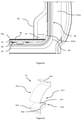
Figure 5 is an enlarged cross-sectional view of the lower portion of a conventional gangway bridge assembly between two rail vehicles, parallel to the vertical median plane, under normal conditions. -
Figure 6 is an enlarged fragmentary view of the lower left corner ofFigure 4 in a transverse vertical plan, seen from the usable space. -
Figure 7 is an enlarged fragmentary view of the lower left portion ofFigure 5 , upon collision of the rail vehicles. -
Figure 8 is a view of the enlarged fragmentary view ofFigure 6 , seen from the outside. -
Figure 9 depicts an example retainer according to the invention. - With reference to
Figure 1 and Figure 2 , a set ofrail vehicles 10, eachrail vehicle 10 comprises afirst end 100 and a second end 100'. At least oneend 100 has anend wall 101 to which agangway 20 is connected.Footplate catchers 40 are provided, and located within theend wall 101. The gangway 20 provides passengers with a safe and comfortable means to move from one rail vehicle to the adjacent rail vehicle. One side of the gangway 20 is connected to theend wall 101 and on the opposite side, to an adjacent rail vehicle. Aninner lining 22 defines an interior space of thegangway 20. The interior space dedicated to accommodating passengers extends along the full length of the gangway 20 and defines apassage 21. - The
end wall 101 further provides passengers with an access means towards the adjacent rail vehicle. In particular, the access means can be adoorway 103. Thedoorway 103 allows passengers to walk from theusable space 102 towards thepassage 21 and the adjacent rail vehicle. In other words, thepassage 21 prolongs thedoorway 103 in the longitudinal direction. The doorway compriseslateral walls 103a and athreshold 103b. Thethreshold 103b is substantially flush with afloor 106 of theusable space 102. - Further shown is a coordinate system comprising a vertical axis z, the longitudinal axis x and lateral/transverse axis y. These axes x, y, z provide a Cartesian coordinate system, wherein the vertical axis z extends vertically. The longitudinal axis x can be a roll axis of the rail vehicle, wherein the lateral axis y can be a pitch axis of the rail vehicle.
-
Figure 3 is an enlarged fragmentary perspective view of a bottom portion of the doorway. Arecess 101c is provided in the lower section of theend wall 101. In particular, therecess 101c is provided at the bottom of thedoorway 103. The lower part of therecess 101c is formed essentially by thethreshold 103b. In a transverse plane perpendicular to the longitudinal direction, therecess 101c, is defined by the upper parts and the side parts of twonotches 101b. Therecess 101c extends in the longitudinal direction, over the entire thickness of theend wall 101. Therecess 101c is adapted to receive at least oneloose footplate footplates 300, in that the width and height of therecess 101c are greater than the width and height of the footplates. -
Figure 4 is an enlarged fragmentary inner perspective view of arail vehicle end 100. Therail vehicle end 100 includes an end section of theusable space 102. Theusable space 102 ends with theend wall 101 comprising mainly hollow profile elements. Aconventional interconnection gangway 20 flexibly connects the rail vehicle end 100 an adjacent rail vehicle end (not shown) belonging to an adjacent rail vehicle. The gangway 20, here represented entirely, comprises anouter bellow 23, an inner bellow comprising aninner lining 22 and abridge assembly 30 providing access to the adjacent rail vehicle. Theinner lining 22 surrounds thepassage 21 section of thegangway 20. Thepassage 21 is defined by itscross-section 21a and the length of thegangway 20. -
Figure 5 is a cross-sectional view showing thebridge assembly 30. Thebridge assembly 30 defines a lower limit of thepassage 21, substantially aligned with thefloor level 106a. Thebridge assembly 30 allows passengers to walk through thegangway 20. Thebridge assembly 30 comprises a set of one ormore footplates 300 resting on a scissor-type frame 34 and connected to theend wall 101. The set of one ormore footplates 300 comprisesbridge plates 31 attached to the end faces 101a, and acentral treadplate 32 resting partly on thebridge plate 31 and on thescissor type frame 34. - The scissor-
type frame 34 is extensible and is flexibly connected to both end faces 101a, 101a' of the adjacent rail vehicles. The scissor-type frame 34 can accommodate relative movements between the rail vehicles, as occurs in normal operation of a set of rail vehicles. The scissor-type frame 34 is used to support the weight of passengers walking through thepassage 21, more specifically passengers walking on thebridge assembly 30. - The gangway 20 and the
bridge assembly 30 are substantially symmetrical in a plane perpendicular to the longitudinal direction, and which includes the center of thetreadplate 32, so that the following description will be limited to the left portion ofFigure 5 . A proximal end of thebridge plate 31 is located along theend face 101a and connected to theend face 101a via a pivot joint in form of ahorizontal hinge 33. The distal end of thebridge plate 31 is resting on a slidingelement 35, the slidingelement 35 being supported by the scissor-type frame 34. The thickness of the slidingelement 35 is such that thebridge plate 31 is maintained in a substantially horizontal position when the rail vehicle is travelling on a flat track, i.e. when there is no vertical offset, nor pitch, between the two adjacent rail vehicles. The free-end of thetreadplate 32 can slide on thebridge plates 31 while the central portion of thetreadplate 32 is connected via atreadplate bolt 36 to the scissor-type frame 34 supporting thetreadplate 32. In normal operation, the load of passengers resting or walking on thebridge assembly 30 is thus mainly supported by the scissor-type frame 34. - As can be seen in
Figure 6 , the width of the set of one or more footplates is represented by the distance (W). - In this embodiment a
notch 101 b is provided at the bottom corner of thedoorway 103. Asecond notch 101b (not shown) is provided and located at a symmetric location on the other side of the doorway. Bothnotches 101b are symmetrical with regards to a verticalmedian plane 10a of therail vehicle 10. Thenotches 101 b ends transversally at a distance (V/2) from the verticalmedian plane 10a, (V) being the width of therecess 101c. The distance V is greater than the width (W), so that therecess 101c can receive the set offootplates 300. More specifically, therecess 101c can receive either one, or both, of thetreadplate 32 and thebridge plate 31, should they become loose and move towards theusable space 102 - The distance (U) represents the width of the lower portion of the
passage 21, while the width of thethreshold 103b is represented by the distance (S), which can be greater than U or equal to U. - In a vertical direction, the lower part of the
notches 101b extend below thethreshold 103b, and below thefootplates footplates 300, represented by the vertical distance (T). - When the 2 adjacent rail vehicles are horizontally aligned, the
bridge plate 31 is substantially at the same level as thethreshold 103b and thefloor level 106a. Since thetreadplate 32 is sliding over thebridge plate 31, thetreadplate 32 is thus located in a horizontal plane slightly above thethreshold 103b. Thenotch 101b is located behind theinner lining 22, so that thefootplate catchers 40 are not visible to passengers. - The effect of a collision on the
bridge assembly 30 ofFigure 5 is represented inFigure 7 , although here limited to half of the length of thegangway 20. For clarity purpose, the outer below 23 and theinner lining 22 are not shown. The distance between theend face 101a and the middle section of the gangway 20, which is represented by the longitudinal location of the center of thetreadplate 32, decreased. Thebridge plate 31 slid essentially horizontally between the treadplate 32 and the slidingelement 35, towards the adjacent rail vehicle, thus reducing the gap between the distal end thebridge plate 31 and thetreadplate bolt 36. - It can easily be understood from
Figure 7 , especially considering the area highlighted by the dotted-line ellipse, that a further decrease of the distance between the adjacent rail vehicles will see the distal end of thebridge plate 31 collide with thetreadplate bolt 36. Thebridge plate 31 will severe the connection between the treadplate 32 and the scissor-type frame 34 thus releasing thetreadplate 32. In such occurrence, thetreadplate 32 becomes loose. As the distance continues to decrease and the impact energy dissipates, theloose treadplate 32 will thrust towards theusable space 102, more specifically through theend wall 101, more specifically through therecess 101c. When thrusting through therecess 101c, theloose treadplate 32 will subsequently meet with thefootplate catchers 40. More specifically, theloose treadplate 32 would be stopped by theretainers 41. - The shape of the
retainers 41 is operative to orientate at least oneloose footplate footplates 300 towards thethreshold 103b when the at least oneloose footplate usable space 102. Theretainers 41 are located preferably beyond theinner lining 22 of the gangway 20 in the transverse direction, at a distance D from each other. The distance D is greater than the distance U and greater than S (as is represented inFigure 6 ). It can be easily understood fromfigure 7 that if the connection between thebridge plate 31 and thehinge 33 is severed in a collision, or thehinge 33 connecting thebridge plate 31 to theend wall 101 teared off from theend face 101a, aloose bridge plate 31 may also thrust towards theusable space 102 and be stopped by theretainers 41. - The front view of
Figure 6 is shown onFigure 8 , seen from outside therail vehicle 10. The gangway 20 is at the foreground whereas theend wall 101 is in the background. Theend wall 101 receives theretainers 41, within thenotches 101b. The lower portion of theinner lining 22 ends slightly above thebridge assembly 30, so that it does not interfere with inherent movements of eitherfootplates - One
retainer 41 is shown onFigure 9 . The retainer comprises a sheet metal element. Theretainer 41 includes astop 411 for stopping aloose footplate stop 411 can be obtained by bending the metal sheet element. Theretainer 41 has afirst leg 412 extending upwards and asecond leg 413 extending downwards, first andsecond leg stop 411 and forming anindentation 417 for receiving at least oneloose footplate first leg 412 acts as a guide for a loose footplate, guiding the footplate towards thestop 411 and towards thethreshold 103b. In the embodiment depicted inFigure 7 , thestop 411 is adjacent to thefloor level 106a. - The
retainer 41 has a first mountinginterface 414 extending from thefirst leg 412 and/or asecond mounting interface 415 extending from thesecond leg 413. Thesecond leg 413 comprises afurther bend 416, saidfurther bend 416 arranged between thestop 411 and thesecond mounting interface 415. In the present embodiment, thestop 411 and thesecond mounting interface 415 are, at least essentially, arranged on a common plane. First and/or second mounting interfaces are adapted for mounting at a mounting surface of the carbody shell, in particular at theend wall 101. As can be seen fromFigure 7 , a first mounting surface of the end wall, consisting of an intermediate rib from the end wall, extends essentially perpendicular to an inner plate of the end wall which defines a second mounting surface of the end wall (to improve a form fit between theretainer 41 and the end wall 101). In this particular configuration, theretainer 41 is of a substantially S-shape. -
Retainers 41 are designed so that they can deform upon impact of aloose footplate retainers 41, and more specifically thebend 416, provides elasticity to thefootplate catchers 40 and help absorbing the energy from a thrustingfootplate retainers 41 can unfold and, while they unfold, dissipate the kinetic energy from theloose footplate usable space 102. -
- 10
- Rail vehicle
10a Vertical median plane
100 Rail vehicle end
101 End wall
101a End face
101b Notch
101c Recess
102 Usable space
103 Doorway
103a Doorway lateral wall
103b Doorway threshold
106 Floor
106a Floor level
20 Gangway
21 Passage
21a Passage cross-section
22 Inner lining
23 Outer bellow
30 Bridge assembly
31 Bridge plate
32 Treadplate
33 Hinge
34 Scissor-type frame
35 Sliding element
36 Treadplate bolt
40 Footplate catcher
41 Retainer
300 Set of footplates
411 Stop
412 First leg
413 Second leg
414 First mounting interface
415 Second mounting interface
416 Bend
Claims (13)
- A rail vehicle (10), said rail vehicle (10) comprising a carbody shell, the carbody shell having an end wall (101) and a usable space (102), said end wall (101) comprising a doorway (103) for providing access to said usable space (102), said doorway (103) comprising lateral walls (103a) and a threshold (103b), wherein said end wall (101) further comprises at least two footplate catchers (40) located laterally at a distance D of each other, each laterally outside said threshold (103b), for preventing a set of one or more footplates (300) having a footplate width W greater than a threshold width S of the threshold (103b) and greater than the distance D, from entering the usable space (102).
- A rail vehicle according to claim 1, wherein the end wall (101) further comprises a substantially horizontal recess (101c) provided at the bottom of the doorway (103), said recess (101c) having a recess width V greater than the footplate width W of the set of one or more footplates (300).
- A rail vehicle according to claim 2, wherein the recess (101c) comprises at least two notches (101b) located at least partially at two opposite bottom corners of the doorway (103).
- A rail vehicle according to claim 3, wherein the footplate catcher (40) comprises at least one retainer (41) for stopping and/or holding at least one loose footplate (31,32) from the set of one or more footplates (300), the retainer (40) being arranged at least partially within the recess (101c).
- A rail vehicle according to claim 4, wherein the footplate catcher (40) comprises two retainers (41), each retainer (41) being located on either side of the doorway (103), wherein the retainers (41) are located at least partially within a transverse span of the footplates (31,32).
- A rail vehicle according to claim 5, wherein the retainers (41) are located outside a passage (21) through the gangway (20).
- A rail vehicle according to claim 6, wherein the retainers (41) are located beyond an inner lining (22) of the gangway (20), in a transverse direction, rendering the footplate catcher (40) invisible to the passengers.
- A rail vehicle according to claim 7, wherein the retainers (41) comprise a curved plate connected to the carbody shell, in particular to the end wall (101).
- A rail vehicle according to claim 8, wherein the retainers (41) are provided with a stop (411), a first leg (412) and a second leg (413), the first leg (412) extending from the stop (411) in a direction upwards, the second leg extending from the stop (411) in a direction downwards, at least one leg (412, 413) having its extremity connected to the carbody shell.
- A rail vehicle according to claim 7, wherein the retainer (41) provides an indentation (417) for receiving the at least one loose footplate (31, 32).
- A rail vehicle according to claim 9, wherein the retainer (40) is substantially S-shaped.
- Set of rail vehicles comprising at least two rail vehicles and a gangway (20) arranged between said two rail vehicles, at least one rail vehicle being designed according to one of the preceding claims, wherein the gangway (20) comprises at least one footplate (31, 32), and the footplate catcher (40) is located on the path of a loose footplate (31, 32) and is operative to prevent said loose footplate (31, 32) from entering said usable space (102), in the event of a collision.
- Set of rail vehicles according to claim 12, wherein the set of rail vehicles is provided with pairs of footplate catchers (40) opposing each other in the longitudinal direction.
Applications Claiming Priority (1)
| Application Number | Priority Date | Filing Date | Title |
|---|---|---|---|
| GB2010996.3A GB2598541B (en) | 2020-07-16 | 2020-07-16 | Rail vehicle provided with an end wall, a doorway and footplate catchers |
Publications (2)
| Publication Number | Publication Date |
|---|---|
| EP3939851A1 true EP3939851A1 (en) | 2022-01-19 |
| EP3939851B1 EP3939851B1 (en) | 2022-07-27 |
Family
ID=72338879
Family Applications (1)
| Application Number | Title | Priority Date | Filing Date |
|---|---|---|---|
| EP21180469.5A Active EP3939851B1 (en) | 2020-07-16 | 2021-06-18 | Rail vehicle provided with an end wall, a doorway and footplace catchers |
Country Status (5)
| Country | Link |
|---|---|
| US (1) | US12179810B2 (en) |
| EP (1) | EP3939851B1 (en) |
| CN (1) | CN113942530B (en) |
| ES (1) | ES2929428T3 (en) |
| GB (1) | GB2598541B (en) |
Cited By (1)
| Publication number | Priority date | Publication date | Assignee | Title |
|---|---|---|---|---|
| EP4215427A1 (en) * | 2022-01-20 | 2023-07-26 | ALSTOM Holdings | Method of assembling an interior module in a car body of a rail vehicle and associated car body |
Citations (4)
| Publication number | Priority date | Publication date | Assignee | Title |
|---|---|---|---|---|
| EP0683080A1 (en) * | 1994-05-20 | 1995-11-22 | NARITA MFG., Ltd. | Footplate apparatus for connecting pathway between vehicles |
| EP0685375A1 (en) | 1994-06-02 | 1995-12-06 | NARITA MFG., Ltd. | Footplate apparatus for connecting pathway between vehicles |
| EP1564101A1 (en) * | 2004-02-10 | 2005-08-17 | HÜBNER GmbH | Footplate for an interconnecting gangway with a bellow, for the communication passage between articulated railway vehicles. |
| EP2700553A1 (en) | 2012-08-22 | 2014-02-26 | Hübner GmbH | Bridge with a tunnel-shaped enveloping bellows between two vehicles joined through an articulated connection |
Family Cites Families (5)
| Publication number | Priority date | Publication date | Assignee | Title |
|---|---|---|---|---|
| US4677918A (en) * | 1985-08-23 | 1987-07-07 | Thrall Car Manufacturing Company | Railroad car with retractable closure track held down by bridge plate |
| EP0854813B1 (en) * | 1996-07-01 | 1999-08-11 | HÜBNER Gummi- und Kunststoff GmbH | Communication point between two vehicles flexibly connected to each other, e.g. railway coaches or underground coaches |
| JP4417821B2 (en) * | 2004-11-22 | 2010-02-17 | 株式会社日立製作所 | Railway vehicle with a through-passage |
| KR101856590B1 (en) * | 2016-10-24 | 2018-05-14 | 한국철도기술연구원 | Footplate structure for gangway of a mountain railway |
| CN107571880B (en) * | 2017-09-08 | 2019-06-14 | 株洲九方制动设备有限公司 | Cab apron assembly and low-floor tramcar |
-
2020
- 2020-07-16 GB GB2010996.3A patent/GB2598541B/en active Active
-
2021
- 2021-06-18 EP EP21180469.5A patent/EP3939851B1/en active Active
- 2021-06-18 ES ES21180469T patent/ES2929428T3/en active Active
- 2021-07-14 US US17/375,074 patent/US12179810B2/en active Active
- 2021-07-14 CN CN202110793119.9A patent/CN113942530B/en active Active
Patent Citations (4)
| Publication number | Priority date | Publication date | Assignee | Title |
|---|---|---|---|---|
| EP0683080A1 (en) * | 1994-05-20 | 1995-11-22 | NARITA MFG., Ltd. | Footplate apparatus for connecting pathway between vehicles |
| EP0685375A1 (en) | 1994-06-02 | 1995-12-06 | NARITA MFG., Ltd. | Footplate apparatus for connecting pathway between vehicles |
| EP1564101A1 (en) * | 2004-02-10 | 2005-08-17 | HÜBNER GmbH | Footplate for an interconnecting gangway with a bellow, for the communication passage between articulated railway vehicles. |
| EP2700553A1 (en) | 2012-08-22 | 2014-02-26 | Hübner GmbH | Bridge with a tunnel-shaped enveloping bellows between two vehicles joined through an articulated connection |
Cited By (1)
| Publication number | Priority date | Publication date | Assignee | Title |
|---|---|---|---|---|
| EP4215427A1 (en) * | 2022-01-20 | 2023-07-26 | ALSTOM Holdings | Method of assembling an interior module in a car body of a rail vehicle and associated car body |
Also Published As
| Publication number | Publication date |
|---|---|
| GB2598541B (en) | 2022-12-07 |
| CN113942530B (en) | 2025-09-09 |
| US20220017123A1 (en) | 2022-01-20 |
| GB2598541A (en) | 2022-03-09 |
| ES2929428T3 (en) | 2022-11-29 |
| EP3939851B1 (en) | 2022-07-27 |
| GB202010996D0 (en) | 2020-09-02 |
| CN113942530A (en) | 2022-01-18 |
| US12179810B2 (en) | 2024-12-31 |
Similar Documents
| Publication | Publication Date | Title |
|---|---|---|
| US7543537B2 (en) | Crumple element comprising a guiding mechanism | |
| US7536958B2 (en) | Passenger rail car | |
| US8596903B2 (en) | Method for absorbing a vehicle impact using kinetic friction force and rolling force produced by the dragging of a surface of rolled tube, and vehicle impact absorbing apparatus using same | |
| EP2412599B1 (en) | Railcar | |
| JP5161251B2 (en) | Railway vehicle with shock absorbing structure | |
| EP3939851B1 (en) | Rail vehicle provided with an end wall, a doorway and footplace catchers | |
| CN112373576A (en) | Front floor assembly structure | |
| AU2005200402B2 (en) | Door threshold for access to the interior of a railway vehicle | |
| CA2529234C (en) | Anti-climbing device for railway carriages | |
| CA2574019C (en) | Climbing guard for railway vehicles | |
| CN115817553B (en) | End chassis structure and rail vehicle | |
| US7506590B2 (en) | Junction between railway vehicles with anti-climbing protective devices | |
| CA2967235A1 (en) | Railcar | |
| TW200305535A (en) | Elevator device | |
| CN115230749A (en) | Cab structure and rail vehicle | |
| EP3357785B1 (en) | Energy absorption device and rail vehicle having same | |
| JP7531536B2 (en) | Railway vehicle sidewall structure | |
| EP0685375B1 (en) | A connecting pathway between vehicles with a footplate apparatus | |
| CN121591081A (en) | Dual guide rails and elevator components | |
| JP2024066680A (en) | Rail vehicles | |
| JP2025147881A (en) | Railway vehicle |
Legal Events
| Date | Code | Title | Description |
|---|---|---|---|
| PUAI | Public reference made under article 153(3) epc to a published international application that has entered the european phase |
Free format text: ORIGINAL CODE: 0009012 |
|
| STAA | Information on the status of an ep patent application or granted ep patent |
Free format text: STATUS: THE APPLICATION HAS BEEN PUBLISHED |
|
| STAA | Information on the status of an ep patent application or granted ep patent |
Free format text: STATUS: REQUEST FOR EXAMINATION WAS MADE |
|
| AK | Designated contracting states |
Kind code of ref document: A1 Designated state(s): AL AT BE BG CH CY CZ DE DK EE ES FI FR GB GR HR HU IE IS IT LI LT LU LV MC MK MT NL NO PL PT RO RS SE SI SK SM TR |
|
| 17P | Request for examination filed |
Effective date: 20211223 |
|
| RBV | Designated contracting states (corrected) |
Designated state(s): AL AT BE BG CH CY CZ DE DK EE ES FI FR GB GR HR HU IE IS IT LI LT LU LV MC MK MT NL NO PL PT RO RS SE SI SK SM TR |
|
| GRAP | Despatch of communication of intention to grant a patent |
Free format text: ORIGINAL CODE: EPIDOSNIGR1 |
|
| STAA | Information on the status of an ep patent application or granted ep patent |
Free format text: STATUS: GRANT OF PATENT IS INTENDED |
|
| INTG | Intention to grant announced |
Effective date: 20220217 |
|
| GRAS | Grant fee paid |
Free format text: ORIGINAL CODE: EPIDOSNIGR3 |
|
| GRAA | (expected) grant |
Free format text: ORIGINAL CODE: 0009210 |
|
| STAA | Information on the status of an ep patent application or granted ep patent |
Free format text: STATUS: THE PATENT HAS BEEN GRANTED |
|
| AK | Designated contracting states |
Kind code of ref document: B1 Designated state(s): AL AT BE BG CH CY CZ DE DK EE ES FI FR GB GR HR HU IE IS IT LI LT LU LV MC MK MT NL NO PL PT RO RS SE SI SK SM TR |
|
| REG | Reference to a national code |
Ref country code: CH Ref legal event code: EP |
|
| REG | Reference to a national code |
Ref country code: DE Ref legal event code: R096 Ref document number: 602021000245 Country of ref document: DE |
|
| REG | Reference to a national code |
Ref country code: AT Ref legal event code: REF Ref document number: 1506880 Country of ref document: AT Kind code of ref document: T Effective date: 20220815 |
|
| REG | Reference to a national code |
Ref country code: IE Ref legal event code: FG4D |
|
| REG | Reference to a national code |
Ref country code: CH Ref legal event code: PK Free format text: BERICHTIGUNGEN |
|
| REG | Reference to a national code |
Ref country code: SE Ref legal event code: TRGR |
|
| REG | Reference to a national code |
Ref country code: LT Ref legal event code: MG9D |
|
| RIN2 | Information on inventor provided after grant (corrected) |
Inventor name: EDWARDS, JONATHAN |
|
| REG | Reference to a national code |
Ref country code: ES Ref legal event code: FG2A Ref document number: 2929428 Country of ref document: ES Kind code of ref document: T3 Effective date: 20221129 |
|
| REG | Reference to a national code |
Ref country code: NL Ref legal event code: MP Effective date: 20220727 |
|
| REG | Reference to a national code |
Ref country code: NO Ref legal event code: T2 Effective date: 20220727 |
|
| PG25 | Lapsed in a contracting state [announced via postgrant information from national office to epo] |
Ref country code: RS Free format text: LAPSE BECAUSE OF FAILURE TO SUBMIT A TRANSLATION OF THE DESCRIPTION OR TO PAY THE FEE WITHIN THE PRESCRIBED TIME-LIMIT Effective date: 20220727 Ref country code: PT Free format text: LAPSE BECAUSE OF FAILURE TO SUBMIT A TRANSLATION OF THE DESCRIPTION OR TO PAY THE FEE WITHIN THE PRESCRIBED TIME-LIMIT Effective date: 20221128 Ref country code: NL Free format text: LAPSE BECAUSE OF FAILURE TO SUBMIT A TRANSLATION OF THE DESCRIPTION OR TO PAY THE FEE WITHIN THE PRESCRIBED TIME-LIMIT Effective date: 20220727 Ref country code: LV Free format text: LAPSE BECAUSE OF FAILURE TO SUBMIT A TRANSLATION OF THE DESCRIPTION OR TO PAY THE FEE WITHIN THE PRESCRIBED TIME-LIMIT Effective date: 20220727 Ref country code: LT Free format text: LAPSE BECAUSE OF FAILURE TO SUBMIT A TRANSLATION OF THE DESCRIPTION OR TO PAY THE FEE WITHIN THE PRESCRIBED TIME-LIMIT Effective date: 20220727 Ref country code: FI Free format text: LAPSE BECAUSE OF FAILURE TO SUBMIT A TRANSLATION OF THE DESCRIPTION OR TO PAY THE FEE WITHIN THE PRESCRIBED TIME-LIMIT Effective date: 20220727 |
|
| REG | Reference to a national code |
Ref country code: AT Ref legal event code: MK05 Ref document number: 1506880 Country of ref document: AT Kind code of ref document: T Effective date: 20220727 |
|
| PG25 | Lapsed in a contracting state [announced via postgrant information from national office to epo] |
Ref country code: PL Free format text: LAPSE BECAUSE OF FAILURE TO SUBMIT A TRANSLATION OF THE DESCRIPTION OR TO PAY THE FEE WITHIN THE PRESCRIBED TIME-LIMIT Effective date: 20220727 Ref country code: IS Free format text: LAPSE BECAUSE OF FAILURE TO SUBMIT A TRANSLATION OF THE DESCRIPTION OR TO PAY THE FEE WITHIN THE PRESCRIBED TIME-LIMIT Effective date: 20221127 Ref country code: HR Free format text: LAPSE BECAUSE OF FAILURE TO SUBMIT A TRANSLATION OF THE DESCRIPTION OR TO PAY THE FEE WITHIN THE PRESCRIBED TIME-LIMIT Effective date: 20220727 Ref country code: GR Free format text: LAPSE BECAUSE OF FAILURE TO SUBMIT A TRANSLATION OF THE DESCRIPTION OR TO PAY THE FEE WITHIN THE PRESCRIBED TIME-LIMIT Effective date: 20221028 |
|
| PG25 | Lapsed in a contracting state [announced via postgrant information from national office to epo] |
Ref country code: SM Free format text: LAPSE BECAUSE OF FAILURE TO SUBMIT A TRANSLATION OF THE DESCRIPTION OR TO PAY THE FEE WITHIN THE PRESCRIBED TIME-LIMIT Effective date: 20220727 Ref country code: RO Free format text: LAPSE BECAUSE OF FAILURE TO SUBMIT A TRANSLATION OF THE DESCRIPTION OR TO PAY THE FEE WITHIN THE PRESCRIBED TIME-LIMIT Effective date: 20220727 Ref country code: DK Free format text: LAPSE BECAUSE OF FAILURE TO SUBMIT A TRANSLATION OF THE DESCRIPTION OR TO PAY THE FEE WITHIN THE PRESCRIBED TIME-LIMIT Effective date: 20220727 Ref country code: CZ Free format text: LAPSE BECAUSE OF FAILURE TO SUBMIT A TRANSLATION OF THE DESCRIPTION OR TO PAY THE FEE WITHIN THE PRESCRIBED TIME-LIMIT Effective date: 20220727 Ref country code: AT Free format text: LAPSE BECAUSE OF FAILURE TO SUBMIT A TRANSLATION OF THE DESCRIPTION OR TO PAY THE FEE WITHIN THE PRESCRIBED TIME-LIMIT Effective date: 20220727 |
|
| REG | Reference to a national code |
Ref country code: DE Ref legal event code: R097 Ref document number: 602021000245 Country of ref document: DE |
|
| PG25 | Lapsed in a contracting state [announced via postgrant information from national office to epo] |
Ref country code: SK Free format text: LAPSE BECAUSE OF FAILURE TO SUBMIT A TRANSLATION OF THE DESCRIPTION OR TO PAY THE FEE WITHIN THE PRESCRIBED TIME-LIMIT Effective date: 20220727 Ref country code: EE Free format text: LAPSE BECAUSE OF FAILURE TO SUBMIT A TRANSLATION OF THE DESCRIPTION OR TO PAY THE FEE WITHIN THE PRESCRIBED TIME-LIMIT Effective date: 20220727 |
|
| PLBE | No opposition filed within time limit |
Free format text: ORIGINAL CODE: 0009261 |
|
| STAA | Information on the status of an ep patent application or granted ep patent |
Free format text: STATUS: NO OPPOSITION FILED WITHIN TIME LIMIT |
|
| PG25 | Lapsed in a contracting state [announced via postgrant information from national office to epo] |
Ref country code: AL Free format text: LAPSE BECAUSE OF FAILURE TO SUBMIT A TRANSLATION OF THE DESCRIPTION OR TO PAY THE FEE WITHIN THE PRESCRIBED TIME-LIMIT Effective date: 20220727 |
|
| 26N | No opposition filed |
Effective date: 20230502 |
|
| P01 | Opt-out of the competence of the unified patent court (upc) registered |
Effective date: 20231025 |
|
| PG25 | Lapsed in a contracting state [announced via postgrant information from national office to epo] |
Ref country code: MC Free format text: LAPSE BECAUSE OF FAILURE TO SUBMIT A TRANSLATION OF THE DESCRIPTION OR TO PAY THE FEE WITHIN THE PRESCRIBED TIME-LIMIT Effective date: 20220727 |
|
| PG25 | Lapsed in a contracting state [announced via postgrant information from national office to epo] |
Ref country code: MC Free format text: LAPSE BECAUSE OF FAILURE TO SUBMIT A TRANSLATION OF THE DESCRIPTION OR TO PAY THE FEE WITHIN THE PRESCRIBED TIME-LIMIT Effective date: 20220727 |
|
| REG | Reference to a national code |
Ref country code: BE Ref legal event code: MM Effective date: 20230630 |
|
| PG25 | Lapsed in a contracting state [announced via postgrant information from national office to epo] |
Ref country code: LU Free format text: LAPSE BECAUSE OF NON-PAYMENT OF DUE FEES Effective date: 20230618 |
|
| REG | Reference to a national code |
Ref country code: IE Ref legal event code: MM4A |
|
| PG25 | Lapsed in a contracting state [announced via postgrant information from national office to epo] |
Ref country code: LU Free format text: LAPSE BECAUSE OF NON-PAYMENT OF DUE FEES Effective date: 20230618 |
|
| PG25 | Lapsed in a contracting state [announced via postgrant information from national office to epo] |
Ref country code: IE Free format text: LAPSE BECAUSE OF NON-PAYMENT OF DUE FEES Effective date: 20230618 |
|
| PG25 | Lapsed in a contracting state [announced via postgrant information from national office to epo] |
Ref country code: IE Free format text: LAPSE BECAUSE OF NON-PAYMENT OF DUE FEES Effective date: 20230618 |
|
| PG25 | Lapsed in a contracting state [announced via postgrant information from national office to epo] |
Ref country code: BE Free format text: LAPSE BECAUSE OF NON-PAYMENT OF DUE FEES Effective date: 20230630 |
|
| PG25 | Lapsed in a contracting state [announced via postgrant information from national office to epo] |
Ref country code: BG Free format text: LAPSE BECAUSE OF FAILURE TO SUBMIT A TRANSLATION OF THE DESCRIPTION OR TO PAY THE FEE WITHIN THE PRESCRIBED TIME-LIMIT Effective date: 20220727 |
|
| PG25 | Lapsed in a contracting state [announced via postgrant information from national office to epo] |
Ref country code: BG Free format text: LAPSE BECAUSE OF FAILURE TO SUBMIT A TRANSLATION OF THE DESCRIPTION OR TO PAY THE FEE WITHIN THE PRESCRIBED TIME-LIMIT Effective date: 20220727 |
|
| PG25 | Lapsed in a contracting state [announced via postgrant information from national office to epo] |
Ref country code: CY Free format text: LAPSE BECAUSE OF FAILURE TO SUBMIT A TRANSLATION OF THE DESCRIPTION OR TO PAY THE FEE WITHIN THE PRESCRIBED TIME-LIMIT; INVALID AB INITIO Effective date: 20210618 |
|
| PGFP | Annual fee paid to national office [announced via postgrant information from national office to epo] |
Ref country code: SE Payment date: 20250618 Year of fee payment: 5 |
|
| PG25 | Lapsed in a contracting state [announced via postgrant information from national office to epo] |
Ref country code: HU Free format text: LAPSE BECAUSE OF FAILURE TO SUBMIT A TRANSLATION OF THE DESCRIPTION OR TO PAY THE FEE WITHIN THE PRESCRIBED TIME-LIMIT; INVALID AB INITIO Effective date: 20210618 |
|
| PGFP | Annual fee paid to national office [announced via postgrant information from national office to epo] |
Ref country code: ES Payment date: 20250731 Year of fee payment: 5 |
|
| PGFP | Annual fee paid to national office [announced via postgrant information from national office to epo] |
Ref country code: CH Payment date: 20250701 Year of fee payment: 5 |
|
| PG25 | Lapsed in a contracting state [announced via postgrant information from national office to epo] |
Ref country code: TR Free format text: LAPSE BECAUSE OF FAILURE TO SUBMIT A TRANSLATION OF THE DESCRIPTION OR TO PAY THE FEE WITHIN THE PRESCRIBED TIME-LIMIT Effective date: 20220727 |
|
| PG25 | Lapsed in a contracting state [announced via postgrant information from national office to epo] |
Ref country code: SI Free format text: LAPSE BECAUSE OF FAILURE TO SUBMIT A TRANSLATION OF THE DESCRIPTION OR TO PAY THE FEE WITHIN THE PRESCRIBED TIME-LIMIT Effective date: 20220727 |
|
| REG | Reference to a national code |
Ref country code: CH Ref legal event code: U11 Free format text: ST27 STATUS EVENT CODE: U-0-0-U10-U11 (AS PROVIDED BY THE NATIONAL OFFICE) Effective date: 20260701 |
|
| PGFP | Annual fee paid to national office [announced via postgrant information from national office to epo] |
Ref country code: GB Payment date: 20260626 Year of fee payment: 6 |
|
| PGFP | Annual fee paid to national office [announced via postgrant information from national office to epo] |
Ref country code: IT Payment date: 20260623 Year of fee payment: 6 |
|
| PGFP | Annual fee paid to national office [announced via postgrant information from national office to epo] |
Ref country code: DE Payment date: 20260622 Year of fee payment: 6 |
|
| PGFP | Annual fee paid to national office [announced via postgrant information from national office to epo] |
Ref country code: NO Payment date: 20260622 Year of fee payment: 6 |
|
| PG25 | Lapsed in a contracting state [announced via postgrant information from national office to epo] |
Ref country code: MT Free format text: LAPSE BECAUSE OF NON-PAYMENT OF DUE FEES Effective date: 20230618 |
|
| PGFP | Annual fee paid to national office [announced via postgrant information from national office to epo] |
Ref country code: FR Payment date: 20260626 Year of fee payment: 6 |