EP3939773B1 - Verfahren und vorrichtung zur herstellung von artikeln durch additive fertigung - Google Patents
Verfahren und vorrichtung zur herstellung von artikeln durch additive fertigung Download PDFInfo
- Publication number
- EP3939773B1 EP3939773B1 EP20768937.3A EP20768937A EP3939773B1 EP 3939773 B1 EP3939773 B1 EP 3939773B1 EP 20768937 A EP20768937 A EP 20768937A EP 3939773 B1 EP3939773 B1 EP 3939773B1
- Authority
- EP
- European Patent Office
- Prior art keywords
- axis
- receiving surface
- structural element
- print head
- cylindrically shaped
- Prior art date
- Legal status (The legal status is an assumption and is not a legal conclusion. Google has not performed a legal analysis and makes no representation as to the accuracy of the status listed.)
- Active
Links
Images


Classifications
-
- B—PERFORMING OPERATIONS; TRANSPORTING
- B29—WORKING OF PLASTICS; WORKING OF SUBSTANCES IN A PLASTIC STATE IN GENERAL
- B29C—SHAPING OR JOINING OF PLASTICS; SHAPING OF MATERIAL IN A PLASTIC STATE, NOT OTHERWISE PROVIDED FOR; AFTER-TREATMENT OF THE SHAPED PRODUCTS, e.g. REPAIRING
- B29C64/00—Additive manufacturing, i.e. manufacturing of three-dimensional [3D] objects by additive deposition, additive agglomeration or additive layering, e.g. by 3D printing, stereolithography or selective laser sintering
- B29C64/10—Processes of additive manufacturing
- B29C64/106—Processes of additive manufacturing using only liquids or viscous materials, e.g. depositing a continuous bead of viscous material
- B29C64/118—Processes of additive manufacturing using only liquids or viscous materials, e.g. depositing a continuous bead of viscous material using filamentary material being melted, e.g. fused deposition modelling [FDM]
-
- B—PERFORMING OPERATIONS; TRANSPORTING
- B29—WORKING OF PLASTICS; WORKING OF SUBSTANCES IN A PLASTIC STATE IN GENERAL
- B29C—SHAPING OR JOINING OF PLASTICS; SHAPING OF MATERIAL IN A PLASTIC STATE, NOT OTHERWISE PROVIDED FOR; AFTER-TREATMENT OF THE SHAPED PRODUCTS, e.g. REPAIRING
- B29C64/00—Additive manufacturing, i.e. manufacturing of three-dimensional [3D] objects by additive deposition, additive agglomeration or additive layering, e.g. by 3D printing, stereolithography or selective laser sintering
- B29C64/20—Apparatus for additive manufacturing; Details thereof or accessories therefor
- B29C64/205—Means for applying layers
- B29C64/209—Heads; Nozzles
-
- B—PERFORMING OPERATIONS; TRANSPORTING
- B29—WORKING OF PLASTICS; WORKING OF SUBSTANCES IN A PLASTIC STATE IN GENERAL
- B29C—SHAPING OR JOINING OF PLASTICS; SHAPING OF MATERIAL IN A PLASTIC STATE, NOT OTHERWISE PROVIDED FOR; AFTER-TREATMENT OF THE SHAPED PRODUCTS, e.g. REPAIRING
- B29C64/00—Additive manufacturing, i.e. manufacturing of three-dimensional [3D] objects by additive deposition, additive agglomeration or additive layering, e.g. by 3D printing, stereolithography or selective laser sintering
- B29C64/20—Apparatus for additive manufacturing; Details thereof or accessories therefor
- B29C64/227—Driving means
- B29C64/236—Driving means for motion in a direction within the plane of a layer
-
- B—PERFORMING OPERATIONS; TRANSPORTING
- B29—WORKING OF PLASTICS; WORKING OF SUBSTANCES IN A PLASTIC STATE IN GENERAL
- B29C—SHAPING OR JOINING OF PLASTICS; SHAPING OF MATERIAL IN A PLASTIC STATE, NOT OTHERWISE PROVIDED FOR; AFTER-TREATMENT OF THE SHAPED PRODUCTS, e.g. REPAIRING
- B29C64/00—Additive manufacturing, i.e. manufacturing of three-dimensional [3D] objects by additive deposition, additive agglomeration or additive layering, e.g. by 3D printing, stereolithography or selective laser sintering
- B29C64/20—Apparatus for additive manufacturing; Details thereof or accessories therefor
- B29C64/227—Driving means
- B29C64/241—Driving means for rotary motion
-
- B—PERFORMING OPERATIONS; TRANSPORTING
- B29—WORKING OF PLASTICS; WORKING OF SUBSTANCES IN A PLASTIC STATE IN GENERAL
- B29C—SHAPING OR JOINING OF PLASTICS; SHAPING OF MATERIAL IN A PLASTIC STATE, NOT OTHERWISE PROVIDED FOR; AFTER-TREATMENT OF THE SHAPED PRODUCTS, e.g. REPAIRING
- B29C64/00—Additive manufacturing, i.e. manufacturing of three-dimensional [3D] objects by additive deposition, additive agglomeration or additive layering, e.g. by 3D printing, stereolithography or selective laser sintering
- B29C64/20—Apparatus for additive manufacturing; Details thereof or accessories therefor
- B29C64/245—Platforms or substrates
-
- B—PERFORMING OPERATIONS; TRANSPORTING
- B29—WORKING OF PLASTICS; WORKING OF SUBSTANCES IN A PLASTIC STATE IN GENERAL
- B29C—SHAPING OR JOINING OF PLASTICS; SHAPING OF MATERIAL IN A PLASTIC STATE, NOT OTHERWISE PROVIDED FOR; AFTER-TREATMENT OF THE SHAPED PRODUCTS, e.g. REPAIRING
- B29C64/00—Additive manufacturing, i.e. manufacturing of three-dimensional [3D] objects by additive deposition, additive agglomeration or additive layering, e.g. by 3D printing, stereolithography or selective laser sintering
- B29C64/30—Auxiliary operations or equipment
- B29C64/386—Data acquisition or data processing for additive manufacturing
- B29C64/393—Data acquisition or data processing for additive manufacturing for controlling or regulating additive manufacturing processes
-
- B—PERFORMING OPERATIONS; TRANSPORTING
- B33—ADDITIVE MANUFACTURING TECHNOLOGY
- B33Y—ADDITIVE MANUFACTURING, i.e. MANUFACTURING OF THREE-DIMENSIONAL [3D] OBJECTS BY ADDITIVE DEPOSITION, ADDITIVE AGGLOMERATION OR ADDITIVE LAYERING, e.g. BY 3D PRINTING, STEREOLITHOGRAPHY OR SELECTIVE LASER SINTERING
- B33Y50/00—Data acquisition or data processing for additive manufacturing
-
- B—PERFORMING OPERATIONS; TRANSPORTING
- B29—WORKING OF PLASTICS; WORKING OF SUBSTANCES IN A PLASTIC STATE IN GENERAL
- B29C—SHAPING OR JOINING OF PLASTICS; SHAPING OF MATERIAL IN A PLASTIC STATE, NOT OTHERWISE PROVIDED FOR; AFTER-TREATMENT OF THE SHAPED PRODUCTS, e.g. REPAIRING
- B29C64/00—Additive manufacturing, i.e. manufacturing of three-dimensional [3D] objects by additive deposition, additive agglomeration or additive layering, e.g. by 3D printing, stereolithography or selective laser sintering
- B29C64/30—Auxiliary operations or equipment
- B29C64/379—Handling of additively manufactured objects, e.g. using robots
-
- B—PERFORMING OPERATIONS; TRANSPORTING
- B33—ADDITIVE MANUFACTURING TECHNOLOGY
- B33Y—ADDITIVE MANUFACTURING, i.e. MANUFACTURING OF THREE-DIMENSIONAL [3D] OBJECTS BY ADDITIVE DEPOSITION, ADDITIVE AGGLOMERATION OR ADDITIVE LAYERING, e.g. BY 3D PRINTING, STEREOLITHOGRAPHY OR SELECTIVE LASER SINTERING
- B33Y10/00—Processes of additive manufacturing
-
- B—PERFORMING OPERATIONS; TRANSPORTING
- B33—ADDITIVE MANUFACTURING TECHNOLOGY
- B33Y—ADDITIVE MANUFACTURING, i.e. MANUFACTURING OF THREE-DIMENSIONAL [3D] OBJECTS BY ADDITIVE DEPOSITION, ADDITIVE AGGLOMERATION OR ADDITIVE LAYERING, e.g. BY 3D PRINTING, STEREOLITHOGRAPHY OR SELECTIVE LASER SINTERING
- B33Y30/00—Apparatus for additive manufacturing; Details thereof or accessories therefor
-
- B—PERFORMING OPERATIONS; TRANSPORTING
- B33—ADDITIVE MANUFACTURING TECHNOLOGY
- B33Y—ADDITIVE MANUFACTURING, i.e. MANUFACTURING OF THREE-DIMENSIONAL [3D] OBJECTS BY ADDITIVE DEPOSITION, ADDITIVE AGGLOMERATION OR ADDITIVE LAYERING, e.g. BY 3D PRINTING, STEREOLITHOGRAPHY OR SELECTIVE LASER SINTERING
- B33Y50/00—Data acquisition or data processing for additive manufacturing
- B33Y50/02—Data acquisition or data processing for additive manufacturing for controlling or regulating additive manufacturing processes
Definitions
- the invention relates to the technology of layerwise objects production based on a digital model by the way of layerwise application of material, when producing 3D objects using an additive process.
- FFF/FDM Fuse Deposition Modeling
- the FDM process includes the following stages: dividing of a 3D digital model into the plurality of thin flat layers and compiling a program for each of such layers' production, the said program including a plurality of the printing head linear movements accompanied by the feeding of the material.
- the totality of each of the layers' production programs is combined into the object production program as a whole and is sent to the additive production system that creates the object in a layerwise manner based on this program.
- Each layer is applied over the previous layer until the object is completely built.
- the accessory material can be used for supporting the overhanging elements of the object.
- the position of the extrusion head relative the substrate is then augmented along the Z-axis (perpendicularly to the X-Y piane), after which the process is repeated to form a 3D model resembling the digital representation (e.g., application U S2013224423, publication date 29.08.2013 , STRATASYS INC.)
- a 3D printer comprising a receiving cylindrical surface rotating about its own axis and an applicator configured to apply the material onto the said surface, wherein the applicator and the receiving cylindrical surface travel relative one another in the direction that is transverse to the rotation axis.
- a controller that is part of a 3D printer accepts the object production program, the instruction being represented in the form of a plurality of linear (or angular) movements along each of the 3D printer axes.
- the controller coordinates the rotation of the receiving cylindrical surface, the applicator offset relative thereof and the process of the material application by the applicator; the simultaneous movement of the print head and of the produced object along the said elements causing the formation of the three dimensional (curved) layers of material.
- WO 2011/011818 A1 also discloses additive manufacturing devices and methods with cylindrically shaped receiving surfaces.
- the method of production consists in the determination of the object production program for a device, based on the 3D model of the object; the said program comprising a plurality of the curved layers of the material that have to be sequentially applied by the device.
- This program is sent to the printing device that applies the material onto the receiving cylindrical surface by flat layers.
- An object production device comprising a receiving cylindrical surface for receiving the layers of the material, a drive for rotating a rod and a print head for applying the material onto the receiving cylindrical surface for the formation of an object, wherein the receiving cylindrical surface is fixed in a rotor collet closing mechanism.
- the object production method includes the application of the material onto the rod by a print head, the rod rotation, the moving of the print head in the direction parallel to the longitudinal axis of the rod and the subsequent removal of the cylindrical working surface after the object is produced (application US2016096323 A1, date of publication 07.04.2016 , Tyco Electronics Corp.)
- a method of the objects production includes controlling the receiving cylindrical surface rotation mechanism controller (the same cylindrical surface being fixed within the bounds of at least two supports), the formation of layers by a plurality of ejectors arranged in any of at least two print heads provided with various materials on a rotating receiving cylindrical surface, the operation of a controller with at least one actuating mechanism operably linked to at least two print heads and a hardening device providing each of the print heads' and the hardening device' movement independent of one another in the direction that is parallel to the cylindrical working surface rotation axis, to ensure the forming and hardening of layers on the rotating cylindrical working surface (application CIIIA US2018244033 A1, date of publication 30.08.2018 , Xerox Corp.)
- the disadvantage of the described 3D objects production method of Xerox Corp. consists in the high object production labor content and the limited variety of the produced objects shapes due to the necessity of conducting the printing process on a prefabricated receiving cylindrical surface that becomes part of the object and requires further mechanical processing or the removal by certain means. That said, the produced object should necessarily be bigger in thickness and smaller in length than the cylindrical working surface.
- this method provides only for the production of cylindrical products (rotation bodies), which limits the variety of produced objects.
- a 3D printer which comprises a printing surface configured to rotate around its axis, a print head arranged in close proximity of the working surface and directed perpendicularly to it (wherein the print head is configured to apply the material used in the production of the object at least onto a portion of the working surface or heated element arranged at least on a portion of the working surface), and a base located in close proximity of the print head and contacting the print surface, wherein the base is configured to move in the forward, backward and lateral directions relative to the print head (application US20160318247 A1, date of publication 03.11.2016 , Warsaw Orthopedic Inc.)
- Warsaw Orthopedic Inc. The disadvantage of the described 3D printer of Warsaw Orthopedic Inc. consists in the limited variety of the produced objects shapes due to the necessity of conducting the printing process on a prefabricated surface that must be subsequently removed; in the process, the printed object can very likely be damaged. Warsaw Orthopedic Inc. do not consider the possibility of creating the objects of geometrically complex shapes.
- An additive production device ( «a lathe») is known, as well as the method of object formation based on the cylindrical coordinates (R, Theta, Z) utilized by the said device.
- the known device comprises a semi-finished product in the form of a rod having round cross-section, a print head, an extruder, a motor unit having a step motor that controls the semi-finished product rotation about the Theta axis, a second step motor that controls the extruder movement along the Z-axis and a third step motor that controls the extruder movement along the semi-finished product and along the radial axis as the semi-finished product rotates about the Theta axis ( application US2018297280 A1, date of publication 18.10.2018, Elizabeth Silvestro ).
- the known Elizabeth Silvestro device utilizes an additive production method comprising the arrangement of a semi-finished product in the form of a round rod in the motor unit having a step motor with Theta-axis, that controls the semi-finished product rotation about the Theta-axis, the application of material by the extruder onto the semi-finished product under the control of the Z-axis step motor and of at least one radial axis step motor that together control the extruder movement in the direction of the Z-axis and the direction of the radial axis along the semi-finished product when the semi-finished product is rotated by the Theta-axis step device, as well as control the Theta-axis step motor operation, the Z-axis step motor operation and the operation of at least one radial axis step motor for the application of the material by the extruder onto the semi-finished product based on the object model represented in cylindrical coordinates.
- the disadvantage of the known device and method is the necessity to further process the products that have already been made since only one ready-made semi-finished product in the form of a rod is used, the same semi-finished product protruding beyond the product edges; also, the rod cannot be produced with the print head.
- the described method of production allows obtaining robust layers, the manufactured products require a mechanical post-processing of the ends of the working rod that protrude beyond the product edges.
- a known device comprises a print head for the first material extrusion, a container with a liquid or granulated second material and a flat receiving surface installed in the container, wherein the print head and the flat receiving surface can be fixed on manipulators to move along the three linear coordinates and to angularly rotate about one, two or three axes.
- a manipulator comprises a flat receiving surface, one or more telescoping joints and the rotary joints (connected to the telescoping joints) on which the receiving surface is installed (international application WO 2016019435 A1, date of publication 11.02.2016 , LAING O'ROURKE AUSTRALIA PTY LIMITED).
- the above disclosure implements an additive production method that includes the application of the material strings in the form of rings and not helices (they are not wrapped around).
- the product is raised directly on a flat receiving surface, as a result of which a risk arises that the product tears off from the receiving surface along the line separating the product and the receiving surface during printing.
- One of the disadvantages consists in a low robustness of the made products and the fact that the 3D object printing stages (including the printing of the three dimensional layers with the rotation of the flat receiving surface) are implemented in the accessory material ( «second material») environment which boosts the object production labor content and introduces limitations on the working area volume.
- the technical problem that the invention aims to solve is the creation of functional products by the additive production method on a printing device (3D printer), in particular, printing of products in curved layers that are applied on a receiving surface that can constitute a ready-made rod (cylindrical surface) or a ready-made core that becomes part of the final product or a ready-made self-reproducing core that becomes part of the final product, without the ready-made products quality deterioration and without additional finishing processing.
- a printing device 3D printer
- the technical result of the invention consists in the increasing of the robustness of the obtained products that do not require additional processing.
- the method for the 3D objects additive production includes stages at which: a) a digital 3D model of the specified object is created, the model is divided into the product core and product body which are separated in a layerwise manner into the flat and curved layers, respectively; the construction data is prepared; b) after that, the construction data is sent to the controlling unit; c) the product position relative the receiving surface (10) is adjusted; d) the material necessary for this process is supplied; e) zero coordinates are determined for the print head (2) position along the X-axis, for the transfer device (13) position along the Z-axis and for the second structural element (12) position along the X-axis of the unit (9) for arranging the receiving surface (10); f) the receiving surface (10) is brought into horizontal position, according to the invention; g) the first part of the substrate (26) and the enveloping lateral surface of the receiving surface (10) are produced on the receiving surface; h) the position of the receiving surface (10) is changed to vertical one; i
- the device (1) used for the 3D objects additive production comprises at least one print head (2) for supplying the material, the same print head configured to move along the X-axis and/or the Y-axis; at least on guide (6) for moving the print head (2) along the X-axis; at least two guides (7, 8) for moving the print head (2) along the Y-axis, configured to be arranged at the opposite sides of the print head (2) across at least one guide (6) for moving the print head (2) along the X-axis; unit (9) intended for accommodation of the receiving surface (10) and the receiving surface (10) for receiving the material supplied from the print head (2); wherein the unit (9) for the receiving surface (10) accommodation comprises the first structural element (12) and is provided with the transfer device (13) effecting movement along the Z-axis that is perpendicular to the X-Y plane; wherein the first structural element (12) is configured to rotate about the X-axis and the receiving surface (10) is installed on the first structural element (12) and configured to
- the receiving surface (10) can be arranged to be removable.
- the receiving surface (10) can be arranged in the grabbing device (19).
- the device (1) can comprise the coil (20) with a consumable material.
- the device (1) can comprise the heating unit (21) for heating the working volume of the device (1).
- the motor (17) can be arranged on the second structural element (11).
- the second structural element (11) can comprise the pulley (22) connected to the motor (17) with the help of the circular belt (23).
- the pulley (22) can be connected to the first structural element (12).
- the motor (18) can be arranged on the first structural element (12).
- first structural element (12) can comprise the pulley (24) connected to the motor (18) with the help of the circular belt (25).
- At least one motor (3) can be arranged on the print head (2).
- the device 1 is designed to build material 3D products by the additive production method.
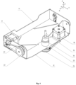
- the 3D printer comprises the following elements arranged within the body (Fig. 2): the print head 2 for supplying a thermoplastic material, the same print head being configured to move along the X-axis and/or along the Y-axis (including the possibility of moving within the X-Y plane).
- the device 1 comprises two motors 3 for feeding the material, the same motors being installed on the print head 2.
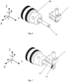
- the device also comprises two motors 4 and 5 for moving the head 2, as well as one guide 6 for moving the print head 2 along the X-axis and two guides 7 and 8 for moving the print head 2 along the Y-axis (Fig. 2 and 3 ).
- the guides 7 and 8 are arranged at the opposite sides of the print head 2 across the guide 6 ( Fig. 3 ).
- the claimed device 1 comprises the receiving surface 10 for receiving (winding, applying) of the material supplied from the print head 2 (Fig. 2-11).
- the receiving surface 10 is configured cylindrical.
- a rod can be used as the receiving surface 10, e.g., a rod can be used.
- the receiving surface is arranged within the unit 9 for accommodation of the receiving surface 10 (Fig. 2-5).
- Unit 9 is configured as the first and second connected structural elements 12 and 11, respectively, and is equipped with the Z-axis transfer device 13, the same axis being perpendicular to the X-Y plane.
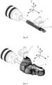
- the receiving surface 10 is arranged on the first structural element 12 to rotate about Z-axis and to be removable, e.g., while being placed within the grabbing device 19 which can be configured as a collet closing mechanism. That said, the element 12 can be configured, e.g., as a swing, and the transfer device 13 - as a carriage.
- Unit 9 comprises motor 14 and the two guides 15 and 16 for moving it along the Z-axis ( Fig. 3 ).
- the second structural element 11 is fixed on the transfer device 13 and movably connected to the first structural element 12 ( Fig. 4 5).
- the first structural element 12 is configured to rotate about the X-axis with the help of the motor 17 arranged on the second structural element 11.
- the receiving surface 10 is configured to rotate about the Z-axis with the help of the motor 18.
- the second structural element 11 comprises pulley 22 connected to the motor 17 with the help of the circular belt 23.
- the first structural element 12 comprises pulley 24 connected to the motor 18 with the help of the circular belt 25 ( Fig. 4 5).
- the claimed 3D printer may comprise a coil 20 with a consumable thermoplastic material. That said, the coil 20 with the consumable material can be arranged both inside and outside of the printer device 1 body (Fig. 2).
- the 3D printer may comprise the heating unit 21 used for heating the working volume of the device 1 ( Fig. 3 ) and the controller 29 for controlling the print head 2 movement.
- the increase of the obtained products' strength and the absence of an additional processing are achieved due to the fact that the claimed device, thanks to the print head 2 movement along the X-axis and the Y-axis and the receiving surface 10 accommodation unit 9 movement along the Z-axis, allows printing the product core with the shape repeating the product outlines; owing to the rotation about the X-axis, an automatic transfer from the product core printing to the product body printing is ensured; owing to the print head 2 movement along the Y-axis and the unit 9 movement along the Z-axis, as well as to the receiving surface 10 rotation about the Z-axis, a curved product body layers printing is ensured which allows producing strong products without additional processing.
- the claimed 3D objects additive production method utilizes a multi-stage printing process comprising the printing of the product core that does not protrude beyond the product body and repeats its shape, which allows producing products without an additional processing, and the printing of the product body which is produced in curved layers, which increases the product strength.
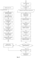
- the claimed method can be implemented in the following way (the block diagram is shown in Fig. 12 ).
- a digital 3D model of the produced object is formed on a personal computer using graphics software, e.g., Kompas 3D, Autodesk Inventor, Autodesk Fusion 360, SolidWorks, Blender, 3ds Max, Google SketchUp, the dimensions of the same 3D model corresponding to the printer parameters; the model is divided into the constituent parts which are separated in a layerwise manner into the flat and curved layers, respectively, and the construction data is prepared.
- graphics software e.g., Kompas 3D, Autodesk Inventor, Autodesk Fusion 360, SolidWorks, Blender, 3ds Max, Google SketchUp
- the formed model is loaded to the print preparation software that provides for the model division into the constituent parts (the product core and the product body), for the separation of these parts in a layerwise manner into the flat and curved layers, respectively (in the process, a layer is formed as a result of a surface (e.g., a cylindrical surface) intersecting with the product model, wherein each subsequent layer differs from the previous one by the layer thickness (for the rotary surfaces this is the distance between the moving line and the rotation axis, for the transition surfaces this is the offset along the construction vector)), and for the preparation and generation of the construction data (the movement sequence code), after which the construction data is sent to the controlling unit.
- a surface e.g., a cylindrical surface
- the intersecting surface can be any kinematic surface (ruled, non-ruled, rotary, cyclic, helical etc.)
- the common print settings are configured in the program: the print head 2 movement speed, the work piece cooling temperature (by controlling the product cooling fan mode of operation), the consumable material characteristics etc.
- the corresponding heater temperature for melting the plastic in the print head 2 is chosen, as well as the working chamber heating temperature for printing the product.
- the necessary parameters and conditions for the product parts (product core 28 and product body 30)' and auxiliary structures (the first part of the substrate 26, the second part of the substrate 27 and the supporting attachments)' printing are defined in the program.
- the product core 28 its dimensions (depending on the chosen cross-section surface), the flat printing layer thickness, the continuous outer shell thickness, the density of the internal filling of the core by the material (from 0 (for the hollow items production) to 100%) and the filling pattern parameters are determined.
- the software defines the shape of the core 28 as the result of the product' and the chosen cross-section surface' intersection. That said, if the chosen cross-section surface is a rotary surface (e.g., a cylindrical one), the lateral surface of the core 28 corresponds to the chosen cross-section surface with the specified core dimensions (the distance from the rotation axis to the moving line).
- the lower base of the core 28 corresponds to the lower product surface defined by the lateral surface of the core 28, and the upper base of the core 28 corresponds to the upper product surface defined by the lateral surface of the core 28.
- the curved printing layer thickness For the product body 30, the curved printing layer thickness, the continuous outer shell thickness, the density of the internal filling of the product by the material (from 0 (for the hollow items production) to 100%), the filling pattern parameters and the necessity of the supporting attachments' construction are specified.
- the filling pattern parameters are adjusted.
- the software automatically generates the dimensions of the first and second part of the substrate 26 and 27 based on the core 28 dimensions.
- the first part of the substrate 26 is designed for holding the product on the receiving surface 10.
- the second part of the substrate 27 is designed as the product core 28 initial construction plane.
- the supporting attachments For the supporting attachments, the density and the filling template parameters are specified.
- the supporting attachments can be built from the same material as the product, using the same print head nozzle.
- the supporting attachments can be built from another material, using the second nozzle.
- the software automatically generates the supporting attachments with a clearance relative to the printed product, to ensure its easy removal from the finished product surface.
- the software prepares the construction data represented as a computer command language, e.g., the g-code. For each flat and curved layer the software determines the outlines and then fills the layer based on the percentage value and the filling pattern chosen by the user. After the whole model is traversed, the supporting structures are built; then the construction data is exported to the prepared file.
- a computer command language e.g., the g-code
- the connection with the printer is established.
- the operability of all printer mechanical units is checked, as well as the availability of the installed consumable materials.
- the prepared task is loaded through a network interface or using a portable storage device.
- the controller starts the receiving surface 10' position change program module and sends the signal to the Z-axis transfer device 13 compelling it to go down as to avoid collision with the print head 2 and the signal to the unit 9 compelling it to change the position of the surface 10 to the vertical one (the axis of the rod is located in the plane that is parallel to the X-Z plane) - Fig. 8 .
- the production program module is started for the second part of the substrate 27 produced on the first part of the substrate 26 (based on the first part of the substrate 26).
- the controller starts the supporting attachments production program module (if required for the specific product) and then the product body 30 production program module ( Fig. 10 11).
- the product body 30 is produced by applying the material onto the core 28 in curved layers.
- Both product body 30 and the supporting attachments are produced in a layerwise manner in curved layers that boost the produced item strength(winding). The next layer is applied onto the previous one layer-by-layer until the product construction process is finished.
- a layer can have one or more parts. Each part includes one or more outlines, insets, skins and infill areas.
- a layer part is a separate area inside a layer that does not touch other parts.
- An outline is a nonprintable intersection of the model and of the intersection surface.
- Insets constitute a printable outline wall forming the shape of the product.
- Skins are printable surfaces that are 100% filled and form the shape of the product.
- the infill areas are the printable surfaces with a specified degree of filling that form the internal structure of the product.
- the number of walls can be set in the print preparation program; a value of 0 (the absence of walls) or more can be specified.
- the parameters of the filling density, the filling angle, the filling pattern and the filling overlap (the degree to which the beginning and end of the filling lines cross the internal outline insets) can be set up.
- the filling density can be specified in the print preparation program; a value from 0 (the absence of filling) up to 100% (solid filling) can be specified. That said, the filling density depends on the number of filling lines applied inside of the outline.
- the filling angle determines the angle between the filling line and the axis of ordinates of the layer surface coordinate frame.
- the value of 0 to 90 degrees can be specified. That said, the filling angle value can be varied from layer to layer, the set filling angle value being alternated with the value corresponding to the turn at the specified angle (equaling 90 degrees by default), for the formation of a net structure. By default, the accepted filling angle value equals 45 degrees.
- the method uses three variants of the curved filling pattern.
- the "spooling" variant of filling characterizes the continuity of the material feeding, when a sole filling line constitutes all the filling.
- the “winding” filling variant uses a helical filling curve. These methods are used for filling the layers formed by the rotary surfaces.
- the variant involving a line proceeding along a surface is generally used for filling the layers along any surfaces.
- the curved filling pattern sets the filling line appearance.
- the filling line constitutes a line on a curved layer surface, proceeding from the lower product surface to the upper product surface.
- the shape of the line depends on the filling pattern and can be curved, zigzagging or any other.
- Flat filling patterns are used for the production of the second part 27 of the substrate and of the product core 28.
- the used flat filling patterns are the same as those used during a regular 3D printing, known from the prior art.
Landscapes
- Chemical & Material Sciences (AREA)
- Engineering & Computer Science (AREA)
- Materials Engineering (AREA)
- Manufacturing & Machinery (AREA)
- Physics & Mathematics (AREA)
- Mechanical Engineering (AREA)
- Optics & Photonics (AREA)
Claims (12)
- Vorrichtung (1) zur additiven bzw. generativen Fertigung von 3D-Objekten, umfassend:- zumindest einen Druckkopf (2) zum Zuführen von Material, der konfiguriert ist, sich entlang einer X-Achse und/oder entlang einer Y-Achse zu bewegen;- zumindest eine Führung (6) zum Bewegen des Druckkopfs (2) entlang der X-Achse;- zumindest zwei Führungen (7, 8) zum Bewegen des Druckkopfs (2) entlang der Y-Achse, die konfiguriert sind, an den gegenüberliegenden bzw. entgegengesetzten Seiten des Druckkopfs (2) über zumindest eine Führung (6) zum Bewegen des Druckkopfs (2) entlang der X-Achse angeordnet zu sein;- eine Einheit (9), die eine zylindrisch geformte Aufnahmefläche bzw. - oberfläche (10) zum Aufnehmen des von dem Druckkopf (2) zugeführten Materials unterbringt,wobei die Einheit (9) zum Unterbringen der zylindrisch geformten Aufnahmefläche (10) ein erstes Strukturelement (12) umfasst und mit einer Transfervorrichtung (13) ausgestattet ist, die eine Bewegung entlang einer Z-Achse senkrecht zu der X-Y-Ebene bereitstellt, wobei das erste Strukturelement (12) konfiguriert ist, sich um die X-Achse zu drehen, und die zylindrisch geformte Aufnahmefläche (10) auf bzw. an dem ersten Strukturelement (12) angeordnet ist, um sich um die Z-Achse zu drehen,wobei die Vorrichtung (1) zusätzlich zumindest einen Motor (3) zum Zuführen des Materials und zumindest zwei Motoren (4, 5) zum Bewegen des Druckkopfs (2) umfasst,wobei die Einheit (9) zum Unterbringen der zylindrisch geformten Aufnahmefläche (10) zusätzlich zumindest ein zweites Strukturelement (11), das auf bzw. an der Transfervorrichtung (13) auf einer Seite fixiert bzw. befestigt und beweglich mit dem ersten Strukturelement (12) auf der gegenüberliegenden bzw. entgegengesetzten Seite verbunden ist, zumindest einen Motor (14) zum Bewegen entlang der Z-Achse, zumindest zwei Führungen (15, 16) zum Bewegen entlang der Z-Achse, zumindest einen Motor (17) zum Drehen des ersten Strukturelements (12) um die X-Achse und zumindest einen Motor (18) zum Drehen der zylindrisch geformten Aufnahmefläche (10) um die Z-Achse umfasst.
- Vorrichtung (1) nach Anspruch 1, wobei die Aufnahmefläche (10) abnehmbar angeordnet ist.
- Vorrichtung (1) nach Anspruch 2, wobei die Aufnahmefläche (10) in einer Greifvorrichtung (19) angeordnet ist.
- Vorrichtung (1) nach Anspruch 1, wobei die Vorrichtung (1) eine Spule (20) mit einem Verbrauchsmaterial umfasst.
- Vorrichtung (1) nach Anspruch 1, wobei die Vorrichtung (1) eine Heizeinheit (21) zum Heizen des Arbeitsvolumens der Vorrichtung (1) umfasst.
- Vorrichtung (1) nach Anspruch 1, wobei der Motor (17) zum Drehen des ersten Strukturelements (12) auf bzw. an dem zweiten Strukturelement (11) angeordnet ist.
- Vorrichtung nach Anspruch 1, wobei das zweite Strukturelement (11) eine Riemenscheibe bzw. Umlenkrolle (22) umfasst, die mittels eines Rundriemens (23) mit dem Motor (17) verbunden ist.
- Vorrichtung (1) nach Anspruch 7, wobei die Riemenscheibe (22) mit dem ersten Strukturelement (12) verbunden ist.
- Vorrichtung (1) nach Anspruch 1, wobei der Motor (18) zum Drehen der zylindrisch geformten Aufnahmefläche (10) auf bzw. an dem ersten Strukturelement (12) angeordnet ist.
- Vorrichtung (1) nach Anspruch 1, wobei das erste Strukturelement (12) eine Riemenscheibe bzw. Umlenkrolle (24) umfasst, die mittels eines Rundriemens (25) mit dem Motor (18) zum Drehen der zylindrisch geformten Aufnahmefläche (10) verbunden ist.
- Vorrichtung (1) nach Anspruch 1, wobei zumindest ein Motor (3) zum Zuführen des Materials auf bzw. an dem Druckkopf (2) angeordnet ist.
- Verfahren zur additiven bzw. generativen Fertigung von 3D-Objekten unter Verwendung der Vorrichtung (1) zur additiven bzw. generativen Fertigung von 3D-Objekten nach Anspruch 1, wobei das Verfahren die folgenden Schritte umfasst:a) Erzeugen eines digitalen 3D-Modells eines spezifizierten Objekts, Aufteilen des Modells auf einen Produktkern (28) und einen Produktkörper (30), schichtweises Trennen derselben in eine flache bzw. eine gekrümmte Schicht und Vorbereiten von Konstruktionsdaten;b) nachfolgendes Senden der Konstruktionsdaten an eine Steuer- bzw. Regeleinheit;c) Einstellen bzw. Anpassen einer Produktposition relativ zu der zylindrisch geformten Aufnahmefläche (10);d) Zuführen des erforderlichen Materials für den Prozess;e) Bestimmen von Nullkoordinaten für die Position des Druckkopfes (2) auf einer X-Achse, der Transfervorrichtung (13) auf einer Z-Achse und des ersten Strukturelements (12) um die X-Achse der Einheit (9) zum Unterbringen der zylindrisch geformten Aufnahmefläche (10);f) Bringen der zylindrisch geformten Aufnahmefläche (10) in eine horizontale Position, wobeig) ein erster Teil eines Substrats (26) und eine umhüllende laterale Fläche bzw. Oberfläche der zylindrisch geformten Aufnahmefläche (10) auf bzw. an der zylindrisch geformten Aufnahmefläche (10) gefertigt werden;h) Ändern der Position der zylindrisch geformten Aufnahmefläche (10) in eine vertikale Position;i) Fertigen eines zweiten Teils des Substrats (27) auf bzw. an dem ersten Teil des Substrats (26);j) Fertigen des Produktkerns (28) auf bzw. an dem zweiten Teil des Substrats (27);k) Ändern der Position der zylindrisch geformten Aufnahmefläche (10) in eine horizontale Position;l) Fertigen des Produktkörpers (30) durch Aufbringen des Materials auf den Kern (28) in gekrümmten bzw. gebogenen Schichten.
Applications Claiming Priority (2)
| Application Number | Priority Date | Filing Date | Title |
|---|---|---|---|
| RU2018144131A RU2717274C1 (ru) | 2019-03-11 | 2019-03-11 | Способ изготовления изделий с помощью аддитивных технологий и устройство для его осуществления |
| PCT/RU2020/050006 WO2020185122A1 (ru) | 2019-03-11 | 2020-01-24 | Пособ и устройство изготовления изделий с помощью аддититвных ехнологий |
Publications (3)
| Publication Number | Publication Date |
|---|---|
| EP3939773A1 EP3939773A1 (de) | 2022-01-19 |
| EP3939773A4 EP3939773A4 (de) | 2022-11-16 |
| EP3939773B1 true EP3939773B1 (de) | 2025-02-26 |
Family
ID=69898865
Family Applications (1)
| Application Number | Title | Priority Date | Filing Date |
|---|---|---|---|
| EP20768937.3A Active EP3939773B1 (de) | 2019-03-11 | 2020-01-24 | Verfahren und vorrichtung zur herstellung von artikeln durch additive fertigung |
Country Status (5)
| Country | Link |
|---|---|
| US (1) | US20220168962A1 (de) |
| EP (1) | EP3939773B1 (de) |
| CN (1) | CN113557123B (de) |
| RU (1) | RU2717274C1 (de) |
| WO (1) | WO2020185122A1 (de) |
Families Citing this family (5)
| Publication number | Priority date | Publication date | Assignee | Title |
|---|---|---|---|---|
| WO2023146547A1 (en) * | 2022-01-31 | 2023-08-03 | Hewlett-Packard Development Company, L.P. | Assistance structure for additive manufacturing |
| CN115648627B (zh) * | 2022-10-09 | 2025-11-18 | 苏州海明包装科技有限公司 | 一种提高产品良率的3d打印后处理装置及工艺 |
| EP4501591A1 (de) * | 2023-08-03 | 2025-02-05 | Technische Universität Berlin | Rotierende mehrachsige generative fertigungsvorrichtung |
| US12459202B2 (en) * | 2024-01-19 | 2025-11-04 | 3D Systems, Inc. | Flow rate control in extrusion deposition process |
| FR3163012A1 (fr) * | 2024-06-11 | 2025-12-12 | Compagnie Generale Des Etablissements Michelin | Dispositif de fabrication additive d’objets tridimensionnels |
Citations (1)
| Publication number | Priority date | Publication date | Assignee | Title |
|---|---|---|---|---|
| CN108773066A (zh) * | 2018-05-22 | 2018-11-09 | 张梦如 | 一种电场驱动熔融喷射沉积3d打印机 |
Family Cites Families (30)
| Publication number | Priority date | Publication date | Assignee | Title |
|---|---|---|---|---|
| CN102481729A (zh) * | 2009-07-29 | 2012-05-30 | 再德克斯私人有限公司 | 在旋转圆柱表面上的3d印刷 |
| US8920697B2 (en) | 2010-09-17 | 2014-12-30 | Stratasys, Inc. | Method for building three-dimensional objects in extrusion-based additive manufacturing systems using core-shell consumable filaments |
| EP2671706A1 (de) * | 2012-06-04 | 2013-12-11 | Ivoclar Vivadent AG | Verfahren zum Aufbau eines Formkörpers |
| FR2994113B1 (fr) * | 2012-07-31 | 2017-10-06 | Michelin & Cie | Machine et procede pour la fabrication additive a base de poudre |
| US9688028B2 (en) * | 2013-03-22 | 2017-06-27 | Markforged, Inc. | Multilayer fiber reinforcement design for 3D printing |
| SG2013056346A (en) * | 2013-06-25 | 2015-01-29 | Cal Comp Prec Singapore Ltd | Three-dimensional printing apparatus and printing method thereof |
| ITMI20131174A1 (it) * | 2013-07-12 | 2015-01-13 | Giovanni Grieco | Dispositivo a controllo numerico per la realizzazione di oggetti tridimensionali. |
| US20150102531A1 (en) * | 2013-10-11 | 2015-04-16 | Global Filtration Systems, A Dba Of Gulf Filtration Systems Inc. | Apparatus and method for forming three-dimensional objects using a curved build platform |
| US9808991B2 (en) * | 2014-07-29 | 2017-11-07 | Cc3D Llc. | Method and apparatus for additive mechanical growth of tubular structures |
| WO2016019435A1 (en) * | 2014-08-05 | 2016-02-11 | Laing O'rourke Australia Pty Limited | Apparatus for fabricating an object |
| CN105398053B (zh) * | 2014-08-26 | 2017-12-29 | 泰科电子(上海)有限公司 | 3d打印系统 |
| US20160096323A1 (en) | 2014-10-03 | 2016-04-07 | Tyco Electronics Corporation | Apparatus and method for rotary three-dimensional printing |
| US10442175B2 (en) | 2015-04-28 | 2019-10-15 | Warsaw Orthopedic, Inc. | 3D printing devices and methods |
| US9975322B2 (en) | 2016-02-23 | 2018-05-22 | Xerox Corporation | Method and device for building three-dimensional cylindrical objects |
| CN105618753A (zh) * | 2016-03-03 | 2016-06-01 | 中研智能装备有限公司 | 一种轧辊等离子3d打印再制造设备及再制造方法 |
| US10239157B2 (en) * | 2016-04-06 | 2019-03-26 | General Electric Company | Additive machine utilizing rotational build surface |
| CN205871201U (zh) * | 2016-06-28 | 2017-01-11 | 杭州铭展网络科技有限公司 | 一种用于圆筒壁成型的3d打印机 |
| CN106003728A (zh) * | 2016-06-28 | 2016-10-12 | 杭州铭展网络科技有限公司 | 用于圆筒壁成型的3d打印机 |
| JP2018001494A (ja) * | 2016-06-29 | 2018-01-11 | ローランドディー.ジー.株式会社 | 三次元造形装置および造形データ作成装置 |
| US10214002B2 (en) * | 2016-09-30 | 2019-02-26 | Xyzprinting, Inc. | Three dimensional printing apparatus and three dimensional printing method thereof |
| US10710302B2 (en) * | 2016-11-02 | 2020-07-14 | R3 Printing, Inc. | System and method for automated successive three-dimensional printing |
| CN206230889U (zh) * | 2016-12-09 | 2017-06-09 | 武汉市贝恩三维科技有限公司 | 一种可连续打印多个平台的物体的打印机 |
| US10906243B2 (en) | 2017-04-14 | 2021-02-02 | Elizabeth Silvestro | Additive lathe that prints in cylindrical coordinates |
| US20180296343A1 (en) * | 2017-04-18 | 2018-10-18 | Warsaw Orthopedic, Inc. | 3-d printing of porous implants |
| US20210213734A1 (en) * | 2017-04-21 | 2021-07-15 | Hewlett-Packard Development Company, L.P. | Printer service station |
| US11660196B2 (en) * | 2017-04-21 | 2023-05-30 | Warsaw Orthopedic, Inc. | 3-D printing of bone grafts |
| US20180345600A1 (en) * | 2017-05-31 | 2018-12-06 | General Electric Company | Method for real-time simultaneous additive and subtractive manufacturing with a dynamically grown build wall |
| US10703044B2 (en) * | 2017-07-27 | 2020-07-07 | Robert Bosch Tool Corporation | Removable build plate with evenly heated build surface of 3D printer |
| CN108189395A (zh) * | 2017-12-28 | 2018-06-22 | 宁波高新区方元三维科技有限公司 | 一种可调节角度的3d打印机 |
| RU186514U1 (ru) * | 2018-07-17 | 2019-01-22 | Общество с ограниченной ответственностью "ВОПЛОЩЕНИЕ" | 3d дельта-принтер |
-
2019
- 2019-03-11 RU RU2018144131A patent/RU2717274C1/ru active
-
2020
- 2020-01-24 CN CN202080020550.3A patent/CN113557123B/zh active Active
- 2020-01-24 US US17/436,051 patent/US20220168962A1/en not_active Abandoned
- 2020-01-24 WO PCT/RU2020/050006 patent/WO2020185122A1/ru not_active Ceased
- 2020-01-24 EP EP20768937.3A patent/EP3939773B1/de active Active
Patent Citations (1)
| Publication number | Priority date | Publication date | Assignee | Title |
|---|---|---|---|---|
| CN108773066A (zh) * | 2018-05-22 | 2018-11-09 | 张梦如 | 一种电场驱动熔融喷射沉积3d打印机 |
Also Published As
| Publication number | Publication date |
|---|---|
| US20220168962A1 (en) | 2022-06-02 |
| RU2717274C1 (ru) | 2020-03-19 |
| EP3939773A1 (de) | 2022-01-19 |
| CN113557123A (zh) | 2021-10-26 |
| EP3939773A4 (de) | 2022-11-16 |
| WO2020185122A1 (ru) | 2020-09-17 |
| CN113557123B (zh) | 2024-03-01 |
Similar Documents
| Publication | Publication Date | Title |
|---|---|---|
| EP3939773B1 (de) | Verfahren und vorrichtung zur herstellung von artikeln durch additive fertigung | |
| JP6868657B2 (ja) | 繊維強化加法的製造の方法 | |
| EP3442775B1 (de) | Optimiertes dreidimensionales drucken unter verwendung vorgefertigter träger | |
| US20160067740A1 (en) | Three dimensional (3d) printer with a build plate having multi-degree of freedom motion | |
| EP3345743B1 (de) | Verfahren zum dreidimensionalen drucken und vorrichtung zum dreidimensionalen drucken | |
| US9694544B2 (en) | Methods for fiber reinforced additive manufacturing | |
| US6934600B2 (en) | Nanotube fiber reinforced composite materials and method of producing fiber reinforced composites | |
| EP3023237B1 (de) | Verfahren und Vorrichtung zur Herstellung eines dreidimensionalen Objekts mittels Additivherstellung | |
| US12115726B2 (en) | Systems and methods for printing components using additive manufacturing | |
| US10682821B2 (en) | Flexible tooling system and method for manufacturing of composite structures | |
| WO2017110375A1 (ja) | 三次元加工装置 | |
| KR101692141B1 (ko) | 삼차원 구조물 제조장치 및 방법 | |
| CN116529086A (zh) | 使用机器人的三维打印机和机器人的控制装置 | |
| JP7664937B2 (ja) | ボートの型を積層造形によって製造する方法及びシステム | |
| Castelli et al. | A preliminary 6 Dofs robot based setup for fused deposition modeling | |
| WO2019112453A1 (en) | Method for producing three-dimensional objects | |
| US12436520B2 (en) | Method and system of three-dimensional printing to prepare surface for gripping of subsequent layers | |
| CA2204792A1 (en) | Apparatus and method for constructing and sculpting shapes | |
| JP2024003384A (ja) | 情報処理装置 | |
| HK40055771A (en) | Methods for fiber reinforced additive manufacturing | |
| CN116133828A (zh) | 用于基于激光的增材制造的系统和方法 |
Legal Events
| Date | Code | Title | Description |
|---|---|---|---|
| STAA | Information on the status of an ep patent application or granted ep patent |
Free format text: STATUS: THE INTERNATIONAL PUBLICATION HAS BEEN MADE |
|
| PUAI | Public reference made under article 153(3) epc to a published international application that has entered the european phase |
Free format text: ORIGINAL CODE: 0009012 |
|
| STAA | Information on the status of an ep patent application or granted ep patent |
Free format text: STATUS: REQUEST FOR EXAMINATION WAS MADE |
|
| 17P | Request for examination filed |
Effective date: 20210913 |
|
| AK | Designated contracting states |
Kind code of ref document: A1 Designated state(s): AL AT BE BG CH CY CZ DE DK EE ES FI FR GB GR HR HU IE IS IT LI LT LU LV MC MK MT NL NO PL PT RO RS SE SI SK SM TR |
|
| DAV | Request for validation of the european patent (deleted) | ||
| DAX | Request for extension of the european patent (deleted) | ||
| A4 | Supplementary search report drawn up and despatched |
Effective date: 20221014 |
|
| RIC1 | Information provided on ipc code assigned before grant |
Ipc: B29C 64/393 20170101ALI20221011BHEP Ipc: B33Y 10/00 20150101ALI20221011BHEP Ipc: B33Y 30/00 20150101ALI20221011BHEP Ipc: B29C 64/245 20170101ALI20221011BHEP Ipc: B29C 64/236 20170101ALI20221011BHEP Ipc: B29C 64/232 20170101ALI20221011BHEP Ipc: B29C 64/118 20170101AFI20221011BHEP |
|
| STAA | Information on the status of an ep patent application or granted ep patent |
Free format text: STATUS: EXAMINATION IS IN PROGRESS |
|
| 17Q | First examination report despatched |
Effective date: 20231004 |
|
| GRAP | Despatch of communication of intention to grant a patent |
Free format text: ORIGINAL CODE: EPIDOSNIGR1 |
|
| STAA | Information on the status of an ep patent application or granted ep patent |
Free format text: STATUS: GRANT OF PATENT IS INTENDED |
|
| INTG | Intention to grant announced |
Effective date: 20240610 |
|
| GRAS | Grant fee paid |
Free format text: ORIGINAL CODE: EPIDOSNIGR3 |
|
| GRAA | (expected) grant |
Free format text: ORIGINAL CODE: 0009210 |
|
| STAA | Information on the status of an ep patent application or granted ep patent |
Free format text: STATUS: THE PATENT HAS BEEN GRANTED |
|
| PUAC | Information related to the publication of a b1 document modified or deleted |
Free format text: ORIGINAL CODE: 0009299EPPU |
|
| STAA | Information on the status of an ep patent application or granted ep patent |
Free format text: STATUS: GRANT OF PATENT IS INTENDED |
|
| AK | Designated contracting states |
Kind code of ref document: B1 Designated state(s): AL AT BE BG CH CY CZ DE DK EE ES FI FR GB GR HR HU IE IS IT LI LT LU LV MC MK MT NL NO PL PT RO RS SE SI SK SM TR |
|
| RAP3 | Party data changed (applicant data changed or rights of an application transferred) |
Owner name: STEREOTECH LIMITED LIABILITY COMPANY |
|
| REG | Reference to a national code |
Ref country code: GB Ref legal event code: FG4D |
|
| REG | Reference to a national code |
Ref country code: CH Ref legal event code: PK Free format text: DIE ERTEILUNG WURDE VOM EPA WIDERRUFEN. Ref country code: CH Ref legal event code: EP |
|
| REG | Reference to a national code |
Ref country code: IE Ref legal event code: FG4D |
|
| REG | Reference to a national code |
Ref country code: DE Ref legal event code: R096 Ref document number: 602020041347 Country of ref document: DE |
|
| DB1 | Publication of patent cancelled |
Effective date: 20241107 |
|
| REG | Reference to a national code |
Ref country code: DE Ref legal event code: R107 Ref country code: DE Ref legal event code: R107 Ref document number: 602020041347 Country of ref document: DE |
|
| PG25 | Lapsed in a contracting state [announced via postgrant information from national office to epo] |
Ref country code: FR Free format text: LAPSE BECAUSE OF NON-PAYMENT OF DUE FEES Effective date: 20241113 |
|
| GRAA | (expected) grant |
Free format text: ORIGINAL CODE: 0009210 |
|
| STAA | Information on the status of an ep patent application or granted ep patent |
Free format text: STATUS: THE PATENT HAS BEEN GRANTED |
|
| AK | Designated contracting states |
Kind code of ref document: B1 Designated state(s): AL AT BE BG CH CY CZ DE DK EE ES FI FR GB GR HR HU IE IS IT LI LT LU LV MC MK MT NL NO PL PT RO RS SE SI SK SM TR |
|
| REG | Reference to a national code |
Ref country code: CH Ref legal event code: EP |
|
| PG25 | Lapsed in a contracting state [announced via postgrant information from national office to epo] |
Ref country code: IS Free format text: LAPSE BECAUSE OF FAILURE TO SUBMIT A TRANSLATION OF THE DESCRIPTION OR TO PAY THE FEE WITHIN THE PRESCRIBED TIME-LIMIT Effective date: 20250313 |
|
| REG | Reference to a national code |
Ref country code: DE Ref legal event code: R096 Ref document number: 602020041347 Country of ref document: DE |
|
| REG | Reference to a national code |
Ref country code: NL Ref legal event code: MP Effective date: 20250226 |
|
| PG25 | Lapsed in a contracting state [announced via postgrant information from national office to epo] |
Ref country code: FI Free format text: LAPSE BECAUSE OF FAILURE TO SUBMIT A TRANSLATION OF THE DESCRIPTION OR TO PAY THE FEE WITHIN THE PRESCRIBED TIME-LIMIT Effective date: 20250226 |
|
| PG25 | Lapsed in a contracting state [announced via postgrant information from national office to epo] |
Ref country code: PL Free format text: LAPSE BECAUSE OF FAILURE TO SUBMIT A TRANSLATION OF THE DESCRIPTION OR TO PAY THE FEE WITHIN THE PRESCRIBED TIME-LIMIT Effective date: 20250226 |
|
| PG25 | Lapsed in a contracting state [announced via postgrant information from national office to epo] |
Ref country code: ES Free format text: LAPSE BECAUSE OF FAILURE TO SUBMIT A TRANSLATION OF THE DESCRIPTION OR TO PAY THE FEE WITHIN THE PRESCRIBED TIME-LIMIT Effective date: 20250226 |
|
| REG | Reference to a national code |
Ref country code: LT Ref legal event code: MG9D |
|
| PG25 | Lapsed in a contracting state [announced via postgrant information from national office to epo] |
Ref country code: NO Free format text: LAPSE BECAUSE OF FAILURE TO SUBMIT A TRANSLATION OF THE DESCRIPTION OR TO PAY THE FEE WITHIN THE PRESCRIBED TIME-LIMIT Effective date: 20250526 |
|
| PG25 | Lapsed in a contracting state [announced via postgrant information from national office to epo] |
Ref country code: NL Free format text: LAPSE BECAUSE OF FAILURE TO SUBMIT A TRANSLATION OF THE DESCRIPTION OR TO PAY THE FEE WITHIN THE PRESCRIBED TIME-LIMIT Effective date: 20250226 |
|
| PG25 | Lapsed in a contracting state [announced via postgrant information from national office to epo] |
Ref country code: HR Free format text: LAPSE BECAUSE OF FAILURE TO SUBMIT A TRANSLATION OF THE DESCRIPTION OR TO PAY THE FEE WITHIN THE PRESCRIBED TIME-LIMIT Effective date: 20250226 |
|
| PG25 | Lapsed in a contracting state [announced via postgrant information from national office to epo] |
Ref country code: PT Free format text: LAPSE BECAUSE OF FAILURE TO SUBMIT A TRANSLATION OF THE DESCRIPTION OR TO PAY THE FEE WITHIN THE PRESCRIBED TIME-LIMIT Effective date: 20250626 Ref country code: LV Free format text: LAPSE BECAUSE OF FAILURE TO SUBMIT A TRANSLATION OF THE DESCRIPTION OR TO PAY THE FEE WITHIN THE PRESCRIBED TIME-LIMIT Effective date: 20250226 |
|
| PG25 | Lapsed in a contracting state [announced via postgrant information from national office to epo] |
Ref country code: BG Free format text: LAPSE BECAUSE OF FAILURE TO SUBMIT A TRANSLATION OF THE DESCRIPTION OR TO PAY THE FEE WITHIN THE PRESCRIBED TIME-LIMIT Effective date: 20250226 |
|
| REG | Reference to a national code |
Ref country code: AT Ref legal event code: MK05 Ref document number: 1741372 Country of ref document: AT Kind code of ref document: T Effective date: 20250226 |
|
| PG25 | Lapsed in a contracting state [announced via postgrant information from national office to epo] |
Ref country code: SK Free format text: LAPSE BECAUSE OF FAILURE TO SUBMIT A TRANSLATION OF THE DESCRIPTION OR TO PAY THE FEE WITHIN THE PRESCRIBED TIME-LIMIT Effective date: 20250226 |
|
| PG25 | Lapsed in a contracting state [announced via postgrant information from national office to epo] |
Ref country code: SM Free format text: LAPSE BECAUSE OF FAILURE TO SUBMIT A TRANSLATION OF THE DESCRIPTION OR TO PAY THE FEE WITHIN THE PRESCRIBED TIME-LIMIT Effective date: 20250226 |
|
| PG25 | Lapsed in a contracting state [announced via postgrant information from national office to epo] |
Ref country code: DK Free format text: LAPSE BECAUSE OF FAILURE TO SUBMIT A TRANSLATION OF THE DESCRIPTION OR TO PAY THE FEE WITHIN THE PRESCRIBED TIME-LIMIT Effective date: 20250226 |
|
| PG25 | Lapsed in a contracting state [announced via postgrant information from national office to epo] |
Ref country code: IT Free format text: LAPSE BECAUSE OF FAILURE TO SUBMIT A TRANSLATION OF THE DESCRIPTION OR TO PAY THE FEE WITHIN THE PRESCRIBED TIME-LIMIT Effective date: 20250226 |
|
| PG25 | Lapsed in a contracting state [announced via postgrant information from national office to epo] |
Ref country code: AT Free format text: LAPSE BECAUSE OF FAILURE TO SUBMIT A TRANSLATION OF THE DESCRIPTION OR TO PAY THE FEE WITHIN THE PRESCRIBED TIME-LIMIT Effective date: 20250226 |
|
| PG25 | Lapsed in a contracting state [announced via postgrant information from national office to epo] |
Ref country code: CZ Free format text: LAPSE BECAUSE OF FAILURE TO SUBMIT A TRANSLATION OF THE DESCRIPTION OR TO PAY THE FEE WITHIN THE PRESCRIBED TIME-LIMIT Effective date: 20250226 |
|
| PG25 | Lapsed in a contracting state [announced via postgrant information from national office to epo] |
Ref country code: RO Free format text: LAPSE BECAUSE OF FAILURE TO SUBMIT A TRANSLATION OF THE DESCRIPTION OR TO PAY THE FEE WITHIN THE PRESCRIBED TIME-LIMIT Effective date: 20250226 |
|
| REG | Reference to a national code |
Ref country code: DE Ref legal event code: R097 Ref document number: 602020041347 Country of ref document: DE |
|
| PLBE | No opposition filed within time limit |
Free format text: ORIGINAL CODE: 0009261 |
|
| STAA | Information on the status of an ep patent application or granted ep patent |
Free format text: STATUS: NO OPPOSITION FILED WITHIN TIME LIMIT |
|
| 26N | No opposition filed |
Effective date: 20251127 |