EP3939422B1 - (aqua-)terrarium - Google Patents
(aqua-)terrarium Download PDFInfo
- Publication number
- EP3939422B1 EP3939422B1 EP21185099.5A EP21185099A EP3939422B1 EP 3939422 B1 EP3939422 B1 EP 3939422B1 EP 21185099 A EP21185099 A EP 21185099A EP 3939422 B1 EP3939422 B1 EP 3939422B1
- Authority
- EP
- European Patent Office
- Prior art keywords
- container
- terrarium
- aqua
- electrothermal converter
- loop
- Prior art date
- Legal status (The legal status is an assumption and is not a legal conclusion. Google has not performed a legal analysis and makes no representation as to the accuracy of the status listed.)
- Active
Links
Images

Classifications
-
- A—HUMAN NECESSITIES
- A01—AGRICULTURE; FORESTRY; ANIMAL HUSBANDRY; HUNTING; TRAPPING; FISHING
- A01K—ANIMAL HUSBANDRY; AVICULTURE; APICULTURE; PISCICULTURE; FISHING; REARING OR BREEDING ANIMALS, NOT OTHERWISE PROVIDED FOR; NEW BREEDS OF ANIMALS
- A01K67/00—Rearing or breeding animals, not otherwise provided for; New or modified breeds of animals
- A01K67/02—Breeding vertebrates
-
- A—HUMAN NECESSITIES
- A01—AGRICULTURE; FORESTRY; ANIMAL HUSBANDRY; HUNTING; TRAPPING; FISHING
- A01K—ANIMAL HUSBANDRY; AVICULTURE; APICULTURE; PISCICULTURE; FISHING; REARING OR BREEDING ANIMALS, NOT OTHERWISE PROVIDED FOR; NEW BREEDS OF ANIMALS
- A01K63/00—Receptacles for live fish, e.g. aquaria; Terraria
- A01K63/003—Aquaria; Terraria
-
- A—HUMAN NECESSITIES
- A01—AGRICULTURE; FORESTRY; ANIMAL HUSBANDRY; HUNTING; TRAPPING; FISHING
- A01G—HORTICULTURE; CULTIVATION OF VEGETABLES, FLOWERS, RICE, FRUIT, VINES, HOPS OR SEAWEED; FORESTRY; WATERING
- A01G9/00—Cultivation in receptacles, forcing-frames or greenhouses; Edging for beds, lawn or the like
- A01G9/14—Greenhouses
- A01G9/16—Dismountable or portable greenhouses ; Greenhouses with sliding roofs
-
- A—HUMAN NECESSITIES
- A01—AGRICULTURE; FORESTRY; ANIMAL HUSBANDRY; HUNTING; TRAPPING; FISHING
- A01G—HORTICULTURE; CULTIVATION OF VEGETABLES, FLOWERS, RICE, FRUIT, VINES, HOPS OR SEAWEED; FORESTRY; WATERING
- A01G9/00—Cultivation in receptacles, forcing-frames or greenhouses; Edging for beds, lawn or the like
- A01G9/24—Devices or systems for heating, ventilating, regulating temperature, illuminating, or watering, in greenhouses, forcing-frames, or the like
- A01G9/247—Watering arrangements
-
- A—HUMAN NECESSITIES
- A01—AGRICULTURE; FORESTRY; ANIMAL HUSBANDRY; HUNTING; TRAPPING; FISHING
- A01K—ANIMAL HUSBANDRY; AVICULTURE; APICULTURE; PISCICULTURE; FISHING; REARING OR BREEDING ANIMALS, NOT OTHERWISE PROVIDED FOR; NEW BREEDS OF ANIMALS
- A01K63/00—Receptacles for live fish, e.g. aquaria; Terraria
- A01K63/06—Arrangements for heating or lighting in, or attached to, receptacles for live fish
- A01K63/065—Heating or cooling devices
Definitions
- the invention relates to a terrarium or aquaterrarium, in particular for ectothermic animals, with a container serving as a habitat.
- Terrariums and aquaterrariums are vivariums for keeping various, particularly exotic animals and/or plants.
- the habitat is a container that is at least partially visible and in which a piece of land, i.e. a piece of ground that can be walked on or planted, can be set up. They are called terrariums if the land portion and/or air space predominates in the fully furnished vivarium. On the other hand, they are called aquaterrariums if the water portion predominates.
- the aim is usually to recreate the natural habitat of the species to be kept as closely as possible, with a focus on creating suitable climatic conditions - such as temperature, humidity and/or lighting conditions.
- suitable climatic conditions such as temperature, humidity and/or lighting conditions.
- Adequate temperature management is particularly essential when keeping ectothermic animals such as reptiles, which, unlike mammals, do not produce their own body heat and are dependent on external sources of heat or cold to regulate their body temperature. Otherwise, hypothermia or overheating can lead to illness in the animals.
- the object of the present invention is therefore to provide an improved possibility for regulating the climatic conditions of an (aqua)terrarium, which comprises at least a temperature regulation.
- the (aqua)terrarium according to the invention is characterized by an air conditioning device which comprises a flow machine, preferably a fan, and an electrothermal converter, in particular a Peltier element.
- the air conditioning device sucks air out of the container, conditions the sucked-in air by guiding it along a first side of the electrothermal converter and conveys the conditioned air back into the Container.
- the temperature is thus regulated at least in part by conditioning a circulating air flow.
- the thermoelectric converter serving as a source of heat and/or cold does not have to be placed directly in the container or pointed at the container, which reduces the risk of injury from heat/cold peaks or direct contact.
- heat lamps and/or heating wires can be dispensed with entirely. If heat lamps and/or heating wires are nevertheless used as a support, they can be made smaller and/or positioned at a greater distance, e.g. in inaccessible areas of the (aqua)terrarium.
- the flow machine generates a forced air flow that guides the air along the first side of the electrothermal converter.
- the electrothermal converter can be easily controlled according to the respective requirements. By applying a voltage to the two contacts of the electrothermal converter, usually a direct voltage, the first side becomes hot, for example, and the air guided along it is heated. By simply reversing the direction of the current, the system switches from heating to cooling mode. The first side of the converter becomes cold and cools the air guided along it.
- the electrothermal converter is located outside the container. This further reduces the risk of injury from heat/cold peaks or direct contact. In this case, the air flow generated by the flow machine leads out of the container, along the electrothermal converter for conditioning purposes and then back into the
- the electrothermal converter is preferably arranged behind one of the walls of the container delimiting the living space, preferably a rear wall that cannot be seen.
- the turbomachine is arranged outside the container, preferably behind one of the walls of the container that delimit the living space, preferably a rear wall that cannot be seen. In this way, the risk of injury is counteracted, since there are no moving parts of the turbomachine inside the container.
- At least the first side of the electrothermal converter is arranged at right angles to a nearest wall of the container that delimits the living space, in particular a side or rear wall.
- the first side is not directed directly at the wall, so that it is not heated too much in heating mode, for example, which could otherwise lead to injuries if the wall is touched.
- the nearest wall to the electrothermal converter is the wall that is the smallest distance from the converter, e.g. a side or rear wall behind which the converter is arranged.
- the nearest wall can also be a floor or a ceiling of the container.
- the air conditioning device has an air duct which extends at least partially, preferably completely, outside the container, wherein the first side of the electrothermal converter or a thermally conductively connected to the first side Heat sink forms part of the wall of the air duct.
- the first side of the electrothermal converter preferably has a heat sink, e.g. in the form of an attachment with cooling fins, which protrudes into the air duct. By using cooling fins, for example, the surface of the first side of the electrothermal converter is increased, whereby the air is conditioned more efficiently.
- the air duct is designed such that at least in a section of the air duct in which the electrothermal converter or a heat sink thermally conductively connected to its first side is located, a wall of the air duct does not touch the nearest wall of the container, for example a rear wall of the container. In this way, an even better thermal separation between the heat/cold source and the container is achieved, thus further reducing the risk of injuries, for example from heat/cold peaks or direct contact.
- the air conditioning system has an inlet opening and an outlet opening towards the container, the inlet opening being arranged in a lower region of the container and the outlet opening in an upper region of the container.
- optimal circulation of the air can be achieved.
- a temperature gradient along a vertical can be created in this way, so that ectothermic animals in particular can regulate their body temperature by seeking out a certain altitude in an appropriately set up (aqua) terrarium. For example, warmer temperatures can be generated in the upper region and lower temperatures in the lower region of the container.
- the upper region of the container is referred to as an upper half, in particular an upper third, preferably an upper quarter, of the container in relation to the total height of the container.
- the lower region of the container is referred to as a lower half, in particular a lower third, preferably a lower quarter, of the container in relation to the total height of the container.
- the lower region and the upper region are not related to the total height of the container, but to a height shortened by a water level within the container, e.g. an air space height.
- the inlet opening is preferably arranged above the substrate forming a piece of land in the container or a water level.
- both the inlet opening and the outlet opening are arranged on a single side or rear wall of the container.
- the air conditioning device has a heat dissipation channel that runs outside the container, with a second side of the electrothermal converter, which is opposite the first side of the electrothermal converter, or an exhaust air cooling body thermally connected to the second side forming part of the wall of the exhaust air channel.
- the waste heat that is generated on the second side of the electrothermal converter can be optimally dissipated into the environment.
- the electrothermal converter is also arranged at right angles to a nearby wall, neither its first nor its second side is directed directly at the wall, which counteracts heating up or cooling down of the wall.
- the heat dissipation duct is equipped with its own flow machine, which generates a forced exhaust air flow and thus improves heat dissipation.
- the second side of the electrothermal converter has an exhaust air heat sink, e.g. in the form of an attachment with cooling fins that protrudes into the heat exhaust air duct.
- This increases the surface area of the second side of the electrothermal converter, allowing the heat to be released into the exhaust air more efficiently.
- the (aqua) terrarium has a control and regulation unit that is connected to at least one temperature sensor in a data-transmitting manner and regulates the flow machine and/or the electrothermal converter.
- a control and regulation unit that is connected to at least one temperature sensor in a data-transmitting manner and regulates the flow machine and/or the electrothermal converter.
- control and regulating unit is connected to at least one humidity sensor in a data-transmitting manner, wherein the control and regulating unit regulates a nebulizer of the air conditioning device, in particular an ultrasonic nebulizer, with which Water from a water reservoir of the air conditioning device can be nebulized and released into the container to increase the humidity.
- a nebulizer of the air conditioning device in particular an ultrasonic nebulizer, with which Water from a water reservoir of the air conditioning device can be nebulized and released into the container to increase the humidity.
- the air conditioning device according to the invention can be combined with a nebulization system without any safety concerns, whereby the climate in the (aqua) terrarium can be regulated to a greater extent and the natural habitat of the species to be kept can be reproduced even better.
- the control and regulation unit is connected in a data-transmitting manner to at least a first sensor, which is designed at least as a temperature sensor, and a second sensor, which is designed at least as a temperature sensor, wherein the first sensor is arranged in an upper region of the container and the second sensor is arranged in a lower region of the container.
- a temperature gradient can be measured along a vertical line and used for improved regulation of at least the turbomachine and/or the electrothermal converter.
- the first sensor is arranged substantially at the level of or above the outlet opening.
- the second sensor is arranged below or substantially at the level of the inlet opening of the air conditioning device.
- control and regulation unit is set up in such a way that - in particular depending on the animal to be kept - a pre-programmed parameter configuration of climate-specific target values/value ranges can be selected, which includes at least one target temperature, preferably a target temperature range.
- a keeper can quickly set an optimal climate in the (aqua) terrarium for his animal. To do this, he only has to select the desired climate for the respective animal. or select a suitable program.
- a selection of programs is provided, whereby the parameter configuration of each program is tailored to a specific biome or corresponds to a specific biome that represents a natural habitat for one or more animals to be kept. Since this minimizes the risk of incorrect settings and the resulting overheating or hypothermia, such an (aqua) terrarium is particularly suitable for laypeople.
- the climate-specific target values/value ranges also include specifications for air humidity, which can be used, for example, to control a fogging system.
- the air conditioning device comprises further systems for influencing or simulating further climate elements and/or conditions of the natural habitat of a species to be kept, such as floor heating to support temperature regulation, an irrigation system, a lighting or irradiation system (e.g. white lights, RGB lights and/or UV/IR lamps) and/or at least one loudspeaker to imitate a natural acoustic environment.
- the control and regulation unit is preferably designed to regulate at least one of these systems, in particular with a pre-programmed parameter configuration comprising corresponding climate-specific target values, e.g. irrigation intervals, lighting intervals/intensities and/or assigned audio files.
- control and regulation unit can be controlled via an app running on a data processing system, e.g. a home computer, a laptop, a tablet and/or a smartphone.
- a data processing system e.g. a home computer, a laptop, a tablet and/or a smartphone.
- the present invention provides an (aqua) terrarium in which improved regulation of the climatic conditions in the container is achieved, in particular automated and tailored to the respective animal to be kept. At least one temperature or one temperature gradient is influenced.
- a natural habitat is imitated to a particularly high degree by optionally also controlling air humidity, irrigation, lighting and/or an acoustic environment.
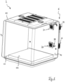
- FIGS. 1 to 4a show various (partial) views of a terrarium 2 according to the invention with a substantially cubically shaped container 4, which is designed as a habitat in particular for ectothermic animals.
- the habitat is delimited by three adjacent transparent side walls, a rear wall 14, a lid 16 and a base 18.
- the terrarium 2 is equipped with an air conditioning device 6, which in the embodiment shown is arranged mostly behind the rear wall 14 and in the Fig.3 , 4 and 4a is shown in more detail.
- the air conditioning device 6 has a flow machine 8 (e.g. a fan) and an electrothermal converter 10, for example in the form of a Peltier element.
- a flow machine 8 e.g. a fan
- an electrothermal converter 10 for example in the form of a Peltier element.
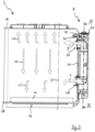
- the air conditioning device 6 sucks air from the container 4 into an air duct 22 via an inlet opening 20 let into the rear wall 14.
- the sucked-in air 7 is guided along a first side 12 of the electrothermal converter 10 within the air duct 22 and conditioned by it, i.e. heated or cooled depending on the operating mode (heating or cooling mode).
- the conditioned air 9 is conveyed back into the container 4 via an outlet opening 24 let into the rear wall.
- warmer air 11 rises, while colder air 13, 13' sinks.
- a temperature gradient is created along a vertical V.
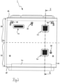
- the inlet opening 20 is arranged in a lower region 26 and the outlet opening 24 in an upper region 28 of the container 4.
- the lower region 26 of the container 4 comprises the lower half of the container 4 in relation to a total height H of the container 4.
- the upper region 28 comprises the upper half of the container in relation to its total height H.
- the lower region 26 and the upper region 28 can not be related to the total height H of the container 4, but to a height shortened by a water level within the container 4, e.g. an air space height.
- the first side 12 is provided with a heat sink 12a in the form of a thermally conductive attachment with cooling fins.
- This heat sink 12a forms part of the wall of the air channel 22, with its side facing the electrothermal converter 10 closing off the air channel 22. This enables efficient conditioning of the air while requiring little installation space.
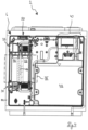
- the air conditioning device 6 In cooling mode, i.e. when current flows through the electrothermal converter 10 in such a way that the first side 12 becomes cold, heat is generated on a second side 30 of the electrothermal converter 10, which is opposite its first side 12.
- the air conditioning device 6 has a heat dissipation air duct 32 that runs outside the container 4.
- the second side 30 of the electrothermal converter 10 forms part of the wall of the heat dissipation air duct 32.
- the second side 30 has an exhaust air heat sink 30a in the form of an attachment with cooling fins that protrudes into the heat dissipation air duct 32.
- An exhaust air flow machine 34 for example in the form of a fan, generates an exhaust air flow that supports the heat dissipation.
- An exhaust air inlet opening 35 and an exhaust air outlet opening 37 of the heat exhaust air duct 32 are not open towards the container 4, but suck in air from the environment and release it back into the environment.
- the electrothermal converter 10 which in the present embodiment is essentially plate-shaped, is arranged at a right angle to the rear wall 14, which represents a nearest wall of the terrarium 2.
- the first side 12 nor the second side 30 of the electrothermal converter 10 are directed directly at the rear wall 14, so that the latter is not heated too much in heating mode by the first side 12 (heating heat) nor in cooling mode by the second side 30 (waste heat).
- the special arrangement of the electrothermal converter Converter 10 between the air duct 22 and the heat dissipation air duct 32 which run parallel to each other at least in their respective sections in which part of their wall is formed by the electrothermal converter 10, optimally transports away both the cold and the heat in any operating mode. This is further enhanced by the heat sinks 12a, 30 used.
- the terrarium 2 has a control and regulation unit (not shown in detail in the drawings) which is connected to a first sensor 36 and a second sensor 38 for data transmission.
- the first sensor 36 is arranged in an upper area 28 of the container, while the second sensor 38 is arranged in a lower area 26 of the container 4.
- Both sensors 36, 38 are designed as 2-in-1 combination sensors for measuring both the temperature and the humidity. This allows the climate in the terrarium 2 to be regulated to a greater extent and thus the natural habitat of the species to be kept can be reproduced even better.
- the control and regulation unit regulates the flow machine 8 and the thermoelectric converter 6, whereby a target value or a target value range can be specified for the control and regulation unit.
- a target-actual comparison of the predetermined target values with actual values recorded within the container 4 by at least one of the sensors 36, 38 can serve as a decision criterion for controlling the electrothermal converter 6 and/or the flow machine 8.
- control and regulation unit further controls a nebulizer 40, with which water from a water reservoir 42 can be nebulized. and can be released into the container 4 via a nebulizer opening 44 to increase the air humidity.
- the control and regulation unit is set up in such a way that, depending on the animal to be kept, a pre-programmed parameter configuration of climate-specific target values can be selected, which includes at least one target temperature.
- a pre-programmed parameter configuration of climate-specific target values can be selected, which includes at least one target temperature.
- the biome to be simulated for the respective animal species can be selected using a smartphone or another data processing system via an app, for example.
- a parameter configuration is assigned to the selected biome, so that the control and regulation unit controls the air conditioning device 6 and can thus optimally adapt the climatic conditions in the terrarium 2 to the natural habitat of the animal to be kept.
- control and regulation unit can also be combined with other systems of the air conditioning device 6.
- the control and regulation unit regulates a floor heating 46 thermally connected to a base plate 44 of the container for supporting temperature regulation, a sprinkling system which comprises two sprinkling nozzles 48 arranged in the upper region 28 of the container 4, and a loudspeaker 50 for imitating a natural acoustic environment.
Landscapes
- Life Sciences & Earth Sciences (AREA)
- Environmental Sciences (AREA)
- Animal Husbandry (AREA)
- Biodiversity & Conservation Biology (AREA)
- Marine Sciences & Fisheries (AREA)
- Zoology (AREA)
- Animal Behavior & Ethology (AREA)
- Housing For Livestock And Birds (AREA)
- Farming Of Fish And Shellfish (AREA)
Description
- Die Erfindung betrifft ein Terrarium oder Aquaterrarium, insbesondere für ektotherme Tiere, mit einem als Lebensraum dienenden Behältnis.
- Terrarien sowie Aquaterrarien sind Vivarien zur Haltung verschiedener, insbesondere exotischer Tiere und/oder Pflanzen. Als Lebensraum dient dabei ein zumindest bereichsweise einsehbares Behältnis, in dem ein Stück Land, d.h. ein Stück begehbar oder bepflanzbarer Boden, eingerichtet werden kann. Man spricht von Terrarien, wenn im fertig eingerichteten Zustand des Vivariums der Landanteil und/oder der Luftraum überwiegt. Hingegen spricht man von Aquaterrarien, wenn der Wasseranteil dominiert.
- Bei der Gestaltung eines (Aqua-)Terrariums wird in der Regel versucht, das natürliche Habitat der zu haltenden Art so gut wie möglich nachzubilden, wobei die Schaffung geeigneter klimatischer Bedingungen - wie Temperatur, Luftfeuchte und/oder Lichtverhältnisse - einen Schwerpunkt bildet. Insbesondere bei der Haltung von ektothermen Tieren, wie beispielsweise Reptilien, die im Gegensatz zu Säugetieren keine eigene Körperwärme produzieren und zur Regulation ihrer Körpertemperatur auf externe Wärme- oder Kältequellen angewiesen sind, ist ein adäquates Temperaturmanagement essenziell. Andernfalls können Unterkühlung oder Überhitzung zu Erkrankungen der Tiere führen.
- Aus dem Stand der Technik ist es bekannt, die Temperatur in (Aqua-)Terrarien etwa durch Wärmelampen oder Heizdrähte zu regulieren, die auf einen Punkt innerhalb des Behältnisses fokussiert sind. Ektotherme Tiere können sich zum Aufwärmen in die Wärmestrahlungszone des jeweiligen Heizmittels bewegen. In der Regel werden Wärmelampen und Heizdrähte innerhalb des Behältnisses angeordnet, wodurch für die Tiere ein Verletzungsrisiko durch direkten Kontakt besteht. Hinzu kommt, dass sich mit Wärmelampen oder Heizdrähten Temperaturen oder Temperaturverteilungen innerhalb des (Aqua-)Terrariums nur schwer einstellen lassen. Auch sind Wärmelampen und Heizdrähte nicht mit einem Vernebelungssystem zur Regulierung der Luftfeuchtigkeit kompatibel, da dabei das Risiko eines Stromschlages nicht ausgeschlossen werden kann.
- Aus der
US 2018/0279563 A1 ist ein System zur Simulation der Umweltbedingungen eines Lebensraumes mit den vorstehenden Nachteilen bekannt. - Aufgabe der vorliegenden Erfindung ist es daher, eine verbesserte Möglichkeit zur Regulierung der klimatischen Bedingungen eines (Aqua-)Terrariums bereitzustellen, die zumindest eine Temperaturregulierung umfasst.
- Diese Aufgabe wird gelöst durch ein (Aqua-)Terrarium mit den Merkmalen des Anspruchs 1.
- Das erfindungsgemäße (Aqua-)Terrarium zeichnet sich durch eine Klimatisierungsvorrichtung aus, die eine Strömungsmaschine, vorzugsweise einen Lüfter, sowie einen elektrothermischen Wandler, insbesondere ein Peltier-Element, umfasst. Hierbei saugt die Klimatisierungsvorrichtung Luft aus dem Behältnis an, konditioniert die angesaugte Luft durch Entlangführen an einer ersten Seite des elektrothermischen Wandlers und befördert die konditionierte Luft zurück in das Behältnis. Die Regulierung der Temperatur erfolgt somit zumindest zum Teil durch eine Konditionierung eines zirkulierenden Luftstroms. Der als Wärme- und/oder Kältequelle dienende thermoelektrische Wandler muss nicht direkt in dem Behältnis angeordnet oder auf das Behältnis gerichtet sein, was das Risiko von Verletzungen etwa durch Wärme-/Kältespitzen oder direkten Kontakt verringert. Ferner kann auf Wärmelampen und/oder Heizdrähte gänzlich verzichtet werden. Falls unter Umständen Wärmelampen und/oder Heizdrähte dennoch unterstützend eingesetzt werden, können diese kleiner dimensioniert und/oder mit größerem Abstand, z.B. in nicht zugänglichen Bereichen des (Aqua-)Terrariums, positioniert werden.
- Die Strömungsmaschine erzeugt einen erzwungenen Luftstrom, der die Luft an der ersten Seite des elektrothermischen Wandlers entlangführt. Der elektrothermische Wandler ist in einfacher Weise entsprechend den jeweiligen Anforderungen ansteuerbar. Durch Anlegen einer Spannung an die beiden Kontakte des elektrothermischen Wandlers, in der Regel einer Gleichspannung, wird dessen erste Seite beispielsweise heiß, wobei die daran entlanggeführte Luft erhitzt wird. Durch einfache Umkehr der Stromrichtung wird vom Heiz- auf den Kühlmodus umgeschaltet. Die erste Seite des Wandlers wird kalt und kühlt die daran entlanggeführte Luft.
- Der elektrothermische Wandler ist außerhalb des Behältnisses angeordnet. Dadurch wird die Verletzungsgefahr etwa durch Wärme-/Kältespitzen oder direkten Kontakt weiter verringert. Der durch die Strömungsmaschine erzeugte Luftstrom führt in diesem Fall aus dem Behältnis raus, zum Zwecke der Konditionierung an dem elektrothermischen Wandler entlang und anschließend zurück in das Behältnis hinein. Bevorzugt ist der elektrothermische Wandler hinter einer der den Lebensraum begrenzenden Wände des Behältnisses, bevorzugt einer nicht einsehbaren Rückwand, angeordnet.
- Alternativ oder zusätzlich zu der Anordnung des elektrothermischen Wandlers außerhalb des Behältnisses ist die Strömungsmaschine außerhalb des Behältnisses, bevorzugt hinter einer der den Lebensraum begrenzenden Wände des Behältnisses, bevorzugt einer nicht einsehbaren Rückwand, angeordnet. Auf diese Weise wird einer Verletzungsgefahr entgegengewirkt, da sich keine beweglichen Teile der Strömungsmaschine innerhalb des Behältnisses befinden.
- In einer weiteren bevorzugten Ausgestaltung der Erfindung ist zumindest die erste Seite des elektrothermischen Wandlers rechtwinklig zu einer nächstliegenden, den Lebensraum begrenzenden Wand des Behältnisses, insbesondere einer Seiten- oder Rückwand, angeordnet. Dadurch ist die erste Seite nicht direkt auf die Wand gerichtet, so dass diese beispielsweise im Heizmodus nicht zu stark erwärmt wird, was sonst beim Berühren der Wand zu Verletzungen führen könnte. Die nächstliegende Wand zum elektrothermischen Wandler ist diejenige Wand, die den geringsten Abstand zum Wandler aufweist, z.B. eine Seiten- oder Rückwand, hinter der der Wandler angeordnet ist. Die nächstliegende Wand kann auch ein Boden oder eine Decke des Behältnisses sein.
- In einer weiteren bevorzugten Ausgestaltung der Erfindung weist die Klimatisierungsvorrichtung einen Luftkanal auf, der zumindest teilweise, vorzugsweise vollständig, außerhalb des Behältnisses verläuft, wobei die erste Seite des elektrothermischen Wandlers oder ein mit der ersten Seite thermisch leitend verbundener Kühlkörper einen Teil der Wandung des Luftkanals ausbildet. Auf diese Weise wird der Luftstrom optimal entlang des elektrothermischen Wandlers geführt. Darüber hinaus wird eine kompakte Bauweise der Klimatisierungsvorrichtung ermöglicht. Bevorzugt weist die erste Seite des elektrothermischen Wandlers einen Kühlkörper auf, z.B. in Form eines Aufsatzes mit Kühlrippen, der in den Luftkanal hineinragt. Durch den Einsatz von beispielsweise Kühlrippen wird die Oberfläche der ersten Seite des elektrothermischen Wandlers vergrößert, wodurch die Luft effizienter konditioniert wird. Insbesondere ist der Luftkanal derart ausgebildet, dass zumindest in einem Abschnitt des Luftkanals, in dem sich der elektrothermische Wandler oder ein mit dessen erster Seite thermisch leitend verbundener Kühlkörper befindet, eine Wandung des Luftkanals die nächstliegende Wand des Behältnisses, beispielsweise eine Rückwand des Behältnisses, nicht berührt. Auf diese Weise wird eine noch bessere thermische Trennung zwischen der Wärme-/Kältequelle und dem Behältnis erreicht und so das Risiko von Verletzungen etwa durch Wärme-/Kältespitzen oder direkten Kontakt weiter verringert.
- In einer weiteren bevorzugten Ausgestaltung der Erfindung weist die Klimaanlage zum Behältnis hin eine Einlassöffnung und eine Auslassöffnung auf, wobei die Einlassöffnung in einem unteren Bereich des Behältnisses und die Auslassöffnung in einem oberen Bereich des Behältnisses angeordnet ist. Auf diese Weise kann eine optimale Zirkulation der Luft erreicht werden. Ferner lässt sich auf diese Weise ein Temperaturgradient entlang einer Vertikalen schaffen, so dass insbesondere ektotherme Tiere bei entsprechend eingerichtetem (Aqua-)Terrarium ihre Körpertemperatur durch Aufsuchen einer bestimmten Höhenlage regulieren können. Beispielsweise können wärmere Temperaturen im oberen Beriech hin zu tieferen Temperaturen im unteren Bereich des Behältnisses erzeugt werden.
- Dabei wird als der obere Bereich des Behältnisses eine obere Hälfte, insbesondere ein oberes Drittel, bevorzugt ein oberes Viertel, des Behältnisses bezogen auf die gesamte Höhe des Behältnisses bezeichnet. Ferner wird als der untere Bereich des Behältnisses eine untere Hälfte, insbesondere ein unteres Drittel, bevorzugt ein unteres Viertel, des Behältnisses bezogen auf die gesamte Höhe des Behältnisses bezeichnet. Insbesondere werden bei einem Terrarium mit Wasseranteil oder einem Aquaterrarium der untere Bereich und der obere Bereich nicht auf die Gesamthöhe des Behältnisses, sondern auf eine um einen Wasserspiegel innerhalb des Behältnisses verkürzte Höhe, z.B. eine Luftraumhöhe, bezogen. Vorzugsweise ist die Einlassöffnung oberhalb des ein Stück Land in dem Behältnis bildenden Substrat oder eines Wasserspiegels angeordnet. Vorzugsweise sind sowohl die Einlassöffnung als auch die Auslassöffnung an einer einzigen Seiten- oder Rückwand des Behältnisses angeordnet.
- In einer weiteren bevorzugten Ausgestaltung der Erfindung weist die Klimatisierungsvorrichtung einen Wärmeabfuhrkanal auf, der außerhalb des Behältnisses verläuft, wobei eine zweite Seite des elektrothermischen Wandlers, die der ersten Seite des elektrothermischen Wandlers gegenüberliegt, oder ein mit der zweiten Seite thermisch leitend verbundener Abluft-Kühlkörper einen Teil der Wandung des Abluftkanals ausbildet. Auf diese Weise kann etwa im Kühlmodus der Klimatisierungsvorrichtung die Abwärme, die an der zweiten Seite des elektrothermischen Wandlers entsteht, optimal in die Umgebung abgeführt werden. Ist der elektrothermische Wandler zudem rechtwinklig zu einer nächstliegenden Wand angeordnet, sind weder seine erste noch seine zweite Seite direkt auf die Wand gerichtet, was einem Aufheizen oder Abkühlen der Wand entgegenwirkt. Vorzugsweise ist der Wärmeabfuhrkanal mit einer eigenen Strömungsmaschine ausgestattet, die einen erzwungenen Abluftstrom erzeugt und so die Wärmeabfuhr verbessert.
- Bevorzugt weist die zweite Seite des elektrothermischen Wandlers einen Abluft-Kühlkörper auf, z.B. in Form eines Aufsatzes mit Kühlrippen, der in den Wärmeabluftkanal hineinragt. Dadurch wird die Oberfläche der zweiten Seite des elektrothermischen Wandlers vergrößert, wodurch die Wärme effizienter an die Abluft abgegeben werden kann.
- In einer weiteren vorteilhaften Ausgestaltung der Erfindung weist das (Aqua- )Terrarium eine Steuer- und Regelungseinheit auf, die mit zumindest einem Temperatursensor datenübertragend verbunden ist, und die Strömungsmaschine und/oder den elektrothermischen Wandler regelt. Dadurch kann eine automatisierte Temperaturregelung innerhalb des Behältnisses erfolgen, wodurch das Risiko einer Überhitzung oder Unterkühlung innerhalb des (Aqua-)Terrariums verringert wird. So kann der Steuer- und Regelungseinheit ein Soll-Wert oder ein Soll-Wertebereich vorgegeben werden. Als Entscheidungskriterium über eine Ansteuerung der Strömungsmaschine und/oder des elektrothermische Wandlers kann ein Soll-Ist-Vergleich der vorgegeben Soll-Werte mit innerhalb des Behältnisses durch den Temperatursensor aufgezeichneten Ist-Werten dienen.
- In einer weiteren bevorzugten Ausgestaltung der Erfindung ist die Steuer- und Regelungseinheit mit zumindest einem Luftfeuchtigkeitssensor datenübertragend verbunden, wobei die Steuer- und Regelungseinheit einen Vernebler der Klimatisierungsvorrichtung regelt, insbesondere einen Ultraschall-Vernebler, mit dem Wasser aus einem Wasserreservoir der Klimatisierungsvorrichtung vernebelbar und zur Erhöhung der Luftfeuchtigkeit in das Behältnis abgebbar ist. Die erfindungsgemäße Klimatisierungsvorrichtung lässt sich im Gegensatz zu Wärmelampen ohne Sicherheitsbedenken mit einem Vernebelungssystem kombinieren, wodurch das Klima im (Aqua-)Terrarium in höherem Umfang reguliert und so das natürliche Habitat der zu haltenden Art noch besser nachgebildet werden kann.
- Vorzugsweise ist die Steuer- und Regelungseinheit zumindest mit einem ersten Sensor, der zumindest als Temperatursensor ausgebildet ist, und einem zweiten Sensor, der zumindest als Temperatursensor ausgebildet ist, datenübertragend verbunden, wobei der erste Sensor in einem oberen Bereich des Behältnisses angeordnet ist und der zweite Sensor in einem unteren Bereich des Behältnisses angeordnet ist. Dadurch kann entlang einer Vertikalen ein Temperaturgradient gemessen und zur verbesserten Regelung zumindest der Strömungsmaschine und/oder des elektrothermischen Wandlers verwendet werden. Vorzugsweise ist der erste Sensor im Wesentlichen auf Höhe oder oberhalb der Auslassöffnung angeordnet. Bevorzugt ist der zweite Sensor unterhalb oder im Wesentlichen auf Höhe der Einlassöffnung der Klimatisierungsvorrichtung angeordnet.
- In einer weiteren bevorzugten Ausgestaltung der Erfindung ist die Steuer- und Regelungseinheit derart eingerichtet, dass - insbesondere in Abhängigkeit des zu haltenden Tieres - eine vorprogrammierte Parameterkonfiguration von klimataspezifischen Soll-Werten/-Wertebereichen auswählbar ist, die zumindest eine Soll-Temperatur, bevorzugt einen Soll-Temperaturbereich, umfasst. Einem Halter ist es auf diese Weise möglich, kurzerhand ein optimales Klima im (Aqua-)Terrarium für sein Tier einzustellen. Dazu muss er lediglich das für das jeweilige Tier vorgesehene oder passende Programm auswählen. Insbesondere wird eine Auswahl von Programmen bereitgestellt, wobei die Parameterkonfiguration eines jeweiligen Programms auf ein bestimmtes Biom abgestimmt ist bzw. einem bestimmten Biom entspricht, das für ein oder mehrere zu haltende Tiere einen natürlichen Lebensraum darstellt. Da hierdurch das Risiko von Fehleinstellungen und daraus resultierenden Überhitzungen oder Unterkühlungen minimiert wird, ist ein derartiges (Aqua-)Terrarium besonders für Laien geeignet.
- Vorzugsweise umfassen die klimataspezifischen Soll-Werte/-Wertebereich auch Vorgaben zur Luftfeuchtigkeit, mit denen beispielsweise ein Vernebelungssystem angesteuert werden kann.
- Insbesondere umfasst die Klimatisierungsvorrichtung weitere Systeme zur Beeinflussung bzw. Simulation weiterer Klimaelemente und/oder Gegebenheiten des natürlichen Habitats einer zu haltenden Art wie einer Bodenheizung zur unterstützenden Temperaturregulierung, einem Beregnungssystem, einem Beleuchtungs- bzw. Bestrahlungssystem (z.B. weiße Leuchten, RGB-Leuchten und/oder UV-/IR-Lampen) und/oder zumindest einem Lautsprecher zur Imitation einer natürlichen akustischen Umgebung. Bevorzugt ist die Steuer- und Regelungseinheit zur Regelung zumindest eines dieser Systeme ausgebildet, insbesondere wobei eine vorprogrammierte Parameterkonfiguration entsprechende klimataspezifische Soll-Werte umfasst, z.B. Beregnungsintervalle, Beleuchtungsintervalle/-stärken und/oder zugewiesene Audiodateien.
- Besonders bevorzugt ist die Steuer- und Regelungseinheit über eine auf einer Datenverarbeitungsanlage, z.B. einem Heimcomputer, einem Laptop, einem Tablet und/oder einem Smartphone, laufende App steuerbar.
- Insgesamt wird mit der vorliegenden Erfindung ein (Aqua-)Terrarium bereitgestellt, bei dem eine verbesserte Regulierung der klimatischen Bedingungen im Behältnis erreicht wird, insbesondere automatisiert und auf das jeweilige zu haltende Tier abgestimmt. Dabei wird zumindest eine Temperatur oder ein Temperaturgradient beeinflusst. In weiterführenden Ausgestaltungen der Erfindung wird ein natürliches Habitat in besonders hohem Maße imitiert, indem ggf. ferner Luftfeuchte, Beregnung, Beleuchtung und/oder eine akustische Umgebung gesteuert werden.
- Es wird ausdrücklich darauf hingewiesen, dass die vorstehend erläuterten Ausgestaltungen der Erfindung jeweils für sich oder in einer beliebigen technisch sinnvollen Kombination auch untereinander jeweils mit dem Gegenstand des Anspruchs 1 kombinierbar sind.
- Abwandlungen und Ausgestaltungen der Erfindung sowie weitere Vorteile und Einzelheiten der Erfindung lassen sich der nachfolgenden gegenständlichen Beschreibung und den Zeichnungen entnehmen. In den schematischen Figuren zeigen:
- Fig. 1
- ein erfindungsgemäßes Terrarium,
- Fig. 2
- das erfindungsgemäße Terrarium aus
Fig. 1 in einer Vorderansicht, - Fig. 3
- eine Schnittdarstellung des erfindungsgemäßen Terrariums gemäß I-I in
Fig. 2 - Fig. 4
- eine Schnittdarstellung des erfindungsgemäßen Terrariums gemäß II-II in
Fig. 3 - Fig. 4a
- eine Detailvergrößerung des Ausschnitts III aus
Fig. 4 - Gleich oder ähnlich wirkende Teile sind - sofern dienlich - mit identischen Bezugsziffern versehen.
- Einzelne technische Merkmale der nachbeschriebenen Ausführungsbeispiele können auch in Kombination mit vorbeschriebenen Ausführungsbeispielen sowie den Merkmalen der unabhängigen Ansprüche und etwaiger weiterer Ansprüche zu erfindungsgemäßen Gegenständen kombiniert werden.
- Die
Figuren 1 bis 4a zeigen verschiedene (Teil-)Ansichten eines erfindungsgemä-ßen Terrariums 2 mit einem im Wesentlichen kubisch geformten Behältnis 4, das als Lebensraum insbesondere für ektotherme Tiere ausgebildet ist. Der Lebensraum wird von drei benachbarten transparenten Seitenwänden, einer Rückwand 14, einem Deckel 16 sowie einem Boden 18 begrenzt. Das Terrarium 2 ist mit einer Klimatisierungsvorrichtung 6 ausgestattet, die in der gezeigten Ausführungsform größtenteils hinter der Rückwand 14 angeordnet ist und in denFig. 3 ,4 und4a genauer dargestellt ist. - Die Klimatisierungsvorrichtung 6 weist eine Strömungsmaschine 8 (z.B. einen Lüfter) und einen elektrothermischen Wandler 10 auf, beispielsweise in Form eines Peltier-Elements. Mittels des durch die Strömungsmaschine 8 erzeugten Druckunterschieds saugt die die Klimatisierungsvorrichtung 6 über eine in der Rückwand 14 eingelassene Einlassöffnung 20 Luft aus dem Behältnis 4 in einen Luftkanal 22 an. Die angesaugte Luft 7 wird innerhalb des Luftkanals 22 an einer ersten Seite 12 des elektrothermischen Wandlers 10 entlanggeführt und durch diesen konditioniert, d.h. je nach Betriebsmodus (Heiz- oder Kühlmodus) erhitzt oder gekühlt. Die konditionierte Luft 9 wird über eine in der Rückwand eingelassene Auslassöffnung 24 zurück in das Behältnis 4 befördert. In dem Behältnis 4 steigt wärmere Luft 11 auf, während kältere Luft 13, 13' absinkt. Es entsteht ein Temperaturgradient entlang einer Vertikalen V.
- Wie aus
Fig. 2 ersichtlich ist, ist die Einlassöffnung 20 dazu in einem unteren Bereich 26 und die Auslassöffnung 24 in einem oberen Bereich 28 des Behältnisses 4 angeordnet. In der vorliegenden Ausführungsform umfasst der untere Bereich 26 des Behältnisses 4 die untere Hälfte des Behältnisses 4 bezogen auf eine Gesamthöhe H des Behältnisses 4. Ferner umfasst der obere Bereich 28 die obere Hälfte des Behältnisses bezogen auf dessen Gesamthöhe H. Bei alternativen Ausführungsformen der Erfindung, wie Terrarien mit Wasseranteil oder Aquaterrarien, können der untere Bereich 26 und der obere Bereich 28 nicht auf die Gesamthöhe H des Behältnisses 4, sondern auf eine um einen Wasserspiegel innerhalb des Behältnisses 4 verkürzte Höhe, z.B. eine Luftraumhöhe, bezogen werden. - Wie in
Fig. 4a zu sehen ist, ist in der vorliegenden Ausführungsform die erste Seite 12 mit einem in den Luftkanal 22 hineinragenden Kühlkörper 12a in Form eines thermisch leitenden Aufsatzes mit Kühlrippen ausgestattet. Dieser Kühlkörper 12a bildet einen Teil der Wandung des Luftkanals 22 aus, wobei seine zum elektrothermischen Wandler 10 hin gewandte Seite den Luftkanal 22 abschließt. Dies ermöglicht eine effiziente Konditionierung der Luft bei wenig benötigtem Bauraum. - Im Kühlmodus, d.h. wenn der elektrothermische Wandler 10 derart mit Strom durchflossen wird, dass die erste Seite 12 kalt wird, entsteht auf einer zweiten Seite 30 des elektrothermischen Wandlers 10, die dessen erster Seite 12 gegenüberliegt, Wärme. Zur verbesserten Abfuhr dieser Wärme weist die Klimatisierungsvorrichtung 6 einen Wärmeabfuhrluftkanal 32 auf, der außerhalb des Behältnisses 4 verläuft. Die zweite Seite 30 des elektrothermischen Wandlers 10 bildet dabei einen Teil der Wandung des Wärmeabfuhrluftkanals 32 aus. Die zweite Seite 30 weist einen Abluft-Kühlkörper 30a in Form eines Aufsatzes mit Kühlrippen auf, der in den Wärmeabfuhrluftkanal 32 hineinragt. Eine Abluft-Strömungsmaschine 34, zum Beispiel in Form eines Lüfters, erzeugt einen Abluftstrom, der die Wärmeabfuhr unterstützt. Eine Abluft-Einlassöffnung 35 und eine Abluft-Auslassöffnung 37 des Wärmeabluftkanals 32 sind nicht zum Behältnis 4 hin offen, sondern saugen Luft aus der Umgebung an und geben diese wieder an die Umgebung ab.
- Der in der vorliegenden Ausführungsform im Wesentlichen plattenförmig ausgebildete elektrothermische Wandler 10 ist rechtwinklig zur Rückwand 14 angeordnet, die eine nächstliegende Wand des Terrariums 2 darstellt. Dadurch sind weder die erste Seite 12 noch die zweite Seite 30 des elektrothermischen Wandlers 10 direkt auf die Rückwand 14 gerichtet, so dass diese weder im Heizmodus durch die erste Seite 12 (Heizwärme) noch im Kühlmodus durch die zweite Seite 30 (Abwärme) zu stark erwärmt wird. Vielmehr wird durch die spezielle Anordnung des elektrothermischen Wandlers 10 zwischen dem Luftkanal 22 und dem Wärmeabfuhrluftkanal 32, die zumindest in ihren jeweiligen Abschnitten, in denen ein Teil ihrer Wandung von dem elektrothermischen Wandler 10 ausgebildet wird, parallel zueinander verlaufen, sowohl die Kälte als auch die Wärme in jeglichem Betriebsmodus optimal abtransportiert. Dies wird durch die verwendeten Kühlkörper 12a, 30 noch weiter verstärkt.
- Das Terrarium 2 weist eine in den Zeichnungen nicht näher dargestellte Steuer- und Regelungseinheit auf, die mit einem ersten Sensor 36 sowie einem zweiten Sensor 38 datenübertragend verbunden ist. Der erste Sensor 36 ist in einem oberen Bereich 28 des Behältnisses angeordnet, während der zweite Sensor 38 in einem unteren Bereich 26 des Behältnisses 4 angeordnet ist. Beide Sensoren 36, 38 sind als 2-in-1-Kombisensoren zur Messung sowohl der Temperatur als auch der Luftfeuchtigkeit ausgebildet. Dadurch kann das Klima im Terrarium 2 in höherem Umfang reguliert und so das natürliche Habitat der zu haltenden Art noch besser nachgebildet werden. Die Steuer- und Regelungseinheit regelt die Strömungsmaschine 8 sowie den thermoelektrischen Wandler 6, wobei der Steuer- und Regelungseinheit ein Soll-Wert oder ein Soll-Wertebereich vorgegeben werden kann. Als Entscheidungskriterium über eine Ansteuerung des elektrothermische Wandlers 6 und/oder der Strömungsmaschine 8 kann ein Soll-Ist-Vergleich der vorgegeben Soll-Werte mit innerhalb des Behältnisses 4 durch zumindest einen der Sensoren 36, 38 aufgezeichneten Ist-Werten dienen.
- In der vorliegenden Ausführungsform regelt die Steuer- und Regelungseinheit ferner einen Vernebler 40, mit dem Wasser aus einem Wasserreservoir 42 vernebelbar und zur Erhöhung der Luftfeuchtigkeit über eine Vernebleröffnung 44 in das Behältnis 4 abgebbar ist.
- Zur optimalen und bequemen Einstellung des Klimas innerhalb des Terrariums 2 ist die Steuer- und Regelungseinheit derart eingerichtet, dass in Abhängigkeit des zu haltenden Tieres eine vorprogrammierte Parameterkonfiguration von klimataspezifischen Soll-Werten auswählbar ist, die zumindest eine Soll-Temperatur umfasst. Auf diese Weise kann beispielsweise mit einem Smartphone oder einer anderen Datenverarbeitungsanlage via App das für die jeweilige Tierart nachzubildende Biom ausgewählt werden. In der Steuer- und Regelungseinheit ist dem ausgewählten Biom eine Parameterkonfiguration zugewiesen, so dass die Steuer- und Regelungseinheit die Klimatisierungsvorrichtung 6 ansteuert und so die klimatischen Bedingungen im Terrarium 2 optimal das natürliche Habitat des zu haltenden Tieres anpassen kann.
- Die Steuer- und Regelungseinheit kann auch mit weiteren Systemen der Klimatisierungsvorrichtung 6 kombiniert werden. In der gezeigten Ausführungsform regelt die Steuer- und Regelungseinheit eine mit einer Bodenplatte 44 des Behältnisses thermisch verbundene Bodenheizung 46 zur unterstützenden Temperaturregulierung, ein Beregnungssystem, das zwei im oberen Bereich 28 des Behälters 4 angeordnete Beregnungsdüsen 48 umfasst, sowie einen Lautsprecher 50 zur Imitation einer natürlichen akustischen Umgebung.
Claims (9)
- (Aqua-)Terrarium (2), insbesondere für ektotherme Tiere, mit einem als Lebensraum dienenden Behältnis (4) und mit einer Klimatisierungsvorrichtung (6) umfassend eine Strömungsmaschine (8) und einen elektrothermischen Wandler (10), wobei die Strömungsmaschine (8) und/oder der elektrothermische Wandler (10) außerhalb des Behältnisses (4) angeordnet ist,
dadurch gekennzeichnet, dass die Klimatisierungsvorrichtung (6) dazu eingerichtet ist Luft aus dem Behältnis (4) anzusaugen, die angesaugte Luft (7) durch Entlangführen an einer ersten Seite (12) des elektrothermischen Wandlers (10) zu konditionieren und die konditionierte Luft (9) zurück in das Behältnis (4) zu befördern. - (Aqua-)Terrarium (2) nach Anspruch 1, dadurch gekennzeichnet, dass zumindest die erste Seite (12) des elektrothermischen Wandlers (10) rechtwinklig zu einer nächstliegenden Wand des Behältnisses (4) angeordnet ist.
- (Aqua-)Terrarium (2) nach Anspruch 1 oder 2, dadurch gekennzeichnet, dass die Klimatisierungsvorrichtung (6) einen Luftkanal (22) aufweist, der zumindest teilweise außerhalb des Behältnisses (4) verläuft, wobei die erste Seite (12) des elektrothermischen Wandlers (10) oder ein mit der ersten Seite (12) thermisch leitend verbundener Kühlkörper (12a) einen Teil der Wandung des Luftkanals (22) ausbildet.
- (Aqua-)Terrarium (2) nach einem der Ansprüche 1 bis 3, dadurch gekennzeichnet, dass die Klimatisierungsvorrichtung zum Behältnis (4) hin eine Einlassöffnung (20) und eine Auslassöffnung (24) aufweist, wobei die Einlassöffnung (20) in einem unteren Bereich (26) des Behältnisses (4) und die Auslassöffnung (24) in einem oberen Bereich (28) des Behältnisses (4) angeordnet ist.
- (Aqua-)Terrarium (2) nach einem der Ansprüche 1 bis 4, dadurch gekennzeichnet, dass die Klimatisierungsvorrichtung (6) einen Wärmeabfuhrluftkanal (32) aufweist, der außerhalb des Behältnisses (4) verläuft, wobei eine zweite Seite (30) des elektrothermischen Wandlers (10), die dessen erster Seite (12) gegenüberliegt, oder ein mit der zweiten Seite (30) thermisch leitend verbundener Abluft-Kühlkörper (30a) einen Teil der Wandung des Abluftkanals (32) ausbildet.
- (Aqua-)Terrarium (2) nach einem der Ansprüche 1 bis 5, gekennzeichnet durch eine Steuer- und Regelungseinheit, die mit zumindest einem Temperatursensor datenübertragend verbunden ist, und dazu eingerichtet ist die Strömungsmaschine (8) und/oder den thermoelektrischen Wandler (6) zu regeln.
- (Aqua-)Terrarium (2) nach Anspruch 6, dadurch gekennzeichnet, dass die Steuer- und Regelungseinheit mit zumindest einem Luftfeuchtigkeitssensor datenübertragend verbunden ist und dazu eingerichtet ist einen Vernebler (40) der Klimatisierungsvorrichtung (6) zu regeln, insbesondere einen Ultraschall-Vernebler, mit dem Wasser aus einem Wasserreservoir (42) der Klimatisierungsvorrichtung (6) vernebelbar und zur Erhöhung der Luftfeuchtigkeit in das Behältnis (4) abgebbar ist.
- (Aqua-)Terrarium (2) nach Anspruch 6 oder 7, dadurch gekennzeichnet, dass die Steuer- und Regelungseinheit zumindest mit einem ersten Sensor (36), der zumindest als Temperatursensor ausgebildet ist, und einem zweiten Sensor (38), der zumindest als Temperatursensor ausgebildet ist, datenübertragend verbunden ist, wobei der erste Sensor (36) in einem oberen Bereich (28) des Behältnisses (4) angeordnet ist und der zweite Sensor (38) in einem unteren Bereich (26) des Behältnisses (4) angeordnet ist.
- (Aqua-)Terrarium (2) nach einem der Ansprüche 6 bis 8, dadurch gekennzeichnet, dass die Steuer- und Regelungseinheit derart eingerichtet ist, dass insbesondere in Abhängigkeit des zu haltenden Tieres eine vorprogrammierte Parameterkonfiguration von klimataspezifischen Soll-Werten auswählbar ist, die zumindest eine Soll-Temperatur bzw. einen Soll-Temperaturbereich umfasst.
Applications Claiming Priority (1)
| Application Number | Priority Date | Filing Date | Title |
|---|---|---|---|
| DE102020118579.0A DE102020118579A1 (de) | 2020-07-14 | 2020-07-14 | (Aqua-)Terrarium |
Publications (2)
| Publication Number | Publication Date |
|---|---|
| EP3939422A1 EP3939422A1 (de) | 2022-01-19 |
| EP3939422B1 true EP3939422B1 (de) | 2024-09-04 |
Family
ID=76890904
Family Applications (1)
| Application Number | Title | Priority Date | Filing Date |
|---|---|---|---|
| EP21185099.5A Active EP3939422B1 (de) | 2020-07-14 | 2021-07-12 | (aqua-)terrarium |
Country Status (4)
| Country | Link |
|---|---|
| US (1) | US11547098B2 (de) |
| EP (1) | EP3939422B1 (de) |
| CN (1) | CN113994919A (de) |
| DE (1) | DE102020118579A1 (de) |
Families Citing this family (4)
| Publication number | Priority date | Publication date | Assignee | Title |
|---|---|---|---|---|
| USD985852S1 (en) * | 2020-07-29 | 2023-05-09 | Oase Holding U.K. Limited | Vivarium |
| DE102022004039B4 (de) * | 2022-10-29 | 2024-05-23 | Gerhard Vonnemann | Aquakulturbecken |
| CN116711672A (zh) * | 2023-06-26 | 2023-09-08 | 江苏坤泰农业发展有限公司 | 一种鱼苗育种培育箱 |
| US20250024795A1 (en) * | 2023-07-20 | 2025-01-23 | Ark Designs LLC | Smart terraponic gardening system |
Family Cites Families (20)
| Publication number | Priority date | Publication date | Assignee | Title |
|---|---|---|---|---|
| US4086876A (en) * | 1976-07-21 | 1978-05-02 | Leon Moore | Aquarium-terrarium structure |
| US5493808A (en) * | 1993-05-25 | 1996-02-27 | Apolan Pty Ltd. | Controlled atmosphere storage chamber |
| US5618428A (en) * | 1996-01-22 | 1997-04-08 | Oslund; Arthur D. | Filtration system for aquariums |
| US5895310A (en) * | 1996-04-08 | 1999-04-20 | Cats Inc. | Method for year-round utilization of pollinating insects such as bumble bees and constant temperature box for achieving this |
| US6431118B1 (en) * | 2001-05-21 | 2002-08-13 | Imagine Gold, L.L.C. | Apparatus and method for providing humidified air to a terrarium |
| US20030150394A1 (en) * | 2002-02-12 | 2003-08-14 | Jared Wolfe | Self-contained tropical rainforest vivarium system |
| US6564010B1 (en) * | 2002-04-17 | 2003-05-13 | U-Long Co., Ltd. | Aquarium thermostat |
| CA2424245A1 (en) * | 2003-04-02 | 2004-10-02 | Ralph Arthur Kinnis | Greenhouse climate control system |
| US20080014857A1 (en) * | 2006-05-23 | 2008-01-17 | Spadafora Paul F | System for improving both energy efficiency and indoor air quality in buildings |
| JP5583587B2 (ja) * | 2007-11-08 | 2014-09-03 | ザ ステート オブ イスラエル, ミニストリー オブ アグリカルチャー アンド ルーラル ディヴェロプメント, アグリカルチュラル リサーチ オーガニゼーション, (エー.アール.オー.), ボルカニ センター | 暖房および除湿のための方法およびシステム |
| EP2453190B1 (de) * | 2009-08-26 | 2016-03-30 | Panasonic Corporation | Kühlschrank |
| US8689739B2 (en) * | 2010-10-07 | 2014-04-08 | United Pet Group, Inc. | Reptile vertical display |
| CH704462B1 (de) * | 2011-02-14 | 2015-01-15 | Mentus Holdig Ag | Flüssigkeit-Luft-Wärmeaustauschgerät mit Peltierelementen. |
| US8839555B2 (en) * | 2012-05-18 | 2014-09-23 | Neil Shumeng Wang | Apparatus for terrarium systems |
| NL2011217C2 (en) * | 2013-07-25 | 2015-01-27 | Vb Group B V | Greenhouse having an air mixing chamber which is equipped with a heating unit at an ambient air inlet. |
| CN205830806U (zh) * | 2016-07-20 | 2016-12-28 | 广东工业大学 | 一种水生物养殖箱 |
| IT201600083462A1 (it) * | 2016-08-08 | 2018-02-08 | Tecniplast Spa | Dispositivo per la ventilazione e umidificazione di contenitori, in particolare gabbie per la stabulazione di animali da laboratorio |
| US20180279563A1 (en) | 2017-03-28 | 2018-10-04 | Biopod Systems Inc. | System and Methods for Mimicking the Environmental Conditions of a Habitat |
| US20200187697A1 (en) * | 2018-12-13 | 2020-06-18 | Sharkninja Operating Llc | Cooking device and components thereof |
| US11051654B2 (en) * | 2019-02-25 | 2021-07-06 | Sharkninja Operating Llc | Cooking device and components thereof |
-
2020
- 2020-07-14 DE DE102020118579.0A patent/DE102020118579A1/de active Pending
-
2021
- 2021-07-12 EP EP21185099.5A patent/EP3939422B1/de active Active
- 2021-07-12 CN CN202110783921.XA patent/CN113994919A/zh active Pending
- 2021-07-13 US US17/373,952 patent/US11547098B2/en active Active
Also Published As
| Publication number | Publication date |
|---|---|
| DE102020118579A1 (de) | 2022-01-20 |
| US11547098B2 (en) | 2023-01-10 |
| US20220015337A1 (en) | 2022-01-20 |
| EP3939422A1 (de) | 2022-01-19 |
| CN113994919A (zh) | 2022-02-01 |
Similar Documents
| Publication | Publication Date | Title |
|---|---|---|
| EP3939422B1 (de) | (aqua-)terrarium | |
| EP0338580B1 (de) | Verfahren zum Betreiben einer Anordnung zur Haltung von Vieh | |
| DE69824602T2 (de) | Integrale luftauslassmodule und dazugehörige heiz- und kühlsysteme | |
| DE69108035T2 (de) | Mikroklimaanlage für arbeitsplätze. | |
| DE69514153T2 (de) | Värmegesetuerter Befeuchter | |
| CN102138534B (zh) | 家畜养殖建筑物用独立圈舍管道和通风系统 | |
| DE202016009055U1 (de) | System zur Luftstromsteuerung | |
| DE102008044956A1 (de) | Beleuchtungsvorrichtung zum Einbau in eine Platte | |
| DE69624037T2 (de) | Tragbare Sauna | |
| EP1918650A2 (de) | Verfahren zur Klimatisierung eines Raums und Klimatisierungsvorrichtung | |
| DE10315626A1 (de) | Klimagerät sowie Klimatisierungsverfahren für die Pflanzenzucht | |
| DE102014210962A1 (de) | Klimatisierungsvorrichtung für ein Kraftfahrzeug und Steuerungsverfahren dafür | |
| EP2716190B1 (de) | Vorrichtung zum Warmhalten von Speisen | |
| EP2716990B1 (de) | Decken- oder Wandgerät zum Einbringen gekühlter oder erwärmter Luft in einen Raum | |
| EP3702684B1 (de) | Klimatisierung von räumen mit quellluftzuführung und temperierung | |
| DE3915932A1 (de) | Heizkoerper zum klimatisieren von raeumen | |
| DE8900863U1 (de) | Bestrahlungsvorrichtung | |
| DE102012009497A1 (de) | Heizeinrichtung für Stallungen udgl | |
| DE3521700C1 (de) | Verfahren zum Belüften eines Stalles und Belüftungsanlage zur Durchführung des Verfahrens | |
| DE2160571C2 (de) | Saunaofen | |
| DE19926859C2 (de) | Heizvorrichtung für einen Stall und Verfahren zum Betreiben der Heizvorrichtung | |
| EP4397294A1 (de) | Infrarotkabine mit belüftungssystem | |
| CH215358A (de) | Elektrischer Ofen für Raumheizung nach dem Luftumwälz-Prinzip. | |
| DE102024116572A1 (de) | Pflanzen-Anbauschrank | |
| DE102015118148A1 (de) | Infrarotheizpaneel mit Belüftung |
Legal Events
| Date | Code | Title | Description |
|---|---|---|---|
| PUAI | Public reference made under article 153(3) epc to a published international application that has entered the european phase |
Free format text: ORIGINAL CODE: 0009012 |
|
| STAA | Information on the status of an ep patent application or granted ep patent |
Free format text: STATUS: THE APPLICATION HAS BEEN PUBLISHED |
|
| AK | Designated contracting states |
Kind code of ref document: A1 Designated state(s): AL AT BE BG CH CY CZ DE DK EE ES FI FR GB GR HR HU IE IS IT LI LT LU LV MC MK MT NL NO PL PT RO RS SE SI SK SM TR |
|
| STAA | Information on the status of an ep patent application or granted ep patent |
Free format text: STATUS: REQUEST FOR EXAMINATION WAS MADE |
|
| 17P | Request for examination filed |
Effective date: 20220715 |
|
| RBV | Designated contracting states (corrected) |
Designated state(s): AL AT BE BG CH CY CZ DE DK EE ES FI FR GB GR HR HU IE IS IT LI LT LU LV MC MK MT NL NO PL PT RO RS SE SI SK SM TR |
|
| GRAP | Despatch of communication of intention to grant a patent |
Free format text: ORIGINAL CODE: EPIDOSNIGR1 |
|
| STAA | Information on the status of an ep patent application or granted ep patent |
Free format text: STATUS: GRANT OF PATENT IS INTENDED |
|
| INTG | Intention to grant announced |
Effective date: 20240404 |
|
| GRAS | Grant fee paid |
Free format text: ORIGINAL CODE: EPIDOSNIGR3 |
|
| GRAA | (expected) grant |
Free format text: ORIGINAL CODE: 0009210 |
|
| STAA | Information on the status of an ep patent application or granted ep patent |
Free format text: STATUS: THE PATENT HAS BEEN GRANTED |
|
| AK | Designated contracting states |
Kind code of ref document: B1 Designated state(s): AL AT BE BG CH CY CZ DE DK EE ES FI FR GB GR HR HU IE IS IT LI LT LU LV MC MK MT NL NO PL PT RO RS SE SI SK SM TR |
|
| REG | Reference to a national code |
Ref country code: GB Ref legal event code: FG4D Free format text: NOT ENGLISH |
|
| REG | Reference to a national code |
Ref country code: CH Ref legal event code: EP |
|
| REG | Reference to a national code |
Ref country code: IE Ref legal event code: FG4D Free format text: LANGUAGE OF EP DOCUMENT: GERMAN |
|
| REG | Reference to a national code |
Ref country code: DE Ref legal event code: R096 Ref document number: 502021005028 Country of ref document: DE |
|
| REG | Reference to a national code |
Ref country code: NL Ref legal event code: FP |
|
| REG | Reference to a national code |
Ref country code: LT Ref legal event code: MG9D |
|
| PG25 | Lapsed in a contracting state [announced via postgrant information from national office to epo] |
Ref country code: NO Free format text: LAPSE BECAUSE OF FAILURE TO SUBMIT A TRANSLATION OF THE DESCRIPTION OR TO PAY THE FEE WITHIN THE PRESCRIBED TIME-LIMIT Effective date: 20241204 |
|
| PG25 | Lapsed in a contracting state [announced via postgrant information from national office to epo] |
Ref country code: PL Free format text: LAPSE BECAUSE OF FAILURE TO SUBMIT A TRANSLATION OF THE DESCRIPTION OR TO PAY THE FEE WITHIN THE PRESCRIBED TIME-LIMIT Effective date: 20240904 Ref country code: GR Free format text: LAPSE BECAUSE OF FAILURE TO SUBMIT A TRANSLATION OF THE DESCRIPTION OR TO PAY THE FEE WITHIN THE PRESCRIBED TIME-LIMIT Effective date: 20241205 Ref country code: FI Free format text: LAPSE BECAUSE OF FAILURE TO SUBMIT A TRANSLATION OF THE DESCRIPTION OR TO PAY THE FEE WITHIN THE PRESCRIBED TIME-LIMIT Effective date: 20240904 |
|
| PG25 | Lapsed in a contracting state [announced via postgrant information from national office to epo] |
Ref country code: BG Free format text: LAPSE BECAUSE OF FAILURE TO SUBMIT A TRANSLATION OF THE DESCRIPTION OR TO PAY THE FEE WITHIN THE PRESCRIBED TIME-LIMIT Effective date: 20240904 |
|
| PG25 | Lapsed in a contracting state [announced via postgrant information from national office to epo] |
Ref country code: LV Free format text: LAPSE BECAUSE OF FAILURE TO SUBMIT A TRANSLATION OF THE DESCRIPTION OR TO PAY THE FEE WITHIN THE PRESCRIBED TIME-LIMIT Effective date: 20240904 |
|
| PG25 | Lapsed in a contracting state [announced via postgrant information from national office to epo] |
Ref country code: HR Free format text: LAPSE BECAUSE OF FAILURE TO SUBMIT A TRANSLATION OF THE DESCRIPTION OR TO PAY THE FEE WITHIN THE PRESCRIBED TIME-LIMIT Effective date: 20240904 |
|
| PG25 | Lapsed in a contracting state [announced via postgrant information from national office to epo] |
Ref country code: ES Free format text: LAPSE BECAUSE OF FAILURE TO SUBMIT A TRANSLATION OF THE DESCRIPTION OR TO PAY THE FEE WITHIN THE PRESCRIBED TIME-LIMIT Effective date: 20240904 Ref country code: RS Free format text: LAPSE BECAUSE OF FAILURE TO SUBMIT A TRANSLATION OF THE DESCRIPTION OR TO PAY THE FEE WITHIN THE PRESCRIBED TIME-LIMIT Effective date: 20241204 |
|
| PG25 | Lapsed in a contracting state [announced via postgrant information from national office to epo] |
Ref country code: RS Free format text: LAPSE BECAUSE OF FAILURE TO SUBMIT A TRANSLATION OF THE DESCRIPTION OR TO PAY THE FEE WITHIN THE PRESCRIBED TIME-LIMIT Effective date: 20241204 Ref country code: PL Free format text: LAPSE BECAUSE OF FAILURE TO SUBMIT A TRANSLATION OF THE DESCRIPTION OR TO PAY THE FEE WITHIN THE PRESCRIBED TIME-LIMIT Effective date: 20240904 Ref country code: NO Free format text: LAPSE BECAUSE OF FAILURE TO SUBMIT A TRANSLATION OF THE DESCRIPTION OR TO PAY THE FEE WITHIN THE PRESCRIBED TIME-LIMIT Effective date: 20241204 Ref country code: LV Free format text: LAPSE BECAUSE OF FAILURE TO SUBMIT A TRANSLATION OF THE DESCRIPTION OR TO PAY THE FEE WITHIN THE PRESCRIBED TIME-LIMIT Effective date: 20240904 Ref country code: HR Free format text: LAPSE BECAUSE OF FAILURE TO SUBMIT A TRANSLATION OF THE DESCRIPTION OR TO PAY THE FEE WITHIN THE PRESCRIBED TIME-LIMIT Effective date: 20240904 Ref country code: GR Free format text: LAPSE BECAUSE OF FAILURE TO SUBMIT A TRANSLATION OF THE DESCRIPTION OR TO PAY THE FEE WITHIN THE PRESCRIBED TIME-LIMIT Effective date: 20241205 Ref country code: FI Free format text: LAPSE BECAUSE OF FAILURE TO SUBMIT A TRANSLATION OF THE DESCRIPTION OR TO PAY THE FEE WITHIN THE PRESCRIBED TIME-LIMIT Effective date: 20240904 Ref country code: ES Free format text: LAPSE BECAUSE OF FAILURE TO SUBMIT A TRANSLATION OF THE DESCRIPTION OR TO PAY THE FEE WITHIN THE PRESCRIBED TIME-LIMIT Effective date: 20240904 Ref country code: BG Free format text: LAPSE BECAUSE OF FAILURE TO SUBMIT A TRANSLATION OF THE DESCRIPTION OR TO PAY THE FEE WITHIN THE PRESCRIBED TIME-LIMIT Effective date: 20240904 |
|
| PG25 | Lapsed in a contracting state [announced via postgrant information from national office to epo] |
Ref country code: PT Free format text: LAPSE BECAUSE OF FAILURE TO SUBMIT A TRANSLATION OF THE DESCRIPTION OR TO PAY THE FEE WITHIN THE PRESCRIBED TIME-LIMIT Effective date: 20250106 Ref country code: IS Free format text: LAPSE BECAUSE OF FAILURE TO SUBMIT A TRANSLATION OF THE DESCRIPTION OR TO PAY THE FEE WITHIN THE PRESCRIBED TIME-LIMIT Effective date: 20250104 |
|
| PG25 | Lapsed in a contracting state [announced via postgrant information from national office to epo] |
Ref country code: RO Free format text: LAPSE BECAUSE OF FAILURE TO SUBMIT A TRANSLATION OF THE DESCRIPTION OR TO PAY THE FEE WITHIN THE PRESCRIBED TIME-LIMIT Effective date: 20240904 Ref country code: SM Free format text: LAPSE BECAUSE OF FAILURE TO SUBMIT A TRANSLATION OF THE DESCRIPTION OR TO PAY THE FEE WITHIN THE PRESCRIBED TIME-LIMIT Effective date: 20240904 |
|
| PG25 | Lapsed in a contracting state [announced via postgrant information from national office to epo] |
Ref country code: EE Free format text: LAPSE BECAUSE OF FAILURE TO SUBMIT A TRANSLATION OF THE DESCRIPTION OR TO PAY THE FEE WITHIN THE PRESCRIBED TIME-LIMIT Effective date: 20240904 |
|
| PG25 | Lapsed in a contracting state [announced via postgrant information from national office to epo] |
Ref country code: CZ Free format text: LAPSE BECAUSE OF FAILURE TO SUBMIT A TRANSLATION OF THE DESCRIPTION OR TO PAY THE FEE WITHIN THE PRESCRIBED TIME-LIMIT Effective date: 20240904 |
|
| PG25 | Lapsed in a contracting state [announced via postgrant information from national office to epo] |
Ref country code: IT Free format text: LAPSE BECAUSE OF FAILURE TO SUBMIT A TRANSLATION OF THE DESCRIPTION OR TO PAY THE FEE WITHIN THE PRESCRIBED TIME-LIMIT Effective date: 20240904 Ref country code: SK Free format text: LAPSE BECAUSE OF FAILURE TO SUBMIT A TRANSLATION OF THE DESCRIPTION OR TO PAY THE FEE WITHIN THE PRESCRIBED TIME-LIMIT Effective date: 20240904 |
|
| REG | Reference to a national code |
Ref country code: DE Ref legal event code: R097 Ref document number: 502021005028 Country of ref document: DE |
|
| PG25 | Lapsed in a contracting state [announced via postgrant information from national office to epo] |
Ref country code: DK Free format text: LAPSE BECAUSE OF FAILURE TO SUBMIT A TRANSLATION OF THE DESCRIPTION OR TO PAY THE FEE WITHIN THE PRESCRIBED TIME-LIMIT Effective date: 20240904 |
|
| PLBE | No opposition filed within time limit |
Free format text: ORIGINAL CODE: 0009261 |
|
| STAA | Information on the status of an ep patent application or granted ep patent |
Free format text: STATUS: NO OPPOSITION FILED WITHIN TIME LIMIT |
|
| 26N | No opposition filed |
Effective date: 20250605 |
|
| PGFP | Annual fee paid to national office [announced via postgrant information from national office to epo] |
Ref country code: NL Payment date: 20250723 Year of fee payment: 5 |
|
| PG25 | Lapsed in a contracting state [announced via postgrant information from national office to epo] |
Ref country code: SE Free format text: LAPSE BECAUSE OF FAILURE TO SUBMIT A TRANSLATION OF THE DESCRIPTION OR TO PAY THE FEE WITHIN THE PRESCRIBED TIME-LIMIT Effective date: 20240904 |
|
| PGFP | Annual fee paid to national office [announced via postgrant information from national office to epo] |
Ref country code: DE Payment date: 20250722 Year of fee payment: 5 |
|
| PGFP | Annual fee paid to national office [announced via postgrant information from national office to epo] |
Ref country code: BE Payment date: 20250722 Year of fee payment: 5 Ref country code: GB Payment date: 20250724 Year of fee payment: 5 |
|
| PGFP | Annual fee paid to national office [announced via postgrant information from national office to epo] |
Ref country code: AT Payment date: 20251020 Year of fee payment: 5 Ref country code: FR Payment date: 20250723 Year of fee payment: 5 |
|
| REG | Reference to a national code |
Ref country code: CH Ref legal event code: H13 Free format text: ST27 STATUS EVENT CODE: U-0-0-H10-H13 (AS PROVIDED BY THE NATIONAL OFFICE) Effective date: 20260224 |
|
| PG25 | Lapsed in a contracting state [announced via postgrant information from national office to epo] |
Ref country code: LU Free format text: LAPSE BECAUSE OF NON-PAYMENT OF DUE FEES Effective date: 20250712 |