EP3938744B1 - Bohrlochüberwachung unter verwendung von optischer faser mit optischer faser und verteilter akustischer abtastung - Google Patents
Bohrlochüberwachung unter verwendung von optischer faser mit optischer faser und verteilter akustischer abtastung Download PDFInfo
- Publication number
- EP3938744B1 EP3938744B1 EP20717030.9A EP20717030A EP3938744B1 EP 3938744 B1 EP3938744 B1 EP 3938744B1 EP 20717030 A EP20717030 A EP 20717030A EP 3938744 B1 EP3938744 B1 EP 3938744B1
- Authority
- EP
- European Patent Office
- Prior art keywords
- optical fiber
- mode
- distorted
- backscattered
- signals
- Prior art date
- Legal status (The legal status is an assumption and is not a legal conclusion. Google has not performed a legal analysis and makes no representation as to the accuracy of the status listed.)
- Active
Links
Images




Classifications
-
- G—PHYSICS
- G01—MEASURING; TESTING
- G01V—GEOPHYSICS; GRAVITATIONAL MEASUREMENTS; DETECTING MASSES OR OBJECTS; TAGS
- G01V1/00—Seismology; Seismic or acoustic prospecting or detecting
- G01V1/40—Seismology; Seismic or acoustic prospecting or detecting specially adapted for well-logging
- G01V1/52—Structural details
-
- G—PHYSICS
- G01—MEASURING; TESTING
- G01V—GEOPHYSICS; GRAVITATIONAL MEASUREMENTS; DETECTING MASSES OR OBJECTS; TAGS
- G01V1/00—Seismology; Seismic or acoustic prospecting or detecting
- G01V1/22—Transmitting seismic signals to recording or processing apparatus
- G01V1/226—Optoseismic systems
-
- E—FIXED CONSTRUCTIONS
- E21—EARTH OR ROCK DRILLING; MINING
- E21B—EARTH OR ROCK DRILLING; OBTAINING OIL, GAS, WATER, SOLUBLE OR MELTABLE MATERIALS OR A SLURRY OF MINERALS FROM WELLS
- E21B47/00—Survey of boreholes or wells
-
- G—PHYSICS
- G01—MEASURING; TESTING
- G01D—MEASURING NOT SPECIALLY ADAPTED FOR A SPECIFIC VARIABLE; ARRANGEMENTS FOR MEASURING TWO OR MORE VARIABLES NOT COVERED IN A SINGLE OTHER SUBCLASS; TARIFF METERING APPARATUS; MEASURING OR TESTING NOT OTHERWISE PROVIDED FOR
- G01D5/00—Mechanical means for transferring the output of a sensing member; Means for converting the output of a sensing member to another variable where the form or nature of the sensing member does not constrain the means for converting; Transducers not specially adapted for a specific variable
- G01D5/26—Mechanical means for transferring the output of a sensing member; Means for converting the output of a sensing member to another variable where the form or nature of the sensing member does not constrain the means for converting; Transducers not specially adapted for a specific variable characterised by optical transfer means, i.e. using infrared, visible, or ultraviolet light
- G01D5/268—Mechanical means for transferring the output of a sensing member; Means for converting the output of a sensing member to another variable where the form or nature of the sensing member does not constrain the means for converting; Transducers not specially adapted for a specific variable characterised by optical transfer means, i.e. using infrared, visible, or ultraviolet light using optical fibres
-
- G—PHYSICS
- G01—MEASURING; TESTING
- G01H—MEASUREMENT OF MECHANICAL VIBRATIONS OR ULTRASONIC, SONIC OR INFRASONIC WAVES
- G01H9/00—Measuring mechanical vibrations or ultrasonic, sonic or infrasonic waves by using radiation-sensitive means, e.g. optical means
- G01H9/004—Measuring mechanical vibrations or ultrasonic, sonic or infrasonic waves by using radiation-sensitive means, e.g. optical means using fibre optic sensors
-
- G—PHYSICS
- G01—MEASURING; TESTING
- G01V—GEOPHYSICS; GRAVITATIONAL MEASUREMENTS; DETECTING MASSES OR OBJECTS; TAGS
- G01V1/00—Seismology; Seismic or acoustic prospecting or detecting
- G01V1/40—Seismology; Seismic or acoustic prospecting or detecting specially adapted for well-logging
-
- G—PHYSICS
- G01—MEASURING; TESTING
- G01V—GEOPHYSICS; GRAVITATIONAL MEASUREMENTS; DETECTING MASSES OR OBJECTS; TAGS
- G01V1/00—Seismology; Seismic or acoustic prospecting or detecting
- G01V1/40—Seismology; Seismic or acoustic prospecting or detecting specially adapted for well-logging
- G01V1/44—Seismology; Seismic or acoustic prospecting or detecting specially adapted for well-logging using generators and receivers in the same well
- G01V1/48—Processing data
- G01V1/50—Analysing data
-
- G—PHYSICS
- G01—MEASURING; TESTING
- G01V—GEOPHYSICS; GRAVITATIONAL MEASUREMENTS; DETECTING MASSES OR OBJECTS; TAGS
- G01V8/00—Prospecting or detecting by optical means
- G01V8/10—Detecting, e.g. by using light barriers
- G01V8/12—Detecting, e.g. by using light barriers using one transmitter and one receiver
- G01V8/16—Detecting, e.g. by using light barriers using one transmitter and one receiver using optical fibres
-
- H—ELECTRICITY
- H04—ELECTRIC COMMUNICATION TECHNIQUE
- H04B—TRANSMISSION
- H04B10/00—Transmission systems employing electromagnetic waves other than radio-waves, e.g. infrared, visible or ultraviolet light, or employing corpuscular radiation, e.g. quantum communication
- H04B10/25—Arrangements specific to fibre transmission
- H04B10/2581—Multimode transmission
Definitions
- This instant specification relates to optical fiber vibration sensors.
- the fiber optic paradigm is particularly unique given its numerous advantages including immunity to electromagnetic interference, miniature sizes, harsh environment operation, and capability of large-scale multiplexing.
- the ⁇ -OTDR based DAS has been deployed in applications such as real time structural health monitoring, oil and gas industry, and aerospace transportation. Its operation principle consists of launching a train of optical pulses, generated by a narrow linewidth laser, into the fiber under test (FUT). At the FUT input port, consecutive Rayleigh backscattered traces are recorded in the time domain. Each Rayleigh trace has a speckle-like profile because of coherent interference of the signals reflected by scattering centers within the injected pulse duration. In the absence of intrusion along the FUT (such as no refractive index perturbation), the recorded Rayleigh traces are ideally identical. When an acoustic signal is applied at a position along the FUT, the effective refractive index changes at this position, and consequently the intrusion can be sensed by observing the intensity fluctuation of a corresponding speckle in the recorded traces.
- DAS optical fiber distributed acoustic sensor
- US 2014/0208855 describes distributed acoustic sensing using multimode optical fibers.
- US 2001/0036334 describes compensating for unwanted modes in multimode fiber transmissions using a detector that receives an optical signal transmitted through a multimode optical fiber and converts the transmitted optical signal to a detector signal, an adaptive equalizer that generates an adaptive equalizer signal that, when combined with the detector signal, compensates for unwanted modes in the detector signal, and an adder that combines the adaptive equalizer signal with the detector signal.
- US 2018/0136036 describes a reflectometric vibration measurement system to monitor multiphase flows in production wells or pipelines using multimode fibers.
- a method and system can improve the sensing range and spatial resolution of distributed optical fiber acoustic/vibration sensors for downhole monitoring.
- the method and system can improve the signal-to-noise ratio (SNR) of the Rayleigh backscattered traces since increased power can be launched into the few mode fiber (FMF) compared with the standard single mode fiber (SMF).
- SNR signal-to-noise ratio
- the method and system would allow sensing multiple parameters along with the acoustic/vibration signals.
- Optical fiber sensors are particularly attractive since they have numerous advantages including harsh environment operation, immunity to electromagnetic interference, and miniature sizes.
- DAS distributed acoustic sensor
- ⁇ -OTDR phase-sensitive optical time domain reflectometry
- the ⁇ -OTDR based DAS has been utilized in many applications such as oil and gas industry, real-time structural health monitoring, and aerospace transportation, among others.
- its underlying operation concept relies on using a coherent (narrow linewidth) laser source to launch optical pulses into a fiber. While a pulse is propagating along the fiber, a Rayleigh trace is backscattered to be recorded at the fiber input port. By monitoring the intensity temporal evolution of the recorded Rayleigh traces, one can figure out a position along the fiber where subject to vibration and also the vibration amplitude and frequency.
- Single-mode fiber which only supports the fundamental mode, is a widely used platform for the ⁇ -OTDR based DAS.
- SMF single-mode fiber
- Rayleigh traces are a result of scattering and interference of only one mode, which offers high system signal-to-noise ratio (SNR).
- SNR system signal-to-noise ratio
- Rayleigh traces are relatively stable in the time domain.
- use of SMF is not recommended when designing DAS system for long sensing range and small spatial resolution. This is because the proper use of SMF systems requires launching narrow width pulses with input power that exceeds the nonlinearity threshold of SMF. As a result, the input power would be rapidly depleted by the stimulated Raman scattering, which is the dominant source of nonlinearity in meter-scale spatial resolution system.
- multimode fiber characterized by a predetermined threshold of nonlinearity
- SMF singlemode fiber
- the typical MMF supports propagating hundreds of modes, and each mode has its own interference behavior. Additionally, intermodal coupling within MMF is rapid in that power is transferred among modes within a short distance. Moreover, especially for long sensing range, MMF suffers intermodal dispersion. As a result, MMF-based DAS system is noisy and typically requires sophisticated filtering techniques before recording Rayleigh signals.
- FMF guides a restricted number of spatial modes, typically less than 20 modes, such that intermodal coupling and differential mode group delays within the FMF can controlled and managed.
- MUX/DEMUX mode multiplexer/demultiplexer
- FMF has several advantages compared to SMF and MMF, such as the power threshold of nonlinearity of FMF is greater than that of the SMF, which offers longer sensing range with smaller spatial resolution, and by appropriate design of FMF and because its number of modes is limited, the impact of intermodal coupling and dispersion could be significantly reduced in comparison to MMF.
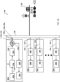
- FIG. 1 is a schematic diagram that shows an example of a system 100 for downhole monitoring using few-mode optical fiber based vibration sensor.
- the system 100 is a phase-sensitive optical time domain reflectometry ( ⁇ -OTDR) based optical fiber distributed acoustic sensor (DAS) system that includes a computing system 110, a sensor system 120, and a fiber under test (FUT) 130.
- the computing system 110 is in electronic communication with the sensor system 120 (such as through a network connection or a universal serial bus connection).
- the FUT 130 is an optical fiber that is optically coupled to the sensor system 120 at a proximal end 122 and extends a distance (multiple kilometers, for example) to a distal end 124.
- the FUT 130 can be extended in oil/gas well 140.
- a vibration source 150 emits vibrations 152 at a particular frequency.
- the vibrations 152 intersect the FUT 130 and vibrate the FUT 130 at, near, or around a location 160.
- the system 100 uses a technique that improves the sensitivity, resolution, or both, of a phase-sensitive optical time domain reflectometry ( ⁇ -OTDR) based optical fiber distributed acoustic sensor (DAS) system.
- ⁇ -OTDR phase-sensitive optical time domain reflectometry
- DAS optical fiber distributed acoustic sensor
- multiple modes of the FUT 130 can be used, and intermodal distortion within the Rayleigh signals that are backscattered on the modes can be reduced or removed to improve system performance for sensing the location, frequency, and amplitude of vibration(s) along the FUT 130.
- FIG. 2A is a block diagram that shows an example of a system 200 for remotely sensing vibration.
- the system 200 can be the example system 100 of FIG. 1 .
- the system 200 includes a light pulse assembly 201a.
- a light source 210a of the light pulse assembly 201a emits light into a single mode fiber (SMF) 212a.
- the light source 210a is a narrow-linewidth (1 kiloHertz (kHz), for example) laser source that generates continuous-wave (CW) light.
- the laser light is modulated by a modulator 214a to produce optical pulses.
- the modulated light is amplified by an optical amplifier 216a.
- the amplified modulated light is provided to an optical port 222a of an optical circulator 220a.
- the optical circulator 220a provides the amplified modulated light to an optical port 224a that is optically coupled to a proximal end 232a of a single mode fiber 230a.
- the optical amplifier 216a may be omitted.
- a distal end 234a of the single mode fiber 230a is optically coupled to an optical port 242a of a mode multiplexer (MUX) 240.
- the mode multiplexer 240 is an optical coupler that allows several standard single mode optical fiber inputs to be selectively converted into the individual modes of a few mode fiber (FMF) 250.
- FMF few mode fiber
- mode multiplexer 240 is configured to couple the optical port 242a to mode 1 (mode one, mode A) of the few mode fiber 250.
- mode 1 mode one, mode A
- other ports of the mode multiplexer 240 can be used, such that light pulses can be launched into any appropriate mode of the few mode fiber 250, an example of which will be discussed in the description of FIG. 2B .
- the term "multiplexer” can also include bidirectional mode multiplexer/demultiplexers (MUX/DEMUX).
- the mode multiplexer 240 is also a mode demultiplexer that allows individual modes of a few mode fiber at an optical fiber input to be selectively converted into the individual single mode optical fibers.
- a device that is configured to perform only mode multiplexing may be used in substantially parallel with a device that is configured to perform only mode demultiplexing (for example, mode multiplexing and demultiplexing can occur at the same time in two separate devices, or the two processes can be performed at different times such as the amount of time it would take for a multiplexed pulse to be injected and then backscattered to the demultiplexer).
- the few mode fiber 250 is several kilometers (km) long (such as 4 km), but this is just one example. In various implementations, any appropriate length of fiber can be used. In some implementations, the few mode fiber 250 can be strung along a region to be monitored and vibrations from sources can be monitored along a region near the few mode fiber 250. For example, the few mode fiber 250 could be extended in buildings, oil/gas wells, or industrial sites to sense vibrations, which might be produced by structural cracks, oil/gas flows, or human/machines activities.
- the backscattered Rayleigh signal is directed by the few mode fiber 250 to the mode multiplexer 240.
- the mode multiplexer 240 directs the backscattered signal to the optical port 242a or another one of a collection of optical ports 242b-242n.
- the optical pulses were directed to mode 1 (one) of the few mode fiber 250, then most of the backscattered Rayleigh signals will be returned though mode 1, and as such, the backscattered signals will be demultiplexed to the optical port 242a and the single mode fiber 230a.
- the remaining backscattered Rayleigh signals guided by other modes of the few mode fiber 250 will be directed to other ports of the mode multiplexer 240.
- Signals backscattered on mode 2 are demultiplexed to the optical port 242b and guided to a light pulse assembly 201b by a single mode fiber 230b.
- Signals backscattered on mode 3 are demultiplexed to the optical port 242c and guided to a light pulse assembly 201c by a single mode fiber 230c.
- Signals backscattered on mode N are demultiplexed to the optical port 242n and guided to a light pulse assembly 201n by a single mode fiber 230n.
- the Rayleigh signals are directed by the optical circulator 220a to an optical port 226a that is optically coupled to a receiver 280a for amplification, detection, and data acquisition.
- a signal processor 282a (such as a computer, an oscilloscope) processes the acquired Rayleigh data and provides information that describes the distribution of vibration locations, amplitudes, and frequencies along the few mode fiber 250.
- the Rayleigh signals are directed by the mode multiplexer 240 a receiver 280b for amplification, detection, and data acquisition.
- a signal processor 282b (such as a computer, an oscilloscope) processes the acquired Rayleigh data and provides information that describes the distribution of vibration locations, amplitudes, and frequencies along the few mode fiber 250.
- the Rayleigh signals are directed by the mode multiplexer 240 a receiver 280c for amplification, detection, and data acquisition.
- a signal processor 282c processes the acquired Rayleigh data and provides information that describes the distribution of vibration locations, amplitudes, and frequencies along the few mode fiber 250.
- the Rayleigh signals are directed by the mode multiplexer 240 a receiver 280n for amplification, detection, and data acquisition.
- a signal processor 282n processes the acquired Rayleigh data and provides information that describes the distribution of vibration locations, amplitudes, and frequencies along the few mode fiber 250.
- the signal processors 282a-282n are configured to remove or reduce the effects of intermodal distortion upon the backscattered Rayleigh signals.
- the distortive properties of the few mode fiber 250 can be identified and reversed in order to recover distortion-reduced versions of the Rayleigh signals.
- the receivers 280a-208n can include an optical amplifier.
- the Rayleigh traces can be amplified by the erbium-doped fiber amplifier, and the amplified spontaneous emission (ASE) noise of the amplified traces can be filtered out by a fiber Bragg grating.
- a photodetector can configured to convert light intensities into electrical signals.
- the filtered backscattered traces can be sensed by the photodetector, and the photodetector can provide representative electrical signals to an analog-to-digital (A/D) converter.
- the analog-to-digital converter can be configured to sample the electrical signals from the photodetector and provide representative digital data to the signal processors 282a-282n for further processing, presentation (for example, to a user), or both.
- FIG. 2B is a block diagram that shows an example of the system 200 in a configuration that transmits light pulses and receives most of the backscattered Rayleigh signals using mode 1 of the few mode fiber 250.
- the system 200 includes the light pulse assembly 201b.
- the light pulse assembly 201b has a configuration and use that is similar to the light pulse assembly 201a.
- a light source 210b of the light pulse assembly 201b emits continuous-wave (CW) light into a single mode fiber (SMF) 212b.
- the laser light is modulated by a modulator 214b to produce optical pulses.
- CW continuous-wave
- SMF single mode fiber
- the modulated light is amplified by an optical amplifier 216b.
- the amplified modulated light is provided to an optical port 222b of an optical circulator 220b.
- the optical circulator 220b provides the amplified modulated light to an optical port 224b that is optically coupled to a proximal end 232b of a single mode fiber 230b.
- the optical amplifier 216b may be omitted.
- a distal end 234b of the single mode fiber 230b is optically coupled to the optical port 242b of a mode multiplexer (MUX) 240.
- mode multiplexer 240 is configured to couple the optical port 242b to mode 1 (one) of the few mode fiber 250.
- the backscattered Rayleigh signal is directed by the few mode fiber 250 to the mode multiplexer 240.
- the optical pulses were directed to mode 2 (two) of the few mode fiber 250, then most of the backscattered Rayleigh signals will be returned though mode 2, and as such the backscattered signals will be demultiplexed to the optical port 242b and the single mode fiber 230b.
- the Rayleigh signals are directed by the optical circulator 220b to an optical port 226b that is optically coupled to a receiver 280b for amplification, detection, and data acquisition.
- a signal processor 282b (such as a computer, an oscilloscope) processes the acquired Rayleigh data and provides information that describes the distribution of vibration locations, amplitudes, and frequencies along the few mode fiber 250.
- the Rayleigh signals are directed by the mode multiplexer 240 the receiver 280a for amplification, detection, and data acquisition.
- the signal processor 282a processes the acquired Rayleigh data and provides information that describes the distribution of vibration locations, amplitudes, and frequencies along the few mode fiber 250.
- the Rayleigh signals are directed by the mode multiplexer 240 the receiver 280c for amplification, detection, and data acquisition.
- the signal processor 282c processes the acquired Rayleigh data and provides information that describes the distribution of vibration locations, amplitudes, and frequencies along the few mode fiber 250.
- the Rayleigh signals are directed by the mode multiplexer 240 the receiver 280n for amplification, detection, and data acquisition.
- the signal processor 282n processes the acquired Rayleigh data and provides information that describes the distribution of vibration locations, amplitudes, and frequencies along the few mode fiber 250.
- the system 200 can experience various amounts of intermodal distortion of light pulses and backscattered Rayleigh signals. This distortion can be caused by intermodal coupling among various modes of the few mode fiber 250.
- intermodal coupling can be negligible. This can be achieved through proper design of the few mode fiber 250. Since the fiber modes are orthogonal to each other, each mode would have its own Rayleigh interference signal apart from the other modes. When detecting the Rayleigh traces of the individual modes, each mode's trace could fully provide the desired vibration information. In such examples, typical signal processing algorithms, such as traces differences and Fourier transform, can be applied for the Rayleigh traces of each mode. In particular, in order to figure out a vibration location along the few mode fiber, the subsequent Rayleigh traces of each mode are subtracted in the time domain. If there are no vibrations, then the subtractions are ideally equal to zero; otherwise, the differences have values that change with time. Once the vibration location is identified, a Fourier transform can be applied at this position on the Rayleigh traces to calculate the frequency components of the vibration.
- typical signal processing algorithms such as traces differences and Fourier transform
- intermodal coupling can be strong, such as when powers rapidly keep transferring among the modes within the few mode fiber 250.
- the recorded modes' signals can become distorted and more advanced signal processing schemes can be implemented in order to extract the vibration information.
- a digital signal processing (DSP) process similar to multiple-input multiple output (MIMO) can be used to reduce or cancel the effect of intermodal coupling.
- MIMO calculates the transfer matrix that describes power transfers among different spatial modes along the few mode fiber. The individual elements of the transfer matrix are calculated via transmitting a training sequence of the modes into the few mode fiber and then measuring them after distortion. By inverting this transfer matrix, the impact of intermodal coupling can be compensated.
- a FMF-based DAS system (such as the example system 100 of FIG. 1 or the example system 200 of FIGs. 2A and 2B ) supports N modes.
- S 1 , S 2 , ..., and S N can represent Rayleigh signals after distortion by Modei, Mode 2 , ... , and Mode N , respectively.
- S 1 S 2 ... S N a 11 a 12 ... a 1 N a 21 a 22 ... a 2 N ... ... ... ... ... a N 1 a N 2 ... a NN S 1 o S 2 o ... S No
- S 1O , S 2O , ..., and S NO are respectively the original (undistorted) Rayleigh signals before distortion of Modei, Mode 2 , ..., and Mode N , respectively.
- the complex coefficients a 11 , a 12 , ..., and a NN represent distortion parameters that quantify the distortion elements produced by intermodal coupling within the few mode fiber.
- a 11 a 12 ... a 1 N a 21 a 22 ... a 2 N ... ... ... ... ... a N 1 a N 2 ... a NN and its inverse: a 11 a 12 ... a 1 N a 21 a 22 ... a 2 N ... ... ... ... ... a N 1 a N 2 ... a NN ⁇ 1 are performed similar to the MIMO approach.
- the individual elements of the transfer matrix are calculated via transmitting a training sequence of the modes into the few mode fiber and then measuring them after distortion. Next, the inverse of the transfer matrix can be mathematically calculated.
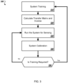
- FIG. 3 is a flow diagram of an example process 300 for determining intermodal distortion parameters.
- the process 300 can be used to determine intermodal distortion parameters of an optical fiber, such as the example fiber under test 130 of FIG. 1 or the example few mode fiber 250 of FIGs. 2A and 2B .
- the intermodal distortion parameters can be used to determine one or more substantially undistorted backscattered Rayleigh signals from one or more distorted backscattered Rayleigh signals (for example, distorted by less than 20%, 10%, 5%, 1%, or 0.1%).
- the process 300 can be used to determine the distortion parameters a 11 , a 12 , ..., and a NN used in Equation 1.
- the system is trained 310 by sending a predetermined S 1O , S 2O , ..., and S NO and measure the corresponding distorted ones S 1 , S 2 , ..., and S N .
- the transfer matrix and its inverse are calculated 320, which includes the elements a 11 , a 12 , ..., and a NN .
- the sensing system is run 330 and the distorted signals S 1 , S 2 , ... , and S N are measured. Under these normal conditions, the S 1O , S 2O , ..., and S NO are calculated using Equation 2.
- the system is calibrated 340 to check whether the transfer matrix elements remain constants or have been changed. If, at 350, the transfer matrix elements are constants, the system continues to be run in normal conditions. Otherwise, the system is trained 310 again. This process is repeated until finishing our measurements.
- FIG. 4 is a flow diagram of an example process 400 for determining intermodal distortion parameters.
- the process 400 can be used to determine intermodal distortion parameters of an optical fiber, such as the example fiber under test 130 of FIG. 1 or the example few mode fiber 250 of FIGs. 2A and 2B .
- the intermodal distortion parameters can be used to determine one or more substantially undistorted backscattered Rayleigh signals from one or more distorted backscattered Rayleigh signals.
- the process 300 can be used to determine the distortion parameters a 11 , a 12 , ..., and a NN used in Equation 1.
- the transfer matrix is initialized.
- An adaptive algorithm is used to measure the transfer matrix, which includes the elements a 11 , a 12 , ..., and a NN . Initial values are assumed for the elements of the transfer matrix.
- Predetermined signals S 1O , S 2O , ..., and S NO are then transmitted 420.
- the corresponding distorted signals S 1 , S 2 , ..., and S N are measured 430.
- the original signals S 1O , S 2O , and S NO are calculated 440.
- an objective function is calculated 450, which is defined as the difference between the predetermined transmitted signals and the calculated ones. If at 460 the objective function is minimized, the sensing system is run at 470. Otherwise, the elements of the transfer matrix are modifed.
- the process 400 ends when finishing the sensing measurements.
- FIG. 5 is a flow diagram of an example process 500 for determining one or more substantially undistorted backscattered Rayleigh signals from one or more distorted backscattered Rayleigh signals.
- the process 500 can be performed by all or parts of the example system 100 of FIG. 1 or the example system 200 of FIGs. 2A and 2B .
- the optical fiber can be a few mode fiber (FMF).
- the system 200 includes the few mode fiber 250.
- the computing system 110 or the signal processors 282a-282n perform the process 500 to reduce or remove intermodal distortion from backscattered Rayleigh signals received from the fiber under test 120 or the few mode fiber 250.
- a collection of distorted backscattered Rayleigh signals are received from a collection of modes of an optical fiber, where the collection of distorted backscattered Rayleigh signals are distorted by an intermodal coupling among the collection of modes.
- the signal processors 282a-282n can receive distorted backscattered Rayleigh signals from the few mode fiber 250, in which the signals are distorted due to intermodal coupling among various modes of the few mode fiber 250.
- a collection of distortion parameters that are descriptive of distortion effects of the intermodal coupling are received.
- the signal processors 282a-282n can receive the distortion parameters a 11 , a 12 , ..., and a NN .
- receiving the collection of distortion parameters that are descriptive of distortion effects of the intermodal coupling can include transmitting a collection of training symbols as a collection of optical pulses through the optical fiber, receiving a collection of training backscattered Rayleigh signals from the collection of modes of the optical fiber, where the collection of training backscattered Rayleigh signals are distorted by the intermodal coupling among the collection of modes, comparing the collection of received training backscattered Rayleigh signals to a collection of predetermined undistorted backscattered Rayleigh signals, determining, based on the comparing, a collection of determined distortion parameters, and providing the collection of determined distortion parameters as the collection of distortion parameters.
- the computing system 100 can perform the example process 300 of FIG. 3 .
- an adaptive algorithm can be used to measure the transfer matrix elements a 11 , a 12 , ... , and a NN ; assuming initial values for the elements of the transfer matrix.
- Predetermined undistorted signals S 1O , S 2O , ..., and S NO can be transmitted, and the corresponding distorted signals S 1 , S 2 , ..., and S N can be received and measured.
- the original signals ( S 1O , S 2O , ..., and S NO ) can be determined using Equation 1, and an objective function can be determined which is defined as the difference between the predetermined transmitted signals and the calculated ones.
- the sensing system can be run, and the objective function can be minimized. Otherwise, the elements of the transfer matrix can be modified, and some or all of the process can be repeated, for example, until the measurement sensing is finished.
- the system can be trained by sending predetermined signals S 1O , S 2O , ..., and S NO and measuring their corresponding distorted signals S 1 , S 2 , ..., and S N ; substituting with the original and distorted signals into Equation 1 and calculating the transfer matrix and its inverse which includes a 11 , a 12 , ... , and a NN ; running the sensing system and measuring only the distorted signals S 1 , S 2 , ..., and S N ; calculating the original signals ( S 1O , S 2O , ..., and S NO ) using Equation 2, calibrating our system to check whether the transfer matrix elements remain constants or have been changed. The system can continue to run in normal conditions, conditioning that the transfer matrix elements are constants. Otherwise, the system can be trained again, repeating the process until the measurement sensing is finished.
- receiving the collection of distortion parameters that are descriptive of distortion effects of the intermodal coupling can include receiving a collection of first distortion parameters, transmitting a collection of optical pulses through the optical fiber, measuring the received collection of distorted backscattered Rayleigh signals, determining, based on the measuring, a collection of second distortion parameters, and providing the collection of second distortion parameters as the collection of distortion parameters that are descriptive of distortion effects of the intermodal coupling.
- the computing system 100 can perform the example process 400 of FIG. 4 .
- an undistorted backscattered Rayleigh signal is determined based on the collection of distorted backscattered Rayleigh signals and the collection of distortion parameters.
- the computing system 100 can determine one or more Rayleigh signals in which the effects of intermodal distortion are reduced or eliminated.
- the process 500 can also include determining at least one transformed Rayleigh signal by removing distortion caused by intermodal coupling from at least one of the distorted backscattered Rayleigh signals, based on the distorted backscattered Rayleigh signals and the collection of distortion parameters, where the collection of distorted backscattered Rayleigh signals are backscattered by a vibration of the optical fiber at a vibration frequency and a vibration amplitude at a vibration location along the optical fiber, determining, based on the transformed Rayleigh signal, at least one of the vibration location, the vibration frequency, and the vibration amplitude, and providing the determined at least one of the vibration location, the vibration frequency, and the vibration amplitude.
- the location, frequency, and amplitude of the vibrations 152 can be determined by the computing system 110.
- the process 500 can include transmitting a collection of optical pulses through a selected mode of an optical fiber, where receiving the collection of distorted backscattered Rayleigh signals from the collection of modes of the optical fiber, where the collection of distorted backscattered Rayleigh signals are distorted by an intermodal coupling among the collection of modes can include separating, by a mode demultiplexer, first backscattered Rayleigh signals from a selected mode of the optical fiber based on a vibration of the optical fiber at a vibration frequency and a vibration amplitude at a vibration location along the optical fiber, and separating, by the mode demultiplexer, second backscattered Rayleigh signals from another selected mode of the optical fiber based on the vibration of the optical fiber.
- the light pulse assembly 201b can inject light pulses on mode 2 of the few mode fiber 250, and receive backscattered Rayleigh signals on one or more of modes 1-n of the few mode fiber 250.
- the process 500 can also include comparing the first backscattered Rayleigh signals and the second backscattered Rayleigh signals, and determining, based on the comparing, an amount of intermodal coupling between the first mode and the second mode.
- the comparing can include detecting differences between the first backscattered Rayleigh signals and the second backscattered Rayleigh signals. In particular, in order to figure out a vibration location along the few mode fiber, subsequent Rayleigh traces of each mode are subtracted in the time domain. If there are no vibrations, the subtractions are ideally equal to zero; otherwise, the differences have values that change with time. Once the vibration location is located, we apply Fourier transform at this position on the Rayleigh traces to calculate the frequency components of the vibration.
- subsequent Rayleigh traces of each mode can be subtracted in the time domain. If there are no vibrations, the subtractions are ideally equal to zero. Otherwise, the differences have values that change with time.
- a Fourier transform can be applied at this position on the Rayleigh traces to calculate the frequency components of the vibration.
- the comparing can include applying a Fourier transform to the first backscattered Rayleigh signals and the second backscattered Rayleigh signals.
- a Fourier transform can be applied at this position on the Rayleigh traces to calculate the frequency components of the vibration.
- the process 500 can also include receiving a collection of distorted backscattered Rayleigh signals from a collection of modes of an optical fiber, where the collection of distorted backscattered Rayleigh signals are distorted by an intermodal coupling among the collection of modes can include receiving a first distorted backscattered Rayleigh signal S 1 from a mode 1 of the optical fiber, receiving a second distorted backscattered Rayleigh signal S 2 from a mode 2 of the optical fiber, ... , and receiving an N th distorted backscattered Rayleigh signal S N from a mode N of the optical fiber, receiving a collection of distortion parameters that are descriptive of distortion effects of the intermodal coupling can also include receiving a distortion parameter a 11 , receiving a distortion parameter a 12 , ...
- determining an undistorted backscattered Rayleigh signal based on the collection of distorted backscattered Rayleigh signals and the collection of distortion parameters can include determining a first undistorted Rayleigh signal S 1o of the first mode, determining a second undistorted Rayleigh signal S 2o of the second mode, ... , and determining a third undistorted Rayleigh signal S No of the third mode, where S 1o , S 2o , ... , and S No are determined based on Equation 1.
- Implementations of the subject matter and the functional operations described in this specification can be implemented in digital electronic circuitry, in tangibly embodied computer software or firmware, in computer hardware, including the structures disclosed in this specification and their structural equivalents, or in combinations of one or more of them.
- Software implementations of the described subject matter can be implemented as one or more computer programs, that is, one or more modules of computer program instructions encoded on a tangible, non-transitory, computer-readable computer-storage medium for execution by, or to control the operation of, data processing apparatus.
- the program instructions can be encoded in/on an artificially generated propagated signal, for example, a machine-generated electrical, optical, or electromagnetic signal that is generated to encode information for transmission to suitable receiver apparatus for execution by a data processing apparatus.
- the computer-storage medium can be a machine-readable storage device, a machine-readable storage substrate, a random or serial access memory device, or a combination of computer-storage mediums.
- data processing apparatus refers to data processing hardware and encompass all kinds of apparatus, devices, and machines for processing data, including by way of example, a programmable processor, a computer, or multiple processors or computers.
- the apparatus can also be, or further include special purpose logic circuitry, for example, a central processing unit (CPU), a field programmable gate array (FPGA), or an application specific integrated circuit (ASIC).
- the data processing apparatus or special purpose logic circuitry may be hardware- or software-based (or a combination of both hardware- and software-based).
- the apparatus can optionally include code that creates an execution environment for computer programs, for example, code that constitutes processor firmware, a protocol stack, a database management system, an operating system, or a combination of execution environments.
- code that constitutes processor firmware for example, code that constitutes processor firmware, a protocol stack, a database management system, an operating system, or a combination of execution environments.
- the present disclosure contemplates the use of data processing apparatuses with or without conventional operating systems, for example, LINUX, UNIX, WINDOWS, MAC OS, ANDROID, IOS, or any other suitable conventional operating system.
- a computer program which may also be referred to or described as a program, software, a software application, a module, a software module, a script, or code can be written in any form of programming language, including compiled or interpreted languages, or declarative or procedural languages, and it can be deployed in any form, including as a stand-alone program or as a module, component, subroutine, or other unit suitable for use in a computing environment.
- a computer program may, but need not, correspond to a file in a file system.
- a program can be stored in a portion of a file that holds other programs or data, for example, one or more scripts stored in a markup language document, in a single file dedicated to the program in question, or in multiple coordinated files, for example, files that store one or more modules, sub programs, or portions of code.
- a computer program can be deployed to be executed on one computer or on multiple computers that are located at one site or distributed across multiple sites and interconnected by a communication network. While portions of the programs illustrated in the various figures are shown as individual modules that implement the various features and functionality through various objects, methods, or other processes, the programs may instead include a number of sub-modules, third-party services, components, libraries, and such, as appropriate. Conversely, the features and functionality of various components can be combined into single components, as appropriate. Thresholds used to make computational determinations can be statically, dynamically, or both statically and dynamically determined.
- the methods, processes, or logic flows described in this specification can be performed by one or more programmable computers executing one or more computer programs to perform functions by operating on input data and generating output.
- the methods, processes, or logic flows can also be performed by, and apparatus can also be implemented as, special purpose logic circuitry, for example, a CPU, an FPGA, or an ASIC.
- Computers suitable for the execution of a computer program can be based on general or special purpose microprocessors, both, or any other kind of CPU.
- a CPU will receive instructions and data from and write to a memory.
- the essential elements of a computer are a CPU, for performing or executing instructions, and one or more memory devices for storing instructions and data.
- a computer will also include, or be operatively coupled to, receive data from or transfer data to, or both, one or more mass storage devices for storing data, for example, magnetic, magneto optical disks, or optical disks.
- mass storage devices for storing data, for example, magnetic, magneto optical disks, or optical disks.
- a computer need not have such devices.
- a computer can be embedded in another device, for example, a mobile telephone, a personal digital assistant (PDA), a mobile audio or video player, a game console, a global positioning system (GPS) receiver, or a portable storage device, for example, a universal serial bus (USB) flash drive, to name just a few.
- PDA personal digital assistant
- GPS global positioning system
- USB universal serial bus
- Computer readable media suitable for storing computer program instructions and data includes all forms of permanent/non-permanent or volatile/nonvolatile memory, media and memory devices, including by way of example semiconductor memory devices, for example, random access memory (RAM), read only memory (ROM), phase change memory (PRAM), static random access memory (SRAM), dynamic random access memory (DRAM), erasable programmable read-only memory (EPROM), electrically erasable programmable read-only memory (EEPROM), and flash memory devices; magnetic devices, for example, tape, cartridges, cassettes, intemal/removable disks; magneto optical disks; and optical memory devices, for example, digital video disc (DVD), CD ROM, DVD+/-R, DVD-RAM, DVD-ROM, HD-DVD, and BLURAY, and other optical memory technologies.
- RAM random access memory
- ROM read only memory
- PRAM phase change memory
- SRAM static random access memory
- DRAM dynamic random access memory
- EPROM erasable programmable read-only
- the memory may store various objects or data, including caches, classes, frameworks, applications, modules, backup data, jobs, web pages, web page templates, data structures, database tables, repositories storing dynamic information, and any other appropriate information including any parameters, variables, algorithms, instructions, rules, constraints, or references to them. Additionally, the memory may include any other appropriate data, such as logs, policies, security or access data, reporting files, as well as others.
- the processor and the memory can be supplemented by, or incorporated in, special purpose logic circuitry.
- implementations of the subject matter described in this specification can be implemented on a computer having a display device, for example, a cathode ray tube (CRT), liquid crystal display (LCD), lightemitting diode (LED), or plasma monitor, for displaying information to the user and a keyboard and a pointing device, for example, a mouse, trackball, or trackpad by which the user can provide input to the computer.
- a display device for example, a cathode ray tube (CRT), liquid crystal display (LCD), lightemitting diode (LED), or plasma monitor
- a keyboard and a pointing device for example, a mouse, trackball, or trackpad by which the user can provide input to the computer.
- Input may also be provided to the computer using a touchscreen, such as a tablet computer surface with pressure sensitivity, a multitouch screen using capacitive or electric sensing, or other type of touchscreen.
- a computer can interact with a user by sending documents to and receiving documents from a device that is used by the user; for example, by sending web pages to a web browser on a user's client device in response to requests received from the web browser.
- GUI graphical user interface
- GUI may be used in the singular or the plural to describe one or more graphical user interfaces and each of the displays of a particular graphical user interface. Therefore, a GUI may represent any graphical user interface, including but not limited to, a web browser, a touch screen, or a command line interface (CLI) that processes information and efficiently presents the information results to the user.
- a GUI may include a collection of user interface (UI) elements, some or all associated with a web browser, such as interactive fields, pulldown lists, and buttons. These and other UI elements may be related to or represent the functions of the web browser.
- UI user interface
- Implementations of the subject matter described in this specification can be implemented in a computing system that includes a back end component, for example, as a data server, or that includes a middleware component, for example, an application server, or that includes a front-end component, for example, a client computer having a graphical user interface or a Web browser through which a user can interact with some implementations of the subject matter described in this specification, or any combination of one or more such back end, middleware, or front end components.
- the components of the system can be interconnected by any form or medium of wireline or wireless digital data communication (or a combination of data communication), for example, a communication network.
- Examples of communication networks include a local area network (LAN), a radio access network (RAN), a metropolitan area network (MAN), a wide area network (WAN), Worldwide Interoperability for Microwave Access (WIMAX), a wireless local area network (WLAN) using, for example, 802.11 a/b/g/n or 802.20 (or a combination of 802.11x and 802.20 or other protocols consistent with this disclosure), all or a portion of the Internet, or any other communication system or systems at one or more locations (or a combination of communication networks).
- the network may communicate with, for example, Internet Protocol (IP) packets, Frame Relay frames, Asynchronous Transfer Mode (ATM) cells, voice, video, data, or other suitable information (or a combination of communication types) between network addresses.
- IP Internet Protocol
- ATM Asynchronous Transfer Mode
- the computing system can include clients and servers.
- a client and server are generally remote from each other and typically interact through a communication network.
- the relationship of client and server arises by virtue of computer programs running on the respective computers and having a client-server relationship to each other.
- Cluster file system involved in this context can be any file system type accessible from multiple servers for read and update. Locking or consistency tracking is not necessary in this context since the locking of exchange file system can be done at application layer. Furthermore, Unicode data files are different from non-Unicode data files.
- any claimed implementation is considered to be applicable to at least a computer-implemented method; a non-transitory, computer-readable medium storing computer-readable instructions to perform the computer-implemented method; and a computer system comprising a computer memory interoperably coupled with a hardware processor configured to perform the computer-implemented method or the instructions stored on the non-transitory, computer-readable medium.
Landscapes
- Physics & Mathematics (AREA)
- Life Sciences & Earth Sciences (AREA)
- Engineering & Computer Science (AREA)
- General Physics & Mathematics (AREA)
- Geology (AREA)
- Geophysics (AREA)
- General Life Sciences & Earth Sciences (AREA)
- Remote Sensing (AREA)
- Environmental & Geological Engineering (AREA)
- Acoustics & Sound (AREA)
- Mining & Mineral Resources (AREA)
- Fluid Mechanics (AREA)
- Geochemistry & Mineralogy (AREA)
- Electromagnetism (AREA)
- Computer Networks & Wireless Communication (AREA)
- Signal Processing (AREA)
- Optical Transform (AREA)
- Measurement Of Mechanical Vibrations Or Ultrasonic Waves (AREA)
- Light Guides In General And Applications Therefor (AREA)
Claims (13)
- Verfahren (500) zum Entfernen von intermodaler Verzerrung, verursacht durch intermodale Kopplung zwischen einer Vielzahl von Moden einer optischen Faser (160, 250), das Verfahren umfassend:Empfangen (510) einer Vielzahl von verzerrten rückgestreuten Rayleigh-Signalen von der Vielzahl von Moden der optischen Faser, wobei die Vielzahl von verzerrten rückgestreuten Rayleigh-Signalen durch eine intermodale Kopplung zwischen der Vielzahl von Moden verzerrt ist; dadurch gekennzeichnet, dass das Verfahren umfasstEmpfangen (520) einer Zusammenstellung von Verzerrungsparametern, die Verzerrungswirkungen der intermodalen Kopplung beschreiben; undBestimmen (530) eines unverzerrten rückgestreuten Rayleigh-Signals basierend auf der Vielzahl von verzerrten rückgestreuten Rayleigh-Signalen und der Zusammenstellung von Verzerrungsparametem.
- Verfahren nach Anspruch 1, ferner umfassend:wobei das Bestimmen (530) eines unverzerrten rückgestreuten Rayleigh-Signal umfasst, ein erstes unverzerrtes Rayleigh-Signal durch Entfernen von Verzerrung, verursacht durch intermodale Kopplung von einem ersten der verzerrten rückgestreuten Rayleigh-Signale, basierend auf den verzerrten rückgestreuten Rayleigh-Signalen und der Zusammenstellung von Verzerrungsparametern, zu bestimmen, wobei das erste der verzerrten rückgestreuten Rayleigh-Signale durch eine Vibration (152) der optischen Faser bei einer Vibrationsfrequenz und einer Vibrationsamplitude an einem Vibrationsort entlang der optischen Faser rückgestreut wird;Bestimmen, basierend auf dem ersten unverzerrten Rayleigh-Signal, mindestens eines des Vibrationsorts, der Vibrationsfrequenz und der Vibrationsamplitude; undBereitstellen des bestimmten mindestens eines des Vibrationsorts, der Vibrationsfrequenz und der Vibrationsamplitude.
- Verfahren nach Anspruch 1, wobei Empfangen einer Zusammenstellung von Verzerrungsparametern, die Verzerrungswirkungen der intermodalen Kopplung beschreiben, umfasst:Übertragen einer Vielzahl von Trainingssymbolen als eine Vielzahl von optischen Impulsen durch die optische Faser;Empfangen einer Vielzahl von rückgestreuten Training-Rayleigh-Signalen von der Vielzahl von Moden der optischen Faser, wobei die Vielzahl von rückgestreuten Training-Rayleigh-Signalen durch die intermodale Kopplung zwischen der Vielzahl von Moden verzerrt ist;Vergleichen der Vielzahl von empfangenen rückgestreuten Training-Rayleigh-Signale mit einer Vielzahl von im Voraus bestimmten unverzerrten rückgestreuten Rayleigh-Signalen;Bestimmen, basierend auf dem Vergleichen, einer Zusammenstellung von bestimmten Verzerrungsparametern; undBereitstellen der Zusammenstellung von bestimmten Verzerrungsparametem als die Zusammenstellung von Verzerrungsparametem.
- Verfahren nach Anspruch 1, wobei Empfangen einer Zusammenstellung von Verzerrungsparametern, die Verzerrungswirkungen der intermodalen Kopplung beschreiben, umfasst:Empfangen einer Zusammenstellung von ersten Verzerrungsparametern;Übertragen einer Vielzahl von optischen Impulsen durch die optische Faser;Messen der empfangenen Vielzahl von verzerrten rückgestreuten Rayleigh-Signalen;Bestimmen, basierend auf dem Messen, einer Zusammenstellung von zweiten Verzerrungsparametern; undBereitstellen der Zusammenstellung von zweiten Verzerrungsparametern als die Zusammenstellung von Verzerrungsparametern, die Verzerrungswirkungen der intermodalen Kopplung beschreiben.
- Verfahren nach Anspruch 1, ferner umfassend:Übertragen einer Vielzahl von optischen Impulsen durch eine ausgewählte Mode einer optischen Faser;wobei Empfangen einer Vielzahl von verzerrten rückgestreuten Rayleigh-Signalen von einer Vielzahl von Moden einer optischen Faser, wobei die Vielzahl von verzerrten rückgestreuten Rayleigh-Signalen durch eine intermodale Kopplung zwischen der Vielzahl von Moden verzerrt ist, umfasst:Trennen, durch einen Moden-Demultiplexer, von ersten rückgestreuten Rayleigh-Signalen von einer ausgewählten Mode A der optischen Faser basierend auf einer Vibration der optischen Faser bei einer Vibrationsfrequenz und einer Vibrationsamplitude an einem Vibrationsort entlang der optischen Faser; undTrennen, durch den Moden-Demultiplexer, von zweiten rückgestreuten Rayleigh-Signalen von einer ausgewählten Mode B der optischen Faser basierend auf der Vibration der optischen Faser.
- Verfahren nach Anspruch 5, ferner umfassend:Vergleichen der ersten rückgestreuten Rayleigh-Signale und der zweiten rückgestreuten Rayleigh-Signale; undBestimmen, basierend auf dem Vergleichen, eines Betrags von intermodaler Kopplung zwischen der Mode A und der Mode B.
- Verfahren nach Anspruch 5, ferner umfassend Detektieren von Differenzen zwischen den ersten rückgestreuten Rayleigh-Signalen und den zweiten rückgestreuten Rayleigh-Signalen.
- Verfahren nach Anspruch 5, ferner umfassend Anwenden einer FourierTransformation auf die ersten rückgestreuten Rayleigh-Signale und die zweiten rückgestreuten Rayleigh-Signale.
- Verfahren nach Anspruch 1, wobei:Empfangen einer Vielzahl von verzerrten rückgestreuten Rayleigh-Signalen von einer Vielzahl von Moden einer optischen Faser, wobei die Vielzahl von verzerrten rückgestreuten Rayleigh-Signalen durch eine intermodale Kopplung zwischen der Vielzahl von Moden verzerrt ist, umfasst:Empfangen eines ersten verzerrten rückgestreuten Rayleigh-Signals S1 von einer Mode 1 der optischen Faser;Empfangen eines zweiten verzerrten rückgestreuten Rayleigh-Signals S2 von einer Mode 2 der optischen Faser; undEmpfangen eines dritten verzerrten rückgestreuten Rayleigh-Signals SN von einer Mode N der optischen Faser;wobei Empfangen einer Zusammenstellung von Verzerrungsparametern, die Verzerrungswirkungen der intermodalen Kopplung beschreiben, ferner umfasst:Empfangen eines Verzerrungsparameters a11 ;Empfangen eines Verzerrungsparameters a12 ; undEmpfangen eines Verzerrungsparameters aNN ;wobei Bestimmen eines unverzerrten rückgestreuten Rayleigh-Signals basierend auf der Vielzahl von verzerrten rückgestreuten Rayleigh-Signalen und der Zusammenstellung von Verzerrungsparametem umfasst:Bestimmen eines ersten unverzerrten Rayleigh-Signals S10 der Mode 1;Bestimmen eines zweiten unverzerrten Rayleigh-Signals S20 der Mode 2; undBestimmen eines dritten unverzerrten Rayleigh-Signals SN0 der Mode N;wobei S10, S20 und SN0 bestimmt sind als:

- Verfahren nach Anspruch 1, wobei die optische Faser eine Faser mit wenigen Moden, FMF, ist.
- Nichttransitorisches Computerspeichermedium, codiert mit einem Computerprogramm, das Computerprogramm umfassend Anweisungen, die, wenn sie durch ein Datenverarbeitungsgerät ausgeführt werden, ein Datenverarbeitungsgerät veranlassen, das Verfahren nach einem der Ansprüche 1, 2, 9 und 10 durchzuführen.
- Vibrationssensorsystem, umfassend:einen Lichtimpulsgenerator, konfiguriert zum Bereitstellen einer Vielzahl von optischen Impulsen;eine optische Faser mit wenigen Moden (160, 250), die eine im Voraus bestimmte Länge aufweist und konfiguriert ist zum Leiten der optischen Impulse;einen Sensor (280), konfiguriert zum Bestimmen eines Orts und einer Frequenz einer Vibration der optischen Faser an einem Ort entlang der optischen Faser, basierend auf einer Zusammenstellung von Verzerrungsparametern, die eine Verzerrung von rückgestreuten Rayleigh-Signalen, verursacht durch intermodale Kopplung in der optischen Faser mit wenigen Moden, repräsentieren; undein nichttransitorisches Computerspeichermedium, codiert nach Anspruch 11.
- Vibrationssensorsystem nach Anspruch 12, wobei der Lichtimpulsgenerator umfasst:eine Lichtquelle (210), konfiguriert zum Erzeugen von kontinuierlichem Licht;einen ersten optischen Modulator (214), konfiguriert zum Umwandeln des kontinuierlichen Lichts in die Vielzahl von optischen Impulsen, die eine im Voraus bestimmte Frequenz aufweisen;einen optischen Verstärker (216), konfiguriert zum Verstärken der Vielzahl von optischen Impulsen; undeinen optischen Zirkulator (220) mit einem ersten Anschluss, konfiguriert zum Empfangen der optischen Impulse und Bereitstellen der optischen Impulse einem zweiten Anschluss, der an die optische Faser optisch gekoppelt ist, wobei der zweite Anschluss außerdem konfiguriert ist zum Empfangen von rückgestreuten Rayleigh-Signalen und Bereitstellen der rückgestreuten Rayleigh-Signale einem dritten Anschluss, der mit dem Sensor in optischer Kommunikation ist.
Applications Claiming Priority (2)
| Application Number | Priority Date | Filing Date | Title |
|---|---|---|---|
| US16/299,918 US12019200B2 (en) | 2019-03-12 | 2019-03-12 | Downhole monitoring using few-mode optical fiber based distributed acoustic sensing |
| PCT/US2020/021717 WO2020185682A1 (en) | 2019-03-12 | 2020-03-09 | Downhole monitoring using few-mode optical fiber based distributed acoustic sensing |
Publications (2)
| Publication Number | Publication Date |
|---|---|
| EP3938744A1 EP3938744A1 (de) | 2022-01-19 |
| EP3938744B1 true EP3938744B1 (de) | 2023-08-30 |
Family
ID=70166165
Family Applications (1)
| Application Number | Title | Priority Date | Filing Date |
|---|---|---|---|
| EP20717030.9A Active EP3938744B1 (de) | 2019-03-12 | 2020-03-09 | Bohrlochüberwachung unter verwendung von optischer faser mit optischer faser und verteilter akustischer abtastung |
Country Status (6)
| Country | Link |
|---|---|
| US (2) | US12019200B2 (de) |
| EP (1) | EP3938744B1 (de) |
| CN (1) | CN113939718B (de) |
| CA (1) | CA3133228A1 (de) |
| SA (1) | SA521430270B1 (de) |
| WO (1) | WO2020185682A1 (de) |
Families Citing this family (7)
| Publication number | Priority date | Publication date | Assignee | Title |
|---|---|---|---|---|
| US12019200B2 (en) * | 2019-03-12 | 2024-06-25 | Saudi Arabian Oil Company | Downhole monitoring using few-mode optical fiber based distributed acoustic sensing |
| WO2020240724A1 (ja) * | 2019-05-29 | 2020-12-03 | 日本電気株式会社 | 光ファイバセンシングシステム、光ファイバセンシング機器及び音出力方法 |
| WO2022101958A1 (ja) * | 2020-11-10 | 2022-05-19 | 日本電信電話株式会社 | 空間多重光伝送路の特性を評価する装置及び方法 |
| CN112461353B (zh) * | 2020-12-15 | 2022-07-12 | 成都陆迪盛华科技有限公司 | 一种在光放大下分布式光纤振动传感的编码装置及方法 |
| CN115200691B (zh) * | 2021-04-09 | 2025-04-15 | 中国科学院上海光学精密机械研究所 | 一种少模光纤分布式声传感系统及其信号处理方法 |
| US12287234B2 (en) * | 2021-10-15 | 2025-04-29 | Nec Corporation | Distributed acoustic sensing sensitivity enhancement using MIMO sampling and phase recombination |
| CN120236606B (zh) * | 2025-05-30 | 2025-08-19 | 高勘(广州)技术有限公司 | 基于das的音频数据获取方法、系统、电子设备及存储介质 |
Citations (1)
| Publication number | Priority date | Publication date | Assignee | Title |
|---|---|---|---|---|
| US9100085B2 (en) * | 2011-09-21 | 2015-08-04 | Spatial Digital Systems, Inc. | High speed multi-mode fiber transmissions via orthogonal wavefronts |
Family Cites Families (55)
| Publication number | Priority date | Publication date | Assignee | Title |
|---|---|---|---|---|
| JPS5983018A (ja) * | 1982-11-04 | 1984-05-14 | Furukawa Electric Co Ltd:The | 光フアイバ振動測定方法 |
| US5224182A (en) | 1991-08-29 | 1993-06-29 | Virginia Polytechnic Institute And State University | Spatially-weighted two-mode optical fiber sensors |
| US5659568A (en) * | 1995-05-23 | 1997-08-19 | Hewlett-Packard Company | Low noise surface emitting laser for multimode optical link applications |
| US5892860A (en) | 1997-01-21 | 1999-04-06 | Cidra Corporation | Multi-parameter fiber optic sensor for use in harsh environments |
| WO1998050680A2 (en) | 1997-05-02 | 1998-11-12 | Baker Hughes Incorporated | Monitoring of downhole parameters and tools utilizing fiber optics |
| GB9710057D0 (en) | 1997-05-19 | 1997-07-09 | King S College London | Distributed sensing system |
| US6193079B1 (en) | 1999-04-29 | 2001-02-27 | Dci Marketing, Inc. | Product display and support |
| US6728165B1 (en) | 1999-10-29 | 2004-04-27 | Litton Systems, Inc. | Acoustic sensing system for downhole seismic applications utilizing an array of fiber optic sensors |
| US6718087B2 (en) * | 2000-03-22 | 2004-04-06 | University Of Maryland Baltimore County | System and method for reducing differential mode dispersion effects in multimode optical fiber transmissions |
| US20050047779A1 (en) * | 2003-09-02 | 2005-03-03 | Harris Corporation | Post-detection, fiber optic dispersion compensation using adjustable inverse distortion operator employing trained or decision-based parameter adaptation (estimation) |
| US8072595B1 (en) * | 2005-08-29 | 2011-12-06 | Optech Ventures, Llc | Time correlation system and method |
| JP2007135124A (ja) * | 2005-11-14 | 2007-05-31 | Matsushita Electric Ind Co Ltd | マルチモード光伝送システム |
| EP1969997A1 (de) * | 2007-03-12 | 2008-09-17 | Radiometer Basel AG | Sensorensystem |
| JP4441624B2 (ja) * | 2007-08-07 | 2010-03-31 | 日本電信電話株式会社 | 光ファイバを用いた歪・温度の分布測定方法及び測定装置 |
| US7668411B2 (en) | 2008-06-06 | 2010-02-23 | Schlumberger Technology Corporation | Distributed vibration sensing system using multimode fiber |
| CN101592475B (zh) | 2009-06-08 | 2010-09-29 | 中国计量学院 | 全分布式光纤瑞利与拉曼散射光子应变、温度传感器 |
| US20110088462A1 (en) | 2009-10-21 | 2011-04-21 | Halliburton Energy Services, Inc. | Downhole monitoring with distributed acoustic/vibration, strain and/or density sensing |
| CN101839759B (zh) * | 2010-04-22 | 2011-09-07 | 合肥奥镭光电科技有限责任公司 | 一种少模光纤倾斜光栅振动传感系统 |
| US8493555B2 (en) | 2011-04-29 | 2013-07-23 | Corning Incorporated | Distributed Brillouin sensing systems and methods using few-mode sensing optical fiber |
| US8948550B2 (en) | 2012-02-21 | 2015-02-03 | Corning Incorporated | Sensing systems and few-mode optical fiber for use in such systems |
| CN102564642B (zh) | 2012-02-21 | 2013-08-07 | 中国计量学院 | 融合拉曼放大效应的光纤拉曼频移器的全分布光纤传感器 |
| DE102013200033B4 (de) * | 2012-10-10 | 2023-06-15 | Rohde & Schwarz GmbH & Co. Kommanditgesellschaft | Verfahren und System zur Bestimmung von Streuparametern eines frequenzumsetzenden Messobjekts |
| US9197356B2 (en) | 2012-11-16 | 2015-11-24 | At&T Intellectual Property I, L.P. | Distributed spatial mode processing for spatial-mode multiplexed communication systems |
| BR112015014522A2 (pt) | 2012-12-19 | 2017-07-11 | Toray Industries | método para produzir um álcool |
| US9581489B2 (en) | 2013-01-26 | 2017-02-28 | Halliburton Energy Services, Inc. | Distributed acoustic sensing with multimode fiber |
| US9148667B2 (en) * | 2013-02-06 | 2015-09-29 | Qualcomm Incorporated | Intra prediction mode decision with reduced storage |
| US8947659B1 (en) * | 2013-02-26 | 2015-02-03 | Optech Ventures, Llc | Time correlated single photon counting by time to digital conversion |
| US9319139B2 (en) * | 2013-03-11 | 2016-04-19 | Futurewei Technologies, Inc. | Long distance multi-mode communication |
| US9617847B2 (en) | 2013-10-29 | 2017-04-11 | Halliburton Energy Services, Inc. | Robust optical fiber-based distributed sensing systems and methods |
| US9429466B2 (en) | 2013-10-31 | 2016-08-30 | Halliburton Energy Services, Inc. | Distributed acoustic sensing systems and methods employing under-filled multi-mode optical fiber |
| CN103616089B (zh) | 2013-12-04 | 2017-10-13 | 威海北洋电气集团股份有限公司 | 一种光纤温度振动传感器及综合监控系统和方法 |
| CN103913186A (zh) | 2014-04-25 | 2014-07-09 | 重庆大学 | 基于瑞利散射和拉曼散射的多参数分布式光纤传感系统 |
| US10378971B2 (en) * | 2014-07-25 | 2019-08-13 | Université de Mons | Temperature sensor |
| CN104198030B (zh) * | 2014-08-29 | 2017-11-10 | 中国石油天然气股份有限公司 | 基于相干瑞利散射的多路振动检测方法及其检测系统 |
| US9599460B2 (en) | 2014-10-16 | 2017-03-21 | Nec Corporation | Hybrid Raman and Brillouin scattering in few-mode fibers |
| EP3237874B1 (de) * | 2014-12-23 | 2023-01-25 | ENI S.p.A. | System zur reflektometrischen vibrationsmessung und zugehöriges verfahren zur überwachung von mehrphasenströmungen |
| US10113935B2 (en) | 2015-01-08 | 2018-10-30 | Nec Corporation | Distributed multi-channel coherent optical fiber sensing system |
| US10018523B2 (en) | 2015-01-08 | 2018-07-10 | Nec Corporation | Multi-parameter sensing based on few-mode fiber Bragg gratings using femtosecond IR laser |
| CN105043586B (zh) | 2015-05-28 | 2018-01-09 | 华中科技大学 | 一种基于少模光纤的拉曼分布式测温系统和测温方法 |
| CN105136337A (zh) | 2015-05-28 | 2015-12-09 | 华中科技大学 | 一种基于模式复用的拉曼分布式测温系统和测温方法 |
| CN105021307A (zh) | 2015-07-11 | 2015-11-04 | 苏州至禅光纤传感技术有限公司 | 一种实现全光纤分布式多参量传感的方法 |
| US10536238B2 (en) * | 2016-01-12 | 2020-01-14 | Nippon Telegraph And Telephone Corporation | Optical transmission system, optical transmission apparatus, and optical reception apparatus |
| GB201601060D0 (en) | 2016-01-20 | 2016-03-02 | Fotech Solutions Ltd | Distributed optical fibre sensors |
| US20170353241A1 (en) * | 2016-06-02 | 2017-12-07 | Irfan Muhammad Fazal | Image-Processing System to Improve Modal Purity and Reduce Modal Crosstalk |
| US10018558B2 (en) | 2016-08-22 | 2018-07-10 | Nec Corporation | Distributed acoustic sensing in a multicore optical fiber using distributed mode coupling, delay, and simultaneous pulsing with selectable spatial modes |
| JP6885023B2 (ja) | 2016-11-16 | 2021-06-09 | セイコーエプソン株式会社 | 画像処理装置および画像処理方法 |
| CN106895959B (zh) | 2017-04-17 | 2019-01-25 | 吉林大学 | 一种基于双光子灯笼和少模光纤环形器的少模光纤模式耦合测量装置 |
| CN107238415A (zh) | 2017-07-27 | 2017-10-10 | 中国地质大学(武汉) | 用于检测全分布式光纤的温度及振动位置的传感器 |
| CN107664541A (zh) | 2017-09-18 | 2018-02-06 | 南京大学 | 一种分布式光纤振动和温度融合传感系统及方法 |
| US11965831B2 (en) * | 2018-03-01 | 2024-04-23 | The Regents Of The University Of Colorado, A Body Corporate | Methods and systems for stimulated emission depletion microscopy |
| CN207923277U (zh) | 2018-03-12 | 2018-09-28 | 广东电网有限责任公司东莞供电局 | 基于模式复用的单偏振态光纤振动传感系统 |
| CN108534910A (zh) | 2018-03-19 | 2018-09-14 | 浙江师范大学 | 一种基于非对称双芯光纤的分布式双参量传感方法 |
| US10634553B1 (en) | 2019-01-30 | 2020-04-28 | Saudi Arabian Oil Company | Hybrid distributed acoustic testing |
| US10962408B2 (en) * | 2019-03-07 | 2021-03-30 | Saudi Arabian Oil Company | Quasi-fundamental-mode operated multimode fiber for distributed acoustic sensing |
| US12019200B2 (en) * | 2019-03-12 | 2024-06-25 | Saudi Arabian Oil Company | Downhole monitoring using few-mode optical fiber based distributed acoustic sensing |
-
2019
- 2019-03-12 US US16/299,918 patent/US12019200B2/en active Active
-
2020
- 2020-03-09 WO PCT/US2020/021717 patent/WO2020185682A1/en not_active Ceased
- 2020-03-09 CN CN202080020480.1A patent/CN113939718B/zh active Active
- 2020-03-09 EP EP20717030.9A patent/EP3938744B1/de active Active
- 2020-03-09 CA CA3133228A patent/CA3133228A1/en active Pending
-
2021
- 2021-09-09 SA SA521430270A patent/SA521430270B1/ar unknown
-
2024
- 2024-05-13 US US18/662,537 patent/US12481081B2/en active Active
Patent Citations (1)
| Publication number | Priority date | Publication date | Assignee | Title |
|---|---|---|---|---|
| US9100085B2 (en) * | 2011-09-21 | 2015-08-04 | Spatial Digital Systems, Inc. | High speed multi-mode fiber transmissions via orthogonal wavefronts |
Also Published As
| Publication number | Publication date |
|---|---|
| CN113939718B (zh) | 2024-11-05 |
| CN113939718A (zh) | 2022-01-14 |
| SA521430270B1 (ar) | 2024-07-30 |
| EP3938744A1 (de) | 2022-01-19 |
| US20200292727A1 (en) | 2020-09-17 |
| US12019200B2 (en) | 2024-06-25 |
| CA3133228A1 (en) | 2020-09-17 |
| US12481081B2 (en) | 2025-11-25 |
| US20240295669A1 (en) | 2024-09-05 |
| WO2020185682A1 (en) | 2020-09-17 |
Similar Documents
| Publication | Publication Date | Title |
|---|---|---|
| US12481081B2 (en) | Downhole monitoring using few-mode optical fiber based distributed acoustic sensing | |
| US11209307B2 (en) | Hybrid distributed acoustic testing | |
| US12066308B2 (en) | Distributed optical fibre vibration sensor | |
| EP3111042B1 (de) | Verteilte akustische sensormesslängeneffektminderung | |
| Sha et al. | Phase demodulation method in phase-sensitive OTDR without coherent detection | |
| US10345138B2 (en) | Method to increase the signal to noise ratio of distributed acoustic sensing by spatial averaging | |
| US11698288B2 (en) | Signal to noise ratio management | |
| US20160356917A1 (en) | Chemical sensing using quantum entanglement between photons | |
| US9404831B2 (en) | Arrayed wave division multiplex to extend range of IOFDR fiber bragg sensing system | |
| AU2020386881B2 (en) | Drift correction in a fiber optic distributed acoustic sensing system | |
| Li et al. | A high-performance DAS system using point-backscattering-enhanced fiber and study of its noise characteristics | |
| US10221682B2 (en) | Downhole sensing systems and methods employing squeezed light interferometry | |
| Yucel et al. | The measurement of strain of a prototype pulley system using a Brillouin optical time domain analysis | |
| Liu et al. | Overcoming acoustic crosstalk in the BOTDA sensor with a bidirectional frequency-modulated probe | |
| Luckanachai et al. | Permanent DAS/DTS Monitoring for SAGD Production–Design, Results, and Recommendations | |
| Chen et al. | Accurate single-ended distributed temperature sensing | |
| Turolla et al. | Distributed Acoustic Sensing (DAS) System with Multimode Fibers: Method and O&G Applications | |
| Vandborg | Temperature and Strain Measurements using Brillouin OTDR | |
| Bernini et al. | Centimeter-range spatial resolution distributed sensing by BOFDA | |
| Prasanth et al. | Distributed fiber optic sensor based on correlation coded Brillouin scattering for long range condition monitoring |
Legal Events
| Date | Code | Title | Description |
|---|---|---|---|
| STAA | Information on the status of an ep patent application or granted ep patent |
Free format text: STATUS: UNKNOWN |
|
| STAA | Information on the status of an ep patent application or granted ep patent |
Free format text: STATUS: THE INTERNATIONAL PUBLICATION HAS BEEN MADE |
|
| PUAI | Public reference made under article 153(3) epc to a published international application that has entered the european phase |
Free format text: ORIGINAL CODE: 0009012 |
|
| STAA | Information on the status of an ep patent application or granted ep patent |
Free format text: STATUS: REQUEST FOR EXAMINATION WAS MADE |
|
| 17P | Request for examination filed |
Effective date: 20210917 |
|
| AK | Designated contracting states |
Kind code of ref document: A1 Designated state(s): AL AT BE BG CH CY CZ DE DK EE ES FI FR GB GR HR HU IE IS IT LI LT LU LV MC MK MT NL NO PL PT RO RS SE SI SK SM TR |
|
| DAV | Request for validation of the european patent (deleted) | ||
| DAX | Request for extension of the european patent (deleted) | ||
| GRAP | Despatch of communication of intention to grant a patent |
Free format text: ORIGINAL CODE: EPIDOSNIGR1 |
|
| STAA | Information on the status of an ep patent application or granted ep patent |
Free format text: STATUS: GRANT OF PATENT IS INTENDED |
|
| INTG | Intention to grant announced |
Effective date: 20230323 |
|
| GRAJ | Information related to disapproval of communication of intention to grant by the applicant or resumption of examination proceedings by the epo deleted |
Free format text: ORIGINAL CODE: EPIDOSDIGR1 |
|
| STAA | Information on the status of an ep patent application or granted ep patent |
Free format text: STATUS: REQUEST FOR EXAMINATION WAS MADE |
|
| GRAP | Despatch of communication of intention to grant a patent |
Free format text: ORIGINAL CODE: EPIDOSNIGR1 |
|
| STAA | Information on the status of an ep patent application or granted ep patent |
Free format text: STATUS: GRANT OF PATENT IS INTENDED |
|
| INTC | Intention to grant announced (deleted) | ||
| INTG | Intention to grant announced |
Effective date: 20230609 |
|
| P01 | Opt-out of the competence of the unified patent court (upc) registered |
Effective date: 20230608 |
|
| GRAS | Grant fee paid |
Free format text: ORIGINAL CODE: EPIDOSNIGR3 |
|
| GRAA | (expected) grant |
Free format text: ORIGINAL CODE: 0009210 |
|
| STAA | Information on the status of an ep patent application or granted ep patent |
Free format text: STATUS: THE PATENT HAS BEEN GRANTED |
|
| AK | Designated contracting states |
Kind code of ref document: B1 Designated state(s): AL AT BE BG CH CY CZ DE DK EE ES FI FR GB GR HR HU IE IS IT LI LT LU LV MC MK MT NL NO PL PT RO RS SE SI SK SM TR |
|
| REG | Reference to a national code |
Ref country code: GB Ref legal event code: FG4D |
|
| REG | Reference to a national code |
Ref country code: CH Ref legal event code: EP |
|
| REG | Reference to a national code |
Ref country code: DE Ref legal event code: R096 Ref document number: 602020016694 Country of ref document: DE |
|
| REG | Reference to a national code |
Ref country code: IE Ref legal event code: FG4D |
|
| REG | Reference to a national code |
Ref country code: NO Ref legal event code: T2 Effective date: 20230830 |
|
| REG | Reference to a national code |
Ref country code: LT Ref legal event code: MG9D |
|
| REG | Reference to a national code |
Ref country code: NL Ref legal event code: MP Effective date: 20230830 |
|
| REG | Reference to a national code |
Ref country code: AT Ref legal event code: MK05 Ref document number: 1606006 Country of ref document: AT Kind code of ref document: T Effective date: 20230830 |
|
| PG25 | Lapsed in a contracting state [announced via postgrant information from national office to epo] |
Ref country code: GR Free format text: LAPSE BECAUSE OF FAILURE TO SUBMIT A TRANSLATION OF THE DESCRIPTION OR TO PAY THE FEE WITHIN THE PRESCRIBED TIME-LIMIT Effective date: 20231201 |
|
| PG25 | Lapsed in a contracting state [announced via postgrant information from national office to epo] |
Ref country code: IS Free format text: LAPSE BECAUSE OF FAILURE TO SUBMIT A TRANSLATION OF THE DESCRIPTION OR TO PAY THE FEE WITHIN THE PRESCRIBED TIME-LIMIT Effective date: 20231230 |
|
| PG25 | Lapsed in a contracting state [announced via postgrant information from national office to epo] |
Ref country code: SE Free format text: LAPSE BECAUSE OF FAILURE TO SUBMIT A TRANSLATION OF THE DESCRIPTION OR TO PAY THE FEE WITHIN THE PRESCRIBED TIME-LIMIT Effective date: 20230830 Ref country code: RS Free format text: LAPSE BECAUSE OF FAILURE TO SUBMIT A TRANSLATION OF THE DESCRIPTION OR TO PAY THE FEE WITHIN THE PRESCRIBED TIME-LIMIT Effective date: 20230830 Ref country code: LV Free format text: LAPSE BECAUSE OF FAILURE TO SUBMIT A TRANSLATION OF THE DESCRIPTION OR TO PAY THE FEE WITHIN THE PRESCRIBED TIME-LIMIT Effective date: 20230830 Ref country code: LT Free format text: LAPSE BECAUSE OF FAILURE TO SUBMIT A TRANSLATION OF THE DESCRIPTION OR TO PAY THE FEE WITHIN THE PRESCRIBED TIME-LIMIT Effective date: 20230830 Ref country code: IS Free format text: LAPSE BECAUSE OF FAILURE TO SUBMIT A TRANSLATION OF THE DESCRIPTION OR TO PAY THE FEE WITHIN THE PRESCRIBED TIME-LIMIT Effective date: 20231230 Ref country code: HR Free format text: LAPSE BECAUSE OF FAILURE TO SUBMIT A TRANSLATION OF THE DESCRIPTION OR TO PAY THE FEE WITHIN THE PRESCRIBED TIME-LIMIT Effective date: 20230830 Ref country code: GR Free format text: LAPSE BECAUSE OF FAILURE TO SUBMIT A TRANSLATION OF THE DESCRIPTION OR TO PAY THE FEE WITHIN THE PRESCRIBED TIME-LIMIT Effective date: 20231201 Ref country code: FI Free format text: LAPSE BECAUSE OF FAILURE TO SUBMIT A TRANSLATION OF THE DESCRIPTION OR TO PAY THE FEE WITHIN THE PRESCRIBED TIME-LIMIT Effective date: 20230830 Ref country code: AT Free format text: LAPSE BECAUSE OF FAILURE TO SUBMIT A TRANSLATION OF THE DESCRIPTION OR TO PAY THE FEE WITHIN THE PRESCRIBED TIME-LIMIT Effective date: 20230830 |
|
| PG25 | Lapsed in a contracting state [announced via postgrant information from national office to epo] |
Ref country code: PL Free format text: LAPSE BECAUSE OF FAILURE TO SUBMIT A TRANSLATION OF THE DESCRIPTION OR TO PAY THE FEE WITHIN THE PRESCRIBED TIME-LIMIT Effective date: 20230830 Ref country code: NL Free format text: LAPSE BECAUSE OF FAILURE TO SUBMIT A TRANSLATION OF THE DESCRIPTION OR TO PAY THE FEE WITHIN THE PRESCRIBED TIME-LIMIT Effective date: 20230830 |
|
| PG25 | Lapsed in a contracting state [announced via postgrant information from national office to epo] |
Ref country code: ES Free format text: LAPSE BECAUSE OF FAILURE TO SUBMIT A TRANSLATION OF THE DESCRIPTION OR TO PAY THE FEE WITHIN THE PRESCRIBED TIME-LIMIT Effective date: 20230830 |
|
| PG25 | Lapsed in a contracting state [announced via postgrant information from national office to epo] |
Ref country code: SM Free format text: LAPSE BECAUSE OF FAILURE TO SUBMIT A TRANSLATION OF THE DESCRIPTION OR TO PAY THE FEE WITHIN THE PRESCRIBED TIME-LIMIT Effective date: 20230830 Ref country code: RO Free format text: LAPSE BECAUSE OF FAILURE TO SUBMIT A TRANSLATION OF THE DESCRIPTION OR TO PAY THE FEE WITHIN THE PRESCRIBED TIME-LIMIT Effective date: 20230830 Ref country code: ES Free format text: LAPSE BECAUSE OF FAILURE TO SUBMIT A TRANSLATION OF THE DESCRIPTION OR TO PAY THE FEE WITHIN THE PRESCRIBED TIME-LIMIT Effective date: 20230830 Ref country code: EE Free format text: LAPSE BECAUSE OF FAILURE TO SUBMIT A TRANSLATION OF THE DESCRIPTION OR TO PAY THE FEE WITHIN THE PRESCRIBED TIME-LIMIT Effective date: 20230830 Ref country code: DK Free format text: LAPSE BECAUSE OF FAILURE TO SUBMIT A TRANSLATION OF THE DESCRIPTION OR TO PAY THE FEE WITHIN THE PRESCRIBED TIME-LIMIT Effective date: 20230830 Ref country code: CZ Free format text: LAPSE BECAUSE OF FAILURE TO SUBMIT A TRANSLATION OF THE DESCRIPTION OR TO PAY THE FEE WITHIN THE PRESCRIBED TIME-LIMIT Effective date: 20230830 Ref country code: PT Free format text: LAPSE BECAUSE OF FAILURE TO SUBMIT A TRANSLATION OF THE DESCRIPTION OR TO PAY THE FEE WITHIN THE PRESCRIBED TIME-LIMIT Effective date: 20240102 Ref country code: SK Free format text: LAPSE BECAUSE OF FAILURE TO SUBMIT A TRANSLATION OF THE DESCRIPTION OR TO PAY THE FEE WITHIN THE PRESCRIBED TIME-LIMIT Effective date: 20230830 |
|
| PG25 | Lapsed in a contracting state [announced via postgrant information from national office to epo] |
Ref country code: IT Free format text: LAPSE BECAUSE OF FAILURE TO SUBMIT A TRANSLATION OF THE DESCRIPTION OR TO PAY THE FEE WITHIN THE PRESCRIBED TIME-LIMIT Effective date: 20230830 |
|
| REG | Reference to a national code |
Ref country code: DE Ref legal event code: R097 Ref document number: 602020016694 Country of ref document: DE |
|
| PLBE | No opposition filed within time limit |
Free format text: ORIGINAL CODE: 0009261 |
|
| STAA | Information on the status of an ep patent application or granted ep patent |
Free format text: STATUS: NO OPPOSITION FILED WITHIN TIME LIMIT |
|
| PG25 | Lapsed in a contracting state [announced via postgrant information from national office to epo] |
Ref country code: SI Free format text: LAPSE BECAUSE OF FAILURE TO SUBMIT A TRANSLATION OF THE DESCRIPTION OR TO PAY THE FEE WITHIN THE PRESCRIBED TIME-LIMIT Effective date: 20230830 |
|
| 26N | No opposition filed |
Effective date: 20240603 |
|
| REG | Reference to a national code |
Ref country code: CH Ref legal event code: PL |
|
| PG25 | Lapsed in a contracting state [announced via postgrant information from national office to epo] |
Ref country code: BG Free format text: LAPSE BECAUSE OF FAILURE TO SUBMIT A TRANSLATION OF THE DESCRIPTION OR TO PAY THE FEE WITHIN THE PRESCRIBED TIME-LIMIT Effective date: 20230830 |
|
| PG25 | Lapsed in a contracting state [announced via postgrant information from national office to epo] |
Ref country code: LU Free format text: LAPSE BECAUSE OF NON-PAYMENT OF DUE FEES Effective date: 20240309 |
|
| PG25 | Lapsed in a contracting state [announced via postgrant information from national office to epo] |
Ref country code: MC Free format text: LAPSE BECAUSE OF FAILURE TO SUBMIT A TRANSLATION OF THE DESCRIPTION OR TO PAY THE FEE WITHIN THE PRESCRIBED TIME-LIMIT Effective date: 20230830 |
|
| PG25 | Lapsed in a contracting state [announced via postgrant information from national office to epo] |
Ref country code: MC Free format text: LAPSE BECAUSE OF FAILURE TO SUBMIT A TRANSLATION OF THE DESCRIPTION OR TO PAY THE FEE WITHIN THE PRESCRIBED TIME-LIMIT Effective date: 20230830 Ref country code: LU Free format text: LAPSE BECAUSE OF NON-PAYMENT OF DUE FEES Effective date: 20240309 Ref country code: BG Free format text: LAPSE BECAUSE OF FAILURE TO SUBMIT A TRANSLATION OF THE DESCRIPTION OR TO PAY THE FEE WITHIN THE PRESCRIBED TIME-LIMIT Effective date: 20230830 |
|
| REG | Reference to a national code |
Ref country code: BE Ref legal event code: MM Effective date: 20240331 |
|
| PG25 | Lapsed in a contracting state [announced via postgrant information from national office to epo] |
Ref country code: BE Free format text: LAPSE BECAUSE OF NON-PAYMENT OF DUE FEES Effective date: 20240331 |
|
| PG25 | Lapsed in a contracting state [announced via postgrant information from national office to epo] |
Ref country code: FR Free format text: LAPSE BECAUSE OF NON-PAYMENT OF DUE FEES Effective date: 20240331 |
|
| PG25 | Lapsed in a contracting state [announced via postgrant information from national office to epo] |
Ref country code: IE Free format text: LAPSE BECAUSE OF NON-PAYMENT OF DUE FEES Effective date: 20240309 |
|
| PG25 | Lapsed in a contracting state [announced via postgrant information from national office to epo] |
Ref country code: IE Free format text: LAPSE BECAUSE OF NON-PAYMENT OF DUE FEES Effective date: 20240309 Ref country code: FR Free format text: LAPSE BECAUSE OF NON-PAYMENT OF DUE FEES Effective date: 20240331 Ref country code: BE Free format text: LAPSE BECAUSE OF NON-PAYMENT OF DUE FEES Effective date: 20240331 Ref country code: CH Free format text: LAPSE BECAUSE OF NON-PAYMENT OF DUE FEES Effective date: 20240331 |
|
| PGFP | Annual fee paid to national office [announced via postgrant information from national office to epo] |
Ref country code: DE Payment date: 20250305 Year of fee payment: 6 |
|
| PGFP | Annual fee paid to national office [announced via postgrant information from national office to epo] |
Ref country code: NO Payment date: 20250312 Year of fee payment: 6 |
|
| PGFP | Annual fee paid to national office [announced via postgrant information from national office to epo] |
Ref country code: GB Payment date: 20250306 Year of fee payment: 6 |
|
| PG25 | Lapsed in a contracting state [announced via postgrant information from national office to epo] |
Ref country code: CY Free format text: LAPSE BECAUSE OF FAILURE TO SUBMIT A TRANSLATION OF THE DESCRIPTION OR TO PAY THE FEE WITHIN THE PRESCRIBED TIME-LIMIT; INVALID AB INITIO Effective date: 20200309 |
|
| PG25 | Lapsed in a contracting state [announced via postgrant information from national office to epo] |
Ref country code: HU Free format text: LAPSE BECAUSE OF FAILURE TO SUBMIT A TRANSLATION OF THE DESCRIPTION OR TO PAY THE FEE WITHIN THE PRESCRIBED TIME-LIMIT; INVALID AB INITIO Effective date: 20200309 |
|
| PG25 | Lapsed in a contracting state [announced via postgrant information from national office to epo] |
Ref country code: TR Free format text: LAPSE BECAUSE OF FAILURE TO SUBMIT A TRANSLATION OF THE DESCRIPTION OR TO PAY THE FEE WITHIN THE PRESCRIBED TIME-LIMIT Effective date: 20230830 |