EP3938680B1 - Getriebebaugruppe und verfahren zur verwendung davon - Google Patents
Getriebebaugruppe und verfahren zur verwendung davon Download PDFInfo
- Publication number
- EP3938680B1 EP3938680B1 EP20770770.4A EP20770770A EP3938680B1 EP 3938680 B1 EP3938680 B1 EP 3938680B1 EP 20770770 A EP20770770 A EP 20770770A EP 3938680 B1 EP3938680 B1 EP 3938680B1
- Authority
- EP
- European Patent Office
- Prior art keywords
- carrier
- ring
- motor
- gearset
- transmission
- Prior art date
- Legal status (The legal status is an assumption and is not a legal conclusion. Google has not performed a legal analysis and makes no representation as to the accuracy of the status listed.)
- Active
Links
Images


Classifications
-
- F—MECHANICAL ENGINEERING; LIGHTING; HEATING; WEAPONS; BLASTING
- F16—ENGINEERING ELEMENTS AND UNITS; GENERAL MEASURES FOR PRODUCING AND MAINTAINING EFFECTIVE FUNCTIONING OF MACHINES OR INSTALLATIONS; THERMAL INSULATION IN GENERAL
- F16H—GEARING
- F16H3/00—Toothed gearings for conveying rotary motion with variable gear ratio or for reversing rotary motion
- F16H3/44—Toothed gearings for conveying rotary motion with variable gear ratio or for reversing rotary motion using gears having orbital motion
- F16H3/62—Gearings having three or more central gears
- F16H3/66—Gearings having three or more central gears composed of a number of gear trains without drive passing from one train to another
-
- B—PERFORMING OPERATIONS; TRANSPORTING
- B60—VEHICLES IN GENERAL
- B60K—ARRANGEMENT OR MOUNTING OF PROPULSION UNITS OR OF TRANSMISSIONS IN VEHICLES; ARRANGEMENT OR MOUNTING OF PLURAL DIVERSE PRIME-MOVERS IN VEHICLES; AUXILIARY DRIVES FOR VEHICLES; INSTRUMENTATION OR DASHBOARDS FOR VEHICLES; ARRANGEMENTS IN CONNECTION WITH COOLING, AIR INTAKE, GAS EXHAUST OR FUEL SUPPLY OF PROPULSION UNITS IN VEHICLES
- B60K1/00—Arrangement or mounting of electrical propulsion units
- B60K1/02—Arrangement or mounting of electrical propulsion units comprising more than one electric motor
-
- B—PERFORMING OPERATIONS; TRANSPORTING
- B60—VEHICLES IN GENERAL
- B60K—ARRANGEMENT OR MOUNTING OF PROPULSION UNITS OR OF TRANSMISSIONS IN VEHICLES; ARRANGEMENT OR MOUNTING OF PLURAL DIVERSE PRIME-MOVERS IN VEHICLES; AUXILIARY DRIVES FOR VEHICLES; INSTRUMENTATION OR DASHBOARDS FOR VEHICLES; ARRANGEMENTS IN CONNECTION WITH COOLING, AIR INTAKE, GAS EXHAUST OR FUEL SUPPLY OF PROPULSION UNITS IN VEHICLES
- B60K6/00—Arrangement or mounting of plural diverse prime-movers for mutual or common propulsion, e.g. hybrid propulsion systems comprising electric motors and internal combustion engines
- B60K6/20—Arrangement or mounting of plural diverse prime-movers for mutual or common propulsion, e.g. hybrid propulsion systems comprising electric motors and internal combustion engines the prime-movers consisting of electric motors and internal combustion engines, e.g. HEVs
- B60K6/22—Arrangement or mounting of plural diverse prime-movers for mutual or common propulsion, e.g. hybrid propulsion systems comprising electric motors and internal combustion engines the prime-movers consisting of electric motors and internal combustion engines, e.g. HEVs characterised by apparatus, components or means specially adapted for HEVs
- B60K6/36—Arrangement or mounting of plural diverse prime-movers for mutual or common propulsion, e.g. hybrid propulsion systems comprising electric motors and internal combustion engines the prime-movers consisting of electric motors and internal combustion engines, e.g. HEVs characterised by apparatus, components or means specially adapted for HEVs characterised by the transmission gearings
- B60K6/365—Arrangement or mounting of plural diverse prime-movers for mutual or common propulsion, e.g. hybrid propulsion systems comprising electric motors and internal combustion engines the prime-movers consisting of electric motors and internal combustion engines, e.g. HEVs characterised by apparatus, components or means specially adapted for HEVs characterised by the transmission gearings with the gears having orbital motion
-
- B—PERFORMING OPERATIONS; TRANSPORTING
- B60—VEHICLES IN GENERAL
- B60K—ARRANGEMENT OR MOUNTING OF PROPULSION UNITS OR OF TRANSMISSIONS IN VEHICLES; ARRANGEMENT OR MOUNTING OF PLURAL DIVERSE PRIME-MOVERS IN VEHICLES; AUXILIARY DRIVES FOR VEHICLES; INSTRUMENTATION OR DASHBOARDS FOR VEHICLES; ARRANGEMENTS IN CONNECTION WITH COOLING, AIR INTAKE, GAS EXHAUST OR FUEL SUPPLY OF PROPULSION UNITS IN VEHICLES
- B60K6/00—Arrangement or mounting of plural diverse prime-movers for mutual or common propulsion, e.g. hybrid propulsion systems comprising electric motors and internal combustion engines
- B60K6/20—Arrangement or mounting of plural diverse prime-movers for mutual or common propulsion, e.g. hybrid propulsion systems comprising electric motors and internal combustion engines the prime-movers consisting of electric motors and internal combustion engines, e.g. HEVs
- B60K6/22—Arrangement or mounting of plural diverse prime-movers for mutual or common propulsion, e.g. hybrid propulsion systems comprising electric motors and internal combustion engines the prime-movers consisting of electric motors and internal combustion engines, e.g. HEVs characterised by apparatus, components or means specially adapted for HEVs
- B60K6/38—Arrangement or mounting of plural diverse prime-movers for mutual or common propulsion, e.g. hybrid propulsion systems comprising electric motors and internal combustion engines the prime-movers consisting of electric motors and internal combustion engines, e.g. HEVs characterised by apparatus, components or means specially adapted for HEVs characterised by the driveline clutches
- B60K6/387—Actuated clutches, i.e. clutches engaged or disengaged by electric, hydraulic or mechanical actuating means
-
- B—PERFORMING OPERATIONS; TRANSPORTING
- B60—VEHICLES IN GENERAL
- B60K—ARRANGEMENT OR MOUNTING OF PROPULSION UNITS OR OF TRANSMISSIONS IN VEHICLES; ARRANGEMENT OR MOUNTING OF PLURAL DIVERSE PRIME-MOVERS IN VEHICLES; AUXILIARY DRIVES FOR VEHICLES; INSTRUMENTATION OR DASHBOARDS FOR VEHICLES; ARRANGEMENTS IN CONNECTION WITH COOLING, AIR INTAKE, GAS EXHAUST OR FUEL SUPPLY OF PROPULSION UNITS IN VEHICLES
- B60K6/00—Arrangement or mounting of plural diverse prime-movers for mutual or common propulsion, e.g. hybrid propulsion systems comprising electric motors and internal combustion engines
- B60K6/20—Arrangement or mounting of plural diverse prime-movers for mutual or common propulsion, e.g. hybrid propulsion systems comprising electric motors and internal combustion engines the prime-movers consisting of electric motors and internal combustion engines, e.g. HEVs
- B60K6/42—Arrangement or mounting of plural diverse prime-movers for mutual or common propulsion, e.g. hybrid propulsion systems comprising electric motors and internal combustion engines the prime-movers consisting of electric motors and internal combustion engines, e.g. HEVs characterised by the architecture of the hybrid electric vehicle
- B60K6/44—Series-parallel type
- B60K6/445—Differential gearing distribution type
-
- B—PERFORMING OPERATIONS; TRANSPORTING
- B60—VEHICLES IN GENERAL
- B60K—ARRANGEMENT OR MOUNTING OF PROPULSION UNITS OR OF TRANSMISSIONS IN VEHICLES; ARRANGEMENT OR MOUNTING OF PLURAL DIVERSE PRIME-MOVERS IN VEHICLES; AUXILIARY DRIVES FOR VEHICLES; INSTRUMENTATION OR DASHBOARDS FOR VEHICLES; ARRANGEMENTS IN CONNECTION WITH COOLING, AIR INTAKE, GAS EXHAUST OR FUEL SUPPLY OF PROPULSION UNITS IN VEHICLES
- B60K6/00—Arrangement or mounting of plural diverse prime-movers for mutual or common propulsion, e.g. hybrid propulsion systems comprising electric motors and internal combustion engines
- B60K6/20—Arrangement or mounting of plural diverse prime-movers for mutual or common propulsion, e.g. hybrid propulsion systems comprising electric motors and internal combustion engines the prime-movers consisting of electric motors and internal combustion engines, e.g. HEVs
- B60K6/50—Architecture of the driveline characterised by arrangement or kind of transmission units
- B60K6/54—Transmission for changing ratio
- B60K6/547—Transmission for changing ratio the transmission being a stepped gearing
-
- F—MECHANICAL ENGINEERING; LIGHTING; HEATING; WEAPONS; BLASTING
- F16—ENGINEERING ELEMENTS AND UNITS; GENERAL MEASURES FOR PRODUCING AND MAINTAINING EFFECTIVE FUNCTIONING OF MACHINES OR INSTALLATIONS; THERMAL INSULATION IN GENERAL
- F16H—GEARING
- F16H3/00—Toothed gearings for conveying rotary motion with variable gear ratio or for reversing rotary motion
- F16H3/44—Toothed gearings for conveying rotary motion with variable gear ratio or for reversing rotary motion using gears having orbital motion
- F16H3/62—Gearings having three or more central gears
- F16H3/66—Gearings having three or more central gears composed of a number of gear trains without drive passing from one train to another
- F16H3/663—Gearings having three or more central gears composed of a number of gear trains without drive passing from one train to another with conveying rotary motion between axially spaced orbital gears, e.g. a stepped orbital gear or Ravigneaux
-
- F—MECHANICAL ENGINEERING; LIGHTING; HEATING; WEAPONS; BLASTING
- F16—ENGINEERING ELEMENTS AND UNITS; GENERAL MEASURES FOR PRODUCING AND MAINTAINING EFFECTIVE FUNCTIONING OF MACHINES OR INSTALLATIONS; THERMAL INSULATION IN GENERAL
- F16H—GEARING
- F16H3/00—Toothed gearings for conveying rotary motion with variable gear ratio or for reversing rotary motion
- F16H3/44—Toothed gearings for conveying rotary motion with variable gear ratio or for reversing rotary motion using gears having orbital motion
- F16H3/72—Toothed gearings for conveying rotary motion with variable gear ratio or for reversing rotary motion using gears having orbital motion with a secondary drive, e.g. regulating motor, in order to vary speed continuously
- F16H3/724—Toothed gearings for conveying rotary motion with variable gear ratio or for reversing rotary motion using gears having orbital motion with a secondary drive, e.g. regulating motor, in order to vary speed continuously using externally powered electric machines
- F16H3/725—Toothed gearings for conveying rotary motion with variable gear ratio or for reversing rotary motion using gears having orbital motion with a secondary drive, e.g. regulating motor, in order to vary speed continuously using externally powered electric machines with means to change ratio in the mechanical gearing
-
- B—PERFORMING OPERATIONS; TRANSPORTING
- B60—VEHICLES IN GENERAL
- B60K—ARRANGEMENT OR MOUNTING OF PROPULSION UNITS OR OF TRANSMISSIONS IN VEHICLES; ARRANGEMENT OR MOUNTING OF PLURAL DIVERSE PRIME-MOVERS IN VEHICLES; AUXILIARY DRIVES FOR VEHICLES; INSTRUMENTATION OR DASHBOARDS FOR VEHICLES; ARRANGEMENTS IN CONNECTION WITH COOLING, AIR INTAKE, GAS EXHAUST OR FUEL SUPPLY OF PROPULSION UNITS IN VEHICLES
- B60K1/00—Arrangement or mounting of electrical propulsion units
- B60K2001/001—Arrangement or mounting of electrical propulsion units one motor mounted on a propulsion axle for rotating right and left wheels of this axle
-
- B—PERFORMING OPERATIONS; TRANSPORTING
- B60—VEHICLES IN GENERAL
- B60K—ARRANGEMENT OR MOUNTING OF PROPULSION UNITS OR OF TRANSMISSIONS IN VEHICLES; ARRANGEMENT OR MOUNTING OF PLURAL DIVERSE PRIME-MOVERS IN VEHICLES; AUXILIARY DRIVES FOR VEHICLES; INSTRUMENTATION OR DASHBOARDS FOR VEHICLES; ARRANGEMENTS IN CONNECTION WITH COOLING, AIR INTAKE, GAS EXHAUST OR FUEL SUPPLY OF PROPULSION UNITS IN VEHICLES
- B60K6/00—Arrangement or mounting of plural diverse prime-movers for mutual or common propulsion, e.g. hybrid propulsion systems comprising electric motors and internal combustion engines
- B60K6/20—Arrangement or mounting of plural diverse prime-movers for mutual or common propulsion, e.g. hybrid propulsion systems comprising electric motors and internal combustion engines the prime-movers consisting of electric motors and internal combustion engines, e.g. HEVs
- B60K6/22—Arrangement or mounting of plural diverse prime-movers for mutual or common propulsion, e.g. hybrid propulsion systems comprising electric motors and internal combustion engines the prime-movers consisting of electric motors and internal combustion engines, e.g. HEVs characterised by apparatus, components or means specially adapted for HEVs
- B60K6/38—Arrangement or mounting of plural diverse prime-movers for mutual or common propulsion, e.g. hybrid propulsion systems comprising electric motors and internal combustion engines the prime-movers consisting of electric motors and internal combustion engines, e.g. HEVs characterised by apparatus, components or means specially adapted for HEVs characterised by the driveline clutches
- B60K2006/381—Arrangement or mounting of plural diverse prime-movers for mutual or common propulsion, e.g. hybrid propulsion systems comprising electric motors and internal combustion engines the prime-movers consisting of electric motors and internal combustion engines, e.g. HEVs characterised by apparatus, components or means specially adapted for HEVs characterised by the driveline clutches characterized by driveline brakes
-
- B—PERFORMING OPERATIONS; TRANSPORTING
- B60—VEHICLES IN GENERAL
- B60Y—INDEXING SCHEME RELATING TO ASPECTS CROSS-CUTTING VEHICLE TECHNOLOGY
- B60Y2200/00—Type of vehicle
- B60Y2200/90—Vehicles comprising electric prime movers
- B60Y2200/91—Electric vehicles
-
- B—PERFORMING OPERATIONS; TRANSPORTING
- B60—VEHICLES IN GENERAL
- B60Y—INDEXING SCHEME RELATING TO ASPECTS CROSS-CUTTING VEHICLE TECHNOLOGY
- B60Y2200/00—Type of vehicle
- B60Y2200/90—Vehicles comprising electric prime movers
- B60Y2200/92—Hybrid vehicles
-
- F—MECHANICAL ENGINEERING; LIGHTING; HEATING; WEAPONS; BLASTING
- F16—ENGINEERING ELEMENTS AND UNITS; GENERAL MEASURES FOR PRODUCING AND MAINTAINING EFFECTIVE FUNCTIONING OF MACHINES OR INSTALLATIONS; THERMAL INSULATION IN GENERAL
- F16H—GEARING
- F16H2200/00—Transmissions for multiple ratios
- F16H2200/0021—Transmissions for multiple ratios specially adapted for electric vehicles
-
- F—MECHANICAL ENGINEERING; LIGHTING; HEATING; WEAPONS; BLASTING
- F16—ENGINEERING ELEMENTS AND UNITS; GENERAL MEASURES FOR PRODUCING AND MAINTAINING EFFECTIVE FUNCTIONING OF MACHINES OR INSTALLATIONS; THERMAL INSULATION IN GENERAL
- F16H—GEARING
- F16H2200/00—Transmissions for multiple ratios
- F16H2200/003—Transmissions for multiple ratios characterised by the number of forward speeds
- F16H2200/0034—Transmissions for multiple ratios characterised by the number of forward speeds the gear ratios comprising two forward speeds
-
- F—MECHANICAL ENGINEERING; LIGHTING; HEATING; WEAPONS; BLASTING
- F16—ENGINEERING ELEMENTS AND UNITS; GENERAL MEASURES FOR PRODUCING AND MAINTAINING EFFECTIVE FUNCTIONING OF MACHINES OR INSTALLATIONS; THERMAL INSULATION IN GENERAL
- F16H—GEARING
- F16H2200/00—Transmissions for multiple ratios
- F16H2200/003—Transmissions for multiple ratios characterised by the number of forward speeds
- F16H2200/0043—Transmissions for multiple ratios characterised by the number of forward speeds the gear ratios comprising four forward speeds
-
- F—MECHANICAL ENGINEERING; LIGHTING; HEATING; WEAPONS; BLASTING
- F16—ENGINEERING ELEMENTS AND UNITS; GENERAL MEASURES FOR PRODUCING AND MAINTAINING EFFECTIVE FUNCTIONING OF MACHINES OR INSTALLATIONS; THERMAL INSULATION IN GENERAL
- F16H—GEARING
- F16H2200/00—Transmissions for multiple ratios
- F16H2200/20—Transmissions using gears with orbital motion
- F16H2200/2002—Transmissions using gears with orbital motion characterised by the number of sets of orbital gears
- F16H2200/2005—Transmissions using gears with orbital motion characterised by the number of sets of orbital gears with one sets of orbital gears
-
- F—MECHANICAL ENGINEERING; LIGHTING; HEATING; WEAPONS; BLASTING
- F16—ENGINEERING ELEMENTS AND UNITS; GENERAL MEASURES FOR PRODUCING AND MAINTAINING EFFECTIVE FUNCTIONING OF MACHINES OR INSTALLATIONS; THERMAL INSULATION IN GENERAL
- F16H—GEARING
- F16H2200/00—Transmissions for multiple ratios
- F16H2200/20—Transmissions using gears with orbital motion
- F16H2200/2002—Transmissions using gears with orbital motion characterised by the number of sets of orbital gears
- F16H2200/2007—Transmissions using gears with orbital motion characterised by the number of sets of orbital gears with two sets of orbital gears
-
- F—MECHANICAL ENGINEERING; LIGHTING; HEATING; WEAPONS; BLASTING
- F16—ENGINEERING ELEMENTS AND UNITS; GENERAL MEASURES FOR PRODUCING AND MAINTAINING EFFECTIVE FUNCTIONING OF MACHINES OR INSTALLATIONS; THERMAL INSULATION IN GENERAL
- F16H—GEARING
- F16H2200/00—Transmissions for multiple ratios
- F16H2200/20—Transmissions using gears with orbital motion
- F16H2200/2002—Transmissions using gears with orbital motion characterised by the number of sets of orbital gears
- F16H2200/201—Transmissions using gears with orbital motion characterised by the number of sets of orbital gears with three sets of orbital gears
-
- F—MECHANICAL ENGINEERING; LIGHTING; HEATING; WEAPONS; BLASTING
- F16—ENGINEERING ELEMENTS AND UNITS; GENERAL MEASURES FOR PRODUCING AND MAINTAINING EFFECTIVE FUNCTIONING OF MACHINES OR INSTALLATIONS; THERMAL INSULATION IN GENERAL
- F16H—GEARING
- F16H2200/00—Transmissions for multiple ratios
- F16H2200/20—Transmissions using gears with orbital motion
- F16H2200/202—Transmissions using gears with orbital motion characterised by the type of Ravigneaux set
- F16H2200/2023—Transmissions using gears with orbital motion characterised by the type of Ravigneaux set using a Ravigneaux set with 4 connections
-
- F—MECHANICAL ENGINEERING; LIGHTING; HEATING; WEAPONS; BLASTING
- F16—ENGINEERING ELEMENTS AND UNITS; GENERAL MEASURES FOR PRODUCING AND MAINTAINING EFFECTIVE FUNCTIONING OF MACHINES OR INSTALLATIONS; THERMAL INSULATION IN GENERAL
- F16H—GEARING
- F16H2200/00—Transmissions for multiple ratios
- F16H2200/20—Transmissions using gears with orbital motion
- F16H2200/203—Transmissions using gears with orbital motion characterised by the engaging friction means not of the freewheel type, e.g. friction clutches or brakes
- F16H2200/2033—Transmissions using gears with orbital motion characterised by the engaging friction means not of the freewheel type, e.g. friction clutches or brakes with one engaging means
-
- F—MECHANICAL ENGINEERING; LIGHTING; HEATING; WEAPONS; BLASTING
- F16—ENGINEERING ELEMENTS AND UNITS; GENERAL MEASURES FOR PRODUCING AND MAINTAINING EFFECTIVE FUNCTIONING OF MACHINES OR INSTALLATIONS; THERMAL INSULATION IN GENERAL
- F16H—GEARING
- F16H2200/00—Transmissions for multiple ratios
- F16H2200/20—Transmissions using gears with orbital motion
- F16H2200/203—Transmissions using gears with orbital motion characterised by the engaging friction means not of the freewheel type, e.g. friction clutches or brakes
- F16H2200/2035—Transmissions using gears with orbital motion characterised by the engaging friction means not of the freewheel type, e.g. friction clutches or brakes with two engaging means
-
- F—MECHANICAL ENGINEERING; LIGHTING; HEATING; WEAPONS; BLASTING
- F16—ENGINEERING ELEMENTS AND UNITS; GENERAL MEASURES FOR PRODUCING AND MAINTAINING EFFECTIVE FUNCTIONING OF MACHINES OR INSTALLATIONS; THERMAL INSULATION IN GENERAL
- F16H—GEARING
- F16H2200/00—Transmissions for multiple ratios
- F16H2200/20—Transmissions using gears with orbital motion
- F16H2200/203—Transmissions using gears with orbital motion characterised by the engaging friction means not of the freewheel type, e.g. friction clutches or brakes
- F16H2200/2038—Transmissions using gears with orbital motion characterised by the engaging friction means not of the freewheel type, e.g. friction clutches or brakes with three engaging means
-
- F—MECHANICAL ENGINEERING; LIGHTING; HEATING; WEAPONS; BLASTING
- F16—ENGINEERING ELEMENTS AND UNITS; GENERAL MEASURES FOR PRODUCING AND MAINTAINING EFFECTIVE FUNCTIONING OF MACHINES OR INSTALLATIONS; THERMAL INSULATION IN GENERAL
- F16H—GEARING
- F16H2200/00—Transmissions for multiple ratios
- F16H2200/20—Transmissions using gears with orbital motion
- F16H2200/203—Transmissions using gears with orbital motion characterised by the engaging friction means not of the freewheel type, e.g. friction clutches or brakes
- F16H2200/2041—Transmissions using gears with orbital motion characterised by the engaging friction means not of the freewheel type, e.g. friction clutches or brakes with four engaging means
-
- F—MECHANICAL ENGINEERING; LIGHTING; HEATING; WEAPONS; BLASTING
- F16—ENGINEERING ELEMENTS AND UNITS; GENERAL MEASURES FOR PRODUCING AND MAINTAINING EFFECTIVE FUNCTIONING OF MACHINES OR INSTALLATIONS; THERMAL INSULATION IN GENERAL
- F16H—GEARING
- F16H2200/00—Transmissions for multiple ratios
- F16H2200/20—Transmissions using gears with orbital motion
- F16H2200/203—Transmissions using gears with orbital motion characterised by the engaging friction means not of the freewheel type, e.g. friction clutches or brakes
- F16H2200/2046—Transmissions using gears with orbital motion characterised by the engaging friction means not of the freewheel type, e.g. friction clutches or brakes with six engaging means
-
- F—MECHANICAL ENGINEERING; LIGHTING; HEATING; WEAPONS; BLASTING
- F16—ENGINEERING ELEMENTS AND UNITS; GENERAL MEASURES FOR PRODUCING AND MAINTAINING EFFECTIVE FUNCTIONING OF MACHINES OR INSTALLATIONS; THERMAL INSULATION IN GENERAL
- F16H—GEARING
- F16H2200/00—Transmissions for multiple ratios
- F16H2200/20—Transmissions using gears with orbital motion
- F16H2200/203—Transmissions using gears with orbital motion characterised by the engaging friction means not of the freewheel type, e.g. friction clutches or brakes
- F16H2200/2048—Transmissions using gears with orbital motion characterised by the engaging friction means not of the freewheel type, e.g. friction clutches or brakes with seven engaging means
-
- F—MECHANICAL ENGINEERING; LIGHTING; HEATING; WEAPONS; BLASTING
- F16—ENGINEERING ELEMENTS AND UNITS; GENERAL MEASURES FOR PRODUCING AND MAINTAINING EFFECTIVE FUNCTIONING OF MACHINES OR INSTALLATIONS; THERMAL INSULATION IN GENERAL
- F16H—GEARING
- F16H2200/00—Transmissions for multiple ratios
- F16H2200/20—Transmissions using gears with orbital motion
- F16H2200/203—Transmissions using gears with orbital motion characterised by the engaging friction means not of the freewheel type, e.g. friction clutches or brakes
- F16H2200/2066—Transmissions using gears with orbital motion characterised by the engaging friction means not of the freewheel type, e.g. friction clutches or brakes using one freewheel mechanism
-
- F—MECHANICAL ENGINEERING; LIGHTING; HEATING; WEAPONS; BLASTING
- F16—ENGINEERING ELEMENTS AND UNITS; GENERAL MEASURES FOR PRODUCING AND MAINTAINING EFFECTIVE FUNCTIONING OF MACHINES OR INSTALLATIONS; THERMAL INSULATION IN GENERAL
- F16H—GEARING
- F16H2200/00—Transmissions for multiple ratios
- F16H2200/20—Transmissions using gears with orbital motion
- F16H2200/203—Transmissions using gears with orbital motion characterised by the engaging friction means not of the freewheel type, e.g. friction clutches or brakes
- F16H2200/2069—Transmissions using gears with orbital motion characterised by the engaging friction means not of the freewheel type, e.g. friction clutches or brakes using two freewheel mechanism
-
- F—MECHANICAL ENGINEERING; LIGHTING; HEATING; WEAPONS; BLASTING
- F16—ENGINEERING ELEMENTS AND UNITS; GENERAL MEASURES FOR PRODUCING AND MAINTAINING EFFECTIVE FUNCTIONING OF MACHINES OR INSTALLATIONS; THERMAL INSULATION IN GENERAL
- F16H—GEARING
- F16H2200/00—Transmissions for multiple ratios
- F16H2200/20—Transmissions using gears with orbital motion
- F16H2200/203—Transmissions using gears with orbital motion characterised by the engaging friction means not of the freewheel type, e.g. friction clutches or brakes
- F16H2200/2071—Transmissions using gears with orbital motion characterised by the engaging friction means not of the freewheel type, e.g. friction clutches or brakes using three freewheel mechanism
-
- F—MECHANICAL ENGINEERING; LIGHTING; HEATING; WEAPONS; BLASTING
- F16—ENGINEERING ELEMENTS AND UNITS; GENERAL MEASURES FOR PRODUCING AND MAINTAINING EFFECTIVE FUNCTIONING OF MACHINES OR INSTALLATIONS; THERMAL INSULATION IN GENERAL
- F16H—GEARING
- F16H2200/00—Transmissions for multiple ratios
- F16H2200/20—Transmissions using gears with orbital motion
- F16H2200/203—Transmissions using gears with orbital motion characterised by the engaging friction means not of the freewheel type, e.g. friction clutches or brakes
- F16H2200/2076—Transmissions using gears with orbital motion characterised by the engaging friction means not of the freewheel type, e.g. friction clutches or brakes using at least five freewheel mechanism
-
- F—MECHANICAL ENGINEERING; LIGHTING; HEATING; WEAPONS; BLASTING
- F16—ENGINEERING ELEMENTS AND UNITS; GENERAL MEASURES FOR PRODUCING AND MAINTAINING EFFECTIVE FUNCTIONING OF MACHINES OR INSTALLATIONS; THERMAL INSULATION IN GENERAL
- F16H—GEARING
- F16H2200/00—Transmissions for multiple ratios
- F16H2200/20—Transmissions using gears with orbital motion
- F16H2200/2079—Transmissions using gears with orbital motion using freewheel type mechanisms, e.g. freewheel clutches
- F16H2200/2082—Transmissions using gears with orbital motion using freewheel type mechanisms, e.g. freewheel clutches one freewheel mechanisms
-
- F—MECHANICAL ENGINEERING; LIGHTING; HEATING; WEAPONS; BLASTING
- F16—ENGINEERING ELEMENTS AND UNITS; GENERAL MEASURES FOR PRODUCING AND MAINTAINING EFFECTIVE FUNCTIONING OF MACHINES OR INSTALLATIONS; THERMAL INSULATION IN GENERAL
- F16H—GEARING
- F16H2200/00—Transmissions for multiple ratios
- F16H2200/20—Transmissions using gears with orbital motion
- F16H2200/2079—Transmissions using gears with orbital motion using freewheel type mechanisms, e.g. freewheel clutches
- F16H2200/2084—Transmissions using gears with orbital motion using freewheel type mechanisms, e.g. freewheel clutches two freewheel mechanisms
-
- F—MECHANICAL ENGINEERING; LIGHTING; HEATING; WEAPONS; BLASTING
- F16—ENGINEERING ELEMENTS AND UNITS; GENERAL MEASURES FOR PRODUCING AND MAINTAINING EFFECTIVE FUNCTIONING OF MACHINES OR INSTALLATIONS; THERMAL INSULATION IN GENERAL
- F16H—GEARING
- F16H2200/00—Transmissions for multiple ratios
- F16H2200/20—Transmissions using gears with orbital motion
- F16H2200/2079—Transmissions using gears with orbital motion using freewheel type mechanisms, e.g. freewheel clutches
- F16H2200/2087—Transmissions using gears with orbital motion using freewheel type mechanisms, e.g. freewheel clutches three freewheel mechanisms
-
- F—MECHANICAL ENGINEERING; LIGHTING; HEATING; WEAPONS; BLASTING
- F16—ENGINEERING ELEMENTS AND UNITS; GENERAL MEASURES FOR PRODUCING AND MAINTAINING EFFECTIVE FUNCTIONING OF MACHINES OR INSTALLATIONS; THERMAL INSULATION IN GENERAL
- F16H—GEARING
- F16H2200/00—Transmissions for multiple ratios
- F16H2200/20—Transmissions using gears with orbital motion
- F16H2200/2079—Transmissions using gears with orbital motion using freewheel type mechanisms, e.g. freewheel clutches
- F16H2200/2092—Transmissions using gears with orbital motion using freewheel type mechanisms, e.g. freewheel clutches at least five freewheel mechanisms
-
- Y—GENERAL TAGGING OF NEW TECHNOLOGICAL DEVELOPMENTS; GENERAL TAGGING OF CROSS-SECTIONAL TECHNOLOGIES SPANNING OVER SEVERAL SECTIONS OF THE IPC; TECHNICAL SUBJECTS COVERED BY FORMER USPC CROSS-REFERENCE ART COLLECTIONS [XRACs] AND DIGESTS
- Y02—TECHNOLOGIES OR APPLICATIONS FOR MITIGATION OR ADAPTATION AGAINST CLIMATE CHANGE
- Y02T—CLIMATE CHANGE MITIGATION TECHNOLOGIES RELATED TO TRANSPORTATION
- Y02T10/00—Road transport of goods or passengers
- Y02T10/60—Other road transportation technologies with climate change mitigation effect
- Y02T10/62—Hybrid vehicles
Definitions
- the invention relates to transmission assemblies used to control torque received from a power source and to provide an output torque to driven wheels of a vehicle. More particularly, the invention relates to transmission assemblies used to control torque received from a power source and to provide an output torque to driven wheels of a vehicle without the use of friction, hydraulics, or pneumatics.
- EVs All electric, hybrid electric, and plug-in hybrid electric vehicles (collectively referred to as EVs) have a powertrain to transfer power from various power generators to the driven wheels of the vehicle.
- Traditional transmissions utilize hydraulics and friction to operate. These two performance principles work well in the traditional transmission when powered by an internal combustion engine. The physics of these traditional transmission result in extreme amounts of energy waste, preventing their incorporation into EVs due to the limitations on range these losses create.
- US Patent 8,241,166 B2 discloses a powertrain for a hybrid vehicle. While the powertrain utilizes a transmission that incorporates input torques from three different sources (an internal combustion engine and two motors), the transmission is incapable of performing such actions as hill-hold and park because it incorporates traditional hydraulically activated friction clutches.
- a perspective view of one embodiment of a transmission is generally shown at 10.
- the transmission 10 is operatively connected to a first motor 12 and a second motor 14.
- the second motor 14 is mounted to the transmission 10 between the transmission 10 and the first motor 12.
- the first motor 12 has an output (discussed subsequently) that extends through the second motor 14 and to the transmission 10.
- the transmission 10 includes a transmission housing 16 having a housing cap 20.
- Figures 1A and 1B show the second motor 14 (B-Motor) secured to the transmission housing 16 and the first motor 12 (A-Motor) secured to the second motor 14 (B-Motor).
- a first motor output shaft 18 of the first motor 12 (A-Motor) defines a length 15 that is longer than a length 17 of the first motor 12.
- the first motor output shaft 18 also defines an outer diameter 19 at its distal end 21.
- the second motor 14 (B-Motor) includes a second motor output shaft 21.
- the second motor output shaft 21 defines an inner diameter 23 that is larger than the outer diameter 19 of the first motor output shaft 18.
- the first motor output shaft 18 extends through and is coaxial with the second motor output shaft 21. It should be appreciated by those skilled in the art that the first motor output shaft 18 may not extend all the way through the second motor output shaft 21.
- the first 12 and second 14 motors may be mounted on either side of the transmission 10. Oil used to cool the transmission 10, the first motor 12 and the second motor 14 is collected by a catch basin 22 and recirculated using a sump 24. Because the catch basin 22 extends along the entire length of the transmission 10, the first motor 12 and the second motor 14, only one sump 24 is necessary.
- the transmission 10 has an output shaft 26 that extends out through the center of the housing cap 20. Electrical ports 28 provide electrical access (power and communications) inside the first 12 and second 14 motors.
- the transmission 10, first motor 12, second motor 14, and sump 24 may be referred to as a powertrain, generally shown at 30.
- the powertrain 30 is shown mounted between two rails 32, 34 of a vehicular frame, generally shown at 36.
- a body 40 including a passenger compartment (not shown), is shown fixedly secured to the vehicular frame 36.
- the transmission 10 is shown connected to a drive line 38 that drives four wheels (none shown).
- the input shaft 44 is also designated as shaft "1" in the power flow shown in Figure 5 .
- the transmission 10 also includes a first gearset, generally shown at 46, and a second gearset, generally shown at 50.
- the first gearset 46 includes first 52, second 54 and third 56 rotating members.
- the second gearset 50 includes a fourth 60, fifth 62, and sixth 64 rotating members.
- These gearsets 46, 50 may be any gearset that has three rotating members.
- Types of gearsets contemplated include, but are not limited to, Ravigneaux gearsets, Simpson gearsets and ring-carrier/ring-carrier gearsets.
- the gearsets 46, 50 shown in Figures 4 and 5 are ring-carrier/ring-carrier gearsets.
- a third configuration for the transmission 10 is shown wherein the transmission 10 receives inputs from the first motor 12 (A-Motor) and the second motor 14 (B-Motor).
- the gearset 112 used to direct the torques provided by the output shaft 26 is mirrored so that the torques provided by the output shaft 26 may be directed in two directions to drive two axle differentials 114 to, in turn, drive the driven axles 110.
- the first motor 12 can be powered independently of second motor 14.
- the three operating states of the powertrain 10 in SRM include power the first motor 12 only; power the second motor 14 only; and power the two motors 12, 14 together at the same time.
- the variables X, Y, and Z are determined by the sun and ring gear tooth counts in a ring-carrier/ring-carrier gearset.
- the variables are the same for all gearsets that can be defined by a four-node relationship. How X, Y and Z are calculated is dependent on the type of four-node lever relationship employed.
- FIG 13 illustrates a lever diagram showing the transmission 10 of figure 12 in transition from a speed ratio mode (as shown in Figure 12 ) into a torque ratio mode.
- the lever 132 represents the output in SRM
- the lever 134 represents the transmission 10 operating in a torque ratio mode (TRM).
- TRM torque ratio mode
- the torque ratio mode is a CVT mode.
- the second motor 14 provides the reaction torque for the first motor 12 and vice versa. Since the ratios of the first motor 12 (A-Motor) are typically numerically larger than the numeric ratio of the second motor 14 (B-Motor), the torque provided by the second motor 14 will be the limiting torque.
- M S1 and M S2 are defined as the moments about the first sun gear S1 and the second sun gear S2, respectively.
- Figures 18 and 19 show the first motor 12 and the second motor 14 operating at a defined torque, as represented by the horizontal lines showing constant torque and how the speed of the motors 12, 14 varies to maximize efficiency.
- the most efficient portion of the operation of the motors 12, 14 is in the darkest portion of the graph which is the center portion. It is ideal to operate in this range of speeds to maximize the efficiency of the motors 12, 14.
- FIG 20 a lever diagram showing the transmission 10 having two inputs ( Figures 1 and 11 ) according to the invention is shown.
- the lever diagram is substantially similar to lever diagram for the single-input transmission shown in Figure 5 .
- One difference between the two configurations is the transmission 10 has two input shafts 44, 126, wherein the first input shaft 44 receives torque from the first motor 12 (A-Motor) and the second input shaft 126 receives torque from the second motor 14 (B-Motor).
- Another difference between the two configurations is the use of two controllable clutches 140 (K23), 142 (K24) instead of the single controllable clutch 66 (K13).
- the output of the first motor 12 is received by the first input shaft 44 (shaft 1), which is fixedly secured to the fourth rotating member 60 (sun gear S2) of the second gearset 50.
- the output of the second motor 14 is received by the second input shaft 126 (shaft 2).
- the second input shaft 126 (shaft 2) is connected to the first controllable clutch 140 (K23) and the second controllable clutch 142 (K24).
- the first controllable clutch 140 (K23) operates in both directions as is indicated by the diodes 144, 146, which are oriented in opposite directions.
- a switch 150 illustrates that the clutch 140 (K23) is controllable and may be locked or allowed to rotate in both directions.
- the second controllable clutch 142 (K24) operates in both directions, as is indicated by the diodes 152, 154, which are oriented in opposite directions.
- a switch 156 illustrates that the controllable clutch 142 (K24) is controllable and may be locked or allowed to rotate in both directions.
- the first controllable clutch 140 couples the second input shaft 126 (shaft 2) and the output shaft 26 (shaft 3).
- the second controllable clutch 142 (K24) couples the second input shaft 126 (shaft 2) with the fourth shaft 80 (shaft 4).
- the output shaft 26 is fixedly secured to both the third rotating member 56 (ring R1) of the first gearset 46 and the fifth rotating member 62 (carrier C2) of the second gearset 50.
- the transmission 10 also includes a first controllable brake 76 (B04) that couples the first rotating member 52 (sun gear S1) of the first gearset 46 to the transmission housing 16.
- the first controllable brake 76 also has the symbol B04 because it is a brake that connects the transmission housing 16 (shaft 0) with a fourth shaft 80 (shaft 4).
- the first controllable brake 76 is similar to the controllable clutches 140, 142 in that it is represented by two diodes 82, 84 representing operation in either direction.
- the first controllable brake 76 is different from the controllable clutches 140, 142in that each direction of operation can be controlled independently of the other, as represented by the two switches 86, 90. Operation of the first controllable brake 76 will be discussed in greater detail subsequently.
- This transmission 10 also includes a second controllable brake 92 (B05) which couples the second rotating member 54 (carrier C1) of the first gearset 46 and the sixth rotating member 64 (ring R2) of the second gearset 50 to the transmission housing 16.
- the second controllable brake 92 differs from the first controllable brake 76 in that it only can control whether a notch plate 94 (shaft 5) is rotating, or if it is tied to the transmission housing 16 and prevented from rotating.
- the second controllable brake 92 only includes a single switch 96 representing the two states of the second controllable clutch 92 (B05) as being either on or off, and two diodes 100, 102 indicate that the second controllable brake 92 (B05) can lock in both directions or it can move freely in both directions.
- the second motor 14 (B-Motor) is able to drive the output shaft 26 (shaft 3) directly.
- the number of modes of operation increase due to this capability.
- the first motor output shaft 18 extends through the second motor output shaft 19.
- the second motor output shaft 19 is hollow providing a space through which the first motor output shaft 18 extends.
- the steady-state lever 104 represent when the host vehicle is not in motion.
- the operational lever 106 represents when the vehicle is moving through the operation of the first motor 12 (A Motor) and/or the second motor 14 (B Motor).
- the first controllable clutch 140 (K23) is open as represented by the switch 150 being open.
- the second controllable clutch 142 (K24) is closed. Therefore, the second motor 14 (B Motor) is coupled to the first rotating member 52 (sun gear S1) of the first gearset 46.
- the first rotating member 52 (sun gear S1) is not grounded to the transmission housing 16 because the first controllable brake 76 (B04) is open.
- the second controllable brake 92 (B05) is closed tying the second rotating member 54 (carrier C1) of the first gearset 46 and the sixth rotating member 64 (ring gear R2) of the second gearset 50 are ground to the transmission housing 16 through the notch plat 94 (shaft 5).
- first motor 12 is operating in the forward direction, indicated by arrow 160
- second motor 14 is operating in the reverse direction, indicated by arrow 162.
- exemplary torques are provided based on the designs of the gearsets 46, 50 and the motors 12, 14.
- first motor 12 (A Motor) provides a torque of 1000 NM on the second sun gear 60 (sun gear S2) and the output of the second motor 14 provides a torque of 1000 NM in the opposite direction on the first rotating member 52 (sun gear S1) results in a torque of 4272 NM on the second rotating member 54 (carrier C1) of the first gearset 46 and the sixth rotating member 64 (ring gear R2) of the second gearset 50 and an output torque of 6272 NM at the output shaft 26.
- first gear This is "first gear.”
- the transmission 10 is now in "third gear.” This is done by unlocking the second controllable brake 92 (B05), as represented by the open switch 96, and locking both directions of the first controllable brake 76, as represented by closing the two switches 86, 90 of the first controllable brake 76.
- the output shaft 26 (shaft 3) only receives 2725 NM of force in third gear.
- both controllable clutches 140, 142 (K23, K24) are closed allowing the second motor 14 (B-Motor) to apply torque to the first rotating member 52 (sun gear S1) as well as the output shaft 26 (shaft 3) via the combination of the third rotating member 56 (ring gear R1) and the fifth rotating member 62 (carrier C2).
- both controllable brakes 76, 92 (B04, B05) are opened such that none of the rotating members 52, 54, 56, 60, 62, 64 are ground to the transmission housing 16.
- the transmission 10 is now in "reverse.”
- the first motor 12 (A-Motor) is run in the opposite direction, as is indicated by arrow 166.
- the first controllable clutch 140 (K23) is open removing the second motor 14 (B-Motor) from being connected to the output shaft 26 (shaft 3).
- the second controllable clutch 142 (K24) is closed providing a path for the torque generated by the second motor 14 (B-Motor) in the forward direction 164, which is received by the first rotating member 52 (sun gear S1).
- the first controllable brake 76 (B04) is open so the first rotating member 52 (sun gear S1) is not ground to the transmission housing 16.
- the second controllable brake 92 (B05) is closed tying the second rotating member 54 (carrier C1) and the sixth rotating member 64 (ring gear R2) to ground (transmission housing 16).
- 1000 NM of reverse torque provided by the first motor 12 (A-Motor) and 1000 NM of forward torque provided by the second motor 14 (B-Motor) will result in 6273 NM of torque in the reverse direction at the output shaft 26 (shaft 3).
- Figures 25A through 25E are simplified representations of how the first motor 12 (A-Motor) and the second motor 14 (B-Motor) act on the lever that extends through the four nodes created by the first 46 and second 50 gearsets.
- the first motor 12 is effectively asserting a torque in the forward direction against the top node of the lever 104 and the second motor 14 is asserting a torque in the reverse direction against the bottom node of the lever 104.
- the first motor 12 maintains this configuration through Figure 25D , which represents the first motor 12 (A-Motor) has the same output starting at "first gear” through “fourth gear.” This results in the output shaft 26 (shaft 3) having a large torque in the forward direction commensurate with "first gear.”
- the second motor 14 (B-Motor) is applying a forwardly directed torque against the second node from the top, which also represents the output shaft 26 (shaft 3) and the second node of the four-node linkage (representing the second rotating member 54 (carrier C1) and the sixth rotating member 64 (ring gear R2)) is locked in place because the second controllable brake (B05) is grounding that node to the transmission housing 16.
- the second motor 14 (B-Motor) is again coupled to the first rotating member 52 (sun gear S1) and the first motor 12 (A-Motor) is running in reverse, resulting in the output shaft 26 (shaft 3) having a torque in the reverse direction, such that the transmission 10 is in "reverse.”
- Figures 27, 28 and 29 are block diagrams of three types of four-node linkage relationships for transmissions having two sets of gears.
- Figure 27 illustrates a Ravigneaux gearset and the respective four-node linkage representation thereof.
- Figure 28 represents a ring-carrier/ring-carrier gearset and the respective four-node linkage representation thereof.
- Figure 29 illustrates a Simpson gearset and the respective four-node linkage representation thereof.
- the transmission 10 is shown in a configuration that includes three inputs, which is not a part of the present invention.
- the three inputs include the first motor 12 (A-Motor), the second motor 14 (B-Motor) and an internal combustion engine 170 (ICE).
- A-Motor the first motor 12
- B-Motor the second motor 14
- ICE internal combustion engine 170
- the elements described above will have the same reference characters in when described in this section. While some of the parenthetic nomenclature changes (additional shafts require different connections), the reference characters will remain unchanged from above.
- the first controllable clutch 140 (K23), the second controllable clutch (K36), the first controllable brake 76 (B06), the second controllable brake (B07) and the four-node linkage representing first 46 and second 50 gearsets are all connected in the same configuration as was discussed above.
- the addition of the internal combustion engine 170 requires the addition of a third gearset 172 having a seventh rotating member 174 (sun gear S0), an eighth rotating member 176 (ring gear R0) and a ninth rotating member 180 (annulus A0).
- the output of the internal combustion engine 170 (ICE) is coupled to the eighth rotating member 176 (ring gear R0).
- the ninth rotating member 180 (annulus A0) is coupled to the first input shaft 44 (shaft 1), which is coupled to the fourth rotating member 60 (sun gear S2).
- the seventh rotating member 174 (sun gear S0) is operatively connected to the second motor 14 (B-Motor) through a third controllable clutch 182 (K45).
- the second motor 14 (B-Motor) is also coupled to the second controllable clutch 142 (K36) through a fourth controllable clutch 184 (K34). Finally, the second motor 14 (B-Motor) is also coupled to the transmission housing 16 (ground) through a third controllable brake 186 B04).
- the modes of operation include the use of the transmission 10 without the use of the internal combustion engine 170 (ICE).
- Hybrid Mode is shown in the next four rows wherein the first motor 12 (A-Motor), the second motor 14 (B-Motor) and the internal combustion engine 170 (ICE) all provide torques during certain defined conditions in the operation of the vehicle.
- the transmission 10 may operate in gas only mode, as is indicated in the next two rows identified by "ICE.” These modes rely exclusively on the torque provided by the internal combustion engine 170 (ICE).
- "Park” Mode is the next row, which identifies when the vehicle has a zero speed and is not engaged to move.
- "Hill Hold” Mode is a mode that allows the vehicle to maintain a position on a hill while being ready to move in a direction opposite the direction of the hill.
- the last mode is “Generator” Mode whereby the vehicle can use the second motor 14 (B-Motor) as a generator to power or charge a device or circuit (neither shown) that is electrically connectable to an electrical port/outlet (not shown) that is electrically connected to the second motor 14 (B-Motor).
- the controllable clutches 140, 142, 182, 184 and the controllable brakes 76, 92, 186 are identified in the table in Figure 37 to show which of these devices are active to facilitate any one of the modes identified above and in Figure 37 .
- FIG. 32 another example embodiment of the three-input configuration is shown.
- the difference between the example embodiment shown in Figure 30 and that which is shown in Figure 32 is the type of clutches used.
- the third controllable clutch 182 (K45), the fourth controllable clutch 184 (K34) and the third controllable brake 186 (B04) are all binary devices.
- These devices 182, 184, 186 are all replaced with a single three-position clutch 190, wherein the three-position clutch 190 couples shaft 2 to shaft 4 connecting the second motor 14 (B-Motor) to the seventh rotating member 174 (sun gear S0) in one position; it couples the second motor 14 (B-Motor) to the second controllable clutch 142 (K36); or, it leaves the second motor 14 (B-Motor) detached from the rest of the transmission 10.
- a brake 192 (B04) is added between the three-position clutch 190 and the seventh rotating member 174 (sun gear S0).
- This brake 192 (B04) grounds the seventh rotating member 174 (sun gear S0) to allow the internal combustion engine 170 (ICE) to operate in an overdrive mode.
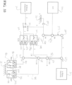
- FIGS 34A through 36 block diagrams of the example embodiments shown in Figures 30 , 32 and 33 are shown. These drawings represent how a transmission 10 would be laid out in design.
- the block diagram represents the transmission 10 shown in the lever diagram of Figure 30 .
- the block diagram represents the transmission 10 shown in the lever diagram of Figure 33 but with two two-way clutches instead of a three-way clutch.
- the block diagram represents the transmission 10 shown in the lever diagram of Figure 32 .
- Figure 36 the block diagram represents the transmission 10 shown in the lever diagram of Figure 33 .
- the transmission 10 is modular in that it can be configured differently while maintaining almost all of the content inside the transmission housing 16 the same.
- the design of the transmission 10 allows it to be scaled up to handle larger ranges of torques based on the host vehicle into which the transmission 10 will be installed.
- the first input shaft 44 is the only input shaft.
- This embodiment only uses one input from the first motor 12 (A-Motor). In a sense, this is the most basic configuration of the transmission 10.
- the transmission has two input shafts 44, 126.
- the first input shaft 44 has an outer diameter 194 and the second input shaft 126 has inner diameter 196, with the outer diameter 194 of the first input shaft 44 being less than the inner diameter 196 of the second input shaft 126.
- the first input shaft 44 extends through the second input shaft 126.
- the second input shaft 126 is a pocket plate.
- the second controllable clutch 142 K24
- the housing cap 20 can be one of several housing caps 20 to be used. Each housing cap 20 is configured to be mounted to the transmission housing 16 whereby the housing cap 20 provides for a different operational configuration. Referring to Figure 39 , the housing cap 20 is extends out further away from the transmission housing 16 more than the housing cap 20 of Figure 38 . This is because the housing cap 20 of Figure 39 houses a gearset 200 to be used as a torque multiplier. Because the transmission 10 is modular, the additional torque multiplier 200 can be added to the transmission 10 and the transmission 10 can be interchangeable between a version that has a torque multiplying gearset 200 ( Figure 39 ) and a version that is supplied without a torque multiplying gearset 200 ( Figure 38 ).
Landscapes
- Engineering & Computer Science (AREA)
- Mechanical Engineering (AREA)
- General Engineering & Computer Science (AREA)
- Chemical & Material Sciences (AREA)
- Combustion & Propulsion (AREA)
- Transportation (AREA)
- Structure Of Transmissions (AREA)
- Hybrid Electric Vehicles (AREA)
Claims (9)
- Getriebebaugruppe (10), die Folgendes umfasst:ein Getriebegehäuse (16),einen ersten Ring-Träger-/Ring-Träger-Zahnradsatz (46), der ein erstes Sonnenrad (52), einen ersten Träger (54) und ein erstes Hohlrad (56) einschließt, die innerhalb des Getriebegehäuses (16) angeordnet sind,einen zweiten Ring-Träger-/Ring-Träger-Zahnradsatz (50), der ein zweites Sonnenrad (60), einen zweiten Träger (62) und ein zweites Hohlrad (64) einschließt, die angrenzend an den ersten Ring-Träger-/Ring-Träger-Zahnradsatz (46) innerhalb des Getriebegehäuses (16) angeordnet sind,eine Abtriebswelle (26), die mit dem ersten Hohlrad (56) des ersten Ring-Träger-/Ring-Träger-Zahnradsatzes (46) und dem zweiten Träger (62) des zweiten Ring-Träger-/Ring-Träger-Zahnradsatzes (50) verbunden ist,eine erste Antriebswelle (44), die mit dem zweiten Sonnenrad (60) des zweiten Ring-Träger-/Ring-Träger-Zahnradsatzes (50) verbunden ist,eine erste steuerbare Kupplung (140), die mit dem ersten Sonnenrad (52) des ersten Ring-Träger-/Ring-Träger-Zahnradsatzes (46) verbunden ist,eine zweite Abtriebswelle (126), die derart mit der ersten steuerbaren Kupplung (140) verbunden ist, dass die erste steuerbare Kupplung (140) die zweite Antriebswelle (126) selektiv mit dem ersten Sonnenrad (52) des ersten Ring-Träger-/Ring-Träger-Zahnradsatzes (46) koppelt,eine zweite steuerbare Kupplung (142), welche die zweite Antriebswelle (126) durch das erste Hohlrad (56) des ersten Ring-Träger-/Ring-Träger-Zahnradsatzes (46) und den zweiten Träger (62) des zweiten Ring-Träger-/Ring-Träger-Zahnradsatzes (50) selektiv mit der Abtriebswelle (26) koppelt,eine erste steuerbare Bremse (76), die das erste Sonnenrad (52) selektiv mit dem Getriebegehäuse (16) koppelt, undeine zweite steuerbare Bremse (92), die den ersten Träger (54) des ersten Ring-Träger-/Ring-Träger-Zahnradsatzes (46) und das zweite Hohlrad (64) des zweiten Ring-Träger-/Ring-Träger-Zahnradsatzes (50) selektiv derart mit dem Getriebegehäuse (16) koppelt, dass die erste und die zweite steuerbare Kupplung (140, 142) und die erste und die zweite steuerbare Bremse (76, 92) das Drehmoment der Abtriebswelle (26) in Abhängigkeit von Kräften, welche die erste und die zweite Antriebswelle (44, 126) antreiben, regeln.
- Getriebebaugruppe (10) nach Anspruch 1, wobei das erste Hohlrad (56) des ersten Ring-Träger-/Ring-Träger-Zahnradsatzes (46) mit dem zweiten Träger (62) des zweiten Ring-Träger-/Ring-Träger-Zahnradsatzes (50) verbunden ist und der erste Träger (54) des ersten Ring-Träger-/Ring-Träger-Zahnradsatzes (46) mit dem zweiten Hohlrad (64) des zweiten Ring-Träger-/Ring-Träger-Zahnradsatzes (50) verbunden ist, um eine Verknüpfung zu bilden, die durch vier Knoten definiert wird.
- Getriebebaugruppe (10) nach Anspruch 2, wobei die erste steuerbare Bremse (76) sperrend gesteuert wird, um einen Zustand zu verändern, um ein gewünschtes Übersetzungsverhältnis für die Getriebebaugruppe (10) aufrechtzuerhalten.
- Getriebebaugruppe (10) nach Anspruch 3, wobei die erste steuerbare Bremse (76) unabhängig in zwei Richtungen steuerbar ist.
- Getriebebaugruppe (10) nach Anspruch 1, wobei die erste Antriebswelle (44) einen Außendurchmesser (194) definiert und die zweite Antriebswelle (126) einen Innendurchmesser (196), größer als der Außendurchmesser (194) der ersten Antriebswelle (44), definiert.
- Getriebebaugruppe (10) nach Anspruch 5, wobei sich die erste Antriebswelle (44) durch die zweite Antriebswelle (126) erstreckt.
- Getriebebaugruppe (10) nach Anspruch 1, wobei der erste und der zweite Ring-Träger-/Ring-Träger-Zahnradsatz (46, 50) miteinander gekoppelt sind, wobei sie eine Ring-Träger-/Ring-Träger-Zahnradsatz-Konfiguration bilden, die durch eine Vier-Knoten-Verknüpfung definiert werden kann.
- Getriebebaugruppe (10) nach Anspruch 7, wobei die Ring-Träger-/Ring-Träger-Zahnradsatz-Konfiguration den ersten Träger (54), der mit dem zweiten Hohlrad (64) gekoppelt ist, und das erste Hohlrad (56), das mit dem zweiten Träger (62) gekoppelt ist, einschließt.
- Getriebebaugruppe (10) nach Anspruch 1, wobei die erste steuerbare Kupplung (140) die erste Antriebswelle (126) mit der Abtriebswelle (26) koppelt.
Applications Claiming Priority (4)
| Application Number | Priority Date | Filing Date | Title |
|---|---|---|---|
| US201962817549P | 2019-03-12 | 2019-03-12 | |
| US201962875034P | 2019-07-17 | 2019-07-17 | |
| US202062982419P | 2020-02-27 | 2020-02-27 | |
| PCT/US2020/022328 WO2020186023A1 (en) | 2019-03-12 | 2020-03-12 | Transmission assembly and method of using same |
Publications (4)
| Publication Number | Publication Date |
|---|---|
| EP3938680A1 EP3938680A1 (de) | 2022-01-19 |
| EP3938680A4 EP3938680A4 (de) | 2023-04-05 |
| EP3938680B1 true EP3938680B1 (de) | 2025-07-02 |
| EP3938680C0 EP3938680C0 (de) | 2025-07-02 |
Family
ID=72427663
Family Applications (1)
| Application Number | Title | Priority Date | Filing Date |
|---|---|---|---|
| EP20770770.4A Active EP3938680B1 (de) | 2019-03-12 | 2020-03-12 | Getriebebaugruppe und verfahren zur verwendung davon |
Country Status (3)
| Country | Link |
|---|---|
| EP (1) | EP3938680B1 (de) |
| CN (1) | CN113474578B (de) |
| WO (1) | WO2020186023A1 (de) |
Families Citing this family (1)
| Publication number | Priority date | Publication date | Assignee | Title |
|---|---|---|---|---|
| WO2022118212A1 (en) * | 2020-12-02 | 2022-06-09 | Involution Technologies Limited | Motor-gearbox arrangement |
Family Cites Families (23)
| Publication number | Priority date | Publication date | Assignee | Title |
|---|---|---|---|---|
| US7427252B2 (en) * | 2005-10-31 | 2008-09-23 | Gm Global Technology Operations, Inc. | Electrically variable transmission with input split mode and compound split modes |
| DE102006006645A1 (de) * | 2006-02-14 | 2007-08-23 | Zf Friedrichshafen Ag | Mehrstufengetriebe |
| DE102006006641A1 (de) * | 2006-02-14 | 2007-08-30 | Zf Friedrichshafen Ag | Mehrstufengetriebe |
| CN101265958B (zh) * | 2007-06-07 | 2010-11-17 | 黄庆培 | 多级变速器 |
| US7914414B2 (en) * | 2007-11-06 | 2011-03-29 | GM Global Technology Operations LLC | Multi-speed transmission |
| KR100892804B1 (ko) * | 2007-11-30 | 2009-04-10 | 현대 파워텍 주식회사 | 자동 변속기의 파워 트레인 |
| KR101199103B1 (ko) * | 2009-04-02 | 2012-11-08 | 현대자동차주식회사 | 하이브리드 차량용 동력전달장치 |
| CN101649889A (zh) * | 2009-06-23 | 2010-02-17 | 奇瑞汽车股份有限公司 | 车用六档变速器及其传动系统 |
| KR101106232B1 (ko) * | 2010-06-29 | 2012-01-20 | 현대 파워텍 주식회사 | 자동변속기 |
| KR101234655B1 (ko) * | 2010-11-24 | 2013-02-19 | 기아자동차주식회사 | 차량용 무단변속기 |
| DE102011003264A1 (de) * | 2011-01-27 | 2012-08-02 | Zf Friedrichshafen Ag | Getriebevorrichtung eines Antriebsstrangs zum Verteilen des Antriebsmomentes zwischen zwei Antriebswellen |
| KR101283039B1 (ko) * | 2011-06-09 | 2013-07-05 | 현대자동차주식회사 | 하이브리드 차량의 동력전달장치 |
| US8562480B1 (en) * | 2012-06-01 | 2013-10-22 | GM Global Technology Operations LLC | Vehicle drivetrain with an electric torque converter |
| AT512915B1 (de) * | 2012-11-08 | 2013-12-15 | Avl List Gmbh | Mehrstufengetriebe für Kraftfahrzeuge |
| JP2017537285A (ja) * | 2014-12-08 | 2017-12-14 | ダナ リミテッド | 3モードの前輪駆動および後輪駆動用の遊星機構無段変速機 |
| US9643481B2 (en) * | 2015-05-20 | 2017-05-09 | Ford Global Technologies, Llc | Multi-mode powersplit hybrid transmission |
| KR20170062313A (ko) * | 2015-11-27 | 2017-06-07 | 현대자동차주식회사 | 자동차의 동력전달장치 |
| KR101846897B1 (ko) * | 2016-03-18 | 2018-04-09 | 현대자동차 주식회사 | 차량용 자동변속기의 유성기어트레인 |
| JP6512160B2 (ja) * | 2016-04-19 | 2019-05-15 | トヨタ自動車株式会社 | 車両用動力伝達装置の制御装置 |
| CN105840749B (zh) * | 2016-05-29 | 2018-01-02 | 无锡商业职业技术学院 | 一种单双级行星齿轮组合式四挡自动变速器 |
| CN106939929A (zh) * | 2017-05-19 | 2017-07-11 | 福建万润新能源科技有限公司 | 一种单齿圈干摩擦外控三挡变速器 |
| CN109185404B (zh) * | 2018-11-20 | 2020-12-11 | 北京航空航天大学 | 电动车用多挡自动变速装置 |
| CN109340328B (zh) * | 2018-12-10 | 2023-01-10 | 肇庆学院 | 多级变速器 |
-
2020
- 2020-03-12 WO PCT/US2020/022328 patent/WO2020186023A1/en not_active Ceased
- 2020-03-12 EP EP20770770.4A patent/EP3938680B1/de active Active
- 2020-03-12 CN CN202080016074.8A patent/CN113474578B/zh active Active
Also Published As
| Publication number | Publication date |
|---|---|
| CN113474578A (zh) | 2021-10-01 |
| EP3938680A4 (de) | 2023-04-05 |
| CN113474578B (zh) | 2024-07-19 |
| EP3938680A1 (de) | 2022-01-19 |
| WO2020186023A1 (en) | 2020-09-17 |
| EP3938680C0 (de) | 2025-07-02 |
Similar Documents
| Publication | Publication Date | Title |
|---|---|---|
| US10711867B1 (en) | Transmission assembly and method of using same | |
| US7699735B2 (en) | Electrically-variable transmission having two forward low range electrically-variable modes and a reverse electrically-variable mode | |
| US7256510B2 (en) | Hybrid electro-mechanical transmission with single motor/generator and method of control | |
| US7416501B2 (en) | Single range electrically variable transmission with lockup clutch and method of operation | |
| CN101273217B (zh) | 具有两个行星齿轮组、两个固定互连件和离合输入的多模式电动变速器 | |
| AU2004265350B2 (en) | Electro-mechanical continuously variable transmission | |
| CN101283200B (zh) | 具有两个或三个行星齿轮组及两个或三个固定的互连部件的电动变速器 | |
| KR100926059B1 (ko) | 3개의 유성 기어 세트와 3개의 고정된 상호연결을 갖는고정 전기 가변 트랜스미션 | |
| US7179187B2 (en) | Electrically variable transmission having three interconnected planetary gear sets, two clutches and two brakes | |
| EP3057818B1 (de) | Stufenloses elektrisches getriebe | |
| US6540631B2 (en) | Electrically variable transmission with variable input power split and independent shifting | |
| KR20070110552A (ko) | 2개의 유성 기어 세트와 2개의 고정된 상호연결을 갖는전기 가변 트랜스미션 | |
| WO2007061511A2 (en) | Multi-mode electrically variable transmissions having two planetary gear sets with one fixed interconnection | |
| WO2006073677A2 (en) | Electrically variable transmission having three interconnected planetary gear sets two clutches and at least two brakes | |
| CN101258337B (zh) | 具有两个行星齿轮组及一个固定的互连部件的电动变速器 | |
| WO2006115613A2 (en) | Electrically variable transmission having two planetary gearsets | |
| CN101321971A (zh) | 电动无级变速器 | |
| CN101356388B (zh) | 具有三个互连的齿轮组的电动变速传动装置 | |
| CN103402804A (zh) | 变速器单元 | |
| CN112428813A (zh) | 串并联混合动力传动装置 | |
| US20190105980A1 (en) | Dual electric machine co-drive system with selective booster of electric machine | |
| US7261657B2 (en) | Electrically variable transmission having three interconnected planetary gear sets and fixed input | |
| US7690459B2 (en) | Hybrid electric vehicle and powertrain | |
| EP3938680B1 (de) | Getriebebaugruppe und verfahren zur verwendung davon | |
| CN108656937B (zh) | 一种混合电驱动装置 |
Legal Events
| Date | Code | Title | Description |
|---|---|---|---|
| STAA | Information on the status of an ep patent application or granted ep patent |
Free format text: STATUS: THE INTERNATIONAL PUBLICATION HAS BEEN MADE |
|
| PUAI | Public reference made under article 153(3) epc to a published international application that has entered the european phase |
Free format text: ORIGINAL CODE: 0009012 |
|
| STAA | Information on the status of an ep patent application or granted ep patent |
Free format text: STATUS: REQUEST FOR EXAMINATION WAS MADE |
|
| 17P | Request for examination filed |
Effective date: 20211008 |
|
| AK | Designated contracting states |
Kind code of ref document: A1 Designated state(s): AL AT BE BG CH CY CZ DE DK EE ES FI FR GB GR HR HU IE IS IT LI LT LU LV MC MK MT NL NO PL PT RO RS SE SI SK SM TR |
|
| DAV | Request for validation of the european patent (deleted) | ||
| DAX | Request for extension of the european patent (deleted) | ||
| A4 | Supplementary search report drawn up and despatched |
Effective date: 20230309 |
|
| RIC1 | Information provided on ipc code assigned before grant |
Ipc: F16H 3/66 20060101ALI20230302BHEP Ipc: B60K 6/38 20071001ALI20230302BHEP Ipc: B60K 6/365 20071001ALI20230302BHEP Ipc: B60K 1/02 20060101ALI20230302BHEP Ipc: F16H 3/72 20060101ALI20230302BHEP Ipc: F16H 1/28 20060101ALI20230302BHEP Ipc: F16H 55/32 20060101ALI20230302BHEP Ipc: F16H 3/58 20060101AFI20230302BHEP |
|
| GRAP | Despatch of communication of intention to grant a patent |
Free format text: ORIGINAL CODE: EPIDOSNIGR1 |
|
| STAA | Information on the status of an ep patent application or granted ep patent |
Free format text: STATUS: GRANT OF PATENT IS INTENDED |
|
| INTG | Intention to grant announced |
Effective date: 20250124 |
|
| GRAS | Grant fee paid |
Free format text: ORIGINAL CODE: EPIDOSNIGR3 |
|
| GRAA | (expected) grant |
Free format text: ORIGINAL CODE: 0009210 |
|
| STAA | Information on the status of an ep patent application or granted ep patent |
Free format text: STATUS: THE PATENT HAS BEEN GRANTED |
|
| AK | Designated contracting states |
Kind code of ref document: B1 Designated state(s): AL AT BE BG CH CY CZ DE DK EE ES FI FR GB GR HR HU IE IS IT LI LT LU LV MC MK MT NL NO PL PT RO RS SE SI SK SM TR |
|
| REG | Reference to a national code |
Ref country code: GB Ref legal event code: FG4D |
|
| REG | Reference to a national code |
Ref country code: CH Ref legal event code: EP |
|
| REG | Reference to a national code |
Ref country code: DE Ref legal event code: R096 Ref document number: 602020053844 Country of ref document: DE |
|
| REG | Reference to a national code |
Ref country code: IE Ref legal event code: FG4D |
|
| U01 | Request for unitary effect filed |
Effective date: 20250722 |
|
| U07 | Unitary effect registered |
Designated state(s): AT BE BG DE DK EE FI FR IT LT LU LV MT NL PT RO SE SI Effective date: 20250728 |
|
| PG25 | Lapsed in a contracting state [announced via postgrant information from national office to epo] |
Ref country code: IS Free format text: LAPSE BECAUSE OF FAILURE TO SUBMIT A TRANSLATION OF THE DESCRIPTION OR TO PAY THE FEE WITHIN THE PRESCRIBED TIME-LIMIT Effective date: 20251102 |
|
| PG25 | Lapsed in a contracting state [announced via postgrant information from national office to epo] |
Ref country code: NO Free format text: LAPSE BECAUSE OF FAILURE TO SUBMIT A TRANSLATION OF THE DESCRIPTION OR TO PAY THE FEE WITHIN THE PRESCRIBED TIME-LIMIT Effective date: 20251002 |
|
| PG25 | Lapsed in a contracting state [announced via postgrant information from national office to epo] |
Ref country code: HR Free format text: LAPSE BECAUSE OF FAILURE TO SUBMIT A TRANSLATION OF THE DESCRIPTION OR TO PAY THE FEE WITHIN THE PRESCRIBED TIME-LIMIT Effective date: 20250702 |
|
| PG25 | Lapsed in a contracting state [announced via postgrant information from national office to epo] |
Ref country code: GR Free format text: LAPSE BECAUSE OF FAILURE TO SUBMIT A TRANSLATION OF THE DESCRIPTION OR TO PAY THE FEE WITHIN THE PRESCRIBED TIME-LIMIT Effective date: 20251003 |
|
| PG25 | Lapsed in a contracting state [announced via postgrant information from national office to epo] |
Ref country code: CZ Free format text: LAPSE BECAUSE OF FAILURE TO SUBMIT A TRANSLATION OF THE DESCRIPTION OR TO PAY THE FEE WITHIN THE PRESCRIBED TIME-LIMIT Effective date: 20250702 |
|
| PG25 | Lapsed in a contracting state [announced via postgrant information from national office to epo] |
Ref country code: PL Free format text: LAPSE BECAUSE OF FAILURE TO SUBMIT A TRANSLATION OF THE DESCRIPTION OR TO PAY THE FEE WITHIN THE PRESCRIBED TIME-LIMIT Effective date: 20250702 |
|
| PG25 | Lapsed in a contracting state [announced via postgrant information from national office to epo] |
Ref country code: RS Free format text: LAPSE BECAUSE OF FAILURE TO SUBMIT A TRANSLATION OF THE DESCRIPTION OR TO PAY THE FEE WITHIN THE PRESCRIBED TIME-LIMIT Effective date: 20251002 |
|
| PG25 | Lapsed in a contracting state [announced via postgrant information from national office to epo] |
Ref country code: ES Free format text: LAPSE BECAUSE OF FAILURE TO SUBMIT A TRANSLATION OF THE DESCRIPTION OR TO PAY THE FEE WITHIN THE PRESCRIBED TIME-LIMIT Effective date: 20250702 |
|
| PG25 | Lapsed in a contracting state [announced via postgrant information from national office to epo] |
Ref country code: SM Free format text: LAPSE BECAUSE OF FAILURE TO SUBMIT A TRANSLATION OF THE DESCRIPTION OR TO PAY THE FEE WITHIN THE PRESCRIBED TIME-LIMIT Effective date: 20250702 |
|
| PGFP | Annual fee paid to national office [announced via postgrant information from national office to epo] |
Ref country code: GB Payment date: 20260327 Year of fee payment: 7 |
|
| PG25 | Lapsed in a contracting state [announced via postgrant information from national office to epo] |
Ref country code: SK Free format text: LAPSE BECAUSE OF FAILURE TO SUBMIT A TRANSLATION OF THE DESCRIPTION OR TO PAY THE FEE WITHIN THE PRESCRIBED TIME-LIMIT Effective date: 20250702 |