EP3937586B1 - Kanaldetektierungsverfahren, kanalübertragungsverfahren, endgerät und netzgerät - Google Patents
Kanaldetektierungsverfahren, kanalübertragungsverfahren, endgerät und netzgerät Download PDFInfo
- Publication number
- EP3937586B1 EP3937586B1 EP19921405.7A EP19921405A EP3937586B1 EP 3937586 B1 EP3937586 B1 EP 3937586B1 EP 19921405 A EP19921405 A EP 19921405A EP 3937586 B1 EP3937586 B1 EP 3937586B1
- Authority
- EP
- European Patent Office
- Prior art keywords
- occasion
- time
- pusch
- rach
- network device
- Prior art date
- Legal status (The legal status is an assumption and is not a legal conclusion. Google has not performed a legal analysis and makes no representation as to the accuracy of the status listed.)
- Active
Links
Images


Classifications
-
- H—ELECTRICITY
- H04—ELECTRIC COMMUNICATION TECHNIQUE
- H04W—WIRELESS COMMUNICATION NETWORKS
- H04W74/00—Wireless channel access
- H04W74/08—Non-scheduled access, e.g. ALOHA
- H04W74/0833—Random access procedures, e.g. with 4-step access
-
- H—ELECTRICITY
- H04—ELECTRIC COMMUNICATION TECHNIQUE
- H04L—TRANSMISSION OF DIGITAL INFORMATION, e.g. TELEGRAPHIC COMMUNICATION
- H04L27/00—Modulated-carrier systems
- H04L27/26—Systems using multi-frequency codes
- H04L27/2601—Multicarrier modulation systems
- H04L27/2602—Signal structure
- H04L27/26025—Numerology, i.e. varying one or more of symbol duration, subcarrier spacing, Fourier transform size, sampling rate or down-clocking
-
- H—ELECTRICITY
- H04—ELECTRIC COMMUNICATION TECHNIQUE
- H04L—TRANSMISSION OF DIGITAL INFORMATION, e.g. TELEGRAPHIC COMMUNICATION
- H04L5/00—Arrangements affording multiple use of the transmission path
- H04L5/003—Arrangements for allocating sub-channels of the transmission path
- H04L5/0053—Allocation of signalling, i.e. of overhead other than pilot signals
-
- H—ELECTRICITY
- H04—ELECTRIC COMMUNICATION TECHNIQUE
- H04W—WIRELESS COMMUNICATION NETWORKS
- H04W52/00—Power management, e.g. Transmission Power Control [TPC] or power classes
- H04W52/02—Power saving arrangements
- H04W52/0209—Power saving arrangements in terminal devices
- H04W52/0225—Power saving arrangements in terminal devices using monitoring of external events, e.g. the presence of a signal
- H04W52/0248—Power saving arrangements in terminal devices using monitoring of external events, e.g. the presence of a signal dependent on the time of the day, e.g. according to expected transmission activity
-
- H—ELECTRICITY
- H04—ELECTRIC COMMUNICATION TECHNIQUE
- H04W—WIRELESS COMMUNICATION NETWORKS
- H04W72/00—Local resource management
- H04W72/04—Wireless resource allocation
- H04W72/044—Wireless resource allocation based on the type of the allocated resource
- H04W72/0446—Resources in time domain, e.g. slots or frames
-
- H—ELECTRICITY
- H04—ELECTRIC COMMUNICATION TECHNIQUE
- H04W—WIRELESS COMMUNICATION NETWORKS
- H04W72/00—Local resource management
- H04W72/12—Wireless traffic scheduling
- H04W72/1263—Mapping of traffic onto schedule, e.g. scheduled allocation or multiplexing of flows
- H04W72/1268—Mapping of traffic onto schedule, e.g. scheduled allocation or multiplexing of flows of uplink data flows
-
- H—ELECTRICITY
- H04—ELECTRIC COMMUNICATION TECHNIQUE
- H04W—WIRELESS COMMUNICATION NETWORKS
- H04W72/00—Local resource management
- H04W72/20—Control channels or signalling for resource management
- H04W72/23—Control channels or signalling for resource management in the downlink direction of a wireless link, i.e. towards a terminal
- H04W72/231—Control channels or signalling for resource management in the downlink direction of a wireless link, i.e. towards a terminal the control data signalling from the layers above the physical layer, e.g. RRC or MAC-CE signalling
-
- H—ELECTRICITY
- H04—ELECTRIC COMMUNICATION TECHNIQUE
- H04W—WIRELESS COMMUNICATION NETWORKS
- H04W74/00—Wireless channel access
- H04W74/002—Transmission of channel access control information
- H04W74/004—Transmission of channel access control information in the uplink, i.e. towards network
-
- H—ELECTRICITY
- H04—ELECTRIC COMMUNICATION TECHNIQUE
- H04W—WIRELESS COMMUNICATION NETWORKS
- H04W74/00—Wireless channel access
- H04W74/08—Non-scheduled access, e.g. ALOHA
- H04W74/0833—Random access procedures, e.g. with 4-step access
- H04W74/0836—Random access procedures, e.g. with 4-step access with 2-step access
Definitions
- the present disclosure relates to the field of wireless communication technologies, and more particularly, to a method for channel detection, a method for channel transmission, a terminal device and a network device.
- random access includes a first type of random access and a second type of random access.
- the first type of random access there needs to perform two information interactions between a terminal device and a network device, that is, the terminal device transmits a message (Msg) A to the network device, and the network device transmits a MsgB to the terminal device.
- the first type of random access is also referred to as 2-steps random access (2-steps RACH).
- the second type of random access there needs to perform four information interactions between the terminal device and the network device.
- the second type of random access is also referred to as 4-steps random access (4-steps RACH).
- the network device In the first type of random access, since a preamble and a Physical Uplink Shared Channel (PUSCH) are included in MsgA, the network device needs to decode PUSCH. Therefore, regarding that the terminal device detects a channel carrying the MsgB at what time-frequency position or the network device transmits the channel carrying the MsgB at what time-frequency position to improve the performance of a system, there is no effective solution at present.
- Related technology is known from 3GPP TS 38.213 V15.5.0, 27.03.2019 .
- a terminal device determines a starting position of a time window for detecting a channel carrying a MsgB
- a network device determines a starting position of a time window for transmitting a channel carrying the MsgB.
- Starting to transmit a channel or to detect a channel at the starting position can reduce the power consumption of the terminal device and improve the scheduling performance of the network device.
- a method for channel detection includes that: a terminal device determines a starting position of a time window for channel detection based on a message transmitted by a network device, the starting position being positioned after a time delay which is after an end of an RACH occasion or a PUSCH occasion; herein the time delay is at least two symbols, or the time delay is relevant to a time-domain relationship between the RACH occasion and the PUSCH occasion.
- a network device determines a starting position of a time window for channel transmission, the starting position being positioned after a time delay which is after an end of an RACH occasion or a PUSCH occasion; herein the time delay is at least two symbols, or the time delay is relevant to a time-domain relationship between the RACH occasion and the PUSCH occasion.
- a terminal device including a first processing unit.
- the first processing unit is configured to determine a starting position of a time window for channel detection based on a message transmitted by a network device, the starting position being positioned after a time delay which is after an end of an RACH occasion or a PUSCH occasion; herein the time delay is at least two symbols, or the time delay is relevant to a time-domain relationship between the RACH occasion and the PUSCH occasion.
- a network device including a second processing unit.
- the second processing unit is configured to determine a starting position of a time window for channel transmission, the starting position being positioned after a time delay which is after an end of an RACH occasion or a PUSCH occasion; herein the time delay is at least two symbols, or the time delay is relevant to a time-domain relationship between the RACH occasion and the PUSCH occasion.
- a method for channel detection includes that: a terminal device determines a starting position of a time window for channel detection based on a message transmitted by a network device, or the network device determines a starting position of a time window for channel transmission; the starting position is positioned after a time delay which is after an end of an RACH occasion or a PUSCH occasion; the time delay is at least two symbols, or the time delay is relevant to a time-domain relationship between the RACH occasion and the PUSCH occasion.
- the network device cannot complete the reception and decoding of the MsgA and the encoding of the MsgB within one symbol, so that the network device cannot transmit the MsgB at the early stage of a receiving window for the MsgB, and can transmit the MsgB only at the later stage of the receiving window for the MsgB, thereby causing a restriction on scheduling of the network device.
- the receiving window for the MsgB is opened prematurely by the terminal device, and the network device cannot transmit the MsgB in time, thereby increasing the power consumption of the terminal device.
- the terminal device can flexibly set the starting position of the time window for channel detection according to the time-domain relationship between the RACH occasion and the PUSCH occasion, thereby further improving the performance of the system.
- the processing flow of the second type of random access includes the following four steps.
- a terminal device transmits the random access preamble to a network device through a message 1 (Msgl).
- the terminal device transmits a selected preamble on a selected Physical Random Access Channel (PRACH) time-domain resource.
- PRACH Physical Random Access Channel
- the network device can estimate the uplink timing and the size of the uplink grant that is required for the terminal device to transmit a Msg3.
- the network device transmits an RAR message to the terminal device through a Msg2 after having detected that the terminal device transmits the preamble, so as to inform the terminal device of uplink resource information that may be used when transmitting the Msg3, allocate a temporary Radio Network Temporary Identifier (RNTI) to the terminal device, and provide a time advance command for the terminal device.
- RAR Radio Network Temporary Identifier
- the terminal device transmits the Msg3 in the uplink resource specified in the RAR message.
- the Msg3 is mainly configured to inform the network device that the RACH procedure is triggered by what event. For example, if it is an initial random access event, a terminal device identifier (ID) and an establishment cause are carried in the Msg3. If it is a Radio Resource Control (RRC) re-establishment event, the terminal device identifier and the establishment cause in the connected state are carried in the Msg3. If it is in an RRC connected state, the Msg3 includes a Cell-RNTI (C-RNTI) MAC CE.
- C-RNTI Cell-RNTI
- the ID carried in the Msg3 may make a contention conflict resolved in S 104.
- the network device transmits a Msg4 including a contention resolution message to the terminal device, and allocates uplink transmission resources to the terminal device at the same time.
- the terminal device detects whether the specific temporary identifier for the terminal device transmitted by the terminal device in the Msg3 is included in the contention resolution message transmitted by the base station. If the specific temporary identifier for the terminal device transmitted by the terminal device in the Msg3 is included in the contention resolution message transmitted by the base station, it indicates that the random access procedure of the terminal device is successful. If the specific temporary identifier for the terminal device transmitted by the terminal device in the Msg3 is not included in the contention resolution message transmitted by the base station, it is considered that the random access procedure fails, and the terminal device needs to initiate the random access procedure again from the first step.
- resource information for transmitting the Msg1 is obtained through RACH resource configuration.
- RACH resources configured for access terminal devices, including 256 configurations, are defined.
- the RACH resource configuration information used by a cell is indicated to the connected terminal device in a system message.
- the RACH resource configuration includes a preamble format, a period, a radio frame offset, a subframe number within a radio frame, a starting symbol within a subframe, a number of PRACH slots within a subframe, a number of RACH occasion within a PRACH slot, and an RACH occasion duration.
- Time-domain information, frequency-domain information, and code-domain information of the PRACH resource can be determined through the RACH resource configuration.
- the network device indicates, through the system message, the configuration information, i.e., ra-SearchSpace, of the search space of a Physical Downlink Control Channel (PDCCH) that needs to be received by the terminal device for RAR reception.
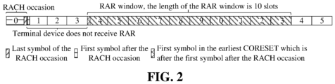
- the terminal device receives the RAR corresponding to the Msg1 by detecting the PDCCH corresponding to the Msg1 in the search space within one RAR time window.
- a PDCCH carrying the Downlink control information (DCI) format 1-0 is scrambled by the Random Access RNTI (RA-RNTI) and transmitted to the terminal device transmitting the Msg1.
- the search space configured through ra-SearchSpace is Type1-PDCCH common search space.
- the RAR time window is configured through a high level parameter ra-ResponseWindow.
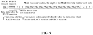
- the RAR time window starts at the first symbol of the nearest Control Resource Set (CORESET) which is after at least one symbol after the last symbol of the RACH occasion, and the CORESET is a CORESET configured by the ra-SearchSpace configuration information.
- CORESET Control Resource Set
- the configuration information for RAR time window is as follows:
- the window size of the RAR time window is 10 slots and the subcarrier spacing is 15kHz.
- the RAR time window starts at the first symbol in the earliest CORESET which is after at least one symbol after the last symbol of the PRACH occasion, and the CORESET is a time-frequency resource configured for the Typel-PDCCH common search space and configured for receiving the PDCCH.
- the processing flow of the first type of random access includes the following two steps.
- a terminal device transmits a MsgA to a network device.
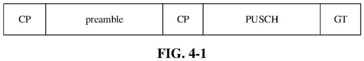
- the MsgA consists of a preamble and a payload.
- the preamble is the same as the preamble in the second type of random access, which is transmitted on PRACH resources; information carried in the payload is the same as the information of the Msg3 in the second type of random access, such as RRC signaling when the RRC is in the idle state and C-RNTI MAC CE when the RRC is in the connected state.
- the payload may be transmitted by the PUSCH. It can be understood that the MsgA includes the content of the Msg1 and the Msg3 in the second type of random access.
- the terminal device receives a MsgB transmitted by the network device.
- the MsgB includes the content of the Msg2 and the Msg4 in a second type of random access, and the MsgB needs to be transmitted by the PDCCH and the PDSCH.
- the RACH occasion in which the preamble is transmitted there is a correspondence between the RACH occasion in which the preamble is transmitted and the PUSCH occasion in which the PUSCH is transmitted.
- the correspondence may be predefined or indicated by the network device.
- the time sequential relationship between the RACH occasion and the PUSCH occasion may be, as illustrated in FIG. 4-1 , that the RACH occasion precedes the PUSCH occasion, or, as illustrated in FIG. 4-2 , that the PUSCH occasion precedes the RACH occasion.
- the terminal device After transmitting the MsgA, the terminal device needs to determine whether the MsgA is successfully received by the network device according to the result of the received MsgB, so as to decide whether to make a subsequent retransmission of the MsgA. Since the PUSCH is added into the MsgA, the network device also needs to receive and decode the PUSCH and determine the content of the MsgB according to the content of the PUSCH in addition to receiving the preamble in the MsgA. According to the method for determining the starting position of the RAR time window in the related art, it is possible that the network device cannot complete the reception and the decoding of the MsgA, and the encoding of the MsgB.
- the network device cannot transmit the MsgB at the early stage of the MsgB time window, but can transmit the MsgB only at the later stage of the MsgB time window, which restricts the scheduling of the network device.
- the MsgB time window is opened prematurely, and the network device cannot transmit the MsgB in time, thereby increasing the power consumption of the terminal device.
- the present disclosure provides a method for channel transmission, and the method for channel transmission according to the embodiments of the present disclosure can be applied to various types of communication systems, such as a Global System of Mobile communication (GSM) system, a Code Division Multiple Access (CDMA) system, a Wideband Code Division Multiple Access (WCDMA) system, a General Packet Radio Service (GPRS), a Long Term Evolution (LTE) system, a Frequency Division Duplex (FDD) system, a Time Division Duplex (TDD), a Universal Mobile Telecommunication System (UMTS), a Worldwide Interoperability for Microwave Access (WiMAX) communication system, or an 5G system.
- GSM Global System of Mobile communication
- CDMA Code Division Multiple Access
- WCDMA Wideband Code Division Multiple Access
- GPRS General Packet Radio Service
- LTE Long Term Evolution
- FDD Frequency Division Duplex
- TDD Time Division Duplex
- UMTS Universal Mobile Telecommunication System
- WiMAX Worldwide Interoperability for Microwave Access
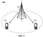
- the communication system 100 may include a network device 110, which may be a device that communicates with a terminal device 120 (or referred to as a communication terminal, a terminal).
- the network device 110 may provide communication coverage for a particular geographic area and may communicate with terminal devices located within the coverage area.
- the network device 110 may be a Base Transceiver Station (BTS) in a GSM system or a CDMA system, or may be a NodeB (NB) in a WCDMA system, or may be an Evolutional Node B (eNB or eNodeB) in an LTE system, or may be a radio controller in a Cloud Radio Access Network (CRAN), or the network device may be a mobile switching center, a relay station, an access point, a vehicle-mounted device, a wearable device, a hub, a switch, a bridge, a router, a network-side device in a 5G network, a network device in a Public Land Mobile Network (PLMN), or the like.
- BTS Base Transceiver Station
- NB NodeB
- eNB or eNodeB Evolutional Node B
- LTE Long Term Evolutional Node B
- CRAN Cloud Radio Access Network
- the network device may be a mobile switching center, a relay station, an access point, a vehicle
- the communication system 100 also includes at least one terminal device 120 located within coverage of the network device 110.
- the "terminal device” includes, but is not limited to be connected: via a wired line, such as via a Public Switched Telephone Networks (PSTN), a Digital Subscriber Line (DSL), a digital cable, a direct cable connection; and/or another data connection/network; and/or via a wireless interface, for example, for a cellular network, a Wireless Local Area Network (WLAN), a digital television network such as a DVB-H network, a satellite network, a AM-FM broadcast transmitter; and/or means of another terminal device arranged to receive/transmit communication signals; and/or an Internet of Things (IoT) device.
- PSTN Public Switched Telephone Networks
- DSL Digital Subscriber Line
- WLAN Wireless Local Area Network
- IoT Internet of Things
- the terminal device configured to communicate through a wireless interface may be referred to as a "radio communication terminal", a “radio terminal” or a “mobile terminal”.
- the mobile terminal include, but are not limited to: a satellite or cellular telephone; a Personal Communications System (PCS) terminal that may combine a cellular radio telephone with data processing, facsimile, and data communication capabilities; a Personal Digital Assistant (PDA) that may include a radio telephone, a pager, Internet/Intranet access, a Web browser, a notebook, a calendar, and/or a Global Positioning System (GPS) receiver; and conventional laptop and/or palmtop receivers or other electronic devices including radio telephone transceivers.
- PCS Personal Communications System
- GPS Global Positioning System
- the terminal device may refer to an access terminal, User Equipment (UE), a user unit, a user station, a mobile station, a mobile radio station, a remote station, a remote terminal, a mobile device, a user terminal, a terminal, a radio communication device, a user agent, or a user device.
- UE User Equipment
- the access terminal may be a cellular telephone, a cordless telephone, a Session Initiation Protocol (SIP) telephone, a Wireless Local Loop (WLL) station, a PDA, a handheld device having a radio communication function, a computing device or other processing device connected to a radio modem, an in-vehicle device, a wearable device, a terminal device in a 5G network, a terminal device in the future evolved PLMN, or the like.
- SIP Session Initiation Protocol
- WLL Wireless Local Loop
- D2D Device to Device
- the 5G system or 5G network may also be referred to as an NR system or an NR network.
- FIG. 5 exemplarily illustrates a network device and two terminal devices.
- the communication system 100 may include a plurality of network devices, and another number of terminal devices may be included within the coverage area of each network device, which are not limited by the embodiments of the present disclosure.
- the communication system 100 may further include other network entities such as a network controller, a mobility management entity, and the like, which are not limited by the embodiments of the present disclosure.
- network entities such as a network controller, a mobility management entity, and the like, which are not limited by the embodiments of the present disclosure.
- a device having a communication function in a network/system in the embodiments of the present disclosure may be referred to as a communication device.
- the communication device may include a network device 110 and a terminal device 120 having a communication function.
- the network device 110 and the terminal device 120 may be specific devices described above, and details are not described herein.
- the communication device may also include other devices in the communication system 100, such as network controllers, mobility management entities, and other network entities, which are not limited in the embodiments of the present disclosure.
- An alternative processing flow of a method for channel transmission according to an embodiment of the present disclosure, as illustrated in FIG. 6 includes the following operations.
- a terminal device determines a starting position of a time window for channel detection based on a message transmitted by a network device, the starting position being positioned after a time delay which is after an end of an RACH occasion or a PUSCH occasion; herein the time delay is at least two symbols, or the time delay is relevant to a time-domain relationship between the RACH occasion and the PUSCH occasion.
- the starting position is a starting position of a first symbol of a CORESET after the time delay which is after the end of the RACH occasion, or the starting position is a starting position of a first symbol of a first CORESET after the time delay which is after the end of the PUSCH occasion.
- the CORESET is a CORESET configured for a Typel-PDCCH common search space, and the Typel-PDCCH common search space, the RACH occasion, and the PUSCH occasion are determined by the terminal device according to the message transmitted by the network device.
- the terminal device may directly determine the starting position of the time window for channel detection through the message transmitted by the network device, that is, the network device transmits the starting position to the terminal device after determining the starting position of the time window for channel detection.
- the network device transmits a message to the terminal device, and the terminal device determines the starting position of the time window for channel detection according to the content carried in the message.
- the time delay is a fixed value.
- the time delay may be determined according to at least one of a processing time for PUSCH or a preparation time for PUSCH. Since the processing capabilities of the network devices manufactured by different manufacturers are different, the preparation time for PUSCH and the processing time for PUSCH are determined based on the processing time of the terminal device for PDSCH and the preparation time of the terminal device for PDSCH.
- the processing capability of the terminal device for PDSCH is shown in Table 1 and Table 2 below.
- the preparation capability of the terminal device for PDSCH is shown in Table 3 and Table 4 below.
- ⁇ 0, 1, 2, 3 indicates that the subcarrier spacing of PDSCH or PUSCH is 15KHz, 30KHz, 60KHz, 120KHz, respectively.
- the processing time of the network device for the PUSCH can be estimated.
- a relatively conservative fixed time such as 20 symbols
- the preparation time for PDSCH i.e., for MsgB
- a relatively conservative fixed time such as 36 symbols
- the processing capability of the network device is stronger than that of the terminal device, and the processing capabilities of the devices of respective manufacturers are different.
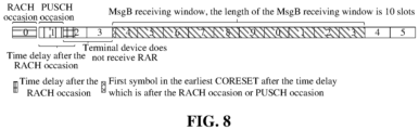
- the starting position of the first symbol of the nearest CORESET after N symbols after the end of the RACH occasion or the PUSCH occasion may be defined as the starting position of the MsgB receiving window.
- the value of N should be greater than the existing fixed time of one symbol to facilitate the reception and decoding of PUSCH in MsgA.
- FIG. 7 a schematic diagram of a starting position of a time window for channel detection is illustrated in FIG. 7 .
- the starting point of the N symbols is a time point of the end of the RACH occasion or a time point of the end of the PUSCH occasion.
- the terminal device When the time delay is a fixed value, before determining the starting position of the time window for channel detection, the terminal device needs to receive a message transmitted by the network device determines an RACH occasion or an PUSCH occasion based on the message transmitted by the network device, and determines a Typel-PDCCH common search space based on the message transmitted by the network device. Then, the starting position of the first symbol of the first CORESET after the time delay after the end of the RACH occasion or the PUSCH occasion is used as the starting position of the time window for channel detection. The terminal device detects the MsgB based on the starting position.
- it can not only meet the processing time of the network device for PUSCH and the preparation time of the network device for PDSCH, but also reduce the power consumption of the terminal device and the implementation complexity of the network device and the terminal device.
- the time delay is a variable value.
- the time delay is determined according to a subcarrier spacing of the PDCCH or a subcarrier spacing of the PUSCH.
- the PDCCH is a PDCCH transmitted in Type-1-PDCCH common search space.
- Different values of ⁇ may correspond to different time delays.
- the values of N1, N2, N3, N4 take into account the time required by the network device for the processing time of PUSCH and the preparation time of the MsgB; the respective values of N1, N2, N3 and N4 may be specified.
- the terminal device Before determining the starting position of the time window for channel detection, the terminal device needs to receive a message transmitted by the network device, determines an RACH occasion or an PUSCH occasion based on the message transmitted by the network device, and determines the PDCCH based on the message transmitted by the network device. Then, the subcarrier spacing of PDCCH or the subcarrier spacing of PUSCH is determined, and the time delay is determined based on the subcarrier spacing of PDCCH or the subcarrier spacing of PUSCH. Finally, the starting position of the first symbol of the first CORESET after the time delay after the end of the RACH occasion or the PUSCH occasion is used as the starting position of the time window for channel detection.
- the terminal device detects the MsgB based on the starting position.
- the time delays can be more matched with the setting of different subcarrier spacings.
- the flexibility of time delay configuration can be increased. In such a manner, it not only meets the processing time of the network device, but also reduces the delay of the terminal device for receiving the MsgB.
- the time-domain relationship between the RACH occasion and the PUSCH occasion is determined by the terminal device according to a message transmitted by the network device, or the time-domain relationship between the RACH occasion and the PUSCH occasion is preset.
- the time-domain relationship between the RACH occasion and the PUSCH occasion includes at least one of: a time sequential relationship between the RACH occasion and the PUSCH occasion; or a time difference between the RACH occasion and the PUSCH occasion.
- the time sequential relationship between the RACH occasion and the PUSCH occasion may be that the RACH occasion precedes the PUSCH occasion, or the PUSCH occasion precedes the RACH occasion.
- the time delays for determining the starting position of the time window for channel detection are different according to the different time sequential relationships between the RACH occasion and the PUSCH occasion. If it is calculated from the time point of the end of the RACH occasion, the required time delays are different for different time sequential relationships between the RACH occasion and the PUSCH occasion. For example, when the PUSCH occasion precedes the RACH occasion, the network device has completed the demodulation of the PUSCH or the reception of the PUSCH at the end of the RACH occasion, such that the processing time required by the network device will be reduced, and the time delay will be reduced.
- the network device needs to further complete the reception and demodulation of the PUSCH at the end of the RACH occasion, such that the processing time required by the network device will be increased, and the time delay will be increased.
- the time delay when the PUSCH occasion is before the RACH occasion is illustrated in FIG. 8 .
- the time delay when the RACH occasion is before the PUSCH occasion is illustrated in FIG. 9 .
- the effect of the time sequential relationship between the RACH occasion and the PUSCH occasion on the time delay is described above, the effect of the time difference between the RACH occasion and the PUSCH occasion on the time delay is described below.
- the time delay is a sum of the fixed delay and the time difference between the RACH occasion and the PUSCH occasion. At this time, the starting position is positioned after the end of the RACH occasion.
- the fixed delay is at least one symbol.
- the terminal device before determining the starting position of the time window for channel detection, the terminal device needs to receive a message transmitted by the network device, determines an RACH occasion or an PUSCH occasion based on the message transmitted by the network device, and determines a Typel-PDCCH common search space and a time-domain relationship between the RACH occasion and the PUSCH occasion based on the message transmitted by the network device. Then, the terminal device determines the time delay according to a time-domain relationship between the RACH occasion and the PUSCH occasion. Finally, the starting position of the first symbol of the first CORESET after the time delay after the end of the RACH occasion or the PUSCH occasion is used as the starting position of the time window for channel detection.
- the terminal device detects the MsgB based on the starting position.
- different time delays can be determined for different time-domain relationships between the RACH occasion and the PUSCH occasion, so that the time delay can be set more flexibly, and the time delay can be more matched with the time-domain relationship between the RACH occasion and the PUSCH occasion. In such a manner, it not only meets the processing time of the network device, but also reduces the delay of the terminal device for receiving the MsgB.
- the time delay is indicated by the network device to the terminal device through the indication information.
- the manufacturer of the network device configures the actual time delay according to the time delay required by the network device.
- the indication information may be carried in a system message, such as configuration information related to the RACH in the system message.
- the terminal device before determining the starting position of the time window for channel detection, the terminal device needs to receive a message transmitted by the network device, determines an RACH occasion or an PUSCH occasion based on the message transmitted by the network device, and determines a Typel-PDCCH common search space and the time delay based on the message transmitted by the network device. Then, the starting position of the first symbol of the first CORESET after the time delay after the end of the RACH occasion or the PUSCH occasion is used as the starting position of the time window for channel detection. The terminal device detects the MsgB based on the starting position.
- the network device can flexibly set and indicate the time delay, and can optimally determine the starting position of the time window for channel detection. Furthermore, there is no need to detect PDCCH before the starting position, such that power consumption of the terminal device is reduced.
- the embodiments of the present disclosure can also determine the starting position of the time window for channel detection based on the combination of the above schemes for determining the starting position of the time window for channel detection.
- the time delay is further calculated according to the time-domain relationship between the RACH occasion and the PUSCH occasion. For example, when the PUSCH occasion is after the RACH occasion, the time delay is the sum of a fixed delay N1 and the time difference between the PUSCH occasion and the RACH occasion; when the PUSCH occasion is before the RACH occasion, the time delay is a fixed delay N2.
- the time delay is further calculated according to the time-domain relationship between the RACH occasion and the PUSCH occasion. For example, when the PUSCH occasion is after the RACH occasion, the time delay is the sum of a time delay N1 corresponding to the subcarrier spacing and the time difference between the PUSCH occasion and the RACH occasion; when the PUSCH occasion is before the RACH occasion, the time delay is a time delay N2 corresponding to the subcarrier spacing.
- the network device indicates different time delays.
- the value ranges of the time delays indicated by the network device are different for different subcarrier spacings.
- the network device configures time-domain relationships between the RACH occasion and the PUSCH occasion, and indicates different time delays correspondingly.
- the value ranges of the time delays indicated by the network device are different for different time-domain relationships between the RACH occasion and the PUSCH occasion.
- the method further includes:
- the terminal device starts to detect a channel based on the starting position.
- the method for channel transmission according to the embodiment of the present disclosure can be applied to a channel, such as PDCCH, carrying the MsgB in the 2-steps RACH (the first type of random access).
- the message transmitted by the network device to the terminal device is a system message or an RRC message.
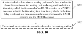
- FIG. 10 Another alternative processing flow of a method for channel transmission according to the embodiment of the present disclosure, as illustrated in FIG. 10 , includes the following operations.
- the network device determines a starting position for channel transmission, the starting position being positioned after a time delay which is after an end of an RACH occasion or a PUSCH occasion; herein the time delay is at least two symbols, or the time delay is relevant to a time-domain relationship between the RACH occasion and the PUSCH occasion.
- the description of the network device determining the starting position of the time window for channel detection is the same as the description of the terminal device autonomously determining the starting position of the time window for channel detection according to the message transmitted by the network device in S501 of the above embodiment, and details are not described herein.
- the method further includes:
- the network device starts to transmit a channel based on the time window.
- the channel may be transmitted at the starting position of the time window, or may not be transmitted at the starting position of the time window.
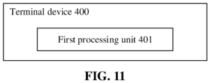
- an embodiment of the present disclosure further provides a terminal device.
- a schematic structural diagram of the terminal device, as illustrated in FIG. 11 the terminal device 400 includes: a first processing unit 401, configured to determine a starting position of a time window for channel detection based on a message transmitted by a network device, the starting position being positioned after a time delay which is after an end of an RACH occasion or a PUSCH occasion; herein the time delay is at least two symbols, or the time delay is relevant to a time-domain relationship between the RACH occasion and the PUSCH occasion.
- the time delay is a fixed value.
- the time delay is determined according to at least one of a processing time of the network device for PUSCH or a preparation time of the network device for PDSCH.
- the time delay is a variable value.
- the time delay is determined according to a subcarrier spacing of PDCCH or a subcarrier spacing of PUSCH.
- the time-domain relationship between the RACH occasion and the PUSCH occasion is determined by the terminal device according to the message transmitted by the network device, or the time-domain relationship between the RACH occasion and the PUSCH occasion is preset.
- the time-domain relationship between the RACH occasion and the PUSCH occasion includes at least one of: a time sequential relationship between the RACH occasion and the PUSCH occasion; or a time difference between the RACH occasion and the PUSCH occasion.
- the time delay is a sum of a fixed delay and the time difference between the RACH occasion and the PUSCH occasion.
- the fixed delay is at least one symbol.
- the first processing unit 401 is further configured to start to detect a channel at the starting position.
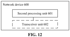
- an embodiment of the present disclosure further provides a network device.
- the network device 600 includes: a second processing unit 601, configured to determine a starting position of a time window for channel transmission, the starting position being positioned after a time delay which is after an end of an RACH occasion or a PUSCH occasion; herein the time delay is at least two symbols, or the time delay is relevant to a time-domain relationship between the RACH occasion and the PUSCH occasion.
- the time delay is a fixed value.
- the time delay is determined according to at least one of a processing time of the network device for PUSCH and a preparation time of the network device for PDSCH.
- the time delay is a variable value.
- the time delay is determined according to a subcarrier spacing of Typel-PDCCH or a subcarrier spacing of PUSCH.
- the time-domain relationship between the RACH occasion and the PUSCH occasion is determined by the terminal device according to the message transmitted by the network device, or the time-domain relationship between the RACH occasion and the PUSCH occasion is preset.
- the time-domain relationship between the RACH occasion and the PUSCH occasion includes at least one of: a time sequential relationship between the RACH occasion and the PUSCH occasion; or a time difference between the RACH occasion and the PUSCH occasion.
- the time delay is a sum of a fixed delay and the time difference between the RACH occasion and the PUSCH occasion.
- the fixed delay is at least one symbol.
- the network device 600 further includes a transceiver unit 602, which is configured to start to transmit a channel based on the time window.
- the channel may be transmitted at the starting position of the time window, or may not be transmitted at the starting position of the time window.
- An embodiment of the present disclosure further provides a terminal device which includes a processor and a memory for storing a computer program executable by the processor.
- the processor is configured to run the computer program to execute steps of the method for channel transmission executed by the terminal device.
- An embodiment of the present disclosure further provides a network device which includes a processor and a memory for storing a computer program executable by the processor.
- the processor is configured to run the computer program to execute steps of the method for channel transmission executed by the terminal device.
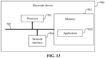
- FIG. 13 is a schematic diagram of a hardware structure of an electronic device (terminal device and network device) according to an embodiment of the present disclosure.
- the electronic device 700 includes at least one processor 701, a memory 702, and at least one network interface 704.
- the various components in the terminal device 700 are coupled together through a bus system 705.
- the bus system 705 is configured to implement connection communication among these components.
- the bus system 705 includes a data bus and further includes a power bus, a control bus and a state signal bus. However, for clear illustration, various buses are marked as the bus system 705 in FIG. 13 .
- the memory 702 may be a volatile memory or a non-volatile memory, or may include both the volatile and non-volatile memories.
- the non-volatile memory may be a Read-Only Memory (ROM), a Programmable Read-Only Memory (PROM), an Erasable Programmable Read-Only Memory (EPROM), an Electrically Erasable Programmable Read-Only Memory (EEPROM), a Ferromagnetic Random Access Memory (FRAM), a flash memory, a magnetic surface memory, an optical disk, or a read-only Compact Disc Read-Only Memory (CD-ROM).
- the magnetic surface memory may be a magnetic disk memory or a magnetic tape memory.
- the volatile memory may be a Random Access Memory (RAM), which functions as an external cache.
- RAM Random Access Memory
- SRAM Static Random Access Memory
- SSRAM Synchronous Static Random Access Memory
- DRAM Dynamic Random Access Memory
- SDRAM Synchronous Dynamic Random Access Memory
- DDRSDRAM Double Data Rate Synchronous Dynamic Random Access Memory
- ESDRAM Enhanced Synchronous Dynamic Random Access Memory
- SLDRAM SyncLink Dynamic Random Access Memory
- DRRAM Direct Rambus Random Access Memory
- the memory 702 in the embodiments of the present disclosure is used to store various types of data to support the operation of the electronic device 700.
- Examples of such data include any computer program for operation on electronic device 700, such as an application program 7022.
- a program for implementing the method of the embodiments of the present disclosure may be included in the application program 7022.
- the method disclosed in the above embodiments of the present disclosure may be applied to or implemented by the processor 701.
- the processor 701 may be an integrated circuit chip having a signal processing capability. In an implementation, the operations of the above method may be performed by integrated logic circuits of hardware in the processor 701 or by instructions in the form of software.
- the processor 701 may be a general purpose processor, a Digital Signal Processor (DSP), or other programmable logic devices, a discrete gate or a transistor logic device, a discrete hardware component, or the like.
- DSP Digital Signal Processor
- the processor 701 may implement or perform the methods, operations, and logical block diagrams disclosed in the embodiments of the present disclosure.
- the general purpose processor may be a microprocessor or any conventional processor or the like.
- the operations of the method disclosed in connection with the embodiments of the present disclosure may be directly performed by a hardware decoding processor or performed by a combination of hardware and software modules in the decoding processor.
- the software module may be located in a storage medium located in the memory 702, and the processor 701 reads the information in the memory 702 to perform the operations of the foregoing method in conjunction with hardware thereof.
- the electronic device 700 may be implemented by one or more Application Specific Integrated Circuits (ASICs), DSPs, Programmable Logic Devices (PLDs), Complex Programmable Logic Devices (CPLDs), FPGAs, general purpose processors, controllers, MCUs, MPUs, or other electronic components for performing the foregoing methods.
- ASICs Application Specific Integrated Circuits
- DSPs Digital Signal processors
- PLDs Programmable Logic Devices
- CPLDs Complex Programmable Logic Devices
- FPGAs general purpose processors
- controllers MCUs, MPUs, or other electronic components for performing the foregoing methods.
- An embodiment, not claimed, of the present disclosure further provides a storage medium for storing a computer program.
- the storage medium may be applied to the terminal device in the embodiments of the present disclosure, and the computer program causes the computer to execute the flows of the respective methods in the embodiments of the present disclosure.
- the computer program causes the computer to execute the flows of the respective methods in the embodiments of the present disclosure.
- the storage medium may be applied to the network devices in the embodiments of the present disclosure, and the computer program causes the computer to execute the flows of the respective methods in the embodiments of the present disclosure.
- the computer program causes the computer to execute the flows of the respective methods in the embodiments of the present disclosure.
- each flow and/or block in the flow diagrams and/or block diagrams, and combinations of flow and/or block in the flow diagrams and/or block diagrams may be implemented by computer program instructions.
- These computer program instructions may be provided to a processor of a general purpose computer, a special purpose computer, an embedded processor, or other programmable data processing device to produce a machine such that the instructions executed by the processor of the computer or other programmable data processing device produce means for implementing the functions specified in one process or multiple processes in the flowcharts and/or one block or multiple blocks in the block diagrams.
- These computer program instructions may also be stored in a computer-readable memory capable of directing a computer or other programmable data processing device to operate in a particular manner, such that the instructions stored in the computer-readable memory produce an article of manufacture including instruction means that perform the functions specified in one process or multiple processes in the flowcharts and/or one block or multiple blocks in the block diagrams.
- These computer program instructions may also be loaded onto a computer or other programmable data processing device such that a series of operational operations are performed on the computer or other programmable device to produce a computer-implemented process, such that the instructions that execute on the computer or other programmable device provide operations for implementing the functions specified in one process or multiple processes in the flowcharts and/or one block or multiple blocks in the block diagrams.
Landscapes
- Engineering & Computer Science (AREA)
- Signal Processing (AREA)
- Computer Networks & Wireless Communication (AREA)
- Physics & Mathematics (AREA)
- Mathematical Physics (AREA)
- Mobile Radio Communication Systems (AREA)
Claims (11)
- Verfahren zur Kanaldetektion, das auf einen 2-stufigen wahlfreien Zugriff anwendbar ist, wobei das Verfahren Folgendes umfasst:Bestimmen (S301) durch eine Endgerätvorrichtung einer Startposition eines Zeitfensters zur Kanaldetektion auf der Grundlage einer Nachricht, die durch eine Netzvorrichtung gesendet wird, wobei die Startposition nach einer Zeitverzögerung positioniert ist, die nach einem Ende eines Ereignisses eines Kanals mit wahlfreiem Zugriff, RACH-Ereignis, liegt; wobeidie Zeitverzögerung für eine Zeitdomänenbeziehung zwischen dem RACH-Ereignis und einem Ereignis eines gemeinsam verwendeten physischen Aufwärtsstreckenkanals, PUSCH-Ereignis, relevant ist; wobei dann, wenn die Zeitdomänenbeziehung zwischen dem RACH-Ereignis und dem PUSCH-Ereignis ist, dass das PUSCH-Ereignis nach dem RACH-Ereignis liegt, die Zeitverzögerung nicht weniger als eine Summe einer festen Verzögerung und der Zeitdifferenz zwischen dem RACH-Ereignis und dem PUSCH-Ereignis ist;die Startposition eine Startposition eines ersten Symbols eines ersten Steuerungsbetriebsmittelsatzes, CORESET, nach der Zeitverzögerung, die nach dem Ende des RACH-Ereignisses liegt, ist; unddas CORESET ein CORESET ist, das für einen gemeinsamen Suchraum eines physischen Type1-Abwärtsstreckensteuerkanals, gemeinsame Typel-PDCCH-Suchraum, konfiguriert ist, und der gemeinsame Type1-PDCCH-Suchraum, das RACH-Ereignis und das PUSCH-Ereignis durch die Endgerätvorrichtung gemäß der Nachricht, die durch die Netzvorrichtung gesendet wird, bestimmt werden.
- Verfahren nach Anspruch 1, wobei die Zeitdomänenbeziehung zwischen dem RACH-Ereignis und dem PUSCH-Ereignis durch die Endgerätvorrichtung gemäß der Nachricht, die durch die Netzvorrichtung gesendet wird, bestimmt wird oder die Zeitdomänenbeziehung zwischen dem RACH-Ereignis und dem PUSCH-Ereignis voreingestellt ist.
- Verfahren nach Anspruch 1 oder 2, wobei die feste Verzögerung ein Symbol ist.
- Verfahren nach einem der Ansprüche 1 bis 3, die ferner Folgendes umfasst:
Beginnen der Detektion (S302) eines Kanals durch die Endgerätvorrichtung an der Startposition. - Verfahren nach einem der Ansprüche 1 bis 4, wobei der Kanal einen PDCCH umfasst.
- Verfahren nach einem der Ansprüche 1 bis 5, wobei die Nachricht eine Funkbetriebsmittelsteuerungsnachricht, RRC-Nachricht, oder eine Systemnachricht ist.
- Verfahren zur Kanalübertragung, das auf einen 2-stufigen wahlfreien Zugriff anwendbar ist, wobei das Verfahren Folgendes umfasst:Bestimmen (S501) durch eine Netzvorrichtung einer Startposition eines Zeitfensters zur Kanalübertragung, wobei die Startposition nach einer Zeitverzögerung positioniert ist, die nach einem Ende eines Ereignisses eines Kanals mit wahlfreiem Zugriff, RACH-Ereignis, liegt; wobeidie Zeitverzögerung für eine Zeitdomänenbeziehung zwischen dem RACH-Ereignis und einem Ereignis eines gemeinsam verwendeten physischen Aufwärtsstreckenkanals, PUSCH-Ereignis, relevant ist; wobei dann, wenn die Zeitdomänenbeziehung zwischen dem RACH-Ereignis und dem PUSCH-Ereignis ist, dass das PUSCH-Ereignis nach dem RACH-Ereignis liegt, die Zeitverzögerung nicht weniger als eine Summe einer festen Verzögerung und der Zeitdifferenz zwischen dem RACH-Ereignis und dem PUSCH-Ereignis ist; unddie Startposition eine Startposition eines ersten Symbols eines ersten Steuerungsbetriebsmittelsatzes, CORESET, nach der Zeitverzögerung, die nach dem Ende des RACH-Ereignisses liegt, ist; wobei das Verfahren ferner Folgendes umfasst:
Bestimmen durch die Netzvorrichtung eines gemeinsamen Suchraums eines physischen Type1-Abwärtsstreckensteuerkanals, gemeinsamer Typel-PDCCH-Suchraum, des RACH-Ereignisses und des PUSCH-Ereignises, wobei das CORESET ein CORESET ist, das für den gemeinsamen Type1-PDCCH-Suchraum konfiguriert ist. - Verfahren nach Anspruch 7, wobei die Zeitdomänenbeziehung zwischen dem RACH-Ereignis und dem PUSCH-Ereignis voreingestellt ist.
- Verfahren nach Anspruch 7 oder 8, wobei die feste Verzögerung ein Symbol ist.
- Endgerätvorrichtung, die einen Prozessor und einen Speicher zum Speichern eines Computerprogramms, das durch den Prozessor ausführbar ist, umfasst, wobei der Prozessor konfiguriert ist, das Computerprogramm zu betreiben, um Schritte des Verfahrens nach einem der Ansprüche 1 bis 6 auszuführen.
- Netzvorrichtung, die einen Prozessor und einen Speicher zum Speichern eines Computerprogramms, das durch den Prozessor ausführbar ist, umfasst, wobei der Prozessor konfiguriert ist, das Computerprogramm zu betreiben, um Schritte des Verfahrens nach einem der Ansprüche 7 bis 9 auszuführen.
Applications Claiming Priority (1)
| Application Number | Priority Date | Filing Date | Title |
|---|---|---|---|
| PCT/CN2019/080234 WO2020191760A1 (zh) | 2019-03-28 | 2019-03-28 | 一种信道传输方法、电子设备及存储介质 |
Publications (3)
| Publication Number | Publication Date |
|---|---|
| EP3937586A1 EP3937586A1 (de) | 2022-01-12 |
| EP3937586A4 EP3937586A4 (de) | 2022-03-23 |
| EP3937586B1 true EP3937586B1 (de) | 2023-05-10 |
Family
ID=72610903
Family Applications (1)
| Application Number | Title | Priority Date | Filing Date |
|---|---|---|---|
| EP19921405.7A Active EP3937586B1 (de) | 2019-03-28 | 2019-03-28 | Kanaldetektierungsverfahren, kanalübertragungsverfahren, endgerät und netzgerät |
Country Status (8)
| Country | Link |
|---|---|
| US (1) | US12507283B2 (de) |
| EP (1) | EP3937586B1 (de) |
| JP (1) | JP7262610B2 (de) |
| KR (1) | KR102842147B1 (de) |
| CN (2) | CN114173424B (de) |
| BR (1) | BR112021019005A2 (de) |
| MX (1) | MX2021011800A (de) |
| WO (1) | WO2020191760A1 (de) |
Families Citing this family (5)
| Publication number | Priority date | Publication date | Assignee | Title |
|---|---|---|---|---|
| EP3937586B1 (de) * | 2019-03-28 | 2023-05-10 | Guangdong Oppo Mobile Telecommunications Corp., Ltd. | Kanaldetektierungsverfahren, kanalübertragungsverfahren, endgerät und netzgerät |
| CN111757482B (zh) * | 2019-03-29 | 2022-12-16 | 大唐移动通信设备有限公司 | 一种搜索空间时域位置确定方法、装置及通信设备 |
| US12526849B2 (en) * | 2020-06-10 | 2026-01-13 | Lenovo (Singapore) Pte. Limited | Method and apparatus for more power efficient physical downlink control channel monitoring after a random access transmission |
| US20240155695A1 (en) * | 2021-03-18 | 2024-05-09 | Telefonaktiebolaget Lm Ericsson (Publ) | Random Access in a Wireless Communication Network |
| CN120111705A (zh) * | 2023-12-05 | 2025-06-06 | 维沃移动通信有限公司 | Rar接收窗口的处理方法、终端及网络侧设备 |
Family Cites Families (24)
| Publication number | Priority date | Publication date | Assignee | Title |
|---|---|---|---|---|
| US8111656B2 (en) * | 2008-05-02 | 2012-02-07 | Nokia Corporation | Method and apparatus for providing random access window configuration |
| KR102909813B1 (ko) * | 2016-04-04 | 2026-01-09 | 삼성전자 주식회사 | 무선 통신 시스템에서 피드백 송수신 방법 및 장치 |
| EP3520538A1 (de) * | 2016-09-28 | 2019-08-07 | Sony Corporation | Direktzugriff in drahtlosen systemen der nächsten generation |
| CN107889244B (zh) * | 2016-09-30 | 2020-06-02 | 华为技术有限公司 | 通信方法、装置及计算机可读存储介质 |
| SG11201907066VA (en) * | 2017-02-03 | 2019-08-27 | Ntt Docomo Inc | User apparatus, and preamble transmission method |
| CN109152027B (zh) * | 2017-06-16 | 2023-09-29 | 华为技术有限公司 | 通信方法及装置 |
| KR102406365B1 (ko) * | 2017-07-28 | 2022-06-08 | 삼성전자주식회사 | 단말 및 기지국 간의 rach 절차 수행 방법 및 이를 위한 기지국 및 단말 |
| US10785739B2 (en) * | 2017-08-10 | 2020-09-22 | Ofinno, Llc | Beam indication in RACH |
| US10555338B2 (en) * | 2017-08-11 | 2020-02-04 | Mediatek Inc. | NR-PRACH multiple Msg1 transmission |
| CN109413754B (zh) * | 2017-08-18 | 2021-01-29 | 维沃移动通信有限公司 | 一种信息接收、发送方法、终端及基站 |
| CN109729589B (zh) * | 2017-10-31 | 2021-08-31 | 华为技术有限公司 | 上行信号传输方法、终端、网络设备及系统 |
| CN110300423B (zh) * | 2018-03-22 | 2022-12-20 | 华硕电脑股份有限公司 | 无线通信系统中用于波束故障处置的方法和设备 |
| US10880895B2 (en) * | 2018-05-27 | 2020-12-29 | Brian Gordaychik | Variable length downlink control information formats for next generation radio technologies |
| CN112740572B (zh) * | 2018-07-20 | 2024-05-17 | 株式会社Ntt都科摩 | 用户终端以及基站 |
| CN112567827B (zh) * | 2018-08-10 | 2023-04-28 | 韦勒斯标准与技术协会公司 | 无线通信系统中发送和接收物理信道和信号的方法以及使用其的装置 |
| US11259293B2 (en) * | 2019-01-10 | 2022-02-22 | Ofinno, Llc | Two-stage preamble transmission |
| US11032854B2 (en) * | 2019-01-18 | 2021-06-08 | Qualcomm Incorporated | Variable payload size for two-step random access |
| CN118473482A (zh) * | 2019-02-13 | 2024-08-09 | 交互数字专利控股公司 | 用于波束失败恢复的方法和无线发射接收单元 |
| CN113303020B (zh) * | 2019-02-13 | 2025-03-25 | 三星电子株式会社 | 无线通信系统中的处理两步随机接入过程中的msg a重传的方法和设备 |
| WO2020167058A1 (ko) * | 2019-02-15 | 2020-08-20 | 엘지전자 주식회사 | 무선 통신 시스템에서 신호를 송수신 하는 방법 및 이를 지원하는 장치 |
| WO2020167048A1 (ko) * | 2019-02-15 | 2020-08-20 | 엘지전자 주식회사 | 무선 통신 시스템에서 신호를 송수신 하는 방법 및 이를 지원하는 장치 |
| US12200776B2 (en) * | 2019-03-19 | 2025-01-14 | Lg Electronics Inc. | Method for transmitting and receiving signal in wireless communication system and device supporting same |
| JP7297921B2 (ja) * | 2019-03-27 | 2023-06-26 | アップル インコーポレイテッド | 無認可動作を伴う新無線(nr)のための2ステップrach |
| EP3937586B1 (de) * | 2019-03-28 | 2023-05-10 | Guangdong Oppo Mobile Telecommunications Corp., Ltd. | Kanaldetektierungsverfahren, kanalübertragungsverfahren, endgerät und netzgerät |
-
2019
- 2019-03-28 EP EP19921405.7A patent/EP3937586B1/de active Active
- 2019-03-28 WO PCT/CN2019/080234 patent/WO2020191760A1/zh not_active Ceased
- 2019-03-28 KR KR1020217034750A patent/KR102842147B1/ko active Active
- 2019-03-28 CN CN202111615617.0A patent/CN114173424B/zh active Active
- 2019-03-28 CN CN201980093939.8A patent/CN113557785A/zh active Pending
- 2019-03-28 JP JP2021557423A patent/JP7262610B2/ja active Active
- 2019-03-28 BR BR112021019005A patent/BR112021019005A2/pt unknown
- 2019-03-28 MX MX2021011800A patent/MX2021011800A/es unknown
-
2021
- 2021-09-28 US US17/487,320 patent/US12507283B2/en active Active
Non-Patent Citations (1)
| Title |
|---|
| 3GPP: "3rd Generation Partnership Project; Technical Specification Group Radio Access Network; NR; Physical layer procedures for control (Release 15)", 3GPP TS 38.213 V15.5.0, 27 March 2019 (2019-03-27), XP055770682, Retrieved from the Internet <URL:http://www.3gpp.org> [retrieved on 20210201] * |
Also Published As
| Publication number | Publication date |
|---|---|
| EP3937586A1 (de) | 2022-01-12 |
| KR102842147B1 (ko) | 2025-08-01 |
| CN114173424B (zh) | 2023-09-12 |
| MX2021011800A (es) | 2021-10-26 |
| CN113557785A (zh) | 2021-10-26 |
| US12507283B2 (en) | 2025-12-23 |
| WO2020191760A1 (zh) | 2020-10-01 |
| CN114173424A (zh) | 2022-03-11 |
| EP3937586A4 (de) | 2022-03-23 |
| US20220015153A1 (en) | 2022-01-13 |
| BR112021019005A2 (pt) | 2021-11-30 |
| JP7262610B2 (ja) | 2023-04-21 |
| KR20210146974A (ko) | 2021-12-06 |
| JP2022531831A (ja) | 2022-07-12 |
Similar Documents
| Publication | Publication Date | Title |
|---|---|---|
| US12507283B2 (en) | Channel transmission method, electronic device, and storage medium | |
| US20220022269A1 (en) | Random access channel method, device and storage medium | |
| WO2020034224A1 (zh) | 一种窗口调整方法及装置、网络设备、终端 | |
| WO2020186466A1 (zh) | 无线通信的方法、终端设备和网络设备 | |
| CN113678562B (zh) | 通信方法、终端设备和网络设备 | |
| EP4266769A1 (de) | Direktzugriffsverfahren sowie elektronische vorrichtung und speichermedium | |
| CN113966586A (zh) | 数据传输方法、终端设备及存储介质 | |
| CN112970319A (zh) | 一种消息重传方法、设备及存储介质 | |
| CN113678560A (zh) | 随机接入过程中传输信息的方法、终端设备和网络设备 | |
| JP7496834B2 (ja) | 2ステップのランダムアクセスのための方法、端末デバイス及びネットワークデバイス | |
| CN114223308B (zh) | 一种随机接入方法、电子设备及存储介质 | |
| EP3993546A1 (de) | Verfahren und vorrichtung mit wahlfreiem zugriff und endgerät | |
| EP3869900A1 (de) | Direktzugriffsverfahren, endgerätevorrichtung und netzwerkvorrichtung | |
| CN112806068A (zh) | 一种资源管理方法、设备及存储介质 | |
| JP2021528009A (ja) | チャネルアクセスタイプ指示方法、端末装置及びネットワーク装置 | |
| JP7542064B2 (ja) | ランダムアクセス問題の報告方法、端末デバイス及び記憶媒体 | |
| CN112806087B (zh) | 一种随机接入方法、电子设备及存储介质 | |
| WO2020220252A1 (zh) | 一种随机接入方法、设备及存储介质 | |
| CN112771967A (zh) | 一种传输参数确定方法及装置、用户设备 | |
| CN113711682A (zh) | 一种随机接入方法及装置、用户设备、网络设备 |
Legal Events
| Date | Code | Title | Description |
|---|---|---|---|
| STAA | Information on the status of an ep patent application or granted ep patent |
Free format text: STATUS: THE INTERNATIONAL PUBLICATION HAS BEEN MADE |
|
| PUAI | Public reference made under article 153(3) epc to a published international application that has entered the european phase |
Free format text: ORIGINAL CODE: 0009012 |
|
| STAA | Information on the status of an ep patent application or granted ep patent |
Free format text: STATUS: REQUEST FOR EXAMINATION WAS MADE |
|
| 17P | Request for examination filed |
Effective date: 20211004 |
|
| AK | Designated contracting states |
Kind code of ref document: A1 Designated state(s): AL AT BE BG CH CY CZ DE DK EE ES FI FR GB GR HR HU IE IS IT LI LT LU LV MC MK MT NL NO PL PT RO RS SE SI SK SM TR |
|
| A4 | Supplementary search report drawn up and despatched |
Effective date: 20220218 |
|
| RIC1 | Information provided on ipc code assigned before grant |
Ipc: H04W 74/08 20090101AFI20220215BHEP |
|
| DAV | Request for validation of the european patent (deleted) | ||
| DAX | Request for extension of the european patent (deleted) | ||
| GRAP | Despatch of communication of intention to grant a patent |
Free format text: ORIGINAL CODE: EPIDOSNIGR1 |
|
| STAA | Information on the status of an ep patent application or granted ep patent |
Free format text: STATUS: GRANT OF PATENT IS INTENDED |
|
| INTG | Intention to grant announced |
Effective date: 20221125 |
|
| GRAS | Grant fee paid |
Free format text: ORIGINAL CODE: EPIDOSNIGR3 |
|
| GRAA | (expected) grant |
Free format text: ORIGINAL CODE: 0009210 |
|
| STAA | Information on the status of an ep patent application or granted ep patent |
Free format text: STATUS: THE PATENT HAS BEEN GRANTED |
|
| AK | Designated contracting states |
Kind code of ref document: B1 Designated state(s): AL AT BE BG CH CY CZ DE DK EE ES FI FR GB GR HR HU IE IS IT LI LT LU LV MC MK MT NL NO PL PT RO RS SE SI SK SM TR |
|
| REG | Reference to a national code |
Ref country code: GB Ref legal event code: FG4D |
|
| REG | Reference to a national code |
Ref country code: AT Ref legal event code: REF Ref document number: 1568019 Country of ref document: AT Kind code of ref document: T Effective date: 20230515 Ref country code: CH Ref legal event code: EP |
|
| REG | Reference to a national code |
Ref country code: DE Ref legal event code: R096 Ref document number: 602019028964 Country of ref document: DE |
|
| REG | Reference to a national code |
Ref country code: IE Ref legal event code: FG4D |
|
| P01 | Opt-out of the competence of the unified patent court (upc) registered |
Effective date: 20230525 |
|
| REG | Reference to a national code |
Ref country code: LT Ref legal event code: MG9D |
|
| REG | Reference to a national code |
Ref country code: NL Ref legal event code: MP Effective date: 20230510 |
|
| REG | Reference to a national code |
Ref country code: AT Ref legal event code: MK05 Ref document number: 1568019 Country of ref document: AT Kind code of ref document: T Effective date: 20230510 |
|
| PG25 | Lapsed in a contracting state [announced via postgrant information from national office to epo] |
Ref country code: SE Free format text: LAPSE BECAUSE OF FAILURE TO SUBMIT A TRANSLATION OF THE DESCRIPTION OR TO PAY THE FEE WITHIN THE PRESCRIBED TIME-LIMIT Effective date: 20230510 Ref country code: PT Free format text: LAPSE BECAUSE OF FAILURE TO SUBMIT A TRANSLATION OF THE DESCRIPTION OR TO PAY THE FEE WITHIN THE PRESCRIBED TIME-LIMIT Effective date: 20230911 Ref country code: NO Free format text: LAPSE BECAUSE OF FAILURE TO SUBMIT A TRANSLATION OF THE DESCRIPTION OR TO PAY THE FEE WITHIN THE PRESCRIBED TIME-LIMIT Effective date: 20230810 Ref country code: NL Free format text: LAPSE BECAUSE OF FAILURE TO SUBMIT A TRANSLATION OF THE DESCRIPTION OR TO PAY THE FEE WITHIN THE PRESCRIBED TIME-LIMIT Effective date: 20230510 Ref country code: ES Free format text: LAPSE BECAUSE OF FAILURE TO SUBMIT A TRANSLATION OF THE DESCRIPTION OR TO PAY THE FEE WITHIN THE PRESCRIBED TIME-LIMIT Effective date: 20230510 Ref country code: AT Free format text: LAPSE BECAUSE OF FAILURE TO SUBMIT A TRANSLATION OF THE DESCRIPTION OR TO PAY THE FEE WITHIN THE PRESCRIBED TIME-LIMIT Effective date: 20230510 |
|
| PG25 | Lapsed in a contracting state [announced via postgrant information from national office to epo] |
Ref country code: RS Free format text: LAPSE BECAUSE OF FAILURE TO SUBMIT A TRANSLATION OF THE DESCRIPTION OR TO PAY THE FEE WITHIN THE PRESCRIBED TIME-LIMIT Effective date: 20230510 Ref country code: PL Free format text: LAPSE BECAUSE OF FAILURE TO SUBMIT A TRANSLATION OF THE DESCRIPTION OR TO PAY THE FEE WITHIN THE PRESCRIBED TIME-LIMIT Effective date: 20230510 Ref country code: LV Free format text: LAPSE BECAUSE OF FAILURE TO SUBMIT A TRANSLATION OF THE DESCRIPTION OR TO PAY THE FEE WITHIN THE PRESCRIBED TIME-LIMIT Effective date: 20230510 Ref country code: LT Free format text: LAPSE BECAUSE OF FAILURE TO SUBMIT A TRANSLATION OF THE DESCRIPTION OR TO PAY THE FEE WITHIN THE PRESCRIBED TIME-LIMIT Effective date: 20230510 Ref country code: IS Free format text: LAPSE BECAUSE OF FAILURE TO SUBMIT A TRANSLATION OF THE DESCRIPTION OR TO PAY THE FEE WITHIN THE PRESCRIBED TIME-LIMIT Effective date: 20230910 Ref country code: HR Free format text: LAPSE BECAUSE OF FAILURE TO SUBMIT A TRANSLATION OF THE DESCRIPTION OR TO PAY THE FEE WITHIN THE PRESCRIBED TIME-LIMIT Effective date: 20230510 Ref country code: GR Free format text: LAPSE BECAUSE OF FAILURE TO SUBMIT A TRANSLATION OF THE DESCRIPTION OR TO PAY THE FEE WITHIN THE PRESCRIBED TIME-LIMIT Effective date: 20230811 |
|
| PG25 | Lapsed in a contracting state [announced via postgrant information from national office to epo] |
Ref country code: FI Free format text: LAPSE BECAUSE OF FAILURE TO SUBMIT A TRANSLATION OF THE DESCRIPTION OR TO PAY THE FEE WITHIN THE PRESCRIBED TIME-LIMIT Effective date: 20230510 |
|
| PG25 | Lapsed in a contracting state [announced via postgrant information from national office to epo] |
Ref country code: SK Free format text: LAPSE BECAUSE OF FAILURE TO SUBMIT A TRANSLATION OF THE DESCRIPTION OR TO PAY THE FEE WITHIN THE PRESCRIBED TIME-LIMIT Effective date: 20230510 |
|
| PG25 | Lapsed in a contracting state [announced via postgrant information from national office to epo] |
Ref country code: SM Free format text: LAPSE BECAUSE OF FAILURE TO SUBMIT A TRANSLATION OF THE DESCRIPTION OR TO PAY THE FEE WITHIN THE PRESCRIBED TIME-LIMIT Effective date: 20230510 Ref country code: SK Free format text: LAPSE BECAUSE OF FAILURE TO SUBMIT A TRANSLATION OF THE DESCRIPTION OR TO PAY THE FEE WITHIN THE PRESCRIBED TIME-LIMIT Effective date: 20230510 Ref country code: RO Free format text: LAPSE BECAUSE OF FAILURE TO SUBMIT A TRANSLATION OF THE DESCRIPTION OR TO PAY THE FEE WITHIN THE PRESCRIBED TIME-LIMIT Effective date: 20230510 Ref country code: EE Free format text: LAPSE BECAUSE OF FAILURE TO SUBMIT A TRANSLATION OF THE DESCRIPTION OR TO PAY THE FEE WITHIN THE PRESCRIBED TIME-LIMIT Effective date: 20230510 Ref country code: DK Free format text: LAPSE BECAUSE OF FAILURE TO SUBMIT A TRANSLATION OF THE DESCRIPTION OR TO PAY THE FEE WITHIN THE PRESCRIBED TIME-LIMIT Effective date: 20230510 Ref country code: CZ Free format text: LAPSE BECAUSE OF FAILURE TO SUBMIT A TRANSLATION OF THE DESCRIPTION OR TO PAY THE FEE WITHIN THE PRESCRIBED TIME-LIMIT Effective date: 20230510 |
|
| REG | Reference to a national code |
Ref country code: DE Ref legal event code: R097 Ref document number: 602019028964 Country of ref document: DE |
|
| PLBE | No opposition filed within time limit |
Free format text: ORIGINAL CODE: 0009261 |
|
| STAA | Information on the status of an ep patent application or granted ep patent |
Free format text: STATUS: NO OPPOSITION FILED WITHIN TIME LIMIT |
|
| 26N | No opposition filed |
Effective date: 20240213 |
|
| PG25 | Lapsed in a contracting state [announced via postgrant information from national office to epo] |
Ref country code: SI Free format text: LAPSE BECAUSE OF FAILURE TO SUBMIT A TRANSLATION OF THE DESCRIPTION OR TO PAY THE FEE WITHIN THE PRESCRIBED TIME-LIMIT Effective date: 20230510 |
|
| PG25 | Lapsed in a contracting state [announced via postgrant information from national office to epo] |
Ref country code: SI Free format text: LAPSE BECAUSE OF FAILURE TO SUBMIT A TRANSLATION OF THE DESCRIPTION OR TO PAY THE FEE WITHIN THE PRESCRIBED TIME-LIMIT Effective date: 20230510 Ref country code: IT Free format text: LAPSE BECAUSE OF FAILURE TO SUBMIT A TRANSLATION OF THE DESCRIPTION OR TO PAY THE FEE WITHIN THE PRESCRIBED TIME-LIMIT Effective date: 20230510 |
|
| REG | Reference to a national code |
Ref country code: CH Ref legal event code: PL |
|
| PG25 | Lapsed in a contracting state [announced via postgrant information from national office to epo] |
Ref country code: BG Free format text: LAPSE BECAUSE OF FAILURE TO SUBMIT A TRANSLATION OF THE DESCRIPTION OR TO PAY THE FEE WITHIN THE PRESCRIBED TIME-LIMIT Effective date: 20230510 |
|
| PG25 | Lapsed in a contracting state [announced via postgrant information from national office to epo] |
Ref country code: LU Free format text: LAPSE BECAUSE OF NON-PAYMENT OF DUE FEES Effective date: 20240328 |
|
| PG25 | Lapsed in a contracting state [announced via postgrant information from national office to epo] |
Ref country code: MC Free format text: LAPSE BECAUSE OF FAILURE TO SUBMIT A TRANSLATION OF THE DESCRIPTION OR TO PAY THE FEE WITHIN THE PRESCRIBED TIME-LIMIT Effective date: 20230510 |
|
| PG25 | Lapsed in a contracting state [announced via postgrant information from national office to epo] |
Ref country code: MC Free format text: LAPSE BECAUSE OF FAILURE TO SUBMIT A TRANSLATION OF THE DESCRIPTION OR TO PAY THE FEE WITHIN THE PRESCRIBED TIME-LIMIT Effective date: 20230510 Ref country code: LU Free format text: LAPSE BECAUSE OF NON-PAYMENT OF DUE FEES Effective date: 20240328 Ref country code: BG Free format text: LAPSE BECAUSE OF FAILURE TO SUBMIT A TRANSLATION OF THE DESCRIPTION OR TO PAY THE FEE WITHIN THE PRESCRIBED TIME-LIMIT Effective date: 20230510 |
|
| REG | Reference to a national code |
Ref country code: BE Ref legal event code: MM Effective date: 20240331 |
|
| PG25 | Lapsed in a contracting state [announced via postgrant information from national office to epo] |
Ref country code: BE Free format text: LAPSE BECAUSE OF NON-PAYMENT OF DUE FEES Effective date: 20240331 |
|
| PG25 | Lapsed in a contracting state [announced via postgrant information from national office to epo] |
Ref country code: IE Free format text: LAPSE BECAUSE OF NON-PAYMENT OF DUE FEES Effective date: 20240328 |
|
| PG25 | Lapsed in a contracting state [announced via postgrant information from national office to epo] |
Ref country code: IE Free format text: LAPSE BECAUSE OF NON-PAYMENT OF DUE FEES Effective date: 20240328 Ref country code: BE Free format text: LAPSE BECAUSE OF NON-PAYMENT OF DUE FEES Effective date: 20240331 Ref country code: CH Free format text: LAPSE BECAUSE OF NON-PAYMENT OF DUE FEES Effective date: 20240331 |
|
| PG25 | Lapsed in a contracting state [announced via postgrant information from national office to epo] |
Ref country code: CY Free format text: LAPSE BECAUSE OF FAILURE TO SUBMIT A TRANSLATION OF THE DESCRIPTION OR TO PAY THE FEE WITHIN THE PRESCRIBED TIME-LIMIT; INVALID AB INITIO Effective date: 20190328 |
|
| PG25 | Lapsed in a contracting state [announced via postgrant information from national office to epo] |
Ref country code: HU Free format text: LAPSE BECAUSE OF FAILURE TO SUBMIT A TRANSLATION OF THE DESCRIPTION OR TO PAY THE FEE WITHIN THE PRESCRIBED TIME-LIMIT; INVALID AB INITIO Effective date: 20190328 |
|
| PG25 | Lapsed in a contracting state [announced via postgrant information from national office to epo] |
Ref country code: TR Free format text: LAPSE BECAUSE OF FAILURE TO SUBMIT A TRANSLATION OF THE DESCRIPTION OR TO PAY THE FEE WITHIN THE PRESCRIBED TIME-LIMIT Effective date: 20230510 |
|
| PGFP | Annual fee paid to national office [announced via postgrant information from national office to epo] |
Ref country code: GB Payment date: 20260209 Year of fee payment: 8 |
|
| PGFP | Annual fee paid to national office [announced via postgrant information from national office to epo] |
Ref country code: DE Payment date: 20260204 Year of fee payment: 8 |
|
| PGFP | Annual fee paid to national office [announced via postgrant information from national office to epo] |
Ref country code: FR Payment date: 20260209 Year of fee payment: 8 |