EP3937352A1 - Dispositif de raccordement permettant de raccorder une unité moteur à un boitier et procédé de raccordement de l'unité moteur au boitier à l'aide du dispositif de raccordement - Google Patents
Dispositif de raccordement permettant de raccorder une unité moteur à un boitier et procédé de raccordement de l'unité moteur au boitier à l'aide du dispositif de raccordement Download PDFInfo
- Publication number
- EP3937352A1 EP3937352A1 EP20184640.9A EP20184640A EP3937352A1 EP 3937352 A1 EP3937352 A1 EP 3937352A1 EP 20184640 A EP20184640 A EP 20184640A EP 3937352 A1 EP3937352 A1 EP 3937352A1
- Authority
- EP
- European Patent Office
- Prior art keywords
- housing
- motor unit
- connecting device
- wall
- profile body
- Prior art date
- Legal status (The legal status is an assumption and is not a legal conclusion. Google has not performed a legal analysis and makes no representation as to the accuracy of the status listed.)
- Granted
Links
- 238000000034 method Methods 0.000 title claims description 10
- 239000000463 material Substances 0.000 claims abstract description 34
- 239000007788 liquid Substances 0.000 claims description 6
- 239000000853 adhesive Substances 0.000 claims description 4
- 230000001070 adhesive effect Effects 0.000 claims description 4
- 239000013013 elastic material Substances 0.000 claims description 3
- 239000006260 foam Substances 0.000 claims description 3
- 238000004519 manufacturing process Methods 0.000 description 10
- 238000005192 partition Methods 0.000 description 6
- 238000012423 maintenance Methods 0.000 description 3
- 238000004026 adhesive bonding Methods 0.000 description 2
- 230000007257 malfunction Effects 0.000 description 2
- 230000002787 reinforcement Effects 0.000 description 2
- 241000446313 Lamella Species 0.000 description 1
- 239000004566 building material Substances 0.000 description 1
- 238000001514 detection method Methods 0.000 description 1
- 230000003014 reinforcing effect Effects 0.000 description 1
- 230000006641 stabilisation Effects 0.000 description 1
- 238000011105 stabilization Methods 0.000 description 1
- 238000003860 storage Methods 0.000 description 1
- 230000007704 transition Effects 0.000 description 1
Images


Classifications
-
- H—ELECTRICITY
- H02—GENERATION; CONVERSION OR DISTRIBUTION OF ELECTRIC POWER
- H02K—DYNAMO-ELECTRIC MACHINES
- H02K5/00—Casings; Enclosures; Supports
-
- F—MECHANICAL ENGINEERING; LIGHTING; HEATING; WEAPONS; BLASTING
- F16—ENGINEERING ELEMENTS AND UNITS; GENERAL MEASURES FOR PRODUCING AND MAINTAINING EFFECTIVE FUNCTIONING OF MACHINES OR INSTALLATIONS; THERMAL INSULATION IN GENERAL
- F16B—DEVICES FOR FASTENING OR SECURING CONSTRUCTIONAL ELEMENTS OR MACHINE PARTS TOGETHER, e.g. NAILS, BOLTS, CIRCLIPS, CLAMPS, CLIPS OR WEDGES; JOINTS OR JOINTING
- F16B3/00—Key-type connections; Keys
- F16B3/005—Key-type connections; Keys the key being formed by solidification of injected material
-
- H—ELECTRICITY
- H02—GENERATION; CONVERSION OR DISTRIBUTION OF ELECTRIC POWER
- H02K—DYNAMO-ELECTRIC MACHINES
- H02K15/00—Methods or apparatus specially adapted for manufacturing, assembling, maintaining or repairing of dynamo-electric machines
- H02K15/12—Impregnating, heating or drying of windings, stators, rotors or machines
-
- H—ELECTRICITY
- H02—GENERATION; CONVERSION OR DISTRIBUTION OF ELECTRIC POWER
- H02K—DYNAMO-ELECTRIC MACHINES
- H02K15/00—Methods or apparatus specially adapted for manufacturing, assembling, maintaining or repairing of dynamo-electric machines
- H02K15/14—Casings; Enclosures; Supports
Definitions
- the invention relates to a connecting device for connecting a motor unit to a housing according to claim 1 and a method for connecting a motor unit to a housing by means of a connecting device according to claim 9.
- the machines used today usually consist of many different units that are assembled to form the machine.
- the units include, for example, motor units, communication units, detection units, etc., and these units are mounted in a case.
- a scanner for example, represents such a machine that includes a sensor system, a motor unit and a housing in which the sensor system and the motor unit are accommodated.
- the units of an assembled scanner or an assembled machine should be detachable from each other again so that it is easier to access the units for maintenance work or replacement.
- the units are screwed, glued or clamped to one another.
- the units are glued together, the units can no longer be detached from one another, so that maintenance or replacement of individual units is difficult or sometimes even impossible to carry out.
- the units when gluing, there is a risk that moving parts, such as a bearing or a shaft, will be glued unintentionally, resulting in a malfunction.
- the object is achieved according to the invention by a connecting device for connecting a motor unit to a housing with the features of claim 1.
- the connecting device for connecting a motor unit to a housing comprises an inner wall which bears against the motor unit and an outer wall which bears against the housing , at least one chamber which forms a profile body together with the inner wall and the outer wall, and a self-hardening filling material which can be filled in the chamber of the profile body in a liquid state, the filling material hardening in the profile body mounted in the connection position between the motor unit and the housing is, so that the profile body is stiffened in order to connect the motor unit to the housing without play.
- the connecting device serves as a kind of intermediate element between the motor unit and the housing.
- the motor unit and/or the housing can be detached from the profile body when the filling material has hardened, so that it is possible, if necessary, to separate the motor unit from the housing again without tools. In this case, it is only necessary to overcome the clamping force of the connecting device on the motor unit and the housing.
- the profile body is arranged on a bearing unit of the motor unit and in a recess in the housing.
- the profile body advantageously has an annular or rectangular U, H, honeycomb or lamellar profile.
- the connecting device can be easily adapted to different machine types.
- the profile body preferably consists of an elastic material, in particular plastic, as a result of which the profile body is flexible without the filling material. This results in the advantage that the flexibility of the profile body enables the connection device to be arranged without play between the motor unit and the housing, so that after the filling material has hardened and the profile body has thus become stiffened, the motor unit and the housing are tolerance-compensated or fitted precisely to one another .
- the motor unit can be screwed to the housing at different points, such as on the end faces of the motor unit, so that the manufacturing tolerances of the motor unit and the housing are compensated for by the connecting device and the stability between the motor unit and the housing is made by the additional screw connection.
- the inner and/or outer wall has alternating wall sections with different wall thicknesses. Thin-walled and thick-walled wall sections are preferably arranged alternately along a circumference of the inner and/or outer wall.
- the filling material is an adhesive or a foam. This makes it easy to fill the chamber of the profile body.
- the connecting device sits without play between the motor unit and the housing. That is, the connection device is able to adapt to the manufacturing tolerances of the motor unit and the housing. After the filling material has hardened and the connecting device has thus stiffened in the play-free position, the manufacturing tolerances of the motor unit and the housing can be compensated for, so that the motor unit is fitted precisely to the housing.
- steps a) to c) are carried out in reverse order, so that the assembly process can be configured very flexibly.
- the curing of the filling material is carried out in a controlled manner by means of heat supply, as a result of which, for example, no undesired assembly stresses arise between the motor unit, the connecting device and the housing.
- the figure 1 shows a schematic sectional view of an assembled machine M, which comprises a motor unit 2, an exemplary embodiment of a connecting device 1 according to the invention and a housing 3.
- the connecting device 1 is arranged between the motor unit 2 and the housing 3 and connects the motor unit 2 with the housing 3 to the machine M without play.
- the motor unit 2 has a shaft 2a which is supported at one end by a bearing unit 2b, the bearing unit 2b in the illustrated embodiment consisting of a ball bearing and a bearing stub belonging to a housing of the motor unit 2.
- the housing 3 has a recess 3a into which the connecting device 1 and the motor unit 2 are inserted.
- the connecting device 1 comprises an inner wall 1a which bears against the motor unit 2, in particular the bearing unit 2b, an outer wall 1b which bears against the housing 3 or the recess 3a of the housing 3, and at least one chamber 1c which forms a profile body 1d together with the inner wall 1a and the outer wall 1b, the inner wall 1a and the outer wall 1b being applied beforehand to the motor unit 2 or the housing 3 are not rigid.
- the connecting device 1 comprises a self-hardening filling material 1e, which can be filled in the liquid state into the chamber 1c of the profile body 1d.
- the filling material 1e has hardened in the profile body 1d mounted in the connection position, so that the profile body 1d is stiffened.
- the stiffened profile body 1d connects the motor unit 2 to the housing 3 without play, whereby the motor unit 2, the connecting device 1 and the housing 3 are assembled into the machine M without play and accurately.
- the motor unit 2 and/or the housing 3 can be detached from one another from the profile body 1d when the filling material has hardened.
- the connecting device 1 When assembling the machine M, the connecting device 1 is placed in a step a) without play on the housing 3, in particular in the recess 3a of the housing 3. Since the profile body 1d is preferably made of an elastic material, in particular plastic, it is flexible. The profile body 1d thus sits without play in the recess 3a of the housing 3, as a result of which the manufacturing tolerances of the housing 3 are compensated for by the profile body 1d.
- a step b) the liquid and self-hardening filling material 1e is filled into the at least one chamber 1c of the connecting device 1.
- a step c) the motor unit 2 is placed on the connecting device 1 without play, so that the inner wall 1a of the connecting device 1 is in contact with the motor unit 2 .
- the profile body 1d which is still flexible, sits on the motor unit 2 without play, so that the profile body 1d also compensates for the manufacturing tolerances of the motor unit 2.
- a step d) the filling material 1e hardens in the profile body 1d, so that the connecting device 1 stiffens and thereby the motor unit 2 with the housing 3 is fixed with respect to one another without play.
- steps a) to c) can be carried out in reverse order, for example if this allows the assembly process to be carried out more efficiently or if the structure of the machine M requires it.
- the curing of the filling material 1e and thus the stiffening of the connecting device 1 is advantageously carried out in a controlled manner by supplying heat to the filling material 1e. Unnecessary tensioning of the parts relative to one another can thereby be avoided, which could impair the precise assembly of the motor unit 2 with respect to the housing 3 .
- FIG. 2a a plan view of a preferred exemplary embodiment of the profile body 1d is shown, in which the inner wall 1a and the outer wall 1b of the profile body 1d have alternating wall sections 4a, 4b and 5a, 5b with different wall thicknesses. If required, the alternating wall sections 4a, 4b and 5a, 5b can also be provided only on the inner wall 1a or on the outer wall 1b of the profile body 1d.
- the thick-walled wall sections 4a of the inner wall 1a serve to reinforce the profile body 1d of the connecting device 1 and to clamp the connecting device 1 to the motor unit 2.
- the thin-walled wall sections 4b of the inner wall 1a allow the flexibility of the inner wall 1a, so that the inner wall 1a can compensate for possible manufacturing tolerances of the bearing unit 2b or the motor unit 2.
- the thick-walled wall sections 5a of the outer wall 1b also serve to reinforce the profile body 1d of the connecting device 1 and to clamp the connecting device 1 to the housing 3.
- the thin-walled wall sections 5b of the outer wall 1b allow the flexibility of the outer wall 1b, so that the outer wall 1b possible manufacturing tolerances of the Recess 3a or the housing 3 can compensate.
- the thick-walled and thin-walled wall portions 4a, 4b and 5a, 5b are alternately arranged along a periphery of the inner and outer walls 1a and 1b.
- the partition wall 6 has a plurality of reinforcing ribs 6a which reinforce the partition wall 6 and above all the profile body 1d.
- the partition wall 6 serves to reinforce the connector 1 when a size of the connector 1 requires such reinforcement.
- the partition 6 can reduce the need for filling material 1e, so that the curing of the filling material 1e and thus the stiffening of the profile body 1d can be achieved more quickly.
- the Figure 2b shows a schematic perspective view of the profile body 1d Figure 2a , from which a circular U-profile of the profile body 1d can be seen.
- the profile body 1d can also have a circular H, honeycomb or lamellar profile.
- the profile body 1d can also have a rectangular profile.
- the filling material 1e is a self-hardening building material, which in particular can include adhesive or foam. If the connecting device 1 also compensates for vibrations occurring during operation of the machine M, or at least is to be minimized, the filling material 1e can also have a higher intrinsic mass after curing, such as concrete, for example. After hardening, the connecting device 1 can suppress the vibration of the motor unit 2 from being transmitted to the housing 3 due to its inertia.
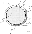
- FIG. 2c a schematic top view of an embodiment of the connecting device 1 is shown, in which the profile body 1d consists of lamellae placed one on top of the other, which form an annular closed lamellar profile.
- the lamellae each have a chamber 1c into which the filling material 1e can be filled.
- a very compact connecting device 1 or a very compact profile body 1d can advantageously be produced.
- the individual lamellae are designed to be flexible and are reinforced by the filling material 1e after it has hardened.
- the motor unit 2 is shown schematically as a hatched circle inside the connecting device 1, so that the inner wall 1a of the profile body 1d or of the respective lamellas is in contact with the motor unit.
- the housing 3 is in the Figure 2c not shown, but would rest against the outer wall 1b of the profile body 1d in the assembled state and thus enclose the profile body 1d and the motor unit 2 .
- the slats are connected to one another at their ends, so that closed slats are present in each case.
- the lamellae can also be open at their respective ends, so that there is a continuous transition between the individual lamellae, whereby the filled filling material 1e can flow between the individual chambers 1c and a balanced filling of the chambers 1c of the profile body 1d is made possible.
Landscapes
- Engineering & Computer Science (AREA)
- Power Engineering (AREA)
- General Engineering & Computer Science (AREA)
- Manufacturing & Machinery (AREA)
- Mechanical Engineering (AREA)
- Motor Or Generator Frames (AREA)
- Manufacture Of Motors, Generators (AREA)
Priority Applications (1)
| Application Number | Priority Date | Filing Date | Title |
|---|---|---|---|
| EP20184640.9A EP3937352B1 (fr) | 2020-07-08 | 2020-07-08 | Dispositif de raccordement permettant de raccorder une unité moteur à un boitier et procédé de raccordement de l'unité moteur au boitier à l'aide du dispositif de raccordement |
Applications Claiming Priority (1)
| Application Number | Priority Date | Filing Date | Title |
|---|---|---|---|
| EP20184640.9A EP3937352B1 (fr) | 2020-07-08 | 2020-07-08 | Dispositif de raccordement permettant de raccorder une unité moteur à un boitier et procédé de raccordement de l'unité moteur au boitier à l'aide du dispositif de raccordement |
Publications (2)
| Publication Number | Publication Date |
|---|---|
| EP3937352A1 true EP3937352A1 (fr) | 2022-01-12 |
| EP3937352B1 EP3937352B1 (fr) | 2022-08-31 |
Family
ID=71527622
Family Applications (1)
| Application Number | Title | Priority Date | Filing Date |
|---|---|---|---|
| EP20184640.9A Active EP3937352B1 (fr) | 2020-07-08 | 2020-07-08 | Dispositif de raccordement permettant de raccorder une unité moteur à un boitier et procédé de raccordement de l'unité moteur au boitier à l'aide du dispositif de raccordement |
Country Status (1)
| Country | Link |
|---|---|
| EP (1) | EP3937352B1 (fr) |
Citations (5)
| Publication number | Priority date | Publication date | Assignee | Title |
|---|---|---|---|---|
| US3798869A (en) * | 1970-03-06 | 1974-03-26 | E Nipp | Method of snap fitting channel members and foaming in place an interlock therebetween |
| JPS6189465A (ja) * | 1984-10-05 | 1986-05-07 | 株式会社日立製作所 | 冷蔵庫のフアンモ−タ用防振ゴム構造 |
| DE20217301U1 (de) * | 2002-11-09 | 2004-03-18 | SCHÜCO International KG | Eckverbinder für auf Gehrung geschnittene Hohlprofile eines Rahmens |
| DE102016111862A1 (de) * | 2015-07-06 | 2017-01-12 | Fanuc Corporation | Wellenstützvorrichtung, die abnehmbar an einem Motorkörper angebracht ist, und Motor, der mit der Wellenstützvorrichtung versehen ist |
| DE202017006928U1 (de) * | 2016-08-08 | 2018-11-16 | Carcoustics Techconsult Gmbh | Geräuschmindernde Kapsel zur Aufnahme einer Gebläsemotoreinheit eines Staubsaugers sowie Staubsauger |
-
2020
- 2020-07-08 EP EP20184640.9A patent/EP3937352B1/fr active Active
Patent Citations (5)
| Publication number | Priority date | Publication date | Assignee | Title |
|---|---|---|---|---|
| US3798869A (en) * | 1970-03-06 | 1974-03-26 | E Nipp | Method of snap fitting channel members and foaming in place an interlock therebetween |
| JPS6189465A (ja) * | 1984-10-05 | 1986-05-07 | 株式会社日立製作所 | 冷蔵庫のフアンモ−タ用防振ゴム構造 |
| DE20217301U1 (de) * | 2002-11-09 | 2004-03-18 | SCHÜCO International KG | Eckverbinder für auf Gehrung geschnittene Hohlprofile eines Rahmens |
| DE102016111862A1 (de) * | 2015-07-06 | 2017-01-12 | Fanuc Corporation | Wellenstützvorrichtung, die abnehmbar an einem Motorkörper angebracht ist, und Motor, der mit der Wellenstützvorrichtung versehen ist |
| DE202017006928U1 (de) * | 2016-08-08 | 2018-11-16 | Carcoustics Techconsult Gmbh | Geräuschmindernde Kapsel zur Aufnahme einer Gebläsemotoreinheit eines Staubsaugers sowie Staubsauger |
Also Published As
| Publication number | Publication date |
|---|---|
| EP3937352B1 (fr) | 2022-08-31 |
Similar Documents
| Publication | Publication Date | Title |
|---|---|---|
| DE2114802C3 (de) | Kardanbiegegelenk | |
| DE3640197C2 (fr) | ||
| DE4025505C2 (fr) | ||
| EP1320690B1 (fr) | Palier a collet pourvu d'un dispositif de centrage | |
| DE102012102775A1 (de) | Schraubrad für eine elektromechanische lenkvorrichtung | |
| EP0253968A1 (fr) | Procédé de fixation axiale d'un élément de construction sur un arbre respectivement dans un trou de forage | |
| DE102008021920A1 (de) | Exzenterschneckenpumpe | |
| DE69208640T2 (de) | Methode zur Herstellung von Kugelumlaufspindeln und Spindelwelleneinheiten | |
| DE102012102780A1 (de) | Verfahren zum herstellen eines schraubrads | |
| EP1354135B1 (fr) | Mini-palier de precision pour mini ou microsystemes et procede de montage de tels systemes | |
| DE68907884T2 (de) | Zickzack-Nähmaschine. | |
| DE102004056142A1 (de) | Spannvorrichtung zum Stabilisieren eines Bauteils | |
| EP3937352B1 (fr) | Dispositif de raccordement permettant de raccorder une unité moteur à un boitier et procédé de raccordement de l'unité moteur au boitier à l'aide du dispositif de raccordement | |
| DE102006055128A1 (de) | Elastisches Lager, insbesondere Getriebelager | |
| EP3096014B1 (fr) | Pompe a vis excentrique | |
| AT521959B1 (de) | Zahnrad | |
| EP0633128B1 (fr) | Procédé pour augmenter la tenue des liaisons mécaniques aux efforts de cisaillement | |
| EP1479927B1 (fr) | Palier lisse pour système télescopique et procédé pour sa fabrication | |
| EP3085961A1 (fr) | Pompe centrifuge à plusieurs etages | |
| DE102018205006A1 (de) | Zahnrad | |
| DE2541779A1 (de) | Stator fuer exzenterschneckenpumpen | |
| DE102008000728A1 (de) | Handwerkzeugmaschine, insbesondere handgeführte Schleifmaschine | |
| DE10304071B4 (de) | Verfahren zur Befestigung einer Magnethalterung an einer ein Zahnrad antreibenden Welle einer magnetgekuppelten Zahnradpumpe | |
| DE102005003153A1 (de) | Maschine mit demontierbarem Einbauelement | |
| DE102018203767A1 (de) | Zahnstange für ein Lenksystem |
Legal Events
| Date | Code | Title | Description |
|---|---|---|---|
| PUAI | Public reference made under article 153(3) epc to a published international application that has entered the european phase |
Free format text: ORIGINAL CODE: 0009012 |
|
| STAA | Information on the status of an ep patent application or granted ep patent |
Free format text: STATUS: EXAMINATION IS IN PROGRESS |
|
| 17P | Request for examination filed |
Effective date: 20210803 |
|
| AK | Designated contracting states |
Kind code of ref document: A1 Designated state(s): AL AT BE BG CH CY CZ DE DK EE ES FI FR GB GR HR HU IE IS IT LI LT LU LV MC MK MT NL NO PL PT RO RS SE SI SK SM TR |
|
| B565 | Issuance of search results under rule 164(2) epc |
Effective date: 20201209 |
|
| RIC1 | Information provided on ipc code assigned before grant |
Ipc: H02K 15/00 20060101ALN20220319BHEP Ipc: H02K 15/14 20060101ALN20220319BHEP Ipc: F16B 3/00 20060101ALI20220319BHEP Ipc: F16B 21/07 20060101ALI20220319BHEP Ipc: H02K 15/12 20060101ALI20220319BHEP Ipc: H02K 5/00 20060101AFI20220319BHEP |
|
| GRAP | Despatch of communication of intention to grant a patent |
Free format text: ORIGINAL CODE: EPIDOSNIGR1 |
|
| STAA | Information on the status of an ep patent application or granted ep patent |
Free format text: STATUS: GRANT OF PATENT IS INTENDED |
|
| RIC1 | Information provided on ipc code assigned before grant |
Ipc: H02K 15/00 20060101ALN20220407BHEP Ipc: H02K 15/14 20060101ALN20220407BHEP Ipc: F16B 3/00 20060101ALI20220407BHEP Ipc: F16B 21/07 20060101ALI20220407BHEP Ipc: H02K 15/12 20060101ALI20220407BHEP Ipc: H02K 5/00 20060101AFI20220407BHEP |
|
| INTG | Intention to grant announced |
Effective date: 20220506 |
|
| RIC1 | Information provided on ipc code assigned before grant |
Ipc: H02K 15/00 20060101ALN20220422BHEP Ipc: H02K 15/14 20060101ALN20220422BHEP Ipc: F16B 3/00 20060101ALI20220422BHEP Ipc: F16B 21/07 20060101ALI20220422BHEP Ipc: H02K 15/12 20060101ALI20220422BHEP Ipc: H02K 5/00 20060101AFI20220422BHEP |
|
| GRAS | Grant fee paid |
Free format text: ORIGINAL CODE: EPIDOSNIGR3 |
|
| GRAA | (expected) grant |
Free format text: ORIGINAL CODE: 0009210 |
|
| STAA | Information on the status of an ep patent application or granted ep patent |
Free format text: STATUS: THE PATENT HAS BEEN GRANTED |
|
| AK | Designated contracting states |
Kind code of ref document: B1 Designated state(s): AL AT BE BG CH CY CZ DE DK EE ES FI FR GB GR HR HU IE IS IT LI LT LU LV MC MK MT NL NO PL PT RO RS SE SI SK SM TR |
|
| REG | Reference to a national code |
Ref country code: CH Ref legal event code: EP Ref country code: GB Ref legal event code: FG4D Free format text: NOT ENGLISH |
|
| REG | Reference to a national code |
Ref country code: AT Ref legal event code: REF Ref document number: 1516028 Country of ref document: AT Kind code of ref document: T Effective date: 20220915 Ref country code: DE Ref legal event code: R096 Ref document number: 502020001602 Country of ref document: DE |
|
| REG | Reference to a national code |
Ref country code: IE Ref legal event code: FG4D Free format text: LANGUAGE OF EP DOCUMENT: GERMAN |
|
| REG | Reference to a national code |
Ref country code: LT Ref legal event code: MG9D |
|
| REG | Reference to a national code |
Ref country code: NL Ref legal event code: MP Effective date: 20220831 |
|
| PG25 | Lapsed in a contracting state [announced via postgrant information from national office to epo] |
Ref country code: SE Free format text: LAPSE BECAUSE OF FAILURE TO SUBMIT A TRANSLATION OF THE DESCRIPTION OR TO PAY THE FEE WITHIN THE PRESCRIBED TIME-LIMIT Effective date: 20220831 Ref country code: RS Free format text: LAPSE BECAUSE OF FAILURE TO SUBMIT A TRANSLATION OF THE DESCRIPTION OR TO PAY THE FEE WITHIN THE PRESCRIBED TIME-LIMIT Effective date: 20220831 Ref country code: NO Free format text: LAPSE BECAUSE OF FAILURE TO SUBMIT A TRANSLATION OF THE DESCRIPTION OR TO PAY THE FEE WITHIN THE PRESCRIBED TIME-LIMIT Effective date: 20221130 Ref country code: LV Free format text: LAPSE BECAUSE OF FAILURE TO SUBMIT A TRANSLATION OF THE DESCRIPTION OR TO PAY THE FEE WITHIN THE PRESCRIBED TIME-LIMIT Effective date: 20220831 Ref country code: LT Free format text: LAPSE BECAUSE OF FAILURE TO SUBMIT A TRANSLATION OF THE DESCRIPTION OR TO PAY THE FEE WITHIN THE PRESCRIBED TIME-LIMIT Effective date: 20220831 Ref country code: FI Free format text: LAPSE BECAUSE OF FAILURE TO SUBMIT A TRANSLATION OF THE DESCRIPTION OR TO PAY THE FEE WITHIN THE PRESCRIBED TIME-LIMIT Effective date: 20220831 |
|
| PG25 | Lapsed in a contracting state [announced via postgrant information from national office to epo] |
Ref country code: PL Free format text: LAPSE BECAUSE OF FAILURE TO SUBMIT A TRANSLATION OF THE DESCRIPTION OR TO PAY THE FEE WITHIN THE PRESCRIBED TIME-LIMIT Effective date: 20220831 Ref country code: IS Free format text: LAPSE BECAUSE OF FAILURE TO SUBMIT A TRANSLATION OF THE DESCRIPTION OR TO PAY THE FEE WITHIN THE PRESCRIBED TIME-LIMIT Effective date: 20221231 Ref country code: HR Free format text: LAPSE BECAUSE OF FAILURE TO SUBMIT A TRANSLATION OF THE DESCRIPTION OR TO PAY THE FEE WITHIN THE PRESCRIBED TIME-LIMIT Effective date: 20220831 Ref country code: GR Free format text: LAPSE BECAUSE OF FAILURE TO SUBMIT A TRANSLATION OF THE DESCRIPTION OR TO PAY THE FEE WITHIN THE PRESCRIBED TIME-LIMIT Effective date: 20221201 |
|
| PG25 | Lapsed in a contracting state [announced via postgrant information from national office to epo] |
Ref country code: SM Free format text: LAPSE BECAUSE OF FAILURE TO SUBMIT A TRANSLATION OF THE DESCRIPTION OR TO PAY THE FEE WITHIN THE PRESCRIBED TIME-LIMIT Effective date: 20220831 Ref country code: RO Free format text: LAPSE BECAUSE OF FAILURE TO SUBMIT A TRANSLATION OF THE DESCRIPTION OR TO PAY THE FEE WITHIN THE PRESCRIBED TIME-LIMIT Effective date: 20220831 Ref country code: PT Free format text: LAPSE BECAUSE OF FAILURE TO SUBMIT A TRANSLATION OF THE DESCRIPTION OR TO PAY THE FEE WITHIN THE PRESCRIBED TIME-LIMIT Effective date: 20230102 Ref country code: ES Free format text: LAPSE BECAUSE OF FAILURE TO SUBMIT A TRANSLATION OF THE DESCRIPTION OR TO PAY THE FEE WITHIN THE PRESCRIBED TIME-LIMIT Effective date: 20220831 Ref country code: DK Free format text: LAPSE BECAUSE OF FAILURE TO SUBMIT A TRANSLATION OF THE DESCRIPTION OR TO PAY THE FEE WITHIN THE PRESCRIBED TIME-LIMIT Effective date: 20220831 Ref country code: CZ Free format text: LAPSE BECAUSE OF FAILURE TO SUBMIT A TRANSLATION OF THE DESCRIPTION OR TO PAY THE FEE WITHIN THE PRESCRIBED TIME-LIMIT Effective date: 20220831 |
|
| PG25 | Lapsed in a contracting state [announced via postgrant information from national office to epo] |
Ref country code: SK Free format text: LAPSE BECAUSE OF FAILURE TO SUBMIT A TRANSLATION OF THE DESCRIPTION OR TO PAY THE FEE WITHIN THE PRESCRIBED TIME-LIMIT Effective date: 20220831 Ref country code: EE Free format text: LAPSE BECAUSE OF FAILURE TO SUBMIT A TRANSLATION OF THE DESCRIPTION OR TO PAY THE FEE WITHIN THE PRESCRIBED TIME-LIMIT Effective date: 20220831 |
|
| REG | Reference to a national code |
Ref country code: DE Ref legal event code: R097 Ref document number: 502020001602 Country of ref document: DE |
|
| PG25 | Lapsed in a contracting state [announced via postgrant information from national office to epo] |
Ref country code: NL Free format text: LAPSE BECAUSE OF FAILURE TO SUBMIT A TRANSLATION OF THE DESCRIPTION OR TO PAY THE FEE WITHIN THE PRESCRIBED TIME-LIMIT Effective date: 20220831 Ref country code: AL Free format text: LAPSE BECAUSE OF FAILURE TO SUBMIT A TRANSLATION OF THE DESCRIPTION OR TO PAY THE FEE WITHIN THE PRESCRIBED TIME-LIMIT Effective date: 20220831 |
|
| PLBE | No opposition filed within time limit |
Free format text: ORIGINAL CODE: 0009261 |
|
| STAA | Information on the status of an ep patent application or granted ep patent |
Free format text: STATUS: NO OPPOSITION FILED WITHIN TIME LIMIT |
|
| 26N | No opposition filed |
Effective date: 20230601 |
|
| PGFP | Annual fee paid to national office [announced via postgrant information from national office to epo] |
Ref country code: CH Payment date: 20230801 Year of fee payment: 4 |
|
| PGFP | Annual fee paid to national office [announced via postgrant information from national office to epo] |
Ref country code: DE Payment date: 20230720 Year of fee payment: 4 |
|
| PG25 | Lapsed in a contracting state [announced via postgrant information from national office to epo] |
Ref country code: MC Free format text: LAPSE BECAUSE OF FAILURE TO SUBMIT A TRANSLATION OF THE DESCRIPTION OR TO PAY THE FEE WITHIN THE PRESCRIBED TIME-LIMIT Effective date: 20220831 |
|
| PG25 | Lapsed in a contracting state [announced via postgrant information from national office to epo] |
Ref country code: MC Free format text: LAPSE BECAUSE OF FAILURE TO SUBMIT A TRANSLATION OF THE DESCRIPTION OR TO PAY THE FEE WITHIN THE PRESCRIBED TIME-LIMIT Effective date: 20220831 |
|
| REG | Reference to a national code |
Ref country code: BE Ref legal event code: MM Effective date: 20230731 |
|
| PG25 | Lapsed in a contracting state [announced via postgrant information from national office to epo] |
Ref country code: LU Free format text: LAPSE BECAUSE OF NON-PAYMENT OF DUE FEES Effective date: 20230708 |
|
| PG25 | Lapsed in a contracting state [announced via postgrant information from national office to epo] |
Ref country code: LU Free format text: LAPSE BECAUSE OF NON-PAYMENT OF DUE FEES Effective date: 20230708 |
|
| REG | Reference to a national code |
Ref country code: IE Ref legal event code: MM4A |
|
| PG25 | Lapsed in a contracting state [announced via postgrant information from national office to epo] |
Ref country code: IT Free format text: LAPSE BECAUSE OF FAILURE TO SUBMIT A TRANSLATION OF THE DESCRIPTION OR TO PAY THE FEE WITHIN THE PRESCRIBED TIME-LIMIT Effective date: 20220831 Ref country code: FR Free format text: LAPSE BECAUSE OF NON-PAYMENT OF DUE FEES Effective date: 20230731 Ref country code: BE Free format text: LAPSE BECAUSE OF NON-PAYMENT OF DUE FEES Effective date: 20230731 |
|
| PG25 | Lapsed in a contracting state [announced via postgrant information from national office to epo] |
Ref country code: IE Free format text: LAPSE BECAUSE OF NON-PAYMENT OF DUE FEES Effective date: 20230708 |
|
| PG25 | Lapsed in a contracting state [announced via postgrant information from national office to epo] |
Ref country code: IE Free format text: LAPSE BECAUSE OF NON-PAYMENT OF DUE FEES Effective date: 20230708 |