EP3937293A1 - Battery system and control method thereof - Google Patents
Battery system and control method thereof Download PDFInfo
- Publication number
- EP3937293A1 EP3937293A1 EP21193556.4A EP21193556A EP3937293A1 EP 3937293 A1 EP3937293 A1 EP 3937293A1 EP 21193556 A EP21193556 A EP 21193556A EP 3937293 A1 EP3937293 A1 EP 3937293A1
- Authority
- EP
- European Patent Office
- Prior art keywords
- battery
- voltage
- current
- battery module
- time period
- Prior art date
- Legal status (The legal status is an assumption and is not a legal conclusion. Google has not performed a legal analysis and makes no representation as to the accuracy of the status listed.)
- Pending
Links
Images


Classifications
-
- G—PHYSICS
- G01—MEASURING; TESTING
- G01R—MEASURING ELECTRIC VARIABLES; MEASURING MAGNETIC VARIABLES
- G01R31/00—Arrangements for testing electric properties; Arrangements for locating electric faults; Arrangements for electrical testing characterised by what is being tested not provided for elsewhere
- G01R31/36—Arrangements for testing, measuring or monitoring the electrical condition of accumulators or electric batteries, e.g. capacity or state of charge [SoC]
- G01R31/389—Measuring internal impedance, internal conductance or related variables
-
- H—ELECTRICITY
- H02—GENERATION; CONVERSION OR DISTRIBUTION OF ELECTRIC POWER
- H02J—CIRCUIT ARRANGEMENTS OR SYSTEMS FOR SUPPLYING OR DISTRIBUTING ELECTRIC POWER; SYSTEMS FOR STORING ELECTRIC ENERGY
- H02J7/00—Circuit arrangements for charging or depolarising batteries or for supplying loads from batteries
- H02J7/0029—Circuit arrangements for charging or depolarising batteries or for supplying loads from batteries with safety or protection devices or circuits
- H02J7/0031—Circuit arrangements for charging or depolarising batteries or for supplying loads from batteries with safety or protection devices or circuits using battery or load disconnect circuits
-
- H—ELECTRICITY
- H02—GENERATION; CONVERSION OR DISTRIBUTION OF ELECTRIC POWER
- H02J—CIRCUIT ARRANGEMENTS OR SYSTEMS FOR SUPPLYING OR DISTRIBUTING ELECTRIC POWER; SYSTEMS FOR STORING ELECTRIC ENERGY
- H02J7/00—Circuit arrangements for charging or depolarising batteries or for supplying loads from batteries
- H02J7/0013—Circuit arrangements for charging or depolarising batteries or for supplying loads from batteries acting upon several batteries simultaneously or sequentially
-
- G—PHYSICS
- G01—MEASURING; TESTING
- G01R—MEASURING ELECTRIC VARIABLES; MEASURING MAGNETIC VARIABLES
- G01R31/00—Arrangements for testing electric properties; Arrangements for locating electric faults; Arrangements for electrical testing characterised by what is being tested not provided for elsewhere
- G01R31/36—Arrangements for testing, measuring or monitoring the electrical condition of accumulators or electric batteries, e.g. capacity or state of charge [SoC]
- G01R31/396—Acquisition or processing of data for testing or for monitoring individual cells or groups of cells within a battery
-
- G—PHYSICS
- G01—MEASURING; TESTING
- G01R—MEASURING ELECTRIC VARIABLES; MEASURING MAGNETIC VARIABLES
- G01R31/00—Arrangements for testing electric properties; Arrangements for locating electric faults; Arrangements for electrical testing characterised by what is being tested not provided for elsewhere
- G01R31/50—Testing of electric apparatus, lines, cables or components for short-circuits, continuity, leakage current or incorrect line connections
- G01R31/52—Testing for short-circuits, leakage current or ground faults
-
- H—ELECTRICITY
- H01—ELECTRIC ELEMENTS
- H01M—PROCESSES OR MEANS, e.g. BATTERIES, FOR THE DIRECT CONVERSION OF CHEMICAL ENERGY INTO ELECTRICAL ENERGY
- H01M10/00—Secondary cells; Manufacture thereof
- H01M10/42—Methods or arrangements for servicing or maintenance of secondary cells or secondary half-cells
- H01M10/425—Structural combination with electronic components, e.g. electronic circuits integrated to the outside of the casing
-
- H—ELECTRICITY
- H01—ELECTRIC ELEMENTS
- H01M—PROCESSES OR MEANS, e.g. BATTERIES, FOR THE DIRECT CONVERSION OF CHEMICAL ENERGY INTO ELECTRICAL ENERGY
- H01M10/00—Secondary cells; Manufacture thereof
- H01M10/42—Methods or arrangements for servicing or maintenance of secondary cells or secondary half-cells
- H01M10/44—Methods for charging or discharging
- H01M10/441—Methods for charging or discharging for several batteries or cells simultaneously or sequentially
-
- H—ELECTRICITY
- H01—ELECTRIC ELEMENTS
- H01M—PROCESSES OR MEANS, e.g. BATTERIES, FOR THE DIRECT CONVERSION OF CHEMICAL ENERGY INTO ELECTRICAL ENERGY
- H01M10/00—Secondary cells; Manufacture thereof
- H01M10/42—Methods or arrangements for servicing or maintenance of secondary cells or secondary half-cells
- H01M10/48—Accumulators combined with arrangements for measuring, testing or indicating the condition of cells, e.g. the level or density of the electrolyte
- H01M10/482—Accumulators combined with arrangements for measuring, testing or indicating the condition of cells, e.g. the level or density of the electrolyte for several batteries or cells simultaneously or sequentially
-
- H—ELECTRICITY
- H01—ELECTRIC ELEMENTS
- H01M—PROCESSES OR MEANS, e.g. BATTERIES, FOR THE DIRECT CONVERSION OF CHEMICAL ENERGY INTO ELECTRICAL ENERGY
- H01M50/00—Constructional details or processes of manufacture of the non-active parts of electrochemical cells other than fuel cells, e.g. hybrid cells
- H01M50/50—Current conducting connections for cells or batteries
- H01M50/572—Means for preventing undesired use or discharge
-
- H—ELECTRICITY
- H02—GENERATION; CONVERSION OR DISTRIBUTION OF ELECTRIC POWER
- H02H—EMERGENCY PROTECTIVE CIRCUIT ARRANGEMENTS
- H02H7/00—Emergency protective circuit arrangements specially adapted for specific types of electric machines or apparatus or for sectionalised protection of cable or line systems, and effecting automatic switching in the event of an undesired change from normal working conditions
- H02H7/18—Emergency protective circuit arrangements specially adapted for specific types of electric machines or apparatus or for sectionalised protection of cable or line systems, and effecting automatic switching in the event of an undesired change from normal working conditions for batteries; for accumulators
-
- H—ELECTRICITY
- H02—GENERATION; CONVERSION OR DISTRIBUTION OF ELECTRIC POWER
- H02J—CIRCUIT ARRANGEMENTS OR SYSTEMS FOR SUPPLYING OR DISTRIBUTING ELECTRIC POWER; SYSTEMS FOR STORING ELECTRIC ENERGY
- H02J7/00—Circuit arrangements for charging or depolarising batteries or for supplying loads from batteries
- H02J7/0029—Circuit arrangements for charging or depolarising batteries or for supplying loads from batteries with safety or protection devices or circuits
- H02J7/00302—Overcharge protection
-
- H—ELECTRICITY
- H02—GENERATION; CONVERSION OR DISTRIBUTION OF ELECTRIC POWER
- H02J—CIRCUIT ARRANGEMENTS OR SYSTEMS FOR SUPPLYING OR DISTRIBUTING ELECTRIC POWER; SYSTEMS FOR STORING ELECTRIC ENERGY
- H02J7/00—Circuit arrangements for charging or depolarising batteries or for supplying loads from batteries
- H02J7/0029—Circuit arrangements for charging or depolarising batteries or for supplying loads from batteries with safety or protection devices or circuits
- H02J7/00304—Overcurrent protection
-
- H—ELECTRICITY
- H02—GENERATION; CONVERSION OR DISTRIBUTION OF ELECTRIC POWER
- H02J—CIRCUIT ARRANGEMENTS OR SYSTEMS FOR SUPPLYING OR DISTRIBUTING ELECTRIC POWER; SYSTEMS FOR STORING ELECTRIC ENERGY
- H02J7/00—Circuit arrangements for charging or depolarising batteries or for supplying loads from batteries
- H02J7/0047—Circuit arrangements for charging or depolarising batteries or for supplying loads from batteries with monitoring or indicating devices or circuits
-
- G—PHYSICS
- G01—MEASURING; TESTING
- G01R—MEASURING ELECTRIC VARIABLES; MEASURING MAGNETIC VARIABLES
- G01R31/00—Arrangements for testing electric properties; Arrangements for locating electric faults; Arrangements for electrical testing characterised by what is being tested not provided for elsewhere
- G01R31/36—Arrangements for testing, measuring or monitoring the electrical condition of accumulators or electric batteries, e.g. capacity or state of charge [SoC]
- G01R31/382—Arrangements for monitoring battery or accumulator variables, e.g. SoC
- G01R31/3842—Arrangements for monitoring battery or accumulator variables, e.g. SoC combining voltage and current measurements
-
- H—ELECTRICITY
- H01—ELECTRIC ELEMENTS
- H01M—PROCESSES OR MEANS, e.g. BATTERIES, FOR THE DIRECT CONVERSION OF CHEMICAL ENERGY INTO ELECTRICAL ENERGY
- H01M2200/00—Safety devices for primary or secondary batteries
-
- Y—GENERAL TAGGING OF NEW TECHNOLOGICAL DEVELOPMENTS; GENERAL TAGGING OF CROSS-SECTIONAL TECHNOLOGIES SPANNING OVER SEVERAL SECTIONS OF THE IPC; TECHNICAL SUBJECTS COVERED BY FORMER USPC CROSS-REFERENCE ART COLLECTIONS [XRACs] AND DIGESTS
- Y02—TECHNOLOGIES OR APPLICATIONS FOR MITIGATION OR ADAPTATION AGAINST CLIMATE CHANGE
- Y02E—REDUCTION OF GREENHOUSE GAS [GHG] EMISSIONS, RELATED TO ENERGY GENERATION, TRANSMISSION OR DISTRIBUTION
- Y02E60/00—Enabling technologies; Technologies with a potential or indirect contribution to GHG emissions mitigation
- Y02E60/10—Energy storage using batteries
Definitions
- the present invention relates to a battery system and a control method thereof.
- a battery is generally used as a power supply device for an operation of a portable electronic product, and a rechargeable battery, which is charged and is re-usable, is mainly used.
- the rechargeable battery is a chargeable and dischargeable battery, unlike a primary battery that cannot be charged.
- the rechargeable battery is used in a portable small electronic device, such as a portable phone or a notebook computer, or is widely used as a power source for driving a motor of a power tool, a vehicle, and the like.
- An internal part of the rechargeable battery may be formed of a positive electrode, a negative electrode, a separation film, an electrolyte, and the like, and a case may be formed of a metal plate or a pouch.
- a rechargeable battery having high energy density may cause a problem in safety, such as thermal runaway, and particularly, the case where the positive electrode and the negative electrode inside the rechargeable battery are short-circuited, so that the rechargeable battery is overheated is a representative example.
- the internal short is caused from a loss of a function of the separation film, and examples thereof include deformation by an external impact, metallic foreign substances included in a manufacturing process, and the forming of dendrite of lithium or copper by an electrochemical reaction.
- the present invention has been made in an effort to provide a battery system and a control method thereof, which are capable of rapidly detecting an internal short in a battery module and protecting a battery system from the internal short.
- An exemplary embodiment of the present invention provides a battery system including: a battery module including a plurality of battery sub modules connected in parallel between system terminals; a plurality of switches connected in series to the plurality of battery sub modules, respectively; a measuring unit measuring voltage values of the battery module and/or cells included in the battery module and current values which flow on the battery modules; a detecting unit determining whether or not an internal short occurs in the plurality of battery sub modules by monitoring the voltage values or the current values; and a control unit controlling, when the internal short occurs in at least one battery sub module of the plurality of battery sub modules, at least one switch corresponding to the at least one battery sub module among the plurality of switches in a non-conductive state.
- the detecting unit may determine each of a first voltage value in a first time period and a second voltage value in a second time period for the cells included in the plurality of battery sub modules based on the voltage values measured by the measuring unit and determine that the internal short occurs with respect to a cell in which a value acquired by subtracting the second voltage value from the first voltage value is equal to or larger than a first threshold among the cells, when the battery module is in constant current charging.
- the second time period may include a time period after the first time period.
- the detecting unit may perform detection of the internal short if a current change width in the first and second time periods of the plurality of battery sub modules is within a first range and a voltage change width in the first time period of the cells is within a second range, when the battery module is in the constant current charging.
- the detecting unit may determine each of a first current value in the first time period and a second current value in the second time period for the plurality of battery sub modules based on the current values measured by the measuring unit and determine that the internal short occurs with respect to a battery sub module in which a value acquired by subtracting the first current value from the second current value is equal to or larger than a third threshold among the plurality of battery sub modules, when the battery module is in constant voltage charging.
- the second time period may include a time period after the first time period.
- the detecting unit may perform the detection of the internal short if the current change width and the voltage change width of the plurality of battery sub modules in the first time period are within a predetermined range and a difference between the first voltage value in the first time period and the second voltage value in the second time period of the plurality of battery sub modules is equal to or smaller than a second threshold, when the battery module is in the constant voltage charging.
- the detecting unit may determine each of the first voltage value in the first time period and the second voltage value in the second time period for the cells included in the plurality of battery sub modules based on the voltage values measured by the measuring unit and determine that the internal short occurs with respect to a cell in which a value acquired by subtracting the second voltage value from the first voltage value is equal to or larger than a sixth threshold among the cells, after a predetermined time elapsed from a charging termination time point of the battery module.
- the second time period may include a time period after the first time period.
- the detecting unit may perform the detection of the internal short when there is no charging current supplied to the battery module during the first and second time periods and a discharging current of the battery module is equal to or smaller than a fourth threshold during the first and second time periods after the predetermined time elapsed from the charging termination time point of the battery module.
- the detecting unit may perform the detection of the internal short when the difference between the first current value in the first time period and the second current value in the second time period of the plurality of battery sub modules is equal to or smaller than a fifth threshold and the voltage change width in the first time period of the cells is within a fifth range after the predetermined time elapsed from the charging termination time point of the battery module.
- the detecting unit may compare the current values of the plurality of battery sub modules and determine that the internal short occurs with respect to a battery sub module having a larger current value by an eighth threshold or larger than the remaining battery sub modules among the plurality of battery sub modules, when the battery module is in the constant voltage charging.
- the detecting unit may perform the detection of the internal short if the current change width and the voltage change width of the plurality of battery sub modules in the first time period are within the predetermined range and the difference between the first voltage value in the first time period and the second voltage value in the second time period of the plurality of battery sub modules satisfies a seventh threshold or less, when the battery module is in the constant voltage charging.
- the current values of the plurality of battery sub modules may be current values in the second time period, and the second time period may include a time period after the first time period.
- a battery system including: a battery module connected between system terminals; a discharge circuit connected in parallel to the battery module between the system terminals and including a discharge switch and a discharge resistor connected to each other in series; a measuring unit measuring voltage values of the battery module and/or cells included in the battery module and current values which flow on the battery modules; a detecting unit determining whether or not an internal short occurs in the battery module by monitoring the voltage values or the current values; and a control unit controlling the discharge switch so that the voltage value of the battery module is dropped to a predetermined value or less when the internal short occurs in the battery module.
- the detecting unit may determine each of a first voltage value in a first time period and a second voltage value in a second time period for the cells included in the plurality of battery modules based on the voltage values measured by the measuring unit and determine that the internal short occurs with respect to a cell in which a value acquired by subtracting the second voltage value from the first voltage value is equal to or larger than a first threshold among the cells, when the battery module is in a constant current charging.
- the second time period may include a time period after the first time period.
- the battery module may include a plurality of battery sub modules connected to each other in parallel and each including a plurality of cells.
- the detecting unit may perform detection of the internal short if a current change width in the first and second time periods of the plurality of battery sub modules is within a first range and a voltage change width in the first time period of the plurality of cells is within a second range, when the battery module is in the constant current charging.
- the detecting unit may determine each of a first current value in the first time period and a second current value in the second time period for the plurality of battery sub modules based on the current values measured by the measuring unit and determine that the internal short occurs with respect to a battery sub module in which a value acquired by subtracting the first current value from the second current value is equal to or larger than a third threshold among the plurality of battery sub modules, when the battery module is in constant voltage charging.
- the second time period may include a time period after the first time period.
- the detecting unit may perform the detection of the internal short if the current change width and the voltage change width of the plurality of battery sub modules in the first time period are within a predetermined range and a difference between the first voltage value in the first time period and the second voltage value in the second time period of the plurality of battery sub modules is equal to or smaller than a second threshold, when the battery module is in the constant voltage charging.
- the detecting unit may determine each of the first voltage value in the first time period and the second voltage value in the second time period for the cells included in the plurality of battery sub modules based on the voltage values measured by the measuring unit and determine that the internal short occurs with respect to a cell in which a value acquired by subtracting the second voltage value from the first voltage value is equal to or larger than a sixth threshold among the cells, after a predetermined time elapsed from a charging termination time point of the battery module.
- the second time period may include a time period after the first time period.
- the detecting unit may perform the detection of the internal short when there is no charging current supplied to the battery module during the first and second time periods and a discharging current of the battery module is equal to or smaller than a fourth threshold during the first and second time periods after the predetermined time elapsed from the charging termination time point of the battery module after the predetermined time elapsed from the charging termination time point of the battery module.
- the detecting unit may perform the detection of the internal short when the difference between the first current value in the first time period and the second current value in the second time period of the plurality of battery sub modules is equal to or smaller than a fifth threshold and the voltage change width in the first time period of the plurality of cells is within a fifth range after the predetermined time elapsed from the charging termination time point of the battery module.
- the detecting unit may compare the current values of the plurality of battery sub modules and determine that the internal short occurs with respect to a battery sub module having a larger current value by an eighth threshold or larger than the remaining battery sub modules among the plurality of battery sub modules, when the battery module is in the constant voltage charging.
- the detecting unit may perform the detection of the internal short if the current change width and the voltage change width of the plurality of battery sub modules in the first time period are within the predetermined range and the difference between the first voltage value in the first time period and the second voltage value in the second time period of the plurality of battery sub modules satisfies a seventh threshold or less, when the battery module is in the constant voltage charging.
- the current values of the plurality of battery sub modules may be current values in the second time period, and the second time period may include a time period after the first time period.
- Yet another exemplary embodiment of the present invention provides a control method of a battery system including a battery module including a plurality of battery sub modules connected in parallel between system terminals and a plurality of switches connected in series to the plurality of battery sub modules, respectively, including: measuring voltage values of the plurality of battery sub modules and/or cells included in the plurality of battery sub modules and current values which flow on the battery module; detecting occurrence of an internal short in the battery module by monitoring the voltage values or the current values; and controlling the plurality of switches so as to electrically separate at least one battery sub module in which the internal short occurs among the plurality of battery sub modules from the system terminals when the internal short occurs in the battery module.
- the detecting may include determining each of a first voltage value in a first time period and a second voltage value in a second time period with respect to the cells included in the plurality of battery sub modules based on the voltage values measured by the measuring unit when the battery module is in constant current charging, and determining that the internal short occurs with respect to a cell in which a value acquired by subtracting the second voltage value from the first voltage value is equal to or larger than a first threshold among the cells.
- the second time period may include a time period after the first time period.
- the detecting may be performed if a current change width in the first and second time periods of the plurality of battery sub modules is within a first range and a voltage change width in the first time period of the cells is within a second range, when the battery module is in the constant current charging.
- the detecting may include determining each of a first current value in a first time period and a second current value in a second time period with respect to the plurality of battery sub modules based on the current values measured by the measuring unit when the battery module is in constant voltage charging, and determining that the internal short occurs in a battery sub module in which a value acquired by subtracting the first current value from the second current value among the plurality of battery sub modules is equal to or larger than a third threshold.
- the second time period may include a time period after the first time period.
- the detecting may be performed if the current change width and the voltage change width of the plurality of battery sub modules in the first time period are within a predetermined range and a difference between the first voltage value in the first time period and the second voltage value in the second time period of the plurality of battery sub modules is equal to or smaller than a second threshold, when the battery module is in the constant voltage charging.
- the detecting may include determining each of a first voltage value in a first time period and a second voltage value in a second time period with respect to the cells included in the plurality of battery sub modules based on the voltage values measured by the measuring unit after a predetermined time elapsed from a charging termination time point of the battery module, and determining that the internal short occurs with respect to a cell in which a value acquired by subtracting the second voltage value from the first voltage value is equal to or larger than a sixth threshold value among the cells.
- the second time period may include a time period after the first time period.
- the detecting may be performed when there is no charging current supplied to the battery module during the first and second time periods and a discharging current of the battery module is equal to or smaller than a fourth threshold during the first and second time periods after the predetermined time elapsed from the charging termination time point of the battery module.
- the detecting may be performed when the difference between the first current value in the first time period and the second current value in the second time period of the plurality of battery sub modules is equal to or smaller than a fifth threshold and the voltage change width in the first time period of the cells is within a fifth range after the predetermined time elapsed from the charging termination time point of the battery module.
- the detecting may include comparing current values of the plurality of battery sub modules when the battery module is in constant voltage charging, and determining that the internal short occurs in a battery sub module having a larger current value by an eighth threshold or larger than the remaining battery sub modules among the plurality of battery sub modules.
- the detecting may be performed if the current change width and the voltage change width of the plurality of battery sub modules in the first time period are within the predetermined range and the difference between the first voltage value in the first time period and the second voltage value in the second time period of the plurality of battery sub modules satisfies a seventh threshold or less, when the battery module is in the constant voltage charging.
- the current values of the plurality of battery sub modules may be current values in the second time period, and the second time period may include a time period after the first time period.
- Still yet another exemplary embodiment of the present invention provides a control method of a battery system including a battery module connected between system terminals and a discharge circuit connected to the battery module in parallel between the system terminals, including: measuring voltage values of the battery module and/or cells included in the battery module and current values which flow on the battery modules; detecting occurrence of an internal short in the battery module by monitoring the voltage values or the current values; and operating a discharge circuit so that the voltage value of the battery module is dropped to a predetermined value or less when the internal short occurs in the battery module.
- the detecting may include determining each of a first voltage value in a first time period and a second voltage value in a second time period with respect to the cells included in the plurality of battery sub modules based on the voltage values measured by the measuring unit when the battery module is in constant current charging, and determining that the internal short occurs with respect to a cell in which a value acquired by subtracting the second voltage value from the first voltage value is equal to or larger than a first threshold among the cells.
- the second time period may include a time period after the first time period.
- the battery module may include a plurality of battery sub modules connected to each other in parallel and each including a plurality of cells.
- the detecting may be performed if a current change width in the first and second time periods of the plurality of battery sub modules is within a first range and a voltage change width in the first time period of the cells is within a second range, when the battery module is in the constant current charging.
- the detecting may include determining each of a first current value in a first time period and a second current value in a second time period with respect to the plurality of battery sub modules based on the current values measured by the measuring unit when the battery module is in constant voltage charging, and determining that the internal short occurs in a battery sub module in which a value acquired by subtracting the first current value from the second current value among the plurality of battery sub modules is equal to or larger than a third threshold.
- the second time period may include a time period after the first time period.
- the detecting may be performed if the current change width and the voltage change width of the plurality of battery sub modules in the first time period are within a predetermined range and a difference between the first voltage value in the first time period and the second voltage value in the second time period of the plurality of battery sub modules is equal to or smaller than a second threshold, when the battery module is in the constant voltage charging.
- the detecting may include determining each of a first voltage value in a first time period and a second voltage value in a second time period with respect to the cells included in the plurality of battery sub modules based on the voltage values measured by the measuring unit after a predetermined time elapsed from a charging termination time point of the battery module, and determining that the internal short occurs with respect to a cell in which a value acquired by subtracting the second voltage value from the first voltage value is equal to or larger than a sixth threshold value among the cells.
- the second time period may include a time period after the first time period.
- the detecting may be performed when there is no charging current supplied to the battery module during the first and second time periods and a discharging current of the battery module is equal to or smaller than a fourth threshold during the first and second time periods after the predetermined time elapsed from the charging termination time point of the battery module.
- the detecting may be performed when the difference between the first current value in the first time period and the second current value in the second time period of the plurality of battery sub modules is equal to or smaller than a fifth threshold and the voltage change width in the first time period of the cells is within a fifth range after the predetermined time elapsed from the charging termination time point of the battery module.
- the detecting may include comparing current values of the plurality of battery sub modules when the battery module is in constant voltage charging, and determining that the internal short occurs in a battery sub module having a larger current value by an eighth threshold or larger than the remaining battery sub modules among the plurality of battery sub modules.
- the detecting may be performed if the current change width and the voltage change width of the plurality of battery sub modules in the first time period are within the predetermined range and the difference between the first voltage value in the first time period and the second voltage value in the second time period of the plurality of battery sub modules satisfies a seventh threshold or less, when the battery module is in the constant voltage charging.
- the current values of the plurality of battery sub modules may be current values in the second time period, and the second time period may include a time period after the first time period.
- a battery system comprising: a battery module including a plurality of battery sub modules connected in parallel between system terminals; a plurality of switches connected in series to the plurality of battery sub modules, respectively; a measuring unit arranged to measure voltage values of the battery module and/or cells included in the battery module and/or current values which flow on the battery modules; a detecting unit arranged to determine whether or not an internal short occurs in the plurality of battery sub modules by monitoring the voltage values or the current values; and a control unit arranged to control, when the internal short occurs in at least one battery sub module of the plurality of battery sub modules, at least one switch corresponding to the at least one battery sub module in a non-conductive state among the plurality of switches.
- the detecting unit is arranged to determine each of a first voltage value in a first time period and a second voltage value in a second time period for the cells included in the plurality of battery sub modules based on the voltage values measured by the measuring unit and to determine that the internal short occurs with respect to a cell in which a value acquired by subtracting the second voltage value from the first voltage value is equal to or larger than a first threshold among the cells, when the battery module is in constant current charging, and the second time period includes a time period after the first time period.
- the detecting unit is arranged to perform detection of the internal short if a current change width in the first and second time periods of the plurality of battery sub modules is within a first range and a voltage change width in the first time period of the cells is within a second range, when the battery module is in the constant current charging.
- the detecting unit is arranged to determine each of a first current value in the first time period and a second current value in the second time period for the plurality of battery sub modules based on the current values measured by the measuring unit and to determine that the internal short occurs with respect to a battery sub module in which a value acquired by subtracting the first current value from the second current value is equal to or larger than a third threshold among the plurality of battery sub modules, when the battery module is in constant voltage charging, and the second time period includes a time period after the first time period.
- the detecting unit is arranged to perform the detection of the internal short if the current change width and the voltage change width of the plurality of battery sub modules in the first time period are within a predetermined range and a difference between the first voltage value in the first time period and the second voltage value in the second time period of the plurality of battery sub modules is equal to or smaller than a second threshold, when the battery module is in the constant voltage charging.
- the detecting unit is arranged to determine each of the first voltage value in the first time period and the second voltage value in the second time period for the cells included in the plurality of battery sub modules based on the voltage values measured by the measuring unit and to determine that the internal short occurs with respect to a cell in which a value acquired by subtracting the second voltage value from the first voltage value is equal to or larger than a sixth threshold among the cells, after a predetermined time elapsed from a charging termination time point of the battery module, and the second time period includes a time period after the first time period.
- the detecting unit is arranged to perform the detection of the internal short when there is no charging current supplied to the battery module during the first and second time periods and a discharging current of the battery module is equal to or smaller than a fourth threshold during the first and second time periods after the predetermined time elapsed from the charging termination time point of the battery module.
- the detecting unit is arranged to perform the detection of the internal short when the difference between the first current value in the first time period and the second current value in the second time period of the plurality of battery sub modules is equal to or smaller than a fifth threshold and the voltage change width in the first time period of the cells is within a fifth range after the predetermined time elapsed from the charging termination time point of the battery module.
- the detecting unit is arranged to compare the current values of the plurality of battery sub modules and to determine that the internal short occurs with respect to a battery sub module having a larger current value by an eighth threshold or larger than the remaining battery sub modules among the plurality of battery sub modules, when the battery module is in the constant voltage charging.
- the detecting unit is arranged to perform the detection of the internal short if the current change width and the voltage change width of the plurality of battery sub modules in the first time period are within the predetermined range and the difference between the first voltage value in the first time period and the second voltage value in the second time period of the plurality of battery sub modules satisfies a seventh threshold or less, when the battery module is in the constant voltage charging, the current values of the plurality of battery sub modules are current values in the second time period, and the second time period includes a time period after the first time period.
- a control method of a battery system including a battery module including a plurality of battery sub modules connected in parallel between system terminals, the control method comprising: measuring voltage values of the plurality of battery sub modules and/or cells included in the plurality of battery sub modules and current values which flow on the battery module; detecting occurrence of an internal short in the battery module by monitoring the voltage values or the current values; and electrically separating at least one battery sub module in which the internal short occurs among the plurality of battery sub modules from the system terminals when the internal short occurs in the battery module.
- a battery system can be safely protected from the internal short.
- first and second are used to describe various elements, these elements should not be limited by these terms. These terms are only used to distinguish one element from another element. For example, a first element may be named a second element and, similarly, a second element may be named a first element, without departing from the scope of the present invention.
- the term “and/or” includes any and all combinations of one or more of the associated listed items. Expressions such as “at least one of,” when preceding a list of elements, modify the entire list of elements and do not modify the individual elements of the list.
- FIGS. 1 to 3 a battery system according to an exemplary embodiment of the present invention will be described in detail with reference to FIGS. 1 to 3 .
- FIG. 1 is a diagram illustrating a configuration of a battery system according to an exemplary embodiment of the present invention. Further, FIG. 2 illustrates an example of a battery module of FIG. 1 .
- a battery system 1 may include a battery module 10 and a battery control apparatus 20.
- the battery module 10 may include one or more secondary battery cells (hereinafter, referred to as a "cell”) connected in series and/or in parallel.
- a cell secondary battery cells
- the battery module 10 includes a plurality of battery sub modules 11 connected in parallel between two system terminals T+ and T-. Further, each battery sub module 11 includes a plurality of cell banks 13 connected to each other in series and each cell bank 13 includes a plurality of cells, e.g., two cells 100 connected to each other in parallel.
- FIG. 2 illustrates an example of the battery module 10 and a configuration of the battery module 10 in embodiments is not limited thereto.
- the battery module 10 may be configured by a single cell. Further, for example, the battery module 10 may be constituted only by a plurality of cells connected in series and a plurality of battery sub modules each constituted by the plurality of cells connected to each other in series may be configured to be connected to each other in parallel.
- the battery module 10 may be connected to an external charge device (not illustrated) or a load through the system terminals T+ and T- and charged by the charging device or discharged by the load.
- the battery module 10 is charged by one or more charging methods among constant current (CC) charging, in which charging is performed with a constant current from an initial stage to a completion stage of the charging, constant voltage (CV) charging, in which the charging is performed with a constant voltage from the initial stage to the completion stage of the charging, and CC-CV charging, in which the battery module is charged with the constant current at the initial stage of the charging and with the constant voltage at an end stage of the charging.
- CC constant current
- CV constant voltage
- CC-CV charging constant voltage
- FIG. 3 illustrates an equivalent circuit of a secondary battery cell constituting the battery module of FIG. 2 .
- each cell 100 constituting the battery module 10 may include an internal resistance R B , and the internal resistance R B may have a resistance value of several m ⁇ to several hundreds of m.
- the internal resistance R B may have a resistance value of several m ⁇ to several hundreds of m.
- FIGS. 4A to 4C are diagrams for describing changes in voltage and current depending on occurrence of an internal short of a secondary battery cell constituting the battery module of FIG. 2 .
- a charging current I supplied to the cell 100 has a predetermined value, and a voltage V of the cell 100 gradually increases.
- CC constant current
- the internal short Is occurs in the cell 100
- the phenomenon occurs because equivalent resistance of the cell 100, that is, combined resistance of the internal resistance R B and the short resistance Rs of the cell 100, is momentarily changed due to the internal short of the cell 100.
- the voltage V of the cell 100 has a predetermined value and the charging current I of the cell 100 gradually decreases.
- the charging current I of the cell 100 sharply increases and then decreases again. Referring to FIG. 3 , the phenomenon occurs because equivalent resistance of the cell 100, that is, the combined resistance of the internal resistance R B and the short resistance Rs of the cell 100, is momentarily changed due to the internal short of the cell 100.
- the voltage V of the cell 100 is constantly maintained for a predetermined time and then gradually decreases.
- the internal short Is occurs in the cell 100
- the phenomenon occurs because equivalent resistance of the cell 100, that is, the combined resistance of the internal resistance R B and the short resistance Rs of the cell 100, is momentarily changed due to the internal short of the cell 100.
- an internal short of the cell 100 causes a change in voltage or current of the cell 100, which may be measured even in the battery module 10 constituted by the plurality of cells 100 as illustrated in FIG. 2 .
- the battery module 10 is CC-charged or the battery module 10 is in the open voltage state
- the internal short occurs in a specific cell 100
- the voltage of a battery sub module 11 including the corresponding cell 100 may also decrease.
- current which flows on the battery sub module 11 including the corresponding cell 100 or the battery module 10 may also increase.
- the changes in voltage and/or current of the battery module 10 are monitored to detect the cell 100 or the battery sub module 11 in which the internal short occurs.
- the battery control apparatus 20 may detect the internal short of the battery module 10 and execute a protection function for protecting the battery module 10 from a dangerous situation caused by the internal short.
- the battery control apparatus 20 may include a measuring unit 21, a detecting unit 22, and a control unit 23.
- the measuring unit 21 continuously measures a charging start time point and a charging termination time point of the battery module 10 and a voltage, a current, and a temperature of the battery module 10 and transfers the measured voltage values, current values, temperature values, charging start time point, charging termination time point, etc., to the detecting unit 22.
- the measuring unit 21 may discretely perform the measurement. A predetermined time period may exist between two measurement time points and a change of the time period may be changed.
- the measuring unit 21 may detect at least one of the voltage, the current, and the temperature at one measurement time point.
- the voltage values of the battery module 10 measured by the measuring unit 21 may include voltage values of respective cells 100 constituting the battery module 10. Further, the voltage values of the battery module 10 measured by the measuring unit 21 may include voltage values of respective battery sub modules 11 constituting the battery module 10. In addition, the voltage values of the battery module 10 measured by the measuring unit 21 may include voltage values of the entire battery module 10, i.e., a voltage value between the system terminals T+ and T-.
- FIG. 5 illustrates an example of measuring a voltage value of the battery module 10 illustrated in FIG. 2 through the measuring unit 21.
- the measuring unit 21 may be electrically connected to both ends (or both ends of each cell bank 13) of each cell 100 constituting the battery module 10 and thus measure the voltage values of both ends of each cell 100 (or each cell bank 13) and/or the battery sub module 11.
- the current values of the battery module 10 measured by the measuring unit 21 may include current values acquired by measuring charging current supplied from the charging device to the entire battery module 10 and/or discharging current supplied from the battery module 10 to the load. Further, the current values of the battery module 10 measured by the measuring unit 21 may include current values acquired by measuring the charging current supplied from the charging device for each battery sub module 11 constituting the battery module 10 and/or discharging current supplied to the external load for each battery sub module 11.
- FIGS. 6A and 6B illustrate examples of measuring a current value of the battery module 10 illustrated in FIG. 2 through the measuring unit 21.
- the battery system 1 may further include shunt resistors 31 connected in series to each of the battery sub modules 11.
- the charging current or discharging current flowing on each battery sub module 11 also flows even on the corresponding shunt resistor 31.
- the measuring unit 21 may measure the charging current or the discharging current which flows on the corresponding battery sub module 11 from a voltage drop caused by each shunt resistor 31.
- the battery system 1 may further include shunt resistors 31 connected in series between any one of the system terminals T+ and T- and the battery module 10.
- the current which flows between the entire battery module 10 and the charging device or between the entire battery module 10 and the load may flow on the shunt resistor 31 and the measuring unit 31 may measure the current which flows between the entire battery module 10 and the charging device or between the entire battery module 10 and the load from the voltage drop caused by the shunt resistor 31.
- the detecting unit 22 receives the voltage values, the current values, the temperature values, etc., measured for the battery module 10 from the measuring unit 21 and stores the received voltage values, current values, temperature values, etc., in a memory (not illustrated).
- a change aspect of the voltage or current of each cell 100 depending on the internal short varies depending on whether the battery module 10 is being charged and a charging scheme (CC charging and CV charging). Therefore, the battery control apparatus 20 checks whether the current battery module 10 is being charged and the charging scheme when the battery module 10 is being charged in order to detect the internal short. That is, the detecting unit 22 determines whether the current battery module 10 is any one of the CC charging state, the CV charging state, and the open voltage state (no load or low load state) by using the measured voltage values and current values of the battery module 10.
- the detecting unit 22 detects the occurrence of the internal short of each cell 100 by monitoring the change in voltage of each cell 100 constituting the battery module 10 when the battery module 10 is in the CC charging.
- the detecting unit 22 may determine a first voltage group and a second voltage group constituted by the voltage values measured in different time periods for each cell 100 from the voltage values of each cell 100, which are measured by the measuring unit 21 while the battery module 10 is in the CC charging and detect the occurrence of the internal short in the corresponding cell 100 by comparing the first voltage group and the second voltage group for the same cell 100. That is, when the difference between an average of the voltage values included in the first voltage group and the average of the voltage values included in the second voltage group for the same cell 100 is larger than or equal to a threshold, the detecting unit 22 may determine that the internal short occurs in the corresponding cell 100.
- each of the first voltage group and the second voltage group may include a plurality of voltage values measured for the corresponding cell 100 during a predetermined period and the voltage values included in the first voltage group may be voltage values measured before the voltage values included in the second voltage group.
- a method for determining the first and second voltage groups will be described in detail with reference to FIG. 8 to be described below.
- the detecting unit 22 may select a first voltage value and a second voltage value measured during different time periods, respectively for each cell 100 from the voltage values of each cell 100, which are measured by the measuring unit 21 while the battery module 10 is in the CC charging and detect the internal short of the corresponding cell 100 by comparing the first voltage value and the second voltage value for the same cell 100. That is, when the difference between the first voltage value and the second voltage value is larger than or equal to a threshold for the same cell 100, the detecting unit 22 may determine that the internal short occurs in the corresponding cell 100.
- the first and second voltage values are instantaneous voltage values and the first voltage value may be a voltage value measured before the second voltage value.
- the detecting unit 22 detects the occurrence of the internal short of the battery module 10 by monitoring the change in current of the battery module 10 when the battery module 10 is in the CV charging.
- the detecting unit 22 may determine a first current group and a second current group constituted by the current values measured in different time periods for each battery sub module 11 from the current values (see the current measuring scheme of FIG. 6A ) measured for each battery sub module 11 by the measuring unit 21 while the battery module 10 is in the CV charging and detect the internal short of the corresponding battery sub module 11 by comparing the first current group and the second current group for the same battery sub module 11. That is, when the difference between the average of the current values included in the first current group and the average of the current values included in the second current group for the same battery sub module 11 is larger than or equal to a threshold, the detecting unit 22 may determine that the internal short occurs in the cell 100 included in the corresponding battery sub module 11.
- each of the first current group and the second current group may include a plurality of current values measured for the corresponding battery sub module 11 during a predetermined period and the current values included in the first current group may be current values measured before the current values included in the second current group.
- a method for determining the first and second current groups will be described in detail with reference to FIG. 8 to be described below.
- the detecting unit 22 may select the first current value and the second current value measured in different time periods, respectively for each battery sub module 11 from the current values (see the current measuring scheme of FIG. 6A ) measured for each battery sub module 11 by the measuring unit 21 while the battery module 10 is in the CV charging and detect the internal short of the corresponding battery sub module 11 by comparing the first current value and the second current value for the same battery sub module 11. That is, when the difference between the first current value and the second current value is larger than or equal to a threshold for the same battery sub module 11, the detecting unit 22 may determine that the internal short occurs in the cell 100 included in the corresponding battery sub module 11.
- the first and second current values are instantaneous current values and the first current value may be a current value measured before the second current value.
- the detecting unit 22 may compare the current values (see the current measuring scheme of FIG. 6A ) of the battery sub modules 11, which are measured by the measuring unit 21 while the battery module 10 is in the CV charging and determine that the internal short occurs for the battery sub module 11 having a larger current value by a predetermined value or larger than another battery sub module 11.
- the detecting unit 22 may determine the first current group and the second current group constituted by the current values measured during different time periods from the current values (see the current measuring scheme of FIG. 6B ) measured for the battery module 10 by the measuring unit 21 while the battery module 10 is in the CV charging and detect the internal short in the battery module 10 by comparing the first current group and the second current group with each other. That is, when the difference between the average of the current values included in the first current group and the average of the current values included in the second current group is larger than or equal to a threshold, the detecting unit 22 may determine that the internal short occurs in the cell 100 included in the battery module 10.
- each of the first current group and the second current group may include a plurality of current values measured for the battery module 10 during a predetermined period and the current values included in the first current group may be current values measured before the current values included in the second current group.
- a method for determining the first and second current groups will be described in detail with reference to FIG. 8 to be described below.
- the detecting unit 22 may select the first current value and the second current value measured during different time periods, respectively for each battery sub module 11 from the current values (see the current measuring scheme of FIG. 6B ) measured for the battery module 10 by the measuring unit 21 while the battery module 10 is in the CV charging and detect the internal short in the battery module 10 by comparing the first current value and the second current value with each other. That is, when the difference between the first current value and the second current value is larger than or equal to a threshold, the detecting unit 22 may determine that the internal short occurs in the cell 100 included in the battery module 10.
- the first and second current values are instantaneous current values of the battery module 10 and the first current value may be a current value measured before the second current value.
- the current which flows on the battery module 10 configured by connecting a plurality of cells 100 in series and/or in parallel is measured in units of the battery sub module 11 as illustrated in FIG. 6A or measured in units of the battery module 10 as illustrated in FIG. 6B .
- FIG. 2 when the cells 100 (or cell banks 13) included in each battery sub module 11 are connected to each other in series, the same current flows on the cells 100 (or cell banks 13) included in the same battery sub module 11, and as a result, there is a problem in that it is difficult to determine whether the internal short occurs in units of the cell 100 (or cell bank 13) even though the current which flows on each cell 100 (or cell bank 13) is measured.
- the detecting unit 22 may determine whether the internal short occurs by monitoring the current which flows on each battery sub module 11 or the current which flows on the battery module 10. In the former case, the detecting unit 22 may specify the battery sub module 11 including the cell 100 in which the internal short occurs.
- the detecting unit 22 detects the occurrence of the internal short of the battery module 10 by monitoring the change in voltage of each cell 100 when the charging of the battery module 10 is terminated and the battery module 10 is in the current open voltage state.
- the detecting unit 22 may determine a first voltage group and a second voltage group constituted by the voltage values measured in different time periods for each cell 100 from the voltage values of each cell 100, which are measured by the measuring unit 21 while the battery module 10 is in the open voltage state and detect the internal short of the corresponding cell 100 by comparing the first voltage group and the second voltage group for the same cell 100. That is, when the difference between an average of the voltage values included in the first voltage group and the average of the voltage values included in the second voltage group for the same cell 100 is larger than or equal to a threshold, the detecting unit 22 may determine that the internal short occurs in the corresponding cell 100.
- each of the first voltage group and the second voltage group may include a plurality of voltage values measured for the corresponding cell 100 during a predetermined period and the voltage values included in the first voltage group may be voltage values measured before the voltage values included in the second voltage group.
- a method for determining the first and second voltage groups will be described in detail with reference to FIG. 4 to be described below.
- the detecting unit 22 may select a first voltage value and a second voltage value measured during different time periods, respectively for each cell 100 from the voltage values of each cell 100, which are measured by the measuring unit 21 while the battery module 10 is in the open voltage state and detect the internal short of the corresponding cell 100 by comparing the first voltage value and the second voltage value for the same cell 100. That is, when the difference between the first voltage value and the second voltage value is larger than or equal to a threshold for the same cell 100, the detecting unit 22 may determine that the internal short occurs in the corresponding cell 100.
- the first and second voltage values are instantaneous voltage values and the first voltage value may be a voltage value measured before the second voltage value.
- voltage values used for determining the internal short may be voltage values measured after a predetermined time elapsed from a charging termination time point of the battery module 10.
- the predetermined time may mean a time until the internal short may be determined after charging termination and when the internal short is determined by using voltage values measured before the predetermined time, determination accuracy may be degraded.
- the detecting unit 22 When the detecting unit 22 detects the occurrence of the internal short of the battery module 10 by using the aforementioned schemes, the detecting unit 22 generates a detection signal Ds including the state of the battery module 10 and whether the internal short Is occurs. A specific process of detecting the internal short of the battery module 10 by the detecting unit 22 will be described in detail with reference to FIGS. 9 to 12 to be described below.
- the voltage of the battery sub module 11 including the cell 100 in which the internal short occurs instantaneously decreases, and as a result, a current for compensating for the voltage drop in the battery sub module 11 in which the internal short occurs may flow from the adjacent battery sub modules 11. Therefore, a situation may occur in which the cells 100 in the battery sub module 11 in which the internal short occurs are charged with the flowing current and normal cells 100 in the battery sub module 11 in which the internal short occurs are overcharged.
- control unit 23 may execute protection operations for protecting the battery module 10 from the dangerous situation caused by the internal short, based on the detection signal Ds generated by the detecting unit 22.
- FIGS. 7A and 7B are diagrams for describing a protection operation of a battery module 10 for an internal short of a battery control apparatus 20.
- the battery system 1 may further include a main switch 32 connected in series between any one of the system terminals T+ and T- and the battery module 10.
- the battery system 1 may further include a switch 33 connected in series to each of the battery sub modules 11.
- the main switch 32 and the switch 33 may adopt various types of switching elements driven by electrical control signals, such as a relay, a contactor semiconductor switch (transistor, etc.), a short circuit protection (SCP), etc.
- the control unit 23 may interrupt the connection of the external charging device (not illustrated) or the load (not illustrated) connected to the battery module 10 by controlling the main switch 32 in the non-conductive state when the detection signal Ds indicating the occurrence of the internal short of the battery module 10 is generated by the detecting unit 22.
- control unit 23 may identify the battery sub module 11 including the cell in which the internal short occurs among the battery sub modules 11, the control unit 23 may control the switch 33 connected to the corresponding battery sub module 11 in a non-conductive state instead of the main switch 32. In this case, when connection of only the battery sub module 11 in which the internal short occurs is interrupted, it is possible to use the remaining battery sub modules 11 which normally operate.
- the battery system 1 may further include a main switch 32 connected in series between any one of the system terminals T+ and T- and the battery module 10 or a discharge circuit connected in parallel to the battery module 10 between the system terminals T+ and T-, i.e., a switch 34 and a discharge resistor 35.
- the main switch 32 and the switch 34 may adopt various types of switching elements driven by electrical control signals, such as a relay, a contactor semiconductor switch (transistor, etc.), etc.
- the control unit 23 may connect the battery module 10 to the external load 5 by controlling the main switch 32 in a conductive state when the detection signal Ds indicating the occurrence of the internal short of the battery module 10 is generated by the detecting unit 22.
- control unit 23 may control the battery module 10 to be discharged by the discharge resistor 35 by controlling the switch 34 in the conductive state when the detection signal Ds indicating the occurrence of the internal short in the battery module 10 is generated by the detecting unit 22.
- the control unit 23 discharges the battery module 10 by connecting the battery module 10 to the external load 5 or the discharge resistor 35 to forcibly reduce the voltage of the battery module 10, i.e., the voltage of the battery sub modules 11 to a predetermined value or less. Therefore, it is possible to prevent the normal cells 100 in the battery sub module 11 in which the internal short occurs from being overcharged.
- the control unit 23 may transfer a notification signal for notifying the occurrence of the internal short of the battery module 10 to a higher system.
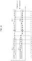
- FIG. 8 illustrates an example of determining a voltage group and a current group used for detecting an internal short by a battery control apparatus according to an exemplary embodiment of the present invention.
- the detecting unit 22 receives voltage values and current values measured at a plurality of measurement points t -23 to to from the measuring unit 21 and sets voltage groups VG1 and VG2 and current groups IG1 and IG2 to include some of the voltage values and the current values.
- the voltage values included in the voltage groups VG1 and VG2 may correspond to the voltage of each cell 100.
- the detecting unit 22 may set the voltage groups VG1 and VG2 for each cell 100.
- the voltage values included in the voltage groups VG1 and VG2 may correspond to the voltage of each battery sub module 11.
- the detecting unit 22 may set the voltage groups VG1 and VG2 for each battery sub module 11.
- the voltage values included in the voltage groups VG1 and VG2 may correspond to the voltage of the battery module 10.
- the current values included in the current groups IG1 and IG2 may correspond to the current which flows on each battery sub module 11.
- the detecting unit 22 may set the current groups IG1 and IG2 for each battery sub module 11.
- the current values included in the current groups IG1 and IG2 may correspond to the current which flows between the battery module 10 and the system terminals T+ and T-.
- the detecting unit 22 determines a first current group IG1 including current values measured at a plurality of measurement time points t -23 to t -14 and a second current group IG2 including current values measured at a plurality of measurement time points t -9 to to among the current values measured at the plurality of measurement time points t -23 to to by the measuring unit 21.
- the detecting unit 30 determines a first voltage group VG1 including voltage values measured at the plurality of measurement time points t -23 to t -14 and a second voltage group VG2 including voltage values measured at the plurality of measurement time points t -9 to to among the voltage values measured at the plurality of measurement time points t -23 to to by the measuring unit 21.
- the number of measurement time points corresponding to each of the voltage groups VG1 and VG2 and each of the current groups IG1 and IG2 is 10, but exemplary embodiments of the present invention are not limited thereto.
- Magnitudes of each of the voltage groups VG1 and VG2 and each of the current groups IG1 and IG2, that is, the numbers of voltage values and current values included in each of the voltage groups VG1 and VG2 and each of the current groups IG1 and IG2 may be proportional to sizes of memories allocated to each of the voltage groups VG1 and VG2 and each of the current groups IG1 and IG2.
- the detecting unit 22 may determine the current groups IG1 and IG2 (or voltage groups VG1 and VG2) so that a predetermined interval including at least one measurement time point t -13 to t -10 exists between the time period t -23 to t -14 corresponding to the first current group IG1 and the time period t -9 to to corresponding to the second current group IG2 (or between the time period t -23 to t -14 corresponding to the first voltage group VG1 and the time period t -9 to to corresponding to the second voltage group VG2).
- exemplary embodiments of the present invention are not limited thereto, and there may be no time gap between the time periods corresponding to the current groups IG1 and IG2 (or the voltage groups VG1 and VG2).
- the first voltage group VG1 may include voltage values measured a plurality of times during the first time period and the second voltage group VG2 may include voltage values measured a plurality of times during the second time period.
- the first current group IG1 includes current values measured a plurality of times during the first time period and the second current group IG2 includes current values measured a plurality of times during the second time period.
- the first time period and the second time period may partially overlap with each other, the time period may exist between two time periods or when the first time period is terminated, the second time period may be started. Further, the first time period may be earlier in time than the second time period. The lengths of the first and second time periods may be equal to or different from each other.
- FIG. 8 it is illustrated that a current measurement time point and a voltage measurement time point are equal to each other, but the current measurement time point and the voltage measurement time point may be different from each other. Further, in FIG. 8 , it is illustrated that the number of voltage values included in each of the voltage groups VG1 and VG2 and the number of current values included in each of the current groups IG1 and IG2 are equal to each other as an example, but the number of voltage values included in each of the voltage groups VG1 and VG2 and the number of current values included in each of the current groups IG1 and IG2 may be different from each other.
- the current values included in the first and second current groups IG1 and IG2 and the voltage values included in the first and second voltage groups VG1 and VG2 may be differently selected with time. That is, the detecting unit 22 may shift the time periods corresponding to the first and second current groups IG1 and IG2, respectively and the time periods corresponding to the first and second voltage groups VG1 and VG2, respectively whenever a new current value or a new voltage value is measured so that the second current group IG2 and the second voltage group VG2 include the current value and the voltage value (a current value and a voltage value measured most recently) at a current time point, respectively.
- Shifting the time period shifts the measurement time points corresponding to each of the current groups IG1 and IG2 or each of the voltage group VG1 and VG2 at least one by one, and as a result, the current values included in each of the current groups IG1 and IG2 or the voltage values included in each of the voltage groups VG1 and VG2 are changed.
- the time period corresponding to the second voltage group VG2 is t -10 to t -1
- the time period corresponding to the second voltage group VG2 is t -9 to to.
- the measuring unit 21, the detecting unit 22, or the control unit 23 may be performed by one or more central processing units (CPUs) or a processor implemented by other chipsets, microprocessors, etc.
- CPUs central processing units
- microprocessors etc.
- the first and second current groups IG1 and IG2 and the first and second voltage groups VG1 and VG2 correspond to the first and second current groups IG1 and IG2 and the first and second voltage groups VG1 and VG2 described with reference to FIG. 8 .
- FIG. 9 is a flowchart showing a method for detecting an internal short according to an exemplary embodiment of the present invention.
- the method for detecting the internal short in FIG. 9 may be performed by the battery control apparatus 20 described above.
- the method for detecting the internal short of FIG. 9 illustrates a method for detecting the internal short for one of the plurality of cells 100 constituting the battery module 10 and the same method for detecting the internal short may be applied even to the remaining cells 100.
- the voltage values included in the first voltage group VG1 and the second voltage group VG2 may correspond to a cell voltage of the cell 100 as an internal short detection target.
- the current values included in the first current group IG1 and the second current group IG2 may correspond to the current flowing on the battery sub module 11 including the corresponding cell 100.
- the current values included in the first current group IG1 and the second current group IG2 may correspond to the current flowing between the battery module 10 and the system terminals T+ and T-.
- the detecting unit 22 determines whether the state of the battery module 10 is the constant current (CC) charging by using the voltage values and the current values of the battery module 10, which are measured by the measuring unit 21 (S10). Specifically, when the charging current applied from the charging device (not illustrated) to the battery module 10 keeps a predetermined value and the voltage of the battery module 10 (or battery sub module 11) is measured to gradually increase, the detecting unit 22 determines that the state of the battery module 10 is in the constant current (CC) charging.
- the detecting unit 22 determines whether the first current group IG1 and the second current group IG2 corresponding to the cell 100 as the internal short detection target are stable (S11). For example, the detecting unit 22 determines that the first current group IG1 is stable when a change width (a difference between a maximum value and a minimum value of the current values included in the first current group IG1) of the current values included in the first current group IG1 is within a predetermined first range and determines that the first current group IG1 and the second current group IG2 are stable when a change width (a difference between the maximum value and the minimum value of the current values included in the second current group IG2) of the current values included in the second current group IG2 is within a predetermined first range.
- a change width a difference between a maximum value and a minimum value of the current values included in the first current group IG1
- the detecting unit 22 determines whether the first voltage group VG1 of the cell 100 as the internal short detection target is stable (S12). For example, the detecting unit 22 determines that the first voltage group VG1 is stable when the change width (the difference between the maximum value and the minimum value of the voltage values included in the first voltage group VG1) of the voltage values included in the first voltage group VG1 is within a predetermined second range.
- the detecting unit 22 determines whether a difference between a voltage average of the first voltage group VG1 and the voltage average of the second voltage group VG2 of the cell 100 as the internal short detection target, that is, a value acquired by subtracting the average of the voltage values included in the second voltage group VG2 from the average of the voltage values included in the first voltage group VG1 is equal to or larger than a first threshold Th1 (S13).
- the detecting unit 22 determines that the internal short occurs in the corresponding cell 100 (S14).
- the detecting unit 22 confirms that the battery module 10 is in the stable constant current (CC) charging state and then performs steps S11 and S12 described above in order to detect the internal short based on a voltage change.
- the first threshold Th1 may be a positive number. Referring to FIG. 4A , when the internal short occurs, the voltage of the cell 100 is instantaneously decreased, and as a result, even though the voltage of the cell 100 is then increased again, a state in which the voltage of the cell 100 is lower than the voltage before the internal short occurs is maintained during a predetermined period.
- a value acquired by subtracting the average of the voltage values included in the second voltage group VG2 from the average of the voltage values included in the first voltage group VG1 may be a real number larger than 0.
- FIG. 9 it is illustrated that the voltage averages of the first voltage group VG1 and the second voltage group VG2 corresponding to different time periods are compared with each other for the corresponding cell 100 in order to detect the internal short during the constant current (CC) charging as an example, but exemplary embodiments are not limited thereto.
- the detecting unit 22 compares the first voltage value and the second voltage value measured during different time periods during the constant current (CC) charging with each other to detect the internal short.
- the first voltage value may be one of the voltage values included in the first voltage group VG1 and the second voltage value may be one of the voltage values included in the second voltage group VG2, and the detecting unit 22 may determine that the internal short occurs when a value acquired by subtracting the second voltage value from the first voltage value is equal to or larger than a first threshold Th1.
- FIG. 10 is a flowchart showing a method for detecting an internal short according to another exemplary embodiment of the present invention.
- the method for detecting the internal short in FIG. 10 may be performed by the battery control apparatus 20 described above.
- the current values included in the first current group IG1 and the second current group IG2 may correspond to the current flowing on the battery sub module 11 as the internal short detection target.
- the voltage values included in the first voltage group VG1 and the second voltage group VG2 may correspond to the voltages at both ends of the battery sub module 11 as the internal short detection target.
- the voltage values included in the first voltage group VG1 and the second voltage group VG2 may correspond to the voltages at both ends of the battery module 10.
- the detecting unit 22 determines whether the state of the battery module 10 is the constant voltage (CVC) charging by using the voltage values and the current values of the battery module 10, which are measured by the measuring unit 21 (S20). Specifically, when the charging voltage of the battery module 10 is measured as a constant value and the charging current is measured to gradually decrease, the detecting unit 22 determines that the state of the battery module 10 is the constant voltage (CV) charging.
- the charging current used to determine whether the battery module 10 is in the CV charging may be a charging current measured in units of the battery sub module 11 as illustrated in FIG. 6A and the charging current measured for the entire battery module 10 as illustrated in FIG. 6B .
- the detecting unit 22 determines whether the first current group IG1 of the battery sub module 11 as the internal short detection target is stable (S21). For example, the detecting unit 22 determines whether the change width (the difference between the maximum value and the minimum value of the current values included in the first current group IG1) of the current values included in the first current group IG1 is within a predetermined third range and determines that the first current group IG1 is stable when the change width of the current values included in the first current group IG1 is within the predetermined third range.
- the change width the difference between the maximum value and the minimum value of the current values included in the first current group IG1
- the detecting unit 22 determines whether the first voltage group VG1 corresponding to the battery sub module 11 as the internal short detection target is stable (S22). For example, the detecting unit 22 determines whether the change width (the difference between the maximum value and the minimum value of the voltage values included in the first voltage group VG1) of the voltage values included in the first voltage group VG1 is within a predetermined fourth range and determines that the first voltage group VG1 is stable when the change width of the voltage values included in the first voltage group VG1 is within the predetermined fourth range.
- the detecting unit 22 determines whether a difference between the voltage average of the second voltage group VG2 and the voltage average of the first voltage group VG1 corresponding to the battery sub module 11 as the internal short detection target, that is, a value acquired by subtracting the average of the voltage values included in the first voltage group VG1 from the average of the voltage values included in the second voltage group VG2 is equal to or smaller than a second threshold Th2 (S23).
- the detecting unit 22 determines whether the difference between the current average of the second current group IG2 and the current average of the first current group IG1 of the battery sub module 11 as the internal short detection target, that is, a value acquired by subtracting the average of the current values included in the first current group IG1 from the average of the current values included in the second current group IG2 is equal to or more than a third threshold Th3 (S24).
- the detecting unit 22 determines that the internal short occurs in the corresponding battery sub module 11 (S25).
- step S23 is to distinguish a case where the charging current of the battery module 10 fluctuates due to fluctuation in charging voltage other than the internal short.
- step S23 it is illustrated as an example that the voltage averages of the first voltage group and the second voltage group corresponding to different time periods are compared with each other in order to detect the fluctuation in charging voltage, but exemplary embodiments are not limited thereto.
- the detecting unit 22 compares the first voltage value and the second voltage value measured during different time periods to check the fluctuation in charging voltage.
- the first and second voltage values are the instantaneous voltage values, and the first voltage value is one of the voltage values included in the first voltage group VG1 and the second voltage value is one of the voltage values included in the second voltage group VG2.
- step S23 may be changed to a step of determining whether the value acquired by subtracting the first voltage value from the second voltage value is equal to or less than the second threshold Th2.
- the third threshold Th3 may be a real number larger than 0.
- the charging current of the cell 100 instantly sharply increases, and as a result, the charging current of the battery sub module 11 including the corresponding cell 100 also increases instantaneously. As a result, even though the charging current of the corresponding battery sub module 11 then decreases again, the corresponding battery sub module 11 maintains a state in which the charging current is higher than the charging current before the internal short occurs during a predetermined period.
- the current average of the second current group IG2 measured after the occurrence of the internal short appears higher than the current average of the first current group IG1 measured before the internal short occurs, and as a result, a value acquired by subtracting the average of the current values included in the first current group IG1 from the average of the current values included in the second current group IG2 may be a real number larger than 0.
- the detecting unit 22 compares the first current value and the second current value measured during different time periods during the constant voltage (CV) charging with each other to detect the internal short.
- the first current value may be one of the current values included in the first current group IG1 and the second current value may be one of the current values included in the second current group IG2, and the detecting unit 22 may determine that the internal short occurs when a value acquired by subtracting the first current value from the second current value is equal to or larger than a third threshold Th3.
- FIG. 11 is a flowchart showing a method for detecting an internal short according to yet another exemplary embodiment of the present invention.
- the method for detecting the internal short in FIG. 11 may be performed by the battery control apparatus 20 described above.
- the voltage values included in the first voltage group VG1 and the second voltage group VG2 may correspond to a cell voltage of the cell 100 as an internal short detection target.
- the current values included in the first current group IG1 and the second current group IG2 may correspond to the current flowing on the battery sub module 11 including the cell 100 as the internal short detection target.
- the current values included in the first current group IG1 and the second current group IG2 may correspond to the current flowing between the battery module 10 and the system terminals T+ and T-.
- the detecting unit 22 determines whether a predetermined time elapsed from a last charging termination time point (S30). Specifically, the detecting unit 22 determines whether the predetermined time elapsed from a time point when the constant voltage (CV) charging described with reference to FIG. 9 is terminated or a time point when the constant current (CC) charging described with reference to FIG. 10 is terminated.
- the detecting unit 22 determines whether there is the charging current supplied to the battery module 10 (S31). Specifically, the detecting unit 22 may determine whether there is the charging current based on the current values measured between the battery module 10 and the system terminals T+ and T-after the predetermined time elapsed from the last charging termination time point of the battery module 10.
- the detecting unit 22 determines whether discharging current of the battery module 10 is equal to or smaller than a fourth threshold Th4 (S32). Specifically, the detecting unit 22 may determine whether the current value measured between the battery module 10 and the system terminals T+ and T- is equal to or smaller than the fourth threshold Th4 after the predetermined time elapsed from the last charging termination time point of the battery module 10. That is, the detecting unit 22 detects whether the battery module 10 is in the current open voltage state, that is, the state in which the load is not connected to the battery module 10 or the state in which a very low load is connected to the battery module 10 through step S32.
- the detecting unit 22 determines whether an absolute value of the difference between the current average of the first current group IG1 and the current average of the second current group IG2 corresponding to the cell 100 as the internal short detection target, that is, the difference in current average between the first current group IG1 and the second current group IG2 is equal to or smaller than a fifth threshold Th5 (S33).
- the detecting unit 22 determines whether the first voltage group VG1 of the cell 100 as the internal short detection target is stable (S34). For example, the detecting unit 22 determines that the first voltage group VG1 is stable when the change width (the difference between the maximum value and the minimum value) of the voltage values included in the first voltage group VG1 is within a predetermined fifth range.
- the detecting unit 22 determines whether the difference between the voltage average of the first voltage group VG1 and the voltage average of the second voltage group VG2 of the cell 100 as the internal short detection target, that is, a value acquired by subtracting the average of the voltage values included in the second voltage group VG2 from the average of the voltage values included in the first voltage group VG1 is equal to or larger than a sixth threshold Th6 (S35).
- the detecting unit 22 determines that the internal short occurs in the battery module 10 (S36).
- step S33 is to distinguish a case where the voltage of the battery module 10 fluctuates due to the current change of the battery module 10 other than the internal short in the open voltage state.
- step S33 it is illustrated as an example that the current averages of the first current group IG1 and the second current group IG2 corresponding to different time periods are compared with each other in order to check the current fluctuation of the battery module 10, but exemplary embodiments are not limited thereto.
- the detecting unit 22 compares the first current value and the second current value measured during different time periods to check the fluctuation in current.
- the first and second current values are the instantaneous current values, and the first current value is one of the current values included in the first current group IG1 and the second current value is one of the current values included in the second current group IG2.
- step S33 may be changed to a step of determining whether the difference between the first current and the second current is equal to or smaller than the fifth threshold Th5.
- the detecting unit 22 compares the first voltage value and the second voltage value measured during different time periods with each other to detect the internal short.
- the first voltage value may be one of the voltage values included in the first voltage group VG1 and the second voltage value may be one of the voltage values included in the second voltage group VG2, and the detecting unit 22 may determine that the internal short occurs when a value acquired by subtracting the second voltage value from the first voltage value is equal to or larger than the sixth threshold Th6.
- FIG. 12 is a flowchart showing a method for detecting an internal short according to still yet another exemplary embodiment of the present invention.
- the method for detecting the internal short in FIG. 12 may be performed by the battery control apparatus 20 described above.
- the method for detecting the internal short in FIG. 12 relates to a method for detecting the battery sub module 11 in which the internal short occurs among the plurality of battery sub modules 11 constituting the battery module 10.
- the current values included in the first current group IG1 and the second current group IG2 may correspond to the current flowing on the corresponding battery sub module 11.
- the voltage values included in the first voltage group VG1 and the second voltage group VG2 may correspond to the voltages of the corresponding battery sub module 11.
- the voltage values included in the first voltage group VG1 and the second voltage group VG2 may correspond to the voltages of the battery module 10.
- the detecting unit 22 determines whether the state of the battery module 10 is the constant voltage (CV) charging by using the voltage values and the current values of the battery module 10, which are measured by the measuring unit 21 (S40). Specifically, when the charging voltage of the battery module 10 is measured as a constant value and the charging current is measured to gradually decrease, the detecting unit 22 determines that the state of the battery module 10 is in the constant voltage (CV) charging.
- the charging current used to determine whether the battery module 10 is in the CV charging may be a charging current measured in units of the battery sub module 11 as illustrated in FIG. 6A and the charging current measured for the entire battery module 10 as illustrated in FIG. 6B .
- the detecting unit 22 determines whether the first current groups IG1 of the battery sub modules 11 are stable (S41). For example, the detecting unit 22 determines whether the change width (the difference between the maximum value and the minimum value of the current values included in the first current group IG1) of the current values included in the first current groups IG1 of the battery sub modules 11 is within a predetermined sixth range and determines that the first current group IG1 is stable when the change width of the current values included in the first current groups IG1 of the battery sub modules 11 is within the predetermined sixth range.
- the change width the difference between the maximum value and the minimum value of the current values included in the first current group IG1
- the detecting unit 22 determines whether the first voltage groups VG1 of the battery sub modules 11 are stable (S42). For example, the detecting unit 22 determines whether the change width (the difference between the maximum value and the minimum value of the voltage values included in the first voltage group VG1) of the voltage values included in the first voltage groups VG1 of the battery sub modules 11 is within a predetermined seventh range and determines that the first voltage groups VG1 are stable when the change width of the voltage values included in the first voltage group VG1 of the battery sub modules 11 is within the predetermined seventh range.
- the detecting unit 22 determines whether the difference between the voltage average of the second voltage group VG2 and the voltage average of the first voltage group VG1 for the battery sub modules 11 as the internal short detection target, that is, a value acquired by subtracting the average of the voltage values included in the first voltage group VG1 from the average of the voltage values included in the second voltage group VG2 is equal to or smaller than the seventh threshold Th7 (S43).
- the detecting unit 22 compares the current averages in the second current groups IG2 of the battery sub modules 11 when the difference between the voltage average of the second voltage group VG2 and the voltage average of the first voltage group of the battery sub modules 11 is equal to or smaller than the seventh threshold Th7. In addition, the detecting unit 22 checks whether a battery sub module 11 is detected, which has a larger current average in the second current group IG2 by an eighth threshold Th8 or larger than the remaining battery sub modules (S44).
- the detecting unit 22 determines that the internal short occurs in the corresponding battery sub module 11 when a battery sub module 11 is detected, which has a larger current average in the second current group IG2 by the eighth threshold Th8 or larger than the remaining battery sub modules 11 through step S44 (S45).
- step S43 is to distinguish a case where the charging current of the battery module 10 fluctuates due to fluctuation in charging voltage other than the internal short.
- step S43 it is illustrated as an example that the voltage averages of the first voltage group VG1 and the second voltage group VG2 corresponding to different time periods are compared with each other in order to detect the fluctuation in charging voltage in step S43, but exemplary embodiments are not limited thereto.
- the detecting unit 22 compares the first voltage value and the second voltage value measured during different time periods to check the fluctuation in charging voltage.
- the first and second voltage values are the instantaneous voltage values, and the first voltage value is one of the voltage values included in the first voltage group VG1 and the second voltage value is one of the voltage values included in the second voltage group VG2.
- step S43 may be changed to a step of determining whether the value acquired by subtracting the first voltage value from the second voltage value is equal to or smaller than the seventh threshold Th7.
- step S44 the current value of each battery sub module 11 may adopt the current value measured for each battery sub module 11 through the scheme illustrated in FIG. 6A . Further, in step S24, the current values of the respective battery sub modules 11 compared with each other may adopt the current average of the second current group IG2 or may be one of the current values included in the second current group IG2.
- the detecting unit 22 uses the difference between the maximum value and the minimum value among the current values included in the current group or the difference between the maximum value and the minimum value among the voltage values included in the voltage group in order to determine whether the current group or the voltage group is stable, but exemplary embodiments are not limited thereto.
- the detecting unit 22 may check the change width of each current group or each voltage group by using statistical parameters such as the standard deviation of the current values included in each current group or the voltage values included in each voltage group and determine whether each current group or each voltage group is stable based on the checked change width.
- the thresholds described in FIGS. 9 to 12 may also be all the real numbers larger than 0, but exemplary embodiments are not limited thereto.
- the battery control apparatus 20 may execute the protection functions for protecting the battery module 10 from the internal short.
- FIG. 13 is a flowchart showing a method for controlling a battery according to an exemplary embodiment of the present invention.
- the method for controlling a battery in FIG. 13 may be performed by the battery control apparatus 20 described above.
- the detecting unit 22 performs a detection operation of the internal short of the battery module 10 by using any one of the methods of FIGS. 9 to 12 described above (S50).
- the control unit 23 electrically separates the battery sub module 11 in which the internal short occurs from the system terminals T+ and T- (S52).
- the control unit 23 controls the switch 33 connected in series to the battery sub module 11 in which it is determined that the internal short occurs in the non-conductive state to electrically separate the battery sub module 11 determined that the internal short occurs from the system terminals T+ and T-.
- control unit 23 may use the remaining battery sub module 11 which normally operates.
- FIG. 14 is a flowchart showing a method for controlling a battery according to another exemplary embodiment of the present invention.
- the method for controlling a battery in FIG. 14 may be performed by the battery control apparatus 20 described above.
- the detecting unit 22 performs the detection operation of the internal short of the battery module 10 by using any one of the methods of FIGS. 9 to 12 described above (S60).
- the control unit 23 drops the voltage of the battery module 10 to a predetermined value or less by discharging the battery module 10 (S62).
- the control unit 23 may forcibly discharge the battery module 10 by connecting the battery module 10 to the external load 5 by controlling the main switch 32 in the conductive state when the occurrence of the internal short in the battery module 10 is detected by the detecting unit 22.
- the control unit 23 may forcibly discharge the battery module 10 by the discharging resistor 35 by controlling the switch 34 of the discharging circuit in the conductive state when the occurrence of the internal short in the battery module 10 is detected by the detecting unit 22.
- the control unit 23 discharges the battery module 10 by connecting the battery module 10 to the external load 5 or the discharge resistor 35 to forcibly reduce the voltage of the battery module 10, i.e., the voltage of the battery sub modules 11 to a predetermined value or less. Therefore, it is possible to prevent the normal cells 100 in the battery sub module 11 in which the internal short occurs from being overcharged.
- the electronic or electric devices and/or any other relevant devices or components according to embodiments of the present invention described herein may be implemented utilizing any suitable hardware, firmware (e.g. an application-specific integrated circuit), software, or a combination of software, firmware, and hardware.
- the various components of these devices may be formed on one integrated circuit (IC) chip or on separate IC chips.
- the various components of these devices may be implemented on a flexible printed circuit film, a tape carrier package (TCP), a printed circuit board (PCB), or formed on one substrate.
- the electrical connections or interconnections described herein may be realized by wires or conducting elements, e.g. on a PCB or another kind of circuit carrier.
- the conducting elements may comprise metallization, e.g. surface metallizations and/or pins, and/or may comprise conductive polymers or ceramics. Further electrical energy might be transmitted via wireless connections, e.g. using electromagnetic radiation and/or light.
- the various components of these devices may be a process or thread, running on one or more processors, in one or more computing devices, executing computer program instructions and interacting with other system components for performing the various functionalities described herein.
- the computer program instructions are stored in a memory which may be implemented in a computing device using a standard memory device, such as, for example, a random access memory (RAM).
- the computer program instructions may also be stored in other non-transitory computer readable media such as, for example, a CD-ROM, flash drive, or the like.
Abstract
a control unit (23) arranged to control the discharge switch (34) so that the voltage value of the battery module (10) is dropped to a predetermined value or less when the internal short occurs in the battery module (10).
Description
- The present invention relates to a battery system and a control method thereof.
- As the electric and electronic technology is developed, use of portable electronic products, which are small and light, and have various functions, is sharply increasing. A battery is generally used as a power supply device for an operation of a portable electronic product, and a rechargeable battery, which is charged and is re-usable, is mainly used.
- The rechargeable battery is a chargeable and dischargeable battery, unlike a primary battery that cannot be charged. The rechargeable battery is used in a portable small electronic device, such as a portable phone or a notebook computer, or is widely used as a power source for driving a motor of a power tool, a vehicle, and the like. An internal part of the rechargeable battery may be formed of a positive electrode, a negative electrode, a separation film, an electrolyte, and the like, and a case may be formed of a metal plate or a pouch.
- A rechargeable battery having high energy density may cause a problem in safety, such as thermal runaway, and particularly, the case where the positive electrode and the negative electrode inside the rechargeable battery are short-circuited, so that the rechargeable battery is overheated is a representative example. The internal short is caused from a loss of a function of the separation film, and examples thereof include deformation by an external impact, metallic foreign substances included in a manufacturing process, and the forming of dendrite of lithium or copper by an electrochemical reaction.
- In the related art, a technology of detecting a state of an internal short of a rechargeable battery in advance and preventing the internal short is developed. In the scheme in the related art, a check time of several tens of minute is required in the state where a voltage of the rechargeable battery is very stable. Accordingly, there is a disadvantage in that it is impossible to detect the internal short generated in the state where the rechargeable battery is continuously charged or discharged.
- The above information disclosed in this Background section is only for enhancement of understanding of the background of the invention and therefore The above information disclosed in this Background section is only for enhancement of understanding of the background of the invention, and therefore it may contain information that does not form the prior art that is already known in this country to a person of ordinary skill in the art.
- The above information disclosed in this Background section is only for enhancement of understanding of the background of the invention, and therefore it may contain information that does not form the prior art that is already known in this country to a person of ordinary skill in the art.
- The present invention has been made in an effort to provide a battery system and a control method thereof, which are capable of rapidly detecting an internal short in a battery module and protecting a battery system from the internal short.
- An exemplary embodiment of the present invention provides a battery system including: a battery module including a plurality of battery sub modules connected in parallel between system terminals; a plurality of switches connected in series to the plurality of battery sub modules, respectively; a measuring unit measuring voltage values of the battery module and/or cells included in the battery module and current values which flow on the battery modules; a detecting unit determining whether or not an internal short occurs in the plurality of battery sub modules by monitoring the voltage values or the current values; and a control unit controlling, when the internal short occurs in at least one battery sub module of the plurality of battery sub modules, at least one switch corresponding to the at least one battery sub module among the plurality of switches in a non-conductive state.
- In the battery system according to an exemplary embodiment, the detecting unit may determine each of a first voltage value in a first time period and a second voltage value in a second time period for the cells included in the plurality of battery sub modules based on the voltage values measured by the measuring unit and determine that the internal short occurs with respect to a cell in which a value acquired by subtracting the second voltage value from the first voltage value is equal to or larger than a first threshold among the cells, when the battery module is in constant current charging. Here, the second time period may include a time period after the first time period.
- In the battery system according to an exemplary embodiment, the detecting unit may perform detection of the internal short if a current change width in the first and second time periods of the plurality of battery sub modules is within a first range and a voltage change width in the first time period of the cells is within a second range, when the battery module is in the constant current charging.
- In the battery system according to an exemplary embodiment, the detecting unit may determine each of a first current value in the first time period and a second current value in the second time period for the plurality of battery sub modules based on the current values measured by the measuring unit and determine that the internal short occurs with respect to a battery sub module in which a value acquired by subtracting the first current value from the second current value is equal to or larger than a third threshold among the plurality of battery sub modules, when the battery module is in constant voltage charging. Here, the second time period may include a time period after the first time period.
- In the battery system according to an exemplary embodiment, the detecting unit may perform the detection of the internal short if the current change width and the voltage change width of the plurality of battery sub modules in the first time period are within a predetermined range and a difference between the first voltage value in the first time period and the second voltage value in the second time period of the plurality of battery sub modules is equal to or smaller than a second threshold, when the battery module is in the constant voltage charging.
- In the battery system according to an exemplary embodiment, the detecting unit may determine each of the first voltage value in the first time period and the second voltage value in the second time period for the cells included in the plurality of battery sub modules based on the voltage values measured by the measuring unit and determine that the internal short occurs with respect to a cell in which a value acquired by subtracting the second voltage value from the first voltage value is equal to or larger than a sixth threshold among the cells, after a predetermined time elapsed from a charging termination time point of the battery module. Here, the second time period may include a time period after the first time period.
- In the battery system according to an exemplary embodiment, the detecting unit may perform the detection of the internal short when there is no charging current supplied to the battery module during the first and second time periods and a discharging current of the battery module is equal to or smaller than a fourth threshold during the first and second time periods after the predetermined time elapsed from the charging termination time point of the battery module.
- In the battery system according to an exemplary embodiment, the detecting unit may perform the detection of the internal short when the difference between the first current value in the first time period and the second current value in the second time period of the plurality of battery sub modules is equal to or smaller than a fifth threshold and the voltage change width in the first time period of the cells is within a fifth range after the predetermined time elapsed from the charging termination time point of the battery module.
- In the battery system according to an exemplary embodiment, the detecting unit may compare the current values of the plurality of battery sub modules and determine that the internal short occurs with respect to a battery sub module having a larger current value by an eighth threshold or larger than the remaining battery sub modules among the plurality of battery sub modules, when the battery module is in the constant voltage charging. In this case, the detecting unit may perform the detection of the internal short if the current change width and the voltage change width of the plurality of battery sub modules in the first time period are within the predetermined range and the difference between the first voltage value in the first time period and the second voltage value in the second time period of the plurality of battery sub modules satisfies a seventh threshold or less, when the battery module is in the constant voltage charging. Here, the current values of the plurality of battery sub modules may be current values in the second time period, and the second time period may include a time period after the first time period.
- Another exemplary embodiment of the present invention provides a battery system including: a battery module connected between system terminals; a discharge circuit connected in parallel to the battery module between the system terminals and including a discharge switch and a discharge resistor connected to each other in series; a measuring unit measuring voltage values of the battery module and/or cells included in the battery module and current values which flow on the battery modules; a detecting unit determining whether or not an internal short occurs in the battery module by monitoring the voltage values or the current values; and a control unit controlling the discharge switch so that the voltage value of the battery module is dropped to a predetermined value or less when the internal short occurs in the battery module.
- In the battery system according to another exemplary embodiment, the detecting unit may determine each of a first voltage value in a first time period and a second voltage value in a second time period for the cells included in the plurality of battery modules based on the voltage values measured by the measuring unit and determine that the internal short occurs with respect to a cell in which a value acquired by subtracting the second voltage value from the first voltage value is equal to or larger than a first threshold among the cells, when the battery module is in a constant current charging. Here, the second time period may include a time period after the first time period.
- In the battery system according to another exemplary embodiment, the battery module may include a plurality of battery sub modules connected to each other in parallel and each including a plurality of cells.
- In the battery system according to another exemplary embodiment, the detecting unit may perform detection of the internal short if a current change width in the first and second time periods of the plurality of battery sub modules is within a first range and a voltage change width in the first time period of the plurality of cells is within a second range, when the battery module is in the constant current charging.
- In the battery system according to another exemplary embodiment, the detecting unit may determine each of a first current value in the first time period and a second current value in the second time period for the plurality of battery sub modules based on the current values measured by the measuring unit and determine that the internal short occurs with respect to a battery sub module in which a value acquired by subtracting the first current value from the second current value is equal to or larger than a third threshold among the plurality of battery sub modules, when the battery module is in constant voltage charging. Here, the second time period may include a time period after the first time period.
- In the battery system according to another exemplary embodiment, the detecting unit may perform the detection of the internal short if the current change width and the voltage change width of the plurality of battery sub modules in the first time period are within a predetermined range and a difference between the first voltage value in the first time period and the second voltage value in the second time period of the plurality of battery sub modules is equal to or smaller than a second threshold, when the battery module is in the constant voltage charging.
- In the battery system according to another exemplary embodiment, the detecting unit may determine each of the first voltage value in the first time period and the second voltage value in the second time period for the cells included in the plurality of battery sub modules based on the voltage values measured by the measuring unit and determine that the internal short occurs with respect to a cell in which a value acquired by subtracting the second voltage value from the first voltage value is equal to or larger than a sixth threshold among the cells, after a predetermined time elapsed from a charging termination time point of the battery module. Here, the second time period may include a time period after the first time period.
- In the battery system according to another exemplary embodiment, the detecting unit may perform the detection of the internal short when there is no charging current supplied to the battery module during the first and second time periods and a discharging current of the battery module is equal to or smaller than a fourth threshold during the first and second time periods after the predetermined time elapsed from the charging termination time point of the battery module after the predetermined time elapsed from the charging termination time point of the battery module.
- In the battery system according to another exemplary embodiment, the detecting unit may perform the detection of the internal short when the difference between the first current value in the first time period and the second current value in the second time period of the plurality of battery sub modules is equal to or smaller than a fifth threshold and the voltage change width in the first time period of the plurality of cells is within a fifth range after the predetermined time elapsed from the charging termination time point of the battery module.
- In the battery system according to another exemplary embodiment, the detecting unit may compare the current values of the plurality of battery sub modules and determine that the internal short occurs with respect to a battery sub module having a larger current value by an eighth threshold or larger than the remaining battery sub modules among the plurality of battery sub modules, when the battery module is in the constant voltage charging. In this case, the detecting unit may perform the detection of the internal short if the current change width and the voltage change width of the plurality of battery sub modules in the first time period are within the predetermined range and the difference between the first voltage value in the first time period and the second voltage value in the second time period of the plurality of battery sub modules satisfies a seventh threshold or less, when the battery module is in the constant voltage charging. Here, the current values of the plurality of battery sub modules may be current values in the second time period, and the second time period may include a time period after the first time period.
- Yet another exemplary embodiment of the present invention provides a control method of a battery system including a battery module including a plurality of battery sub modules connected in parallel between system terminals and a plurality of switches connected in series to the plurality of battery sub modules, respectively, including: measuring voltage values of the plurality of battery sub modules and/or cells included in the plurality of battery sub modules and current values which flow on the battery module; detecting occurrence of an internal short in the battery module by monitoring the voltage values or the current values; and controlling the plurality of switches so as to electrically separate at least one battery sub module in which the internal short occurs among the plurality of battery sub modules from the system terminals when the internal short occurs in the battery module.
- In the control method according to an exemplary embodiment, the detecting may include determining each of a first voltage value in a first time period and a second voltage value in a second time period with respect to the cells included in the plurality of battery sub modules based on the voltage values measured by the measuring unit when the battery module is in constant current charging, and determining that the internal short occurs with respect to a cell in which a value acquired by subtracting the second voltage value from the first voltage value is equal to or larger than a first threshold among the cells. Here, the second time period may include a time period after the first time period.
- In the control method according to an exemplary embodiment, the detecting may be performed if a current change width in the first and second time periods of the plurality of battery sub modules is within a first range and a voltage change width in the first time period of the cells is within a second range, when the battery module is in the constant current charging.
- In the control method according to an exemplary embodiment, the detecting may include determining each of a first current value in a first time period and a second current value in a second time period with respect to the plurality of battery sub modules based on the current values measured by the measuring unit when the battery module is in constant voltage charging, and determining that the internal short occurs in a battery sub module in which a value acquired by subtracting the first current value from the second current value among the plurality of battery sub modules is equal to or larger than a third threshold. Here, the second time period may include a time period after the first time period.
- In the control method according to an exemplary embodiment, the detecting may be performed if the current change width and the voltage change width of the plurality of battery sub modules in the first time period are within a predetermined range and a difference between the first voltage value in the first time period and the second voltage value in the second time period of the plurality of battery sub modules is equal to or smaller than a second threshold, when the battery module is in the constant voltage charging.
- In the control method according to an exemplary embodiment, the detecting may include determining each of a first voltage value in a first time period and a second voltage value in a second time period with respect to the cells included in the plurality of battery sub modules based on the voltage values measured by the measuring unit after a predetermined time elapsed from a charging termination time point of the battery module, and determining that the internal short occurs with respect to a cell in which a value acquired by subtracting the second voltage value from the first voltage value is equal to or larger than a sixth threshold value among the cells. Here, the second time period may include a time period after the first time period.
- In the control method according to an exemplary embodiment, the detecting may be performed when there is no charging current supplied to the battery module during the first and second time periods and a discharging current of the battery module is equal to or smaller than a fourth threshold during the first and second time periods after the predetermined time elapsed from the charging termination time point of the battery module.
- In the control method according to an exemplary embodiment, the detecting may be performed when the difference between the first current value in the first time period and the second current value in the second time period of the plurality of battery sub modules is equal to or smaller than a fifth threshold and the voltage change width in the first time period of the cells is within a fifth range after the predetermined time elapsed from the charging termination time point of the battery module.
- In the control method according to an exemplary embodiment, the detecting may include comparing current values of the plurality of battery sub modules when the battery module is in constant voltage charging, and determining that the internal short occurs in a battery sub module having a larger current value by an eighth threshold or larger than the remaining battery sub modules among the plurality of battery sub modules. In this case, the detecting may be performed if the current change width and the voltage change width of the plurality of battery sub modules in the first time period are within the predetermined range and the difference between the first voltage value in the first time period and the second voltage value in the second time period of the plurality of battery sub modules satisfies a seventh threshold or less, when the battery module is in the constant voltage charging. Here, the current values of the plurality of battery sub modules may be current values in the second time period, and the second time period may include a time period after the first time period.
- Still yet another exemplary embodiment of the present invention provides a control method of a battery system including a battery module connected between system terminals and a discharge circuit connected to the battery module in parallel between the system terminals, including: measuring voltage values of the battery module and/or cells included in the battery module and current values which flow on the battery modules; detecting occurrence of an internal short in the battery module by monitoring the voltage values or the current values; and operating a discharge circuit so that the voltage value of the battery module is dropped to a predetermined value or less when the internal short occurs in the battery module.
- In the control method according to another exemplary embodiment, the detecting may include determining each of a first voltage value in a first time period and a second voltage value in a second time period with respect to the cells included in the plurality of battery sub modules based on the voltage values measured by the measuring unit when the battery module is in constant current charging, and determining that the internal short occurs with respect to a cell in which a value acquired by subtracting the second voltage value from the first voltage value is equal to or larger than a first threshold among the cells. Here, the second time period may include a time period after the first time period.
- In the control method according to another exemplary embodiment, the battery module may include a plurality of battery sub modules connected to each other in parallel and each including a plurality of cells.
- In the control method according to another exemplary embodiment, the detecting may be performed if a current change width in the first and second time periods of the plurality of battery sub modules is within a first range and a voltage change width in the first time period of the cells is within a second range, when the battery module is in the constant current charging.
- In the control method according to another exemplary embodiment, the detecting may include determining each of a first current value in a first time period and a second current value in a second time period with respect to the plurality of battery sub modules based on the current values measured by the measuring unit when the battery module is in constant voltage charging, and determining that the internal short occurs in a battery sub module in which a value acquired by subtracting the first current value from the second current value among the plurality of battery sub modules is equal to or larger than a third threshold. Here, the second time period may include a time period after the first time period.
- In the control method according to another exemplary embodiment, the detecting may be performed if the current change width and the voltage change width of the plurality of battery sub modules in the first time period are within a predetermined range and a difference between the first voltage value in the first time period and the second voltage value in the second time period of the plurality of battery sub modules is equal to or smaller than a second threshold, when the battery module is in the constant voltage charging.
- In the control method according to another exemplary embodiment, the detecting may include determining each of a first voltage value in a first time period and a second voltage value in a second time period with respect to the cells included in the plurality of battery sub modules based on the voltage values measured by the measuring unit after a predetermined time elapsed from a charging termination time point of the battery module, and determining that the internal short occurs with respect to a cell in which a value acquired by subtracting the second voltage value from the first voltage value is equal to or larger than a sixth threshold value among the cells. Here, the second time period may include a time period after the first time period.
- In the control method according to another exemplary embodiment, the detecting may be performed when there is no charging current supplied to the battery module during the first and second time periods and a discharging current of the battery module is equal to or smaller than a fourth threshold during the first and second time periods after the predetermined time elapsed from the charging termination time point of the battery module.
- In the control method according to another exemplary embodiment, the detecting may be performed when the difference between the first current value in the first time period and the second current value in the second time period of the plurality of battery sub modules is equal to or smaller than a fifth threshold and the voltage change width in the first time period of the cells is within a fifth range after the predetermined time elapsed from the charging termination time point of the battery module.
- In the control method according to another exemplary embodiment, the detecting may include comparing current values of the plurality of battery sub modules when the battery module is in constant voltage charging, and determining that the internal short occurs in a battery sub module having a larger current value by an eighth threshold or larger than the remaining battery sub modules among the plurality of battery sub modules. In this case, the detecting may be performed if the current change width and the voltage change width of the plurality of battery sub modules in the first time period are within the predetermined range and the difference between the first voltage value in the first time period and the second voltage value in the second time period of the plurality of battery sub modules satisfies a seventh threshold or less, when the battery module is in the constant voltage charging. Here, the current values of the plurality of battery sub modules may be current values in the second time period, and the second time period may include a time period after the first time period.
- According to an aspect, there is provided a battery system comprising: a battery module including a plurality of battery sub modules connected in parallel between system terminals; a plurality of switches connected in series to the plurality of battery sub modules, respectively; a measuring unit arranged to measure voltage values of the battery module and/or cells included in the battery module and/or current values which flow on the battery modules; a detecting unit arranged to determine whether or not an internal short occurs in the plurality of battery sub modules by monitoring the voltage values or the current values; and a control unit arranged to control, when the internal short occurs in at least one battery sub module of the plurality of battery sub modules, at least one switch corresponding to the at least one battery sub module in a non-conductive state among the plurality of switches.
- In some embodiments, the detecting unit is arranged to determine each of a first voltage value in a first time period and a second voltage value in a second time period for the cells included in the plurality of battery sub modules based on the voltage values measured by the measuring unit and to determine that the internal short occurs with respect to a cell in which a value acquired by subtracting the second voltage value from the first voltage value is equal to or larger than a first threshold among the cells, when the battery module is in constant current charging, and the second time period includes a time period after the first time period.
- In some embodiments, the detecting unit is arranged to perform detection of the internal short if a current change width in the first and second time periods of the plurality of battery sub modules is within a first range and a voltage change width in the first time period of the cells is within a second range, when the battery module is in the constant current charging.
- In some embodiments, the detecting unit is arranged to determine each of a first current value in the first time period and a second current value in the second time period for the plurality of battery sub modules based on the current values measured by the measuring unit and to determine that the internal short occurs with respect to a battery sub module in which a value acquired by subtracting the first current value from the second current value is equal to or larger than a third threshold among the plurality of battery sub modules, when the battery module is in constant voltage charging, and the second time period includes a time period after the first time period.
- In some embodiments, the detecting unit is arranged to perform the detection of the internal short if the current change width and the voltage change width of the plurality of battery sub modules in the first time period are within a predetermined range and a difference between the first voltage value in the first time period and the second voltage value in the second time period of the plurality of battery sub modules is equal to or smaller than a second threshold, when the battery module is in the constant voltage charging.
- In some embodiments, the detecting unit is arranged to determine each of the first voltage value in the first time period and the second voltage value in the second time period for the cells included in the plurality of battery sub modules based on the voltage values measured by the measuring unit and to determine that the internal short occurs with respect to a cell in which a value acquired by subtracting the second voltage value from the first voltage value is equal to or larger than a sixth threshold among the cells, after a predetermined time elapsed from a charging termination time point of the battery module, and the second time period includes a time period after the first time period.
- In some embodiments, the detecting unit is arranged to perform the detection of the internal short when there is no charging current supplied to the battery module during the first and second time periods and a discharging current of the battery module is equal to or smaller than a fourth threshold during the first and second time periods after the predetermined time elapsed from the charging termination time point of the battery module.
- In some embodiments, the detecting unit is arranged to perform the detection of the internal short when the difference between the first current value in the first time period and the second current value in the second time period of the plurality of battery sub modules is equal to or smaller than a fifth threshold and the voltage change width in the first time period of the cells is within a fifth range after the predetermined time elapsed from the charging termination time point of the battery module.
- In some embodiments, the detecting unit is arranged to compare the current values of the plurality of battery sub modules and to determine that the internal short occurs with respect to a battery sub module having a larger current value by an eighth threshold or larger than the remaining battery sub modules among the plurality of battery sub modules, when the battery module is in the constant voltage charging.
- In some embodiments, the detecting unit is arranged to perform the detection of the internal short if the current change width and the voltage change width of the plurality of battery sub modules in the first time period are within the predetermined range and the difference between the first voltage value in the first time period and the second voltage value in the second time period of the plurality of battery sub modules satisfies a seventh threshold or less, when the battery module is in the constant voltage charging, the current values of the plurality of battery sub modules are current values in the second time period, and the second time period includes a time period after the first time period.
- According to an aspect, there is provided a control method of a battery system including a battery module including a plurality of battery sub modules connected in parallel between system terminals, the control method comprising: measuring voltage values of the plurality of battery sub modules and/or cells included in the plurality of battery sub modules and current values which flow on the battery module; detecting occurrence of an internal short in the battery module by monitoring the voltage values or the current values; and electrically separating at least one battery sub module in which the internal short occurs among the plurality of battery sub modules from the system terminals when the internal short occurs in the battery module.
- According to an aspect, there is provided a battery system as set out in
claim 1. Additional features of this aspect are set out inclaims 2 to 7. - According to an aspect, there is provided a control method of a battery system as set out in
claim 8. - According to exemplary embodiments of the present invention, there is an effect in that it is possible to rapidly detect an internal short in a battery module.
- Further, a battery system can be safely protected from the internal short.
-
-
FIG. 1 is a block diagram illustrating a configuration of a battery system according to an exemplary embodiment of the present invention. -
FIG. 2 illustrates an example of a battery module ofFIG. 1 . -
FIG. 3 illustrates an equivalent circuit of a secondary battery cell constituting the battery module ofFIG. 2 . -
FIGS. 4A to 4C are diagrams for describing changes in voltage and current depending on occurrence of an internal short of a secondary battery cell constituting the battery module ofFIG. 2 . -
FIG. 5 illustrates an example of measuring a voltage value of the battery module illustrated inFIG. 2 through a battery control apparatus according to an exemplary embodiment of the present invention. -
FIGS. 6A and6B illustrate examples of measuring a current value of the battery module illustrated inFIG. 2 through the battery control apparatus according to an exemplary embodiment of the present invention. -
FIGS. 7A and7B are diagrams for describing a protection operation of a battery module against an internal short in a battery control apparatus according to an exemplary embodiment of the present invention. -
FIG. 8 illustrates an example of determining a voltage group and a current group used for detecting an internal short by a battery control apparatus according to an exemplary embodiment of the present invention. -
FIG. 9 is a flowchart showing a method for detecting an internal short according to an exemplary embodiment of the present invention. -
FIG. 10 is a flowchart showing a method for detecting an internal short according to another exemplary embodiment of the present invention. -
FIG. 11 is a flowchart showing a method for detecting an internal short according to yet another exemplary embodiment of the present invention. -
FIG. 12 is a flowchart showing a method for detecting an internal short according to still yet another exemplary embodiment of the present invention. -
FIG. 13 is a flowchart showing a method for protecting a battery according to an exemplary embodiment of the present invention. -
FIG. 14 is a flowchart showing a method for protecting a battery according to another exemplary embodiment of the present invention. - Reference will now be made in detail to embodiments, examples of which are illustrated in the accompanying drawings. Effects and features of the exemplary embodiments, and implementation methods thereof will be described with reference to the accompanying drawings. In the drawings, like reference numerals denote like elements, and redundant descriptions are omitted. The present invention, however, may be embodied in various different forms, and should not be construed as being limited to only the illustrated embodiments herein. Rather, these embodiments are provided as examples so that this disclosure will be thorough and complete, and will fully convey the aspects and features of the present invention to those skilled in the art.
- Accordingly, processes, elements, and techniques that are not considered necessary to those having ordinary skill in the art for a complete understanding of the aspects and features of the present invention may not be described. In the drawings, the relative sizes of elements, layers, and regions may be exaggerated for clarity.
- As used herein, the term "and/or" includes any and all combinations of one or more of the associated listed items. Further, the use of "may" when describing embodiments of the present invention refers to "one or more embodiments of the present invention." In the following description of embodiments of the present invention, the terms of a singular form may include plural forms unless the context clearly indicates otherwise.
- It will be understood that although the terms "first" and "second" are used to describe various elements, these elements should not be limited by these terms. These terms are only used to distinguish one element from another element. For example, a first element may be named a second element and, similarly, a second element may be named a first element, without departing from the scope of the present invention. As used herein, the term "and/or" includes any and all combinations of one or more of the associated listed items. Expressions such as "at least one of," when preceding a list of elements, modify the entire list of elements and do not modify the individual elements of the list.
- Hereinafter, a battery system according to an exemplary embodiment of the present invention will be described in detail with reference to
FIGS. 1 to 3 . -
FIG. 1 is a diagram illustrating a configuration of a battery system according to an exemplary embodiment of the present invention. Further,FIG. 2 illustrates an example of a battery module ofFIG. 1 . - Referring to
FIG. 1 , abattery system 1 according to an exemplary embodiment of the present invention may include abattery module 10 and abattery control apparatus 20. - The
battery module 10 may include one or more secondary battery cells (hereinafter, referred to as a "cell") connected in series and/or in parallel. - Referring to
FIG. 2 as an example, thebattery module 10 includes a plurality ofbattery sub modules 11 connected in parallel between two system terminals T+ and T-. Further, eachbattery sub module 11 includes a plurality ofcell banks 13 connected to each other in series and eachcell bank 13 includes a plurality of cells, e.g., twocells 100 connected to each other in parallel.FIG. 2 illustrates an example of thebattery module 10 and a configuration of thebattery module 10 in embodiments is not limited thereto. For example, thebattery module 10 may be configured by a single cell. Further, for example, thebattery module 10 may be constituted only by a plurality of cells connected in series and a plurality of battery sub modules each constituted by the plurality of cells connected to each other in series may be configured to be connected to each other in parallel. - The
battery module 10 may be connected to an external charge device (not illustrated) or a load through the system terminals T+ and T- and charged by the charging device or discharged by the load. - The
battery module 10 is charged by one or more charging methods among constant current (CC) charging, in which charging is performed with a constant current from an initial stage to a completion stage of the charging, constant voltage (CV) charging, in which the charging is performed with a constant voltage from the initial stage to the completion stage of the charging, and CC-CV charging, in which the battery module is charged with the constant current at the initial stage of the charging and with the constant voltage at an end stage of the charging. -
FIG. 3 illustrates an equivalent circuit of a secondary battery cell constituting the battery module ofFIG. 2 . - Referring to
FIG. 3 , eachcell 100 constituting thebattery module 10 may include an internal resistance RB, and the internal resistance RB may have a resistance value of several mΩ to several hundreds of m. When the internal short occurs in thecell 100, an effect is generated, which is the same as an effect in which a switch S inside thecell 100 is conducted. When the switch S is conducted due to the occurrence of the internal short of thecell 100, short current Ishort flows on the short resistance Rs and thecell 100 is discharged. In this case, the short resistance Rs may have a resistance value of a broad range of several mΩ to several KΩ. -
FIGS. 4A to 4C are diagrams for describing changes in voltage and current depending on occurrence of an internal short of a secondary battery cell constituting the battery module ofFIG. 2 . - Referring to
FIG. 4A , when thebattery module 10 is charged by the CC charging, a charging current I supplied to thecell 100 has a predetermined value, and a voltage V of thecell 100 gradually increases. During the constant current (CC) charging, when the internal short Is occurs in thecell 100, there occurs a phenomenon in which the voltage V of thecell 100 sharply decreases and then increases again. Referring toFIG. 3 , the phenomenon occurs because equivalent resistance of thecell 100, that is, combined resistance of the internal resistance RB and the short resistance Rs of thecell 100, is momentarily changed due to the internal short of thecell 100. - Further, referring to
FIG. 4B , while thebattery module 100 is charged by the CV charging, the voltage V of thecell 100 has a predetermined value and the charging current I of thecell 100 gradually decreases. During the CV charging, when the internal short Is occurs in thecell 100, there occurs a phenomenon in which the charging current I of thecell 100 sharply increases and then decreases again. Referring toFIG. 3 , the phenomenon occurs because equivalent resistance of thecell 100, that is, the combined resistance of the internal resistance RB and the short resistance Rs of thecell 100, is momentarily changed due to the internal short of thecell 100. - Further, referring to
FIG. 4C , when the voltage of thebattery module 10 is in an open voltage state, for example, in the case where the load is not connected to thebattery module 10 or a very low load is connected to thebattery module 10, the voltage V of thecell 100 is constantly maintained for a predetermined time and then gradually decreases. In this case, when the internal short Is occurs in thecell 100, there occurs a phenomenon in which the voltage V of thecell 100 sharply decreases and then gradually decreases. Referring toFIG. 3 , the phenomenon occurs because equivalent resistance of thecell 100, that is, the combined resistance of the internal resistance RB and the short resistance Rs of thecell 100, is momentarily changed due to the internal short of thecell 100. - As illustrated in
FIGS. 4A to 4C , an internal short of thecell 100 causes a change in voltage or current of thecell 100, which may be measured even in thebattery module 10 constituted by the plurality ofcells 100 as illustrated inFIG. 2 . For example, when thebattery module 10 is CC-charged or thebattery module 10 is in the open voltage state, if the internal short occurs in aspecific cell 100, the voltage of abattery sub module 11 including thecorresponding cell 100 may also decrease. Further, for example, when the internal short occurs in thespecific cell 100 while thebattery module 10 is CV-charged, current which flows on thebattery sub module 11 including thecorresponding cell 100 or thebattery module 10 may also increase. Accordingly, in the exemplary embodiments of the present invention, the changes in voltage and/or current of thebattery module 10 are monitored to detect thecell 100 or thebattery sub module 11 in which the internal short occurs. - Referring back to
FIG. 1 , thebattery control apparatus 20 according to an embodiment of the present invention may detect the internal short of thebattery module 10 and execute a protection function for protecting thebattery module 10 from a dangerous situation caused by the internal short. To this end, thebattery control apparatus 20 may include a measuringunit 21, a detectingunit 22, and acontrol unit 23. - The measuring
unit 21 continuously measures a charging start time point and a charging termination time point of thebattery module 10 and a voltage, a current, and a temperature of thebattery module 10 and transfers the measured voltage values, current values, temperature values, charging start time point, charging termination time point, etc., to the detectingunit 22. The measuringunit 21 may discretely perform the measurement. A predetermined time period may exist between two measurement time points and a change of the time period may be changed. The measuringunit 21 may detect at least one of the voltage, the current, and the temperature at one measurement time point. - The voltage values of the
battery module 10 measured by the measuringunit 21 may include voltage values ofrespective cells 100 constituting thebattery module 10. Further, the voltage values of thebattery module 10 measured by the measuringunit 21 may include voltage values of respectivebattery sub modules 11 constituting thebattery module 10. In addition, the voltage values of thebattery module 10 measured by the measuringunit 21 may include voltage values of theentire battery module 10, i.e., a voltage value between the system terminals T+ and T-. -
FIG. 5 illustrates an example of measuring a voltage value of thebattery module 10 illustrated inFIG. 2 through the measuringunit 21. - Referring to
FIG. 5 , the measuringunit 21 may be electrically connected to both ends (or both ends of each cell bank 13) of eachcell 100 constituting thebattery module 10 and thus measure the voltage values of both ends of each cell 100 (or each cell bank 13) and/or thebattery sub module 11. - The current values of the
battery module 10 measured by the measuringunit 21 may include current values acquired by measuring charging current supplied from the charging device to theentire battery module 10 and/or discharging current supplied from thebattery module 10 to the load. Further, the current values of thebattery module 10 measured by the measuringunit 21 may include current values acquired by measuring the charging current supplied from the charging device for eachbattery sub module 11 constituting thebattery module 10 and/or discharging current supplied to the external load for eachbattery sub module 11. -
FIGS. 6A and6B illustrate examples of measuring a current value of thebattery module 10 illustrated inFIG. 2 through the measuringunit 21. - Referring to
FIG. 6A as an example, thebattery system 1 according to the exemplary embodiment may further includeshunt resistors 31 connected in series to each of thebattery sub modules 11. The charging current or discharging current flowing on eachbattery sub module 11 also flows even on thecorresponding shunt resistor 31. Accordingly, the measuringunit 21 may measure the charging current or the discharging current which flows on the correspondingbattery sub module 11 from a voltage drop caused by eachshunt resistor 31. - Referring to
FIG. 6B as an example, thebattery system 1 according to the exemplary embodiment may further includeshunt resistors 31 connected in series between any one of the system terminals T+ and T- and thebattery module 10. As a result, the current which flows between theentire battery module 10 and the charging device or between theentire battery module 10 and the load may flow on theshunt resistor 31 and the measuringunit 31 may measure the current which flows between theentire battery module 10 and the charging device or between theentire battery module 10 and the load from the voltage drop caused by theshunt resistor 31. - The detecting
unit 22 receives the voltage values, the current values, the temperature values, etc., measured for thebattery module 10 from the measuringunit 21 and stores the received voltage values, current values, temperature values, etc., in a memory (not illustrated). - Referring to
FIGS. 4A to 4C , a change aspect of the voltage or current of eachcell 100 depending on the internal short varies depending on whether thebattery module 10 is being charged and a charging scheme (CC charging and CV charging). Therefore, thebattery control apparatus 20 checks whether thecurrent battery module 10 is being charged and the charging scheme when thebattery module 10 is being charged in order to detect the internal short. That is, the detectingunit 22 determines whether thecurrent battery module 10 is any one of the CC charging state, the CV charging state, and the open voltage state (no load or low load state) by using the measured voltage values and current values of thebattery module 10. - Referring to
FIG. 4A , During the CC charging, when the internal short Is occurs in thecell 100 constituting thebattery module 10 during an interval of the CC charging, there occurs a phenomenon in which the voltage of thecorresponding cell 100 sharply decreases. Accordingly, the detectingunit 22 detects the occurrence of the internal short of eachcell 100 by monitoring the change in voltage of eachcell 100 constituting thebattery module 10 when thebattery module 10 is in the CC charging. - As an example, the detecting
unit 22 may determine a first voltage group and a second voltage group constituted by the voltage values measured in different time periods for eachcell 100 from the voltage values of eachcell 100, which are measured by the measuringunit 21 while thebattery module 10 is in the CC charging and detect the occurrence of the internal short in thecorresponding cell 100 by comparing the first voltage group and the second voltage group for thesame cell 100. That is, when the difference between an average of the voltage values included in the first voltage group and the average of the voltage values included in the second voltage group for thesame cell 100 is larger than or equal to a threshold, the detectingunit 22 may determine that the internal short occurs in thecorresponding cell 100. Here, each of the first voltage group and the second voltage group may include a plurality of voltage values measured for thecorresponding cell 100 during a predetermined period and the voltage values included in the first voltage group may be voltage values measured before the voltage values included in the second voltage group. A method for determining the first and second voltage groups will be described in detail with reference toFIG. 8 to be described below. - As another example, the detecting
unit 22 may select a first voltage value and a second voltage value measured during different time periods, respectively for eachcell 100 from the voltage values of eachcell 100, which are measured by the measuringunit 21 while thebattery module 10 is in the CC charging and detect the internal short of thecorresponding cell 100 by comparing the first voltage value and the second voltage value for thesame cell 100. That is, when the difference between the first voltage value and the second voltage value is larger than or equal to a threshold for thesame cell 100, the detectingunit 22 may determine that the internal short occurs in thecorresponding cell 100. Here, the first and second voltage values are instantaneous voltage values and the first voltage value may be a voltage value measured before the second voltage value. - Referring to
FIG. 4B , when the internal short Is occurs in thecell 100 constituting thebattery module 10 during the interval of the CV charging, the charging current I of thecell 100 in which the internal short occurs instantaneously sharply increases. Accordingly, the detectingunit 22 detects the occurrence of the internal short of thebattery module 10 by monitoring the change in current of thebattery module 10 when thebattery module 10 is in the CV charging. - As an example, the detecting
unit 22 may determine a first current group and a second current group constituted by the current values measured in different time periods for eachbattery sub module 11 from the current values (see the current measuring scheme ofFIG. 6A ) measured for eachbattery sub module 11 by the measuringunit 21 while thebattery module 10 is in the CV charging and detect the internal short of the correspondingbattery sub module 11 by comparing the first current group and the second current group for the samebattery sub module 11. That is, when the difference between the average of the current values included in the first current group and the average of the current values included in the second current group for the samebattery sub module 11 is larger than or equal to a threshold, the detectingunit 22 may determine that the internal short occurs in thecell 100 included in the correspondingbattery sub module 11. Here, each of the first current group and the second current group may include a plurality of current values measured for the correspondingbattery sub module 11 during a predetermined period and the current values included in the first current group may be current values measured before the current values included in the second current group. A method for determining the first and second current groups will be described in detail with reference toFIG. 8 to be described below. - As another example, the detecting
unit 22 may select the first current value and the second current value measured in different time periods, respectively for eachbattery sub module 11 from the current values (see the current measuring scheme ofFIG. 6A ) measured for eachbattery sub module 11 by the measuringunit 21 while thebattery module 10 is in the CV charging and detect the internal short of the correspondingbattery sub module 11 by comparing the first current value and the second current value for the samebattery sub module 11. That is, when the difference between the first current value and the second current value is larger than or equal to a threshold for the samebattery sub module 11, the detectingunit 22 may determine that the internal short occurs in thecell 100 included in the correspondingbattery sub module 11. Here, the first and second current values are instantaneous current values and the first current value may be a current value measured before the second current value. - As another example, the detecting
unit 22 may compare the current values (see the current measuring scheme ofFIG. 6A ) of thebattery sub modules 11, which are measured by the measuringunit 21 while thebattery module 10 is in the CV charging and determine that the internal short occurs for thebattery sub module 11 having a larger current value by a predetermined value or larger than anotherbattery sub module 11. - As yet another example, the detecting
unit 22 may determine the first current group and the second current group constituted by the current values measured during different time periods from the current values (see the current measuring scheme ofFIG. 6B ) measured for thebattery module 10 by the measuringunit 21 while thebattery module 10 is in the CV charging and detect the internal short in thebattery module 10 by comparing the first current group and the second current group with each other. That is, when the difference between the average of the current values included in the first current group and the average of the current values included in the second current group is larger than or equal to a threshold, the detectingunit 22 may determine that the internal short occurs in thecell 100 included in thebattery module 10. Here, each of the first current group and the second current group may include a plurality of current values measured for thebattery module 10 during a predetermined period and the current values included in the first current group may be current values measured before the current values included in the second current group. A method for determining the first and second current groups will be described in detail with reference toFIG. 8 to be described below. - As yet another example, the detecting
unit 22 may select the first current value and the second current value measured during different time periods, respectively for eachbattery sub module 11 from the current values (see the current measuring scheme ofFIG. 6B ) measured for thebattery module 10 by the measuringunit 21 while thebattery module 10 is in the CV charging and detect the internal short in thebattery module 10 by comparing the first current value and the second current value with each other. That is, when the difference between the first current value and the second current value is larger than or equal to a threshold, the detectingunit 22 may determine that the internal short occurs in thecell 100 included in thebattery module 10. Here, the first and second current values are instantaneous current values of thebattery module 10 and the first current value may be a current value measured before the second current value. - In general, due to problems in cost and installation space, the current which flows on the
battery module 10 configured by connecting a plurality ofcells 100 in series and/or in parallel is measured in units of thebattery sub module 11 as illustrated inFIG. 6A or measured in units of thebattery module 10 as illustrated inFIG. 6B . Further, as illustrated inFIG. 2 , when the cells 100 (or cell banks 13) included in eachbattery sub module 11 are connected to each other in series, the same current flows on the cells 100 (or cell banks 13) included in the samebattery sub module 11, and as a result, there is a problem in that it is difficult to determine whether the internal short occurs in units of the cell 100 (or cell bank 13) even though the current which flows on each cell 100 (or cell bank 13) is measured. Therefore, as described above, the detectingunit 22 may determine whether the internal short occurs by monitoring the current which flows on eachbattery sub module 11 or the current which flows on thebattery module 10. In the former case, the detectingunit 22 may specify thebattery sub module 11 including thecell 100 in which the internal short occurs. - Referring to
FIG. 4C , when charging of thebattery module 10 is terminated and thebattery module 10 is in the open voltage state (for example, a state where no load is connected to thebattery module 10 or a state where a very low load is connected), the voltage of eachcell 100 is kept constant for a predetermined time and then gradually decreased and when the internal short occurs, the voltage of thecorresponding cell 100 is sharply decreased. Accordingly, the detectingunit 22 detects the occurrence of the internal short of thebattery module 10 by monitoring the change in voltage of eachcell 100 when the charging of thebattery module 10 is terminated and thebattery module 10 is in the current open voltage state. - As an example, the detecting
unit 22 may determine a first voltage group and a second voltage group constituted by the voltage values measured in different time periods for eachcell 100 from the voltage values of eachcell 100, which are measured by the measuringunit 21 while thebattery module 10 is in the open voltage state and detect the internal short of thecorresponding cell 100 by comparing the first voltage group and the second voltage group for thesame cell 100. That is, when the difference between an average of the voltage values included in the first voltage group and the average of the voltage values included in the second voltage group for thesame cell 100 is larger than or equal to a threshold, the detectingunit 22 may determine that the internal short occurs in thecorresponding cell 100. Here, each of the first voltage group and the second voltage group may include a plurality of voltage values measured for thecorresponding cell 100 during a predetermined period and the voltage values included in the first voltage group may be voltage values measured before the voltage values included in the second voltage group. A method for determining the first and second voltage groups will be described in detail with reference toFIG. 4 to be described below. - As another example, the detecting
unit 22 may select a first voltage value and a second voltage value measured during different time periods, respectively for eachcell 100 from the voltage values of eachcell 100, which are measured by the measuringunit 21 while thebattery module 10 is in the open voltage state and detect the internal short of thecorresponding cell 100 by comparing the first voltage value and the second voltage value for thesame cell 100. That is, when the difference between the first voltage value and the second voltage value is larger than or equal to a threshold for thesame cell 100, the detectingunit 22 may determine that the internal short occurs in thecorresponding cell 100. Here, the first and second voltage values are instantaneous voltage values and the first voltage value may be a voltage value measured before the second voltage value. - Meanwhile, when the
battery module 10 is in the open voltage state, voltage values used for determining the internal short may be voltage values measured after a predetermined time elapsed from a charging termination time point of thebattery module 10. Here, the predetermined time may mean a time until the internal short may be determined after charging termination and when the internal short is determined by using voltage values measured before the predetermined time, determination accuracy may be degraded. - When the detecting
unit 22 detects the occurrence of the internal short of thebattery module 10 by using the aforementioned schemes, the detectingunit 22 generates a detection signal Ds including the state of thebattery module 10 and whether the internal short Is occurs. A specific process of detecting the internal short of thebattery module 10 by the detectingunit 22 will be described in detail with reference toFIGS. 9 to 12 to be described below. - As illustrated in
FIG. 2 , when the internal short occurs in thebattery module 10 configured by connecting the plurality ofbattery sub modules 11 in parallel, the voltage of thebattery sub module 11 including thecell 100 in which the internal short occurs instantaneously decreases, and as a result, a current for compensating for the voltage drop in thebattery sub module 11 in which the internal short occurs may flow from the adjacentbattery sub modules 11. Therefore, a situation may occur in which thecells 100 in thebattery sub module 11 in which the internal short occurs are charged with the flowing current andnormal cells 100 in thebattery sub module 11 in which the internal short occurs are overcharged. - Accordingly, the
control unit 23 may execute protection operations for protecting thebattery module 10 from the dangerous situation caused by the internal short, based on the detection signal Ds generated by the detectingunit 22. - Hereinafter, protection operations for protecting the
batter module 10 from the internal short by thebattery control apparatus 20 according to the exemplary embodiment of the present invention will be described with reference toFIGS. 7A and7B . -
FIGS. 7A and7B are diagrams for describing a protection operation of abattery module 10 for an internal short of abattery control apparatus 20. - Referring to
FIG. 7A , thebattery system 1 according to the exemplary embodiment may further include amain switch 32 connected in series between any one of the system terminals T+ and T- and thebattery module 10. Thebattery system 1 may further include aswitch 33 connected in series to each of thebattery sub modules 11. Here, themain switch 32 and theswitch 33 may adopt various types of switching elements driven by electrical control signals, such as a relay, a contactor semiconductor switch (transistor, etc.), a short circuit protection (SCP), etc. - The
control unit 23 may interrupt the connection of the external charging device (not illustrated) or the load (not illustrated) connected to thebattery module 10 by controlling themain switch 32 in the non-conductive state when the detection signal Ds indicating the occurrence of the internal short of thebattery module 10 is generated by the detectingunit 22. - Further, when the
control unit 23 may identify thebattery sub module 11 including the cell in which the internal short occurs among thebattery sub modules 11, thecontrol unit 23 may control theswitch 33 connected to the correspondingbattery sub module 11 in a non-conductive state instead of themain switch 32. In this case, when connection of only thebattery sub module 11 in which the internal short occurs is interrupted, it is possible to use the remainingbattery sub modules 11 which normally operate. - Referring to
FIG. 7B , thebattery system 1 according to the exemplary embodiment may further include amain switch 32 connected in series between any one of the system terminals T+ and T- and thebattery module 10 or a discharge circuit connected in parallel to thebattery module 10 between the system terminals T+ and T-, i.e., aswitch 34 and adischarge resistor 35. Here, themain switch 32 and theswitch 34 may adopt various types of switching elements driven by electrical control signals, such as a relay, a contactor semiconductor switch (transistor, etc.), etc. - The
control unit 23 may connect thebattery module 10 to theexternal load 5 by controlling themain switch 32 in a conductive state when the detection signal Ds indicating the occurrence of the internal short of thebattery module 10 is generated by the detectingunit 22. - Further, the
control unit 23 may control thebattery module 10 to be discharged by thedischarge resistor 35 by controlling theswitch 34 in the conductive state when the detection signal Ds indicating the occurrence of the internal short in thebattery module 10 is generated by the detectingunit 22. - As such, when the internal short occurs in the
battery module 10, thecontrol unit 23 discharges thebattery module 10 by connecting thebattery module 10 to theexternal load 5 or thedischarge resistor 35 to forcibly reduce the voltage of thebattery module 10, i.e., the voltage of thebattery sub modules 11 to a predetermined value or less. Therefore, it is possible to prevent thenormal cells 100 in thebattery sub module 11 in which the internal short occurs from being overcharged. - Meanwhile, when the detection signal Ds indicating the occurrence of the internal short of the
battery module 10 is generated by the detectingunit 22, thecontrol unit 23 may transfer a notification signal for notifying the occurrence of the internal short of thebattery module 10 to a higher system. -
FIG. 8 illustrates an example of determining a voltage group and a current group used for detecting an internal short by a battery control apparatus according to an exemplary embodiment of the present invention. - Referring to
FIG. 8 , the detectingunit 22 receives voltage values and current values measured at a plurality of measurement points t-23 to to from the measuringunit 21 and sets voltage groups VG1 and VG2 and current groups IG1 and IG2 to include some of the voltage values and the current values. - The voltage values included in the voltage groups VG1 and VG2 may correspond to the voltage of each
cell 100. In this case, the detectingunit 22 may set the voltage groups VG1 and VG2 for eachcell 100. - The voltage values included in the voltage groups VG1 and VG2 may correspond to the voltage of each
battery sub module 11. In this case, the detectingunit 22 may set the voltage groups VG1 and VG2 for eachbattery sub module 11. - The voltage values included in the voltage groups VG1 and VG2 may correspond to the voltage of the
battery module 10. - The current values included in the current groups IG1 and IG2 may correspond to the current which flows on each
battery sub module 11. In this case, the detectingunit 22 may set the current groups IG1 and IG2 for eachbattery sub module 11. - The current values included in the current groups IG1 and IG2 may correspond to the current which flows between the
battery module 10 and the system terminals T+ and T-. - In
FIG. 8 , to represents a current measurement time point, i.e., a most recent measurement time point and t-23 represents a measurement time point measured earliest. Specifically, as illustrated inFIG. 8 , the detectingunit 22 determines a first current group IG1 including current values measured at a plurality of measurement time points t-23 to t-14 and a second current group IG2 including current values measured at a plurality of measurement time points t-9 to to among the current values measured at the plurality of measurement time points t-23 to to by the measuringunit 21. Further, the detectingunit 30 determines a first voltage group VG1 including voltage values measured at the plurality of measurement time points t-23 to t-14 and a second voltage group VG2 including voltage values measured at the plurality of measurement time points t-9 to to among the voltage values measured at the plurality of measurement time points t-23 to to by the measuringunit 21. For convenience of description, it is described that the number of measurement time points corresponding to each of the voltage groups VG1 and VG2 and each of the current groups IG1 and IG2 is 10, but exemplary embodiments of the present invention are not limited thereto. Magnitudes of each of the voltage groups VG1 and VG2 and each of the current groups IG1 and IG2, that is, the numbers of voltage values and current values included in each of the voltage groups VG1 and VG2 and each of the current groups IG1 and IG2 may be proportional to sizes of memories allocated to each of the voltage groups VG1 and VG2 and each of the current groups IG1 and IG2. - Referring to
FIGS. 4A to 4C , when the internal short occurs in thecell 100, the current (or voltage) is unstable during a predetermined period. Accordingly, in order to make a situation of comparing current (or voltage) of both time periods which is relatively stable with a period in which the current (or voltage) is unstable due to the occurrence of the internal short when the internal short occurs, as illustrated inFIG. 8 , the detectingunit 22 may determine the current groups IG1 and IG2 (or voltage groups VG1 and VG2) so that a predetermined interval including at least one measurement time point t-13 to t-10 exists between the time period t-23 to t-14 corresponding to the first current group IG1 and the time period t-9 to to corresponding to the second current group IG2 (or between the time period t-23 to t-14 corresponding to the first voltage group VG1 and the time period t-9 to to corresponding to the second voltage group VG2). However, exemplary embodiments of the present invention are not limited thereto, and there may be no time gap between the time periods corresponding to the current groups IG1 and IG2 (or the voltage groups VG1 and VG2). - That is, the first voltage group VG1 may include voltage values measured a plurality of times during the first time period and the second voltage group VG2 may include voltage values measured a plurality of times during the second time period. Similarly, the first current group IG1 includes current values measured a plurality of times during the first time period and the second current group IG2 includes current values measured a plurality of times during the second time period. The first time period and the second time period may partially overlap with each other, the time period may exist between two time periods or when the first time period is terminated, the second time period may be started. Further, the first time period may be earlier in time than the second time period. The lengths of the first and second time periods may be equal to or different from each other.
- In
FIG. 8 , it is illustrated that a current measurement time point and a voltage measurement time point are equal to each other, but the current measurement time point and the voltage measurement time point may be different from each other. Further, inFIG. 8 , it is illustrated that the number of voltage values included in each of the voltage groups VG1 and VG2 and the number of current values included in each of the current groups IG1 and IG2 are equal to each other as an example, but the number of voltage values included in each of the voltage groups VG1 and VG2 and the number of current values included in each of the current groups IG1 and IG2 may be different from each other. - In
FIG. 8 , the current values included in the first and second current groups IG1 and IG2 and the voltage values included in the first and second voltage groups VG1 and VG2 may be differently selected with time. That is, the detectingunit 22 may shift the time periods corresponding to the first and second current groups IG1 and IG2, respectively and the time periods corresponding to the first and second voltage groups VG1 and VG2, respectively whenever a new current value or a new voltage value is measured so that the second current group IG2 and the second voltage group VG2 include the current value and the voltage value (a current value and a voltage value measured most recently) at a current time point, respectively. Shifting the time period shifts the measurement time points corresponding to each of the current groups IG1 and IG2 or each of the voltage group VG1 and VG2 at least one by one, and as a result, the current values included in each of the current groups IG1 and IG2 or the voltage values included in each of the voltage groups VG1 and VG2 are changed. For example, at time t-1, the time period corresponding to the second voltage group VG2 is t-10 to t-1, and at time to, the time period corresponding to the second voltage group VG2 is t-9 to to. - In the
battery control apparatus 20 described above, the measuringunit 21, the detectingunit 22, or thecontrol unit 23 may be performed by one or more central processing units (CPUs) or a processor implemented by other chipsets, microprocessors, etc. - Hereinafter, a method for detecting an internal short of a
battery module 10 according to exemplary embodiments of the present invention will be described with reference toFIGS. 9 to 12 . In the following description, the first and second current groups IG1 and IG2 and the first and second voltage groups VG1 and VG2 correspond to the first and second current groups IG1 and IG2 and the first and second voltage groups VG1 and VG2 described with reference toFIG. 8 . -
FIG. 9 is a flowchart showing a method for detecting an internal short according to an exemplary embodiment of the present invention. The method for detecting the internal short inFIG. 9 may be performed by thebattery control apparatus 20 described above. - Meanwhile, the method for detecting the internal short of
FIG. 9 illustrates a method for detecting the internal short for one of the plurality ofcells 100 constituting thebattery module 10 and the same method for detecting the internal short may be applied even to the remainingcells 100. InFIG. 9 , the voltage values included in the first voltage group VG1 and the second voltage group VG2 may correspond to a cell voltage of thecell 100 as an internal short detection target. In addition, the current values included in the first current group IG1 and the second current group IG2 may correspond to the current flowing on thebattery sub module 11 including thecorresponding cell 100. In addition, the current values included in the first current group IG1 and the second current group IG2 may correspond to the current flowing between thebattery module 10 and the system terminals T+ and T-. - Referring to
FIG. 9 , the detectingunit 22 determines whether the state of thebattery module 10 is the constant current (CC) charging by using the voltage values and the current values of thebattery module 10, which are measured by the measuring unit 21 (S10). Specifically, when the charging current applied from the charging device (not illustrated) to thebattery module 10 keeps a predetermined value and the voltage of the battery module 10 (or battery sub module 11) is measured to gradually increase, the detectingunit 22 determines that the state of thebattery module 10 is in the constant current (CC) charging. - When it is determined that the
battery module 10 is in the constant current (CC) charging, the detectingunit 22 determines whether the first current group IG1 and the second current group IG2 corresponding to thecell 100 as the internal short detection target are stable (S11). For example, the detectingunit 22 determines that the first current group IG1 is stable when a change width (a difference between a maximum value and a minimum value of the current values included in the first current group IG1) of the current values included in the first current group IG1 is within a predetermined first range and determines that the first current group IG1 and the second current group IG2 are stable when a change width (a difference between the maximum value and the minimum value of the current values included in the second current group IG2) of the current values included in the second current group IG2 is within a predetermined first range. - When it is determined that the first current group IG1 and the second current group IG2 are stable through step S11, the detecting
unit 22 determines whether the first voltage group VG1 of thecell 100 as the internal short detection target is stable (S12). For example, the detectingunit 22 determines that the first voltage group VG1 is stable when the change width (the difference between the maximum value and the minimum value of the voltage values included in the first voltage group VG1) of the voltage values included in the first voltage group VG1 is within a predetermined second range. - When it is determined that the first voltage group VG1 is stable through step S12, the detecting
unit 22 determines whether a difference between a voltage average of the first voltage group VG1 and the voltage average of the second voltage group VG2 of thecell 100 as the internal short detection target, that is, a value acquired by subtracting the average of the voltage values included in the second voltage group VG2 from the average of the voltage values included in the first voltage group VG1 is equal to or larger than a first threshold Th1 (S13). - When the difference between the voltage average of the second voltage group VG2 and the voltage average of the first voltage group VG1 is equal to or larger than the first threshold Th1, the detecting
unit 22 determines that the internal short occurs in the corresponding cell 100 (S14). - A situation in which the current or voltage of the
battery module 10 is swung due to factors (the apparatus is used during charging, etc.) other than the internal short while thebattery module 10 is in the constant current (CC) charging may occur and when the internal short is detected in such a situation, a detection error may occur. Accordingly, the detectingunit 22 confirms that thebattery module 10 is in the stable constant current (CC) charging state and then performs steps S11 and S12 described above in order to detect the internal short based on a voltage change. - In step S13, the first threshold Th1 may be a positive number. Referring to
FIG. 4A , when the internal short occurs, the voltage of thecell 100 is instantaneously decreased, and as a result, even though the voltage of thecell 100 is then increased again, a state in which the voltage of thecell 100 is lower than the voltage before the internal short occurs is maintained during a predetermined period. That is, when the internal short occurs, the voltage average of the second voltage group VG2 measured after the occurrence of the internal short appears lower than the voltage average of the first voltage group VG1 measured before the internal short occurs, and as a result, a value acquired by subtracting the average of the voltage values included in the second voltage group VG2 from the average of the voltage values included in the first voltage group VG1 may be a real number larger than 0. - Meanwhile, in
FIG. 9 , it is illustrated that the voltage averages of the first voltage group VG1 and the second voltage group VG2 corresponding to different time periods are compared with each other for thecorresponding cell 100 in order to detect the internal short during the constant current (CC) charging as an example, but exemplary embodiments are not limited thereto. For example, the detectingunit 22 compares the first voltage value and the second voltage value measured during different time periods during the constant current (CC) charging with each other to detect the internal short. Here, the first voltage value may be one of the voltage values included in the first voltage group VG1 and the second voltage value may be one of the voltage values included in the second voltage group VG2, and the detectingunit 22 may determine that the internal short occurs when a value acquired by subtracting the second voltage value from the first voltage value is equal to or larger than a first threshold Th1. -
FIG. 10 is a flowchart showing a method for detecting an internal short according to another exemplary embodiment of the present invention. The method for detecting the internal short inFIG. 10 may be performed by thebattery control apparatus 20 described above. - Meanwhile, as the method for detecting the internal short of
FIG. 10 , a method for detecting the internal short for one of the plurality ofbattery sub modules 11 constituting thebattery module 10 is illustrated and the same method for detecting the internal short may be applied even to the remainingbattery sub modules 11. InFIG. 10 , the current values included in the first current group IG1 and the second current group IG2 may correspond to the current flowing on thebattery sub module 11 as the internal short detection target. Further, the voltage values included in the first voltage group VG1 and the second voltage group VG2 may correspond to the voltages at both ends of thebattery sub module 11 as the internal short detection target. In addition, the voltage values included in the first voltage group VG1 and the second voltage group VG2 may correspond to the voltages at both ends of thebattery module 10. - Referring to
FIG. 10 , the detectingunit 22 determines whether the state of thebattery module 10 is the constant voltage (CVC) charging by using the voltage values and the current values of thebattery module 10, which are measured by the measuring unit 21 (S20). Specifically, when the charging voltage of thebattery module 10 is measured as a constant value and the charging current is measured to gradually decrease, the detectingunit 22 determines that the state of thebattery module 10 is the constant voltage (CV) charging. Here, the charging current used to determine whether thebattery module 10 is in the CV charging may be a charging current measured in units of thebattery sub module 11 as illustrated inFIG. 6A and the charging current measured for theentire battery module 10 as illustrated inFIG. 6B . - When the
battery module 10 is in the constant voltage (CV) charging, the detectingunit 22 determines whether the first current group IG1 of thebattery sub module 11 as the internal short detection target is stable (S21). For example, the detectingunit 22 determines whether the change width (the difference between the maximum value and the minimum value of the current values included in the first current group IG1) of the current values included in the first current group IG1 is within a predetermined third range and determines that the first current group IG1 is stable when the change width of the current values included in the first current group IG1 is within the predetermined third range. - When it is determined that the first current group IG1 is stable through step S21, the detecting
unit 22 determines whether the first voltage group VG1 corresponding to thebattery sub module 11 as the internal short detection target is stable (S22). For example, the detectingunit 22 determines whether the change width (the difference between the maximum value and the minimum value of the voltage values included in the first voltage group VG1) of the voltage values included in the first voltage group VG1 is within a predetermined fourth range and determines that the first voltage group VG1 is stable when the change width of the voltage values included in the first voltage group VG1 is within the predetermined fourth range. - When it is determined that the first voltage group VG1 is stable through step S22, the detecting
unit 22 determines whether a difference between the voltage average of the second voltage group VG2 and the voltage average of the first voltage group VG1 corresponding to thebattery sub module 11 as the internal short detection target, that is, a value acquired by subtracting the average of the voltage values included in the first voltage group VG1 from the average of the voltage values included in the second voltage group VG2 is equal to or smaller than a second threshold Th2 (S23). - When the difference between the voltage average of the second voltage group VG2 and the voltage average of the first voltage group VG1 is equal to or less than the second threshold Th2, the detecting
unit 22 determines whether the difference between the current average of the second current group IG2 and the current average of the first current group IG1 of thebattery sub module 11 as the internal short detection target, that is, a value acquired by subtracting the average of the current values included in the first current group IG1 from the average of the current values included in the second current group IG2 is equal to or more than a third threshold Th3 (S24). - When the difference between the current average of the second current group IG2 and the current average of the first current group IG1 is equal to or larger than the third threshold Th3, the detecting
unit 22 determines that the internal short occurs in the corresponding battery sub module 11 (S25). - A situation in which the current or voltage of the
battery module 10 is swung due to factors (the apparatus is used during charging, etc.) other than the internal short while thebattery module 10 is in the constant voltage (CV) charging may occur and when the internal short is detected in such a situation, a detection error may occur. Accordingly, the detectingunit 22 confirms that thebattery module 10 is in the stable constant voltage (CV) charging state and then performs steps S21 and S23 described above in order to detect the internal short based on a current change. In particular, step S23 is to distinguish a case where the charging current of thebattery module 10 fluctuates due to fluctuation in charging voltage other than the internal short. - Meanwhile, in step S23, it is illustrated as an example that the voltage averages of the first voltage group and the second voltage group corresponding to different time periods are compared with each other in order to detect the fluctuation in charging voltage, but exemplary embodiments are not limited thereto. For example, the detecting
unit 22 compares the first voltage value and the second voltage value measured during different time periods to check the fluctuation in charging voltage. Here, the first and second voltage values are the instantaneous voltage values, and the first voltage value is one of the voltage values included in the first voltage group VG1 and the second voltage value is one of the voltage values included in the second voltage group VG2. In this case, step S23 may be changed to a step of determining whether the value acquired by subtracting the first voltage value from the second voltage value is equal to or less than the second threshold Th2. - In step S24, the third threshold Th3 may be a real number larger than 0. Referring to
FIG. 4B , when the internal short occurs, the charging current of thecell 100 instantly sharply increases, and as a result, the charging current of thebattery sub module 11 including thecorresponding cell 100 also increases instantaneously. As a result, even though the charging current of the correspondingbattery sub module 11 then decreases again, the correspondingbattery sub module 11 maintains a state in which the charging current is higher than the charging current before the internal short occurs during a predetermined period. That is, when the internal short occurs, the current average of the second current group IG2 measured after the occurrence of the internal short appears higher than the current average of the first current group IG1 measured before the internal short occurs, and as a result, a value acquired by subtracting the average of the current values included in the first current group IG1 from the average of the current values included in the second current group IG2 may be a real number larger than 0. - In
FIG. 10 , it is illustrated that the current averages of the first current group IG1 and the second current group IG2 corresponding to different time periods are compared with each other in order to detect the internal short during the constant voltage (CV) charging as an example, but exemplary embodiments are not limited thereto. For example, the detectingunit 22 compares the first current value and the second current value measured during different time periods during the constant voltage (CV) charging with each other to detect the internal short. Here, the first current value may be one of the current values included in the first current group IG1 and the second current value may be one of the current values included in the second current group IG2, and the detectingunit 22 may determine that the internal short occurs when a value acquired by subtracting the first current value from the second current value is equal to or larger than a third threshold Th3. -
FIG. 11 is a flowchart showing a method for detecting an internal short according to yet another exemplary embodiment of the present invention. The method for detecting the internal short inFIG. 11 may be performed by thebattery control apparatus 20 described above. - Meanwhile, as the method for detecting the internal short of
FIG. 11 , a method for detecting the internal short for one of the plurality ofcells 100 constituting thebattery module 10 is illustrated and the same method for detecting the same internal short may be applied even to the remainingcells 100. InFIG. 11 , the voltage values included in the first voltage group VG1 and the second voltage group VG2 may correspond to a cell voltage of thecell 100 as an internal short detection target. In addition, the current values included in the first current group IG1 and the second current group IG2 may correspond to the current flowing on thebattery sub module 11 including thecell 100 as the internal short detection target. In addition, the current values included in the first current group IG1 and the second current group IG2 may correspond to the current flowing between thebattery module 10 and the system terminals T+ and T-. - Referring to
FIG. 11 , the detectingunit 22 determines whether a predetermined time elapsed from a last charging termination time point (S30). Specifically, the detectingunit 22 determines whether the predetermined time elapsed from a time point when the constant voltage (CV) charging described with reference toFIG. 9 is terminated or a time point when the constant current (CC) charging described with reference toFIG. 10 is terminated. - When the predetermined time elapsed from the last charging termination time point, the detecting
unit 22 determines whether there is the charging current supplied to the battery module 10 (S31). Specifically, the detectingunit 22 may determine whether there is the charging current based on the current values measured between thebattery module 10 and the system terminals T+ and T-after the predetermined time elapsed from the last charging termination time point of thebattery module 10. - When it is determined that there is no charging current supplied to the
battery module 10 through step S31, the detectingunit 22 determines whether discharging current of thebattery module 10 is equal to or smaller than a fourth threshold Th4 (S32). Specifically, the detectingunit 22 may determine whether the current value measured between thebattery module 10 and the system terminals T+ and T- is equal to or smaller than the fourth threshold Th4 after the predetermined time elapsed from the last charging termination time point of thebattery module 10. That is, the detectingunit 22 detects whether thebattery module 10 is in the current open voltage state, that is, the state in which the load is not connected to thebattery module 10 or the state in which a very low load is connected to thebattery module 10 through step S32. - When it is determined that the discharging current value is equal to or smaller than the fourth threshold through step S32, the detecting
unit 22 determines whether an absolute value of the difference between the current average of the first current group IG1 and the current average of the second current group IG2 corresponding to thecell 100 as the internal short detection target, that is, the difference in current average between the first current group IG1 and the second current group IG2 is equal to or smaller than a fifth threshold Th5 (S33). - When the difference between the current average of the first current group IG1 and the current average of the second current group IG2 is equal to or smaller than the fifth threshold Th5, the detecting
unit 22 determines whether the first voltage group VG1 of thecell 100 as the internal short detection target is stable (S34). For example, the detectingunit 22 determines that the first voltage group VG1 is stable when the change width (the difference between the maximum value and the minimum value) of the voltage values included in the first voltage group VG1 is within a predetermined fifth range. - When it is determined that the first voltage group VG1 is stable in step S34, the detecting
unit 22 determines whether the difference between the voltage average of the first voltage group VG1 and the voltage average of the second voltage group VG2 of thecell 100 as the internal short detection target, that is, a value acquired by subtracting the average of the voltage values included in the second voltage group VG2 from the average of the voltage values included in the first voltage group VG1 is equal to or larger than a sixth threshold Th6 (S35). - In addition, when the difference between the voltage average of the first voltage group VG1 and the voltage average of the second voltage group VG2 is equal to or larger than the sixth threshold Th6, the detecting
unit 22 determines that the internal short occurs in the battery module 10 (S36). - A situation in which the current or voltage of the
battery module 10 is swung due to factors (load connection, etc.) other than the internal short when thebattery module 10 is in the open voltage state may occur and when the internal short is detected in such a situation, the detection error may occur. Accordingly, the detectingunit 22 performs steps S33 and S34 described above in order to detect the internal short based on a voltage change while another factor which varies the current or voltage of thebattery module 10 is not generated. In particular, step S33 is to distinguish a case where the voltage of thebattery module 10 fluctuates due to the current change of thebattery module 10 other than the internal short in the open voltage state. - Meanwhile, in step S33, it is illustrated as an example that the current averages of the first current group IG1 and the second current group IG2 corresponding to different time periods are compared with each other in order to check the current fluctuation of the
battery module 10, but exemplary embodiments are not limited thereto. For example, the detectingunit 22 compares the first current value and the second current value measured during different time periods to check the fluctuation in current. Here, the first and second current values are the instantaneous current values, and the first current value is one of the current values included in the first current group IG1 and the second current value is one of the current values included in the second current group IG2. In this case, step S33 may be changed to a step of determining whether the difference between the first current and the second current is equal to or smaller than the fifth threshold Th5. - Meanwhile, in
FIG. 11 , it is illustrated that the voltage averages of the first voltage group and the second voltage group corresponding to different time periods are compared with each other in order to detect the internal short of thebattery module 10 as an example, but exemplary embodiments are not limited thereto. For example, the detectingunit 22 compares the first voltage value and the second voltage value measured during different time periods with each other to detect the internal short. Here, the first voltage value may be one of the voltage values included in the first voltage group VG1 and the second voltage value may be one of the voltage values included in the second voltage group VG2, and the detectingunit 22 may determine that the internal short occurs when a value acquired by subtracting the second voltage value from the first voltage value is equal to or larger than the sixth threshold Th6. -
FIG. 12 is a flowchart showing a method for detecting an internal short according to still yet another exemplary embodiment of the present invention. - The method for detecting the internal short in
FIG. 12 may be performed by thebattery control apparatus 20 described above. - The method for detecting the internal short in
FIG. 12 relates to a method for detecting thebattery sub module 11 in which the internal short occurs among the plurality ofbattery sub modules 11 constituting thebattery module 10. InFIG. 12 , the current values included in the first current group IG1 and the second current group IG2 may correspond to the current flowing on the correspondingbattery sub module 11. In addition, the voltage values included in the first voltage group VG1 and the second voltage group VG2 may correspond to the voltages of the correspondingbattery sub module 11. Further, the voltage values included in the first voltage group VG1 and the second voltage group VG2 may correspond to the voltages of thebattery module 10. - Referring to
FIG. 12 , the detectingunit 22 determines whether the state of thebattery module 10 is the constant voltage (CV) charging by using the voltage values and the current values of thebattery module 10, which are measured by the measuring unit 21 (S40). Specifically, when the charging voltage of thebattery module 10 is measured as a constant value and the charging current is measured to gradually decrease, the detectingunit 22 determines that the state of thebattery module 10 is in the constant voltage (CV) charging. Here, the charging current used to determine whether thebattery module 10 is in the CV charging may be a charging current measured in units of thebattery sub module 11 as illustrated inFIG. 6A and the charging current measured for theentire battery module 10 as illustrated inFIG. 6B . - When the
battery module 10 is in the constant voltage (CV) charging, the detectingunit 22 determines whether the first current groups IG1 of thebattery sub modules 11 are stable (S41). For example, the detectingunit 22 determines whether the change width (the difference between the maximum value and the minimum value of the current values included in the first current group IG1) of the current values included in the first current groups IG1 of thebattery sub modules 11 is within a predetermined sixth range and determines that the first current group IG1 is stable when the change width of the current values included in the first current groups IG1 of thebattery sub modules 11 is within the predetermined sixth range. - When the first current groups IG1 of the
battery sub modules 11 are stable, the detectingunit 22 determines whether the first voltage groups VG1 of thebattery sub modules 11 are stable (S42). For example, the detectingunit 22 determines whether the change width (the difference between the maximum value and the minimum value of the voltage values included in the first voltage group VG1) of the voltage values included in the first voltage groups VG1 of thebattery sub modules 11 is within a predetermined seventh range and determines that the first voltage groups VG1 are stable when the change width of the voltage values included in the first voltage group VG1 of thebattery sub modules 11 is within the predetermined seventh range. - When it is determined that the first voltage groups VG1 of the
battery sub modules 11 are stable through step S42, the detectingunit 22 determines whether the difference between the voltage average of the second voltage group VG2 and the voltage average of the first voltage group VG1 for thebattery sub modules 11 as the internal short detection target, that is, a value acquired by subtracting the average of the voltage values included in the first voltage group VG1 from the average of the voltage values included in the second voltage group VG2 is equal to or smaller than the seventh threshold Th7 (S43). - The detecting
unit 22 compares the current averages in the second current groups IG2 of thebattery sub modules 11 when the difference between the voltage average of the second voltage group VG2 and the voltage average of the first voltage group of thebattery sub modules 11 is equal to or smaller than the seventh threshold Th7. In addition, the detectingunit 22 checks whether abattery sub module 11 is detected, which has a larger current average in the second current group IG2 by an eighth threshold Th8 or larger than the remaining battery sub modules (S44). - The detecting
unit 22 determines that the internal short occurs in the correspondingbattery sub module 11 when abattery sub module 11 is detected, which has a larger current average in the second current group IG2 by the eighth threshold Th8 or larger than the remainingbattery sub modules 11 through step S44 (S45). - A situation in which the current or voltage of the
battery module 10 is swung due to factors (the apparatus is used during charging, etc.) other than the internal short while thebattery module 10 is in the constant voltage (CV) charging may occur and when the internal short is detected in such a situation, a detection error may occur. Accordingly, the detectingunit 22 confirms that thebattery module 10 is in the stable constant voltage (CV) charging state and then performs steps S41 and S43 described above in order to detect the internal short based on a current change. In particular, step S43 is to distinguish a case where the charging current of thebattery module 10 fluctuates due to fluctuation in charging voltage other than the internal short. - Meanwhile, in FIG. 43, it is illustrated as an example that the voltage averages of the first voltage group VG1 and the second voltage group VG2 corresponding to different time periods are compared with each other in order to detect the fluctuation in charging voltage in step S43, but exemplary embodiments are not limited thereto. For example, the detecting
unit 22 compares the first voltage value and the second voltage value measured during different time periods to check the fluctuation in charging voltage. Here, the first and second voltage values are the instantaneous voltage values, and the first voltage value is one of the voltage values included in the first voltage group VG1 and the second voltage value is one of the voltage values included in the second voltage group VG2. In this case, step S43 may be changed to a step of determining whether the value acquired by subtracting the first voltage value from the second voltage value is equal to or smaller than the seventh threshold Th7. - In step S44, the current value of each
battery sub module 11 may adopt the current value measured for eachbattery sub module 11 through the scheme illustrated inFIG. 6A . Further, in step S24, the current values of the respectivebattery sub modules 11 compared with each other may adopt the current average of the second current group IG2 or may be one of the current values included in the second current group IG2. - In
FIGS. 9 to 12 described above, it is described as an example that the detectingunit 22 uses the difference between the maximum value and the minimum value among the current values included in the current group or the difference between the maximum value and the minimum value among the voltage values included in the voltage group in order to determine whether the current group or the voltage group is stable, but exemplary embodiments are not limited thereto. For example, the detectingunit 22 may check the change width of each current group or each voltage group by using statistical parameters such as the standard deviation of the current values included in each current group or the voltage values included in each voltage group and determine whether each current group or each voltage group is stable based on the checked change width. - The thresholds described in
FIGS. 9 to 12 may also be all the real numbers larger than 0, but exemplary embodiments are not limited thereto. - When the internal short is detected by using the methods illustrated in
FIGS. 9 to 12 , thebattery control apparatus 20 may execute the protection functions for protecting thebattery module 10 from the internal short. - Hereinafter, a method for controlling a battery according to exemplary embodiments of the present invention will be described with reference to
FIGS. 13 and14 . -
FIG. 13 is a flowchart showing a method for controlling a battery according to an exemplary embodiment of the present invention. The method for controlling a battery inFIG. 13 may be performed by thebattery control apparatus 20 described above. - Referring to
FIG. 13 , the detectingunit 22 performs a detection operation of the internal short of thebattery module 10 by using any one of the methods ofFIGS. 9 to 12 described above (S50). - When the internal short is detected in at least one
battery sub module 11 by the detectingunit 22 through step S50 (S51), thecontrol unit 23 electrically separates thebattery sub module 11 in which the internal short occurs from the system terminals T+ and T- (S52). Referring toFIG. 7A , thecontrol unit 23 controls theswitch 33 connected in series to thebattery sub module 11 in which it is determined that the internal short occurs in the non-conductive state to electrically separate thebattery sub module 11 determined that the internal short occurs from the system terminals T+ and T-. - As such, by interrupting connection of only the
battery sub module 11 in which the internal short occurs, thecontrol unit 23 may use the remainingbattery sub module 11 which normally operates. -
FIG. 14 is a flowchart showing a method for controlling a battery according to another exemplary embodiment of the present invention. The method for controlling a battery inFIG. 14 may be performed by thebattery control apparatus 20 described above. - Referring to
FIG. 14 , the detectingunit 22 performs the detection operation of the internal short of thebattery module 10 by using any one of the methods ofFIGS. 9 to 12 described above (S60). - When the internal short is detected in at least one
battery sub module 11 by the detectingunit 22 through step S60 (S61), thecontrol unit 23 drops the voltage of thebattery module 10 to a predetermined value or less by discharging the battery module 10 (S62). Referring toFIG. 7B , thecontrol unit 23 may forcibly discharge thebattery module 10 by connecting thebattery module 10 to theexternal load 5 by controlling themain switch 32 in the conductive state when the occurrence of the internal short in thebattery module 10 is detected by the detectingunit 22. Further, thecontrol unit 23 may forcibly discharge thebattery module 10 by the dischargingresistor 35 by controlling theswitch 34 of the discharging circuit in the conductive state when the occurrence of the internal short in thebattery module 10 is detected by the detectingunit 22. - As such, when the internal short occurs in the
battery module 10, thecontrol unit 23 discharges thebattery module 10 by connecting thebattery module 10 to theexternal load 5 or thedischarge resistor 35 to forcibly reduce the voltage of thebattery module 10, i.e., the voltage of thebattery sub modules 11 to a predetermined value or less. Therefore, it is possible to prevent thenormal cells 100 in thebattery sub module 11 in which the internal short occurs from being overcharged. - The electronic or electric devices and/or any other relevant devices or components according to embodiments of the present invention described herein may be implemented utilizing any suitable hardware, firmware (e.g. an application-specific integrated circuit), software, or a combination of software, firmware, and hardware. For example, the various components of these devices may be formed on one integrated circuit (IC) chip or on separate IC chips. Further, the various components of these devices may be implemented on a flexible printed circuit film, a tape carrier package (TCP), a printed circuit board (PCB), or formed on one substrate. The electrical connections or interconnections described herein may be realized by wires or conducting elements, e.g. on a PCB or another kind of circuit carrier. The conducting elements may comprise metallization, e.g. surface metallizations and/or pins, and/or may comprise conductive polymers or ceramics. Further electrical energy might be transmitted via wireless connections, e.g. using electromagnetic radiation and/or light.
- Further, the various components of these devices may be a process or thread, running on one or more processors, in one or more computing devices, executing computer program instructions and interacting with other system components for performing the various functionalities described herein. The computer program instructions are stored in a memory which may be implemented in a computing device using a standard memory device, such as, for example, a random access memory (RAM). The computer program instructions may also be stored in other non-transitory computer readable media such as, for example, a CD-ROM, flash drive, or the like.
- Also, a person of skill in the art should recognize that the functionality of various computing devices may be combined or integrated into a single computing device, or the functionality of a particular computing device may be distributed across one or more other computing devices without departing from the scope of the exemplary embodiments of the present invention.
- While this invention has been described in connection with what is presently considered to be practical exemplary embodiments, it is to be understood that the invention is not limited to the disclosed embodiments. On the contrary, it is intended to cover various modifications and equivalent arrangements included within the scope of the appended claims.
Claims (8)
- A battery system comprising:a battery module connected between system terminals;a discharge circuit connected in parallel to the battery module between the system terminals and including a discharge switch and a discharge resistor connected to each other in series;a measuring unit arranged to measure voltage values of the battery module and/or cells included in the battery module and/or current values which flow on the battery modules;a detecting unit arranged to determine whether or not an internal short occurs in the battery module by monitoring the voltage values or the current values; anda control unit arranged to control the discharge switch so that the voltage value of the battery module is dropped to a predetermined value or less when the internal short occurs in the batter module.
- The battery system of claim 1, wherein:the detecting unit is arranged to determine each of a first voltage value in a first time period and a second voltage value in a second time period for the cells included in the plurality of battery modules based on the voltage values measured by the measuring unit and to determine that the internal short occurs with respect to a cell in which a value acquired by subtracting the second voltage value from the first voltage value is equal to or larger than a first threshold among the cells, when the battery module is in a constant current charging, andthe second time period includes a time period after the first time period.
- The battery system of claim 1, whereinthe battery module includes a plurality of battery sub modules connected to each other in parallel and each including a plurality of cells, andthe detecting unit is arranged to perform detection of the internal short if a current change width in the first and second time periods of the plurality of battery sub modules is within a first range and a voltage change width in the first time period of the plurality of cells is within a second range, when the battery module is in the constant current charging.
- The battery system of claim 1, wherein:the battery module includes a plurality of battery sub modules connected to each other in parallel and each including a plurality of cells,the detecting unit is arranged to determine each of a first current value in the first time period and a second current value in the second time period for the plurality of battery sub modules based on the current values measured by the measuring unit and to determine that the internal short occurs with respect to a battery sub module in which a value acquired by subtracting the first current value from the second current value is equal to or larger than a third threshold among the plurality of battery sub modules, when the battery module is in constant voltage charging, and the second time period includes a time period after the first time period;optionally wherein: the detecting unit is arranged to perform the detection of the internal short if the current change width and the voltage change width of the plurality of battery sub modules in the first time period are within a predetermined range and a difference between the first voltage value in the first time period and the second voltage value in the second time period of the plurality of battery sub modules is equal to or smaller than a second threshold, when the battery module is in the constant voltage charging.
- The battery system of claim 1, whereinthe battery module includes a plurality of battery sub modules connected to each other in parallel and each including a plurality of cells, andthe detecting unit is arranged to determine each of the first voltage value in the first time period and the second voltage value in the second time period for the cells included in the plurality of battery sub modules based on the voltage values measured by the measuring unit and to determine that the internal short occurs with respect to a cell in which a value acquired by subtracting the second voltage value from the first voltage value is equal to or larger than a sixth threshold among the cells, after a predetermined time elapsed from a charging termination time point of the battery module, and the second time period includes a time period after the first time period;optionally wherein: the detecting unit is arranged to perform the detection of the internal short when there is no charging current supplied to the battery module during the first and second time periods and a discharging current of the battery module is equal to or smaller than a fourth threshold during the first and second time periods after the predetermined time elapsed from the charging termination time point of the battery module.
- The battery system of claim 5, wherein:
the detecting unit is arranged to perform the detection of the internal short when the difference between the first current value in the first time period and the second current value in the second time period of the plurality of battery sub modules is equal to or smaller than a fifth threshold and the voltage change width in the first time period of the plurality of cells is within a fifth range after the predetermined time elapsed from the charging termination time point of the battery module. - The battery system of claim 1, wherein:the battery module includes a plurality of battery sub modules connected to each other in parallel and each including a plurality of cells, andthe detecting unit is arranged to compare the current values of the plurality of battery sub modules and determines that the internal short occurs with respect to a battery sub module having a larger current value by an eighth threshold or larger than the remaining battery sub modules among the plurality of battery sub modules, when the battery module is in the constant voltage charging;optionally wherein: the detection of the internal short is performed if the current change width and the voltage change width of the plurality of battery sub modules in the first time period are within the predetermined range and the difference between the first voltage value in the first time period and the second voltage value in the second time period of the plurality of battery sub modules satisfies a seventh threshold or less, when the battery module is in the constant voltage charging, the current values of the plurality of battery sub modules are current values in the second time period, and the second time period includes a time period after the first time period.
- A control method of a battery system including a battery module connected between system terminals, the control method comprising:measuring voltage values of the battery module and/or cells included in the battery module and current values which flow on the battery modules;detecting occurrence of an internal short in the battery module by monitoring the voltage values or the current values; andoperating a discharge circuit connected to the battery module in parallel so that the voltage value of the battery module is dropped to a predetermined value or less when the internal short occurs in the batter module.
Applications Claiming Priority (2)
| Application Number | Priority Date | Filing Date | Title |
|---|---|---|---|
| KR1020190125524A KR102267785B1 (en) | 2019-10-10 | 2019-10-10 | Battery system and control method thereof |
| EP20164966.2A EP3806228A1 (en) | 2019-10-10 | 2020-03-23 | Battery system and control method thereof |
Related Parent Applications (1)
| Application Number | Title | Priority Date | Filing Date |
|---|---|---|---|
| EP20164966.2A Division EP3806228A1 (en) | 2019-10-10 | 2020-03-23 | Battery system and control method thereof |
Publications (1)
| Publication Number | Publication Date |
|---|---|
| EP3937293A1 true EP3937293A1 (en) | 2022-01-12 |
Family
ID=69953906
Family Applications (2)
| Application Number | Title | Priority Date | Filing Date |
|---|---|---|---|
| EP20164966.2A Pending EP3806228A1 (en) | 2019-10-10 | 2020-03-23 | Battery system and control method thereof |
| EP21193556.4A Pending EP3937293A1 (en) | 2019-10-10 | 2020-03-23 | Battery system and control method thereof |
Family Applications Before (1)
| Application Number | Title | Priority Date | Filing Date |
|---|---|---|---|
| EP20164966.2A Pending EP3806228A1 (en) | 2019-10-10 | 2020-03-23 | Battery system and control method thereof |
Country Status (5)
| Country | Link |
|---|---|
| US (1) | US11289925B2 (en) |
| EP (2) | EP3806228A1 (en) |
| KR (1) | KR102267785B1 (en) |
| CN (1) | CN112653204A (en) |
| TW (1) | TWI776155B (en) |
Families Citing this family (13)
| Publication number | Priority date | Publication date | Assignee | Title |
|---|---|---|---|---|
| CN111149269B (en) * | 2017-10-04 | 2024-03-29 | 株式会社Aesc日本 | Method and device for inspecting battery pack |
| KR20200101754A (en) * | 2019-02-20 | 2020-08-28 | 삼성에스디아이 주식회사 | Battery control appratus and battery control method |
| DE102019214343A1 (en) * | 2019-09-20 | 2021-03-25 | Robert Bosch Gmbh | Method for balancing the charge states of an electrical energy storage device |
| JP7317777B2 (en) * | 2020-09-08 | 2023-07-31 | 株式会社東芝 | Management method, management device and management system |
| EP4152021A4 (en) * | 2020-11-27 | 2024-01-03 | Lg Energy Solution Ltd | Battery diagnosis device, battery diagnosis method, battery pack, and vehicle |
| CN112599931A (en) * | 2020-12-16 | 2021-04-02 | 阳光电源股份有限公司 | Battery cluster and energy storage system |
| CN113085558A (en) * | 2021-05-20 | 2021-07-09 | 宝能(广州)汽车研究院有限公司 | Battery electric connection state determination method and device, new energy automobile and medium |
| KR20230052763A (en) * | 2021-10-13 | 2023-04-20 | 주식회사 엘지에너지솔루션 | Battery diagnosis apparatus, battery pack, electric vehicle, and battery diagnosis method |
| US11777334B2 (en) * | 2021-11-11 | 2023-10-03 | Beta Air, Llc | System for charging multiple power sources and monitoring diode currents for faults |
| CN114137417B (en) * | 2021-11-19 | 2023-01-17 | 北京理工大学 | Battery internal short circuit detection method based on charging data characteristics |
| GB2613207A (en) * | 2021-11-29 | 2023-05-31 | Cirrus Logic Int Semiconductor Ltd | Charging cells in a battery pack |
| CN117203539A (en) * | 2022-04-08 | 2023-12-08 | 宁德时代新能源科技股份有限公司 | Battery cell short circuit identification method, device, BMS, battery pack, equipment and medium |
| CN115061049B (en) * | 2022-08-08 | 2022-11-01 | 山东卓朗检测股份有限公司 | Method and system for rapidly detecting UPS battery fault of data center |
Citations (4)
| Publication number | Priority date | Publication date | Assignee | Title |
|---|---|---|---|---|
| JP2003142162A (en) * | 2001-10-31 | 2003-05-16 | Sanyo Electric Co Ltd | Battery pack |
| US20150039255A1 (en) * | 2010-06-08 | 2015-02-05 | Tesla Motors, Inc. | Methodology for charging batteries safely |
| JP5773609B2 (en) * | 2010-10-18 | 2015-09-02 | 株式会社Nttファシリティーズ | Battery pack management apparatus, battery pack management method, and battery pack system |
| WO2018203509A1 (en) * | 2017-05-01 | 2018-11-08 | 株式会社Gsユアサ | Power storage system and method for inspecting minute short-circuiting |
Family Cites Families (12)
| Publication number | Priority date | Publication date | Assignee | Title |
|---|---|---|---|---|
| JP2000102185A (en) | 1998-09-21 | 2000-04-07 | Mitsubishi Cable Ind Ltd | Secondary battery pack |
| JP5439800B2 (en) | 2008-12-04 | 2014-03-12 | ミツミ電機株式会社 | Secondary battery protection integrated circuit device, secondary battery protection module using the same, and battery pack |
| JP5439000B2 (en) * | 2009-03-19 | 2014-03-12 | 株式会社東芝 | Battery assembly system and battery protection device |
| JP2010231948A (en) * | 2009-03-26 | 2010-10-14 | Primearth Ev Energy Co Ltd | Method for inspecting internal short circuit of battery |
| JP5422810B2 (en) * | 2009-03-26 | 2014-02-19 | 株式会社Nttファシリティーズ | Standby power system and protection power system protection method |
| JP5533535B2 (en) | 2010-10-08 | 2014-06-25 | トヨタ自動車株式会社 | Power supply system and control method thereof |
| JP2013037829A (en) * | 2011-08-05 | 2013-02-21 | Panasonic Corp | Method for detecting internal short circuit of lead acid battery and power supply system |
| US8618775B2 (en) | 2012-01-05 | 2013-12-31 | Tesla Motors, Inc. | Detection of over-current shorts in a battery pack using pattern recognition |
| TW201823760A (en) | 2016-12-26 | 2018-07-01 | 英業達股份有限公司 | Battery of discharge detection method, device and electronic equipment |
| TWI649573B (en) | 2017-12-04 | 2019-02-01 | 財團法人工業技術研究院 | Method and system for detecting short circuit impedance in battery |
| KR102011736B1 (en) | 2018-05-03 | 2019-08-19 | 한국단자공업 주식회사 | System for short evaluation of battery pack fuse and method for short evaluation using the same |
| CN108964179A (en) | 2018-07-02 | 2018-12-07 | 湖南红太阳新能源科技有限公司 | Battery equalization system and method |
-
2019
- 2019-10-10 KR KR1020190125524A patent/KR102267785B1/en active IP Right Grant
-
2020
- 2020-03-23 EP EP20164966.2A patent/EP3806228A1/en active Pending
- 2020-03-23 EP EP21193556.4A patent/EP3937293A1/en active Pending
- 2020-04-28 US US16/860,859 patent/US11289925B2/en active Active
- 2020-05-21 TW TW109116870A patent/TWI776155B/en active
- 2020-05-27 CN CN202010461151.2A patent/CN112653204A/en active Pending
Patent Citations (4)
| Publication number | Priority date | Publication date | Assignee | Title |
|---|---|---|---|---|
| JP2003142162A (en) * | 2001-10-31 | 2003-05-16 | Sanyo Electric Co Ltd | Battery pack |
| US20150039255A1 (en) * | 2010-06-08 | 2015-02-05 | Tesla Motors, Inc. | Methodology for charging batteries safely |
| JP5773609B2 (en) * | 2010-10-18 | 2015-09-02 | 株式会社Nttファシリティーズ | Battery pack management apparatus, battery pack management method, and battery pack system |
| WO2018203509A1 (en) * | 2017-05-01 | 2018-11-08 | 株式会社Gsユアサ | Power storage system and method for inspecting minute short-circuiting |
Also Published As
| Publication number | Publication date |
|---|---|
| KR20210042679A (en) | 2021-04-20 |
| CN112653204A (en) | 2021-04-13 |
| EP3806228A1 (en) | 2021-04-14 |
| US11289925B2 (en) | 2022-03-29 |
| US20210111568A1 (en) | 2021-04-15 |
| TWI776155B (en) | 2022-09-01 |
| TW202115421A (en) | 2021-04-16 |
| KR102267785B1 (en) | 2021-06-21 |
Similar Documents
| Publication | Publication Date | Title |
|---|---|---|
| EP3806228A1 (en) | Battery system and control method thereof | |
| US11035904B2 (en) | Battery control apparatus and method for detecting internal short of battery | |
| EP3843195A1 (en) | Thermal runaway detecting device, battery system, and thermal runaway detecting method of battery system | |
| US10916812B2 (en) | Electronic device and charging method | |
| CN110873849B (en) | Battery control apparatus and method for detecting internal short circuit of battery | |
| CN108808759A (en) | Battery device and battery protection method | |
| CN112119564A (en) | Management device and power storage system | |
| EP3579006A1 (en) | Validation of a temperature sensor of a battery cell | |
| KR102362208B1 (en) | Abnormal cell detection device, battery system and abnormal cell detection method thereof | |
| KR102556993B1 (en) | Method for diagnosing internal short circuit of battery cell, internal short circuit diagnostic device and battery system | |
| EP3534485B1 (en) | Battery pack, battery management system, and method therefor | |
| KR102515605B1 (en) | Method for diagnosing internal short circuit of battery cell, internal short circuit diagnostic device and battery system | |
| US11041914B2 (en) | Battery control apparatus and method for detection internal short of battery | |
| KR102266591B1 (en) | Battery control appratus and method for detecting internal short of battery | |
| EP3998490A1 (en) | Battery management device and method | |
| CN113631938A (en) | Method and system for detecting connection failure of parallel battery cells | |
| CN113646648A (en) | Method and system for detecting connection failure of parallel battery units | |
| CN116235064A (en) | Battery protection circuit having secondary protection IC function, method for measuring voltage of series-connected units using the same, and battery protection method |
Legal Events
| Date | Code | Title | Description |
|---|---|---|---|
| PUAI | Public reference made under article 153(3) epc to a published international application that has entered the european phase |
Free format text: ORIGINAL CODE: 0009012 |
|
| STAA | Information on the status of an ep patent application or granted ep patent |
Free format text: STATUS: THE APPLICATION HAS BEEN PUBLISHED |
|
| AC | Divisional application: reference to earlier application |
Ref document number: 3806228 Country of ref document: EP Kind code of ref document: P |
|
| AK | Designated contracting states |
Kind code of ref document: A1 Designated state(s): AL AT BE BG CH CY CZ DE DK EE ES FI FR GB GR HR HU IE IS IT LI LT LU LV MC MK MT NL NO PL PT RO RS SE SI SK SM TR |
|
| B565 | Issuance of search results under rule 164(2) epc |
Effective date: 20211213 |
|
| STAA | Information on the status of an ep patent application or granted ep patent |
Free format text: STATUS: REQUEST FOR EXAMINATION WAS MADE |
|
| 17P | Request for examination filed |
Effective date: 20220712 |
|
| RBV | Designated contracting states (corrected) |
Designated state(s): AL AT BE BG CH CY CZ DE DK EE ES FI FR GB GR HR HU IE IS IT LI LT LU LV MC MK MT NL NO PL PT RO RS SE SI SK SM TR |
|
| STAA | Information on the status of an ep patent application or granted ep patent |
Free format text: STATUS: EXAMINATION IS IN PROGRESS |
|
| 17Q | First examination report despatched |
Effective date: 20230823 |