EP3937241A1 - Display device and manufacturing method thereof - Google Patents
Display device and manufacturing method thereof Download PDFInfo
- Publication number
- EP3937241A1 EP3937241A1 EP21184110.1A EP21184110A EP3937241A1 EP 3937241 A1 EP3937241 A1 EP 3937241A1 EP 21184110 A EP21184110 A EP 21184110A EP 3937241 A1 EP3937241 A1 EP 3937241A1
- Authority
- EP
- European Patent Office
- Prior art keywords
- semiconductor layer
- opening
- electrode
- layer
- disposed
- Prior art date
- Legal status (The legal status is an assumption and is not a legal conclusion. Google has not performed a legal analysis and makes no representation as to the accuracy of the status listed.)
- Pending
Links
- 238000004519 manufacturing process Methods 0.000 title claims description 31
- 239000004065 semiconductor Substances 0.000 claims abstract description 199
- 239000000758 substrate Substances 0.000 claims abstract description 41
- 230000000903 blocking effect Effects 0.000 claims description 30
- 238000000034 method Methods 0.000 claims description 17
- 229910052581 Si3N4 Inorganic materials 0.000 claims description 6
- HQVNEWCFYHHQES-UHFFFAOYSA-N silicon nitride Chemical compound N12[Si]34N5[Si]62N3[Si]51N64 HQVNEWCFYHHQES-UHFFFAOYSA-N 0.000 claims description 6
- 239000011368 organic material Substances 0.000 claims description 4
- 238000000151 deposition Methods 0.000 claims description 2
- 238000005530 etching Methods 0.000 claims description 2
- 239000001257 hydrogen Substances 0.000 description 17
- 229910052739 hydrogen Inorganic materials 0.000 description 17
- 229910004205 SiNX Inorganic materials 0.000 description 16
- UFHFLCQGNIYNRP-UHFFFAOYSA-N Hydrogen Chemical compound [H][H] UFHFLCQGNIYNRP-UHFFFAOYSA-N 0.000 description 12
- 239000003990 capacitor Substances 0.000 description 10
- 239000004020 conductor Substances 0.000 description 8
- 230000004888 barrier function Effects 0.000 description 6
- 238000009832 plasma treatment Methods 0.000 description 6
- 238000003860 storage Methods 0.000 description 6
- 239000000463 material Substances 0.000 description 5
- 238000005259 measurement Methods 0.000 description 5
- 238000005192 partition Methods 0.000 description 5
- VYPSYNLAJGMNEJ-UHFFFAOYSA-N Silicium dioxide Chemical compound O=[Si]=O VYPSYNLAJGMNEJ-UHFFFAOYSA-N 0.000 description 4
- 229910052814 silicon oxide Inorganic materials 0.000 description 4
- 238000010586 diagram Methods 0.000 description 3
- -1 hydrogen ions Chemical group 0.000 description 3
- 229910010272 inorganic material Inorganic materials 0.000 description 3
- 239000011147 inorganic material Substances 0.000 description 3
- GYHNNYVSQQEPJS-UHFFFAOYSA-N Gallium Chemical compound [Ga] GYHNNYVSQQEPJS-UHFFFAOYSA-N 0.000 description 2
- XUIMIQQOPSSXEZ-UHFFFAOYSA-N Silicon Chemical compound [Si] XUIMIQQOPSSXEZ-UHFFFAOYSA-N 0.000 description 2
- ATJFFYVFTNAWJD-UHFFFAOYSA-N Tin Chemical compound [Sn] ATJFFYVFTNAWJD-UHFFFAOYSA-N 0.000 description 2
- 125000004429 atom Chemical group 0.000 description 2
- 238000002474 experimental method Methods 0.000 description 2
- 229910052733 gallium Inorganic materials 0.000 description 2
- 150000002431 hydrogen Chemical class 0.000 description 2
- 125000004435 hydrogen atom Chemical group [H]* 0.000 description 2
- GPRLSGONYQIRFK-UHFFFAOYSA-N hydron Chemical compound [H+] GPRLSGONYQIRFK-UHFFFAOYSA-N 0.000 description 2
- 229910052738 indium Inorganic materials 0.000 description 2
- APFVFJFRJDLVQX-UHFFFAOYSA-N indium atom Chemical compound [In] APFVFJFRJDLVQX-UHFFFAOYSA-N 0.000 description 2
- 239000011261 inert gas Substances 0.000 description 2
- 239000011810 insulating material Substances 0.000 description 2
- 230000037230 mobility Effects 0.000 description 2
- 229910052710 silicon Inorganic materials 0.000 description 2
- 239000010703 silicon Substances 0.000 description 2
- JBQYATWDVHIOAR-UHFFFAOYSA-N tellanylidenegermanium Chemical compound [Te]=[Ge] JBQYATWDVHIOAR-UHFFFAOYSA-N 0.000 description 2
- 229910021417 amorphous silicon Inorganic materials 0.000 description 1
- 238000005520 cutting process Methods 0.000 description 1
- 230000007423 decrease Effects 0.000 description 1
- 230000006866 deterioration Effects 0.000 description 1
- 230000000694 effects Effects 0.000 description 1
- 239000011521 glass Substances 0.000 description 1
- AMGQUBHHOARCQH-UHFFFAOYSA-N indium;oxotin Chemical compound [In].[Sn]=O AMGQUBHHOARCQH-UHFFFAOYSA-N 0.000 description 1
- 229910021421 monocrystalline silicon Inorganic materials 0.000 description 1
- 230000035515 penetration Effects 0.000 description 1
- 229910021420 polycrystalline silicon Inorganic materials 0.000 description 1
- 230000036632 reaction speed Effects 0.000 description 1
- 239000011701 zinc Substances 0.000 description 1
- 229910052725 zinc Inorganic materials 0.000 description 1
Images


Classifications
-
- H—ELECTRICITY
- H10—SEMICONDUCTOR DEVICES; ELECTRIC SOLID-STATE DEVICES NOT OTHERWISE PROVIDED FOR
- H10K—ORGANIC ELECTRIC SOLID-STATE DEVICES
- H10K59/00—Integrated devices, or assemblies of multiple devices, comprising at least one organic light-emitting element covered by group H10K50/00
- H10K59/10—OLED displays
- H10K59/12—Active-matrix OLED [AMOLED] displays
- H10K59/124—Insulating layers formed between TFT elements and OLED elements
-
- H—ELECTRICITY
- H01—ELECTRIC ELEMENTS
- H01L—SEMICONDUCTOR DEVICES NOT COVERED BY CLASS H10
- H01L27/00—Devices consisting of a plurality of semiconductor or other solid-state components formed in or on a common substrate
- H01L27/15—Devices consisting of a plurality of semiconductor or other solid-state components formed in or on a common substrate including semiconductor components having potential barriers, specially adapted for light emission
- H01L27/153—Devices consisting of a plurality of semiconductor or other solid-state components formed in or on a common substrate including semiconductor components having potential barriers, specially adapted for light emission in a repetitive configuration, e.g. LED bars
- H01L27/156—Devices consisting of a plurality of semiconductor or other solid-state components formed in or on a common substrate including semiconductor components having potential barriers, specially adapted for light emission in a repetitive configuration, e.g. LED bars two-dimensional arrays
-
- H—ELECTRICITY
- H01—ELECTRIC ELEMENTS
- H01L—SEMICONDUCTOR DEVICES NOT COVERED BY CLASS H10
- H01L21/00—Processes or apparatus adapted for the manufacture or treatment of semiconductor or solid state devices or of parts thereof
- H01L21/70—Manufacture or treatment of devices consisting of a plurality of solid state components formed in or on a common substrate or of parts thereof; Manufacture of integrated circuit devices or of parts thereof
- H01L21/77—Manufacture or treatment of devices consisting of a plurality of solid state components or integrated circuits formed in, or on, a common substrate
-
- H—ELECTRICITY
- H01—ELECTRIC ELEMENTS
- H01L—SEMICONDUCTOR DEVICES NOT COVERED BY CLASS H10
- H01L27/00—Devices consisting of a plurality of semiconductor or other solid-state components formed in or on a common substrate
- H01L27/02—Devices consisting of a plurality of semiconductor or other solid-state components formed in or on a common substrate including semiconductor components specially adapted for rectifying, oscillating, amplifying or switching and having potential barriers; including integrated passive circuit elements having potential barriers
- H01L27/12—Devices consisting of a plurality of semiconductor or other solid-state components formed in or on a common substrate including semiconductor components specially adapted for rectifying, oscillating, amplifying or switching and having potential barriers; including integrated passive circuit elements having potential barriers the substrate being other than a semiconductor body, e.g. an insulating body
- H01L27/1214—Devices consisting of a plurality of semiconductor or other solid-state components formed in or on a common substrate including semiconductor components specially adapted for rectifying, oscillating, amplifying or switching and having potential barriers; including integrated passive circuit elements having potential barriers the substrate being other than a semiconductor body, e.g. an insulating body comprising a plurality of TFTs formed on a non-semiconducting substrate, e.g. driving circuits for AMLCDs
- H01L27/1218—Devices consisting of a plurality of semiconductor or other solid-state components formed in or on a common substrate including semiconductor components specially adapted for rectifying, oscillating, amplifying or switching and having potential barriers; including integrated passive circuit elements having potential barriers the substrate being other than a semiconductor body, e.g. an insulating body comprising a plurality of TFTs formed on a non-semiconducting substrate, e.g. driving circuits for AMLCDs with a particular composition or structure of the substrate
-
- H—ELECTRICITY
- H01—ELECTRIC ELEMENTS
- H01L—SEMICONDUCTOR DEVICES NOT COVERED BY CLASS H10
- H01L27/00—Devices consisting of a plurality of semiconductor or other solid-state components formed in or on a common substrate
- H01L27/02—Devices consisting of a plurality of semiconductor or other solid-state components formed in or on a common substrate including semiconductor components specially adapted for rectifying, oscillating, amplifying or switching and having potential barriers; including integrated passive circuit elements having potential barriers
- H01L27/12—Devices consisting of a plurality of semiconductor or other solid-state components formed in or on a common substrate including semiconductor components specially adapted for rectifying, oscillating, amplifying or switching and having potential barriers; including integrated passive circuit elements having potential barriers the substrate being other than a semiconductor body, e.g. an insulating body
- H01L27/1214—Devices consisting of a plurality of semiconductor or other solid-state components formed in or on a common substrate including semiconductor components specially adapted for rectifying, oscillating, amplifying or switching and having potential barriers; including integrated passive circuit elements having potential barriers the substrate being other than a semiconductor body, e.g. an insulating body comprising a plurality of TFTs formed on a non-semiconducting substrate, e.g. driving circuits for AMLCDs
- H01L27/1222—Devices consisting of a plurality of semiconductor or other solid-state components formed in or on a common substrate including semiconductor components specially adapted for rectifying, oscillating, amplifying or switching and having potential barriers; including integrated passive circuit elements having potential barriers the substrate being other than a semiconductor body, e.g. an insulating body comprising a plurality of TFTs formed on a non-semiconducting substrate, e.g. driving circuits for AMLCDs with a particular composition, shape or crystalline structure of the active layer
- H01L27/1225—Devices consisting of a plurality of semiconductor or other solid-state components formed in or on a common substrate including semiconductor components specially adapted for rectifying, oscillating, amplifying or switching and having potential barriers; including integrated passive circuit elements having potential barriers the substrate being other than a semiconductor body, e.g. an insulating body comprising a plurality of TFTs formed on a non-semiconducting substrate, e.g. driving circuits for AMLCDs with a particular composition, shape or crystalline structure of the active layer with semiconductor materials not belonging to the group IV of the periodic table, e.g. InGaZnO
-
- H—ELECTRICITY
- H01—ELECTRIC ELEMENTS
- H01L—SEMICONDUCTOR DEVICES NOT COVERED BY CLASS H10
- H01L27/00—Devices consisting of a plurality of semiconductor or other solid-state components formed in or on a common substrate
- H01L27/02—Devices consisting of a plurality of semiconductor or other solid-state components formed in or on a common substrate including semiconductor components specially adapted for rectifying, oscillating, amplifying or switching and having potential barriers; including integrated passive circuit elements having potential barriers
- H01L27/12—Devices consisting of a plurality of semiconductor or other solid-state components formed in or on a common substrate including semiconductor components specially adapted for rectifying, oscillating, amplifying or switching and having potential barriers; including integrated passive circuit elements having potential barriers the substrate being other than a semiconductor body, e.g. an insulating body
- H01L27/1214—Devices consisting of a plurality of semiconductor or other solid-state components formed in or on a common substrate including semiconductor components specially adapted for rectifying, oscillating, amplifying or switching and having potential barriers; including integrated passive circuit elements having potential barriers the substrate being other than a semiconductor body, e.g. an insulating body comprising a plurality of TFTs formed on a non-semiconducting substrate, e.g. driving circuits for AMLCDs
- H01L27/124—Devices consisting of a plurality of semiconductor or other solid-state components formed in or on a common substrate including semiconductor components specially adapted for rectifying, oscillating, amplifying or switching and having potential barriers; including integrated passive circuit elements having potential barriers the substrate being other than a semiconductor body, e.g. an insulating body comprising a plurality of TFTs formed on a non-semiconducting substrate, e.g. driving circuits for AMLCDs with a particular composition, shape or layout of the wiring layers specially adapted to the circuit arrangement, e.g. scanning lines in LCD pixel circuits
-
- H—ELECTRICITY
- H01—ELECTRIC ELEMENTS
- H01L—SEMICONDUCTOR DEVICES NOT COVERED BY CLASS H10
- H01L27/00—Devices consisting of a plurality of semiconductor or other solid-state components formed in or on a common substrate
- H01L27/02—Devices consisting of a plurality of semiconductor or other solid-state components formed in or on a common substrate including semiconductor components specially adapted for rectifying, oscillating, amplifying or switching and having potential barriers; including integrated passive circuit elements having potential barriers
- H01L27/12—Devices consisting of a plurality of semiconductor or other solid-state components formed in or on a common substrate including semiconductor components specially adapted for rectifying, oscillating, amplifying or switching and having potential barriers; including integrated passive circuit elements having potential barriers the substrate being other than a semiconductor body, e.g. an insulating body
- H01L27/1214—Devices consisting of a plurality of semiconductor or other solid-state components formed in or on a common substrate including semiconductor components specially adapted for rectifying, oscillating, amplifying or switching and having potential barriers; including integrated passive circuit elements having potential barriers the substrate being other than a semiconductor body, e.g. an insulating body comprising a plurality of TFTs formed on a non-semiconducting substrate, e.g. driving circuits for AMLCDs
- H01L27/1248—Devices consisting of a plurality of semiconductor or other solid-state components formed in or on a common substrate including semiconductor components specially adapted for rectifying, oscillating, amplifying or switching and having potential barriers; including integrated passive circuit elements having potential barriers the substrate being other than a semiconductor body, e.g. an insulating body comprising a plurality of TFTs formed on a non-semiconducting substrate, e.g. driving circuits for AMLCDs with a particular composition or shape of the interlayer dielectric specially adapted to the circuit arrangement
-
- H—ELECTRICITY
- H01—ELECTRIC ELEMENTS
- H01L—SEMICONDUCTOR DEVICES NOT COVERED BY CLASS H10
- H01L27/00—Devices consisting of a plurality of semiconductor or other solid-state components formed in or on a common substrate
- H01L27/02—Devices consisting of a plurality of semiconductor or other solid-state components formed in or on a common substrate including semiconductor components specially adapted for rectifying, oscillating, amplifying or switching and having potential barriers; including integrated passive circuit elements having potential barriers
- H01L27/12—Devices consisting of a plurality of semiconductor or other solid-state components formed in or on a common substrate including semiconductor components specially adapted for rectifying, oscillating, amplifying or switching and having potential barriers; including integrated passive circuit elements having potential barriers the substrate being other than a semiconductor body, e.g. an insulating body
- H01L27/1214—Devices consisting of a plurality of semiconductor or other solid-state components formed in or on a common substrate including semiconductor components specially adapted for rectifying, oscillating, amplifying or switching and having potential barriers; including integrated passive circuit elements having potential barriers the substrate being other than a semiconductor body, e.g. an insulating body comprising a plurality of TFTs formed on a non-semiconducting substrate, e.g. driving circuits for AMLCDs
- H01L27/1259—Multistep manufacturing methods
- H01L27/127—Multistep manufacturing methods with a particular formation, treatment or patterning of the active layer specially adapted to the circuit arrangement
-
- H—ELECTRICITY
- H01—ELECTRIC ELEMENTS
- H01L—SEMICONDUCTOR DEVICES NOT COVERED BY CLASS H10
- H01L29/00—Semiconductor devices specially adapted for rectifying, amplifying, oscillating or switching and having potential barriers; Capacitors or resistors having potential barriers, e.g. a PN-junction depletion layer or carrier concentration layer; Details of semiconductor bodies or of electrodes thereof ; Multistep manufacturing processes therefor
- H01L29/40—Electrodes ; Multistep manufacturing processes therefor
- H01L29/43—Electrodes ; Multistep manufacturing processes therefor characterised by the materials of which they are formed
- H01L29/45—Ohmic electrodes
-
- H—ELECTRICITY
- H01—ELECTRIC ELEMENTS
- H01L—SEMICONDUCTOR DEVICES NOT COVERED BY CLASS H10
- H01L29/00—Semiconductor devices specially adapted for rectifying, amplifying, oscillating or switching and having potential barriers; Capacitors or resistors having potential barriers, e.g. a PN-junction depletion layer or carrier concentration layer; Details of semiconductor bodies or of electrodes thereof ; Multistep manufacturing processes therefor
- H01L29/66—Types of semiconductor device ; Multistep manufacturing processes therefor
- H01L29/66007—Multistep manufacturing processes
- H01L29/66969—Multistep manufacturing processes of devices having semiconductor bodies not comprising group 14 or group 13/15 materials
-
- H—ELECTRICITY
- H01—ELECTRIC ELEMENTS
- H01L—SEMICONDUCTOR DEVICES NOT COVERED BY CLASS H10
- H01L29/00—Semiconductor devices specially adapted for rectifying, amplifying, oscillating or switching and having potential barriers; Capacitors or resistors having potential barriers, e.g. a PN-junction depletion layer or carrier concentration layer; Details of semiconductor bodies or of electrodes thereof ; Multistep manufacturing processes therefor
- H01L29/66—Types of semiconductor device ; Multistep manufacturing processes therefor
- H01L29/68—Types of semiconductor device ; Multistep manufacturing processes therefor controllable by only the electric current supplied, or only the electric potential applied, to an electrode which does not carry the current to be rectified, amplified or switched
- H01L29/76—Unipolar devices, e.g. field effect transistors
- H01L29/772—Field effect transistors
- H01L29/78—Field effect transistors with field effect produced by an insulated gate
- H01L29/786—Thin film transistors, i.e. transistors with a channel being at least partly a thin film
- H01L29/7869—Thin film transistors, i.e. transistors with a channel being at least partly a thin film having a semiconductor body comprising an oxide semiconductor material, e.g. zinc oxide, copper aluminium oxide, cadmium stannate
-
- H—ELECTRICITY
- H10—SEMICONDUCTOR DEVICES; ELECTRIC SOLID-STATE DEVICES NOT OTHERWISE PROVIDED FOR
- H10K—ORGANIC ELECTRIC SOLID-STATE DEVICES
- H10K59/00—Integrated devices, or assemblies of multiple devices, comprising at least one organic light-emitting element covered by group H10K50/00
- H10K59/10—OLED displays
- H10K59/12—Active-matrix OLED [AMOLED] displays
- H10K59/121—Active-matrix OLED [AMOLED] displays characterised by the geometry or disposition of pixel elements
- H10K59/1213—Active-matrix OLED [AMOLED] displays characterised by the geometry or disposition of pixel elements the pixel elements being TFTs
-
- H—ELECTRICITY
- H10—SEMICONDUCTOR DEVICES; ELECTRIC SOLID-STATE DEVICES NOT OTHERWISE PROVIDED FOR
- H10K—ORGANIC ELECTRIC SOLID-STATE DEVICES
- H10K59/00—Integrated devices, or assemblies of multiple devices, comprising at least one organic light-emitting element covered by group H10K50/00
- H10K59/10—OLED displays
- H10K59/12—Active-matrix OLED [AMOLED] displays
- H10K59/126—Shielding, e.g. light-blocking means over the TFTs
-
- H—ELECTRICITY
- H10—SEMICONDUCTOR DEVICES; ELECTRIC SOLID-STATE DEVICES NOT OTHERWISE PROVIDED FOR
- H10K—ORGANIC ELECTRIC SOLID-STATE DEVICES
- H10K59/00—Integrated devices, or assemblies of multiple devices, comprising at least one organic light-emitting element covered by group H10K50/00
- H10K59/10—OLED displays
- H10K59/12—Active-matrix OLED [AMOLED] displays
- H10K59/131—Interconnections, e.g. wiring lines or terminals
-
- H—ELECTRICITY
- H10—SEMICONDUCTOR DEVICES; ELECTRIC SOLID-STATE DEVICES NOT OTHERWISE PROVIDED FOR
- H10K—ORGANIC ELECTRIC SOLID-STATE DEVICES
- H10K71/00—Manufacture or treatment specially adapted for the organic devices covered by this subclass
-
- H—ELECTRICITY
- H01—ELECTRIC ELEMENTS
- H01L—SEMICONDUCTOR DEVICES NOT COVERED BY CLASS H10
- H01L29/00—Semiconductor devices specially adapted for rectifying, amplifying, oscillating or switching and having potential barriers; Capacitors or resistors having potential barriers, e.g. a PN-junction depletion layer or carrier concentration layer; Details of semiconductor bodies or of electrodes thereof ; Multistep manufacturing processes therefor
- H01L29/66—Types of semiconductor device ; Multistep manufacturing processes therefor
- H01L29/68—Types of semiconductor device ; Multistep manufacturing processes therefor controllable by only the electric current supplied, or only the electric potential applied, to an electrode which does not carry the current to be rectified, amplified or switched
- H01L29/76—Unipolar devices, e.g. field effect transistors
- H01L29/772—Field effect transistors
- H01L29/78—Field effect transistors with field effect produced by an insulated gate
- H01L29/786—Thin film transistors, i.e. transistors with a channel being at least partly a thin film
- H01L29/78606—Thin film transistors, i.e. transistors with a channel being at least partly a thin film with supplementary region or layer in the thin film or in the insulated bulk substrate supporting it for controlling or increasing the safety of the device
- H01L29/78633—Thin film transistors, i.e. transistors with a channel being at least partly a thin film with supplementary region or layer in the thin film or in the insulated bulk substrate supporting it for controlling or increasing the safety of the device with a light shield
-
- H—ELECTRICITY
- H10—SEMICONDUCTOR DEVICES; ELECTRIC SOLID-STATE DEVICES NOT OTHERWISE PROVIDED FOR
- H10K—ORGANIC ELECTRIC SOLID-STATE DEVICES
- H10K59/00—Integrated devices, or assemblies of multiple devices, comprising at least one organic light-emitting element covered by group H10K50/00
- H10K59/10—OLED displays
- H10K59/12—Active-matrix OLED [AMOLED] displays
- H10K59/1201—Manufacture or treatment
Definitions
- the disclosure relates to a display device and a manufacturing method thereof, and more particularly, to a display device and a manufacturing method thereof that does not include a source electrode and a drain electrode disposed in a same layer as a data line.
- a flat panel display device has been spotlighted due to desired characteristics such as light weight and thin thickness.
- a light emitting display device is a self-emissive display device that displays an image by using a light emitting diode that emits light without using a separate light source.
- the light emitting display device has attracted attention as a next-generation display device due to various desired characteristics such as low power consumption, high luminance, and high reaction speed.
- Such a light emitting display device typically includes a plurality of pixels including a light emitting diode, a plurality of transistors for driving the light emitting diode, and at least one capacitor.
- an oxide semiconductor may be used as a semiconductor layer of the transistor. In such a light emitting display device, it is desired to reduce the number of masks used in a manufacturing process to simplify the process.
- Embodiments of the invention relate to a display device and a manufacturing method thereof that may stably maintain performance of a transistor including an oxide semiconductor.
- An embodiment of the invention provides a display device including: a substrate; a first semiconductor layer disposed on the substrate, where the first semiconductor layer includes a channel region and a doped region; a first gate electrode disposed to overlap the channel region of the first semiconductor layer; an intermediate film disposed on the first semiconductor layer and the first gate electrode; and a first electrode disposed on the intermediate film, where an opening is defined through the intermediate film to overlap the doped region of the first semiconductor layer, the doped region of the first semiconductor layer and the first electrode contacts each other through the opening of the intermediate film, and an area of a cross-section of the opening of the intermediate film parallel to the substrate is in a range of about 49 square micrometers ( ⁇ m 2 ) to about 81 ⁇ m 2 .
- the first semiconductor layer may include an oxide semiconductor.
- the intermediate film may include a silicon nitride.
- the display device may further include an insulating film disposed between the intermediate film and the first electrode, where an entire region of the intermediate film may contact the insulating film, and the insulating film may include an organic material.
- the display device may further include: a light blocking layer disposed between the substrate and the first semiconductor layer; and a buffer layer disposed between the light blocking layer and the first semiconductor layer, where an opening may be defined through the buffer layer to overlap the light blocking layer, and the first electrode and the light blocking layer may contact each other through the opening of the buffer layer.
- the display device may further include: a second semiconductor layer disposed in a same layer as the first semiconductor layer, where the second semiconductor layer may include a channel region and a doped region; and a first connection electrode disposed in a same layer as the first electrode, where the first connection electrode may contact the first gate electrode and the doped region of the second semiconductor layer, and may connect the first gate electrode and the second semiconductor layer to each other.
- the display device may further include: a data line disposed in a same layer as the light blocking layer; and a second connection electrode disposed in a same layer as the first electrode, where the second connection electrode may contact the data line and the doped region of the second semiconductor layer, and may connect the data line and the second semiconductor layer to each other.
- a shape of a cross-section of the opening of the intermediate film parallel to the substrate may be one selected from a polygonal shape, a circular shape, an elliptical shape, and a shape including a plurality of sides and curved lines connecting the sides to each other.
- a threshold voltage of the first semiconductor layer may be in a range of about -1.0 volt (V) to 1.0 V.
- a display device including: a substrate; a first semiconductor layer disposed on the substrate, where the first semiconductor layer includes a channel region and a doped region; a first gate electrode disposed to overlap the channel region of the first semiconductor layer; an intermediate film disposed on the first semiconductor layer and the first gate electrode; and a first electrode disposed on the intermediate film, where an opening is defined through the intermediate film to overlap the doped region of the first semiconductor layer, the doped region of the first semiconductor layer and the first electrode contact each other through the opening, the first semiconductor layer includes an oxide semiconductor, the intermediate film includes a silicon nitride, and a width of the opening is in a range of about 7 micrometers ( ⁇ m) to about 9 ⁇ m.
- a shape of a cross-section of the opening parallel to the substrate may be one selected from a polygonal shape, a circular shape, an elliptical shape, and a shape including a plurality of sides and curved lines connecting the sides to each other, where the width of the opening may be a length of a longest side when the cross-section of the opening is a polygon or the shape including the plurality of sides and the curved lines connecting the sides to each other, the width of the opening may be a length of a diameter when the cross-section of the opening is circular, and the width of the opening may be a length of a long axis when the cross-section of the opening is elliptical.
- the display device may further include: a second semiconductor layer disposed in a same layer as the first semiconductor layer and including a channel region and a doped region; and a first connection electrode disposed in a same layer as the first electrode, where the first connection electrode may contact the first gate electrode and the doped region of the second semiconductor layer, and may connect the first gate electrode and the second semiconductor layer to each other.
- the display device may further include: a data line disposed between the substrate and the second semiconductor layer; a buffer layer disposed between the data line and the second semiconductor layer; and a second connection electrode disposed in a same layer as the first electrode, wherein the second connection electrode may contact the data line and the doped region of the second semiconductor layer, and may connect the data line and the second semiconductor layer to each other.
- a threshold voltage of the first semiconductor layer may be in a range of about -1.0 V to about 1.0 V.
- Another embodiment of the invention provides a manufacturing method of a display device, the manufacturing method including: providing a first semiconductor layer and a second semiconductor layer on a substrate; providing a gate insulating film and a gate electrode on the first semiconductor layer and the second semiconductor layer, respectively; depositing an intermediate film and an insulating film over the first semiconductor layer, the second semiconductor layer, the gate insulating film and the gate electrode, and then etching them to form an opening overlapping the first semiconductor layer and the second semiconductor layer, respectively; plasma-treating the opening; and providing a first electrode on the insulating film, wherein the first electrode may contact the first semiconductor layer through the opening, and an area of a cross-section of the opening parallel to the substrate is in a range of about 49 ⁇ m 2 to about 81 ⁇ m 2 .
- the first semiconductor layer and the second semiconductor layer may include an oxide semiconductor
- the intermediate film may include a silicon nitride
- a shape of a cross-section of the opening parallel to the substrate may be one selected from a polygonal shape, a circular shape, an elliptical shape, and a shape including a plurality of sides and curved lines connecting the sides to each other.
- the plasma-treating the opening may include performing the plasma-treating for 30 seconds to 90 seconds with a power in a range of 1.5 kilowatts (kW) to 2.5 kW.
- the manufacturing method may further include providing a first connection electrode on the insulating film during a same process as the first electrode, where the first connection electrode may contact the gate electrode overlapping the first semiconductor layer and the second semiconductor layer, respectively, and the first connection electrode may connect the gate electrode and the second semiconductor layer to each other.
- the manufacturing method may further include: providing a light blocking layer and a data line on the substrate before the providing the first semiconductor layer and the second semiconductor layer on the substrate; providing a buffer layer over the light blocking layer and the data line before the providing the first semiconductor layer and the second semiconductor layer on the substrate; and providing a second connection electrode on the insulating film during a same process as the first electrode, where the second connection electrode may contact the data line and the second semiconductor layer, respectively, and may connect the data line and the second semiconductor layer to each other.
- relative terms such as “lower” or “bottom” and “upper” or “top,” may be used herein to describe one element's relationship to another element as illustrated in the Figures. It will be understood that relative terms are intended to encompass different orientations of the device in addition to the orientation depicted in the Figures. For example, if the device in one of the figures is turned over, elements described as being on the “lower” side of other elements would then be oriented on “upper” sides of the other elements. The term “lower,” can therefore, encompasses both an orientation of “lower” and “upper,” depending on the particular orientation of the figure.
- the phrase “in a plan view” or “on a plane” means viewing a target portion from the top
- the phrase “in a cross-section” or “on a cross-section” means viewing a cross-section formed by vertically cutting a target portion from the side.
- Embodiments are described herein with reference to cross section illustrations that are schematic illustrations of idealized embodiments. As such, variations from the shapes of the illustrations as a result, for example, of manufacturing techniques and/or tolerances, are to be expected. Thus, embodiments described herein should not be construed as limited to the particular shapes of regions as illustrated herein but are to include deviations in shapes that result, for example, from manufacturing. For example, a region illustrated or described as flat may, typically, have rough and/or nonlinear features. Moreover, sharp angles that are illustrated may be rounded. Thus, the regions illustrated in the figures are schematic in nature and their shapes are not intended to illustrate the precise shape of a region and are not intended to limit the scope of the present claims.
- FIG. 1 is a cross-sectional view of a display device according to an embodiment of the invention.
- an embodiment of a display device has a structure in that, instead of a source electrode and a drain electrode of a transistor, a first connection electrode 192 and a second connection electrode 193 are disposed in a same layer as a first electrode 191.
- a mask used to form the source electrode and the drain electrode in a manufacturing process may be omitted, thereby simplifying the manufacturing process.
- a barrier layer 110 is disposed on a substrate 100 including a transparent glass or plastic.
- the barrier layer 110 may include an inorganic material, and alternatively, the barrier layer 110 may be omitted.
- a light blocking layer 111, a data line 171, and a storage electrode line 131 are disposed on the barrier layer 110. Since the light blocking layer 111, the data line 171, and the storage electrode line 131 are disposed in a same layer as each other, the light blocking layer 111, the data line 171, and the storage electrode line 131 may be formed in a same process, and may include a same material as each other.
- the light blocking layer 111 may be disposed to overlap a first transistor T1 and the substrate 100 in a vertical direction.
- the light blocking layer 111 may prevent external light from reaching channel regions 154a and 154b of semiconductor layers 150a and 150b, thereby reducing a leakage current and preventing deterioration of characteristics.
- the light blocking layer 111 may be connected to the first electrode 191 at a first opening OP1 defined through a buffer layer 120.
- the data line 171 may also be connected to the second connection electrode 193 at a second opening OP2 defined through the buffer layer 120.
- the buffer layer 120 is disposed on the light blocking layer 111, the data line 171, and the storage electrode line 131.
- the buffer layer 120 may insulate the semiconductor layers 150a and 150b from the light blocking layer 111, the data line 171, and the storage electrode line 131, and may include an organic material or an inorganic material.
- the buffer layer 120 may include an inorganic insulating material such as a silicon nitride (SiNx), a silicon oxide (SiOx), and a silicon oxynitride (SiON), or an organic insulating material, where x may be 1 to 4.
- the first opening OP1 overlapping the light blocking layer 111 and the second opening OP2 overlapping the data line 171 are defined through the buffer layer 120.
- the semiconductor layers 150a and 150b are disposed on the buffer layer 120.
- the semiconductor layers 150a and 150b may include a first semiconductor layer 150a and a second semiconductor layer 150b.
- the first semiconductor layer 150a may form the first transistor T1, and the first transistor T1 may be a driving transistor.
- the second semiconductor layer 150b may form a second transistor T2, and the second transistor T2 may be a switching transistor.
- the semiconductor layers 150a and 150b may include at least one selected from amorphous silicon, polycrystalline silicon, monocrystalline silicon, and an oxide semiconductor.
- the semiconductor layers 150a and 150b may include oxide semiconductors.
- the semiconductor layers 150a and 150b may include an oxide semiconductor material containing at least one selected from zinc (Zn), indium (In), gallium (Ga), tin (Sn), and a combination thereof.
- the semiconductor layers 150a and 150b may include indium-gallium-zinc oxides ("IGZO").
- the first semiconductor layer 150a includes a source region 153a, a drain region 155a, and a channel region 154a disposed between the source region 153a and the drain region 155a.
- the source region 153a and the drain region 155a are doped regions in which doping is performed.
- the second semiconductor layer 150b includes a source region 153b, a drain region 155b, and a channel region 154b disposed between the source region 153b and the drain region 155b.
- the source region 153b and the drain region 155b are doped regions in which doping is performed.
- a gate insulating pattern 144 may be disposed to overlap the channel regions 154a and 154b of the semiconductor layers 150a and 150b.
- the gate insulating pattern 144 may not substantially overlap conductive regions of the semiconductor layers 150a and 150b.
- Gate electrodes 124a and 124b may be disposed on the gate insulating pattern 144.
- the gate electrodes 124a and 124b may overlap the channel regions 154a and 154b of the semiconductor layers 150a and 150b in a direction perpendicular to the substrate 100.
- the first gate electrode 124a and the first semiconductor layer 150a form or collective define the first transistor T1
- the second gate electrode 124b and the second semiconductor layer 150b form or collective define the second transistor T2.
- the intermediate film 160 and an insulating film 180 are disposed on the semiconductor layers 150a and 150b and the gate electrodes 124a and 124b.
- the intermediate film 160 may be an inorganic film including an inorganic material, and the insulating film 180 may include an organic material.
- the intermediate film 160 may protect the transistor T1 from external moisture.
- the intermediate film 160 may include at least one selected from a silicon nitride (SiNx), a silicon oxide (SiOx), and a silicon oxynitride (SiON), where x is 1 to 4.
- the intermediate film 160 may include a SiNx. In such an embodiment, penetration of moisture into an element may be effectively prevented by the intermediate film 160 since SiNx effectively blocks external moisture. However, a hydrogen content of SiNx is high, which may affect semiconductor properties of the semiconductor layers 150a and 150b. This will be described later in greater detail.
- a third opening OP3 is defined through the intermediate film 160 and the insulating film 180 to overlap the drain region 155a of the first semiconductor layer 150a
- a fourth opening OP4 is defined through the intermediate film 160 and the insulating film 180 to overlap the first gate electrode 124a
- a fifth opening OP5 is defined through the intermediate film 160 and the insulating film 180 to overlap the drain region 155b of the second semiconductor layer 150b
- a sixth opening OP6 is defined through the intermediate film 160 and the insulating film 180 to overlap the source region 153b of the second semiconductor layer 150b.
- the first opening OP1 and the second opening OP2 is defined in the buffer layer 120 through the intermediate film 160 and the insulating film 180.
- the third opening OP3, the fifth opening OP5, and the sixth opening OP6 are openings defined to overlap or expose the first semiconductor layer 150a and the second semiconductor layer 150b.
- an area in a direction parallel to the substrate 100 (or a cross-sectional area) of the third opening OP4, the fifth opening OP5, and the sixth opening OP6 disposed to overlap the first semiconductor layer 150a and the second semiconductor layer 150b may be in a range of about 49 square micrometers ( ⁇ m 2 ) to about 81 ⁇ m 2 .
- a width of the third opening OP4, the fifth opening OP5, and the sixth opening OP6 may be in a range of about 7 micrometers ( ⁇ m) to about 9 ⁇ m.
- a length of a longest side is a width.
- a length of a diameter is a width.
- a length of a largest diameter is a width.
- cross-sectional area or the width of the third opening OP4, the fifth opening OP5, and the sixth opening OP6 is too large, since the intermediate film (SiNx) contains an high amount of hydrogen, the hydrogen contained in the intermediate film may penetrate into the semiconductor layers 150a and 150b such that the semiconductor layers 150a and 150b function as conductors, as will be described later.
- cross-sections of the third opening OP4, the fifth opening OP5, and the sixth opening OP6 may be variously modified, such as square, rectangular, quadrangular, circular, and elliptical.
- a length of a longest side when the opening is quadrangular, a length of a longest side may be in a range of about 7 ⁇ m to about 9 ⁇ m, when the opening is circular, a length of a diameter may be in a range of about 7 ⁇ m to about 9 ⁇ m, and when the opening is elliptical, a length of a largest diameter may be in a range of about 7 ⁇ m to about 9 ⁇ m.
- the first electrode 191, the first connection electrode 192, and the second connection electrode 193 are disposed on the insulating film 180.
- the first electrode 191, the first connection electrode 192, and the second connection electrode 193 may include a transparent conductive oxide, may be formed in a same process, and may include a same material as each other. In one embodiment, for example, it may include a multi-layered structure of indium tin oxide ("ITO")/Ag/ITO.
- ITO indium tin oxide
- the second connection electrode 193 is connected to the data line 171 through the second opening OP2, and is connected to the source region 153b of the second transistor T2 through the sixth opening OP6. In such an embodiment, the second connection electrode 193 connects the data line 171 and the source region 153b of the second transistor T2 to each other.
- the first connection electrode 192 is connected to the drain region 155b of the second transistor T2 through the fifth opening OP5, and is connected to the first gate electrode 124a of the first transistor T1 through the fourth opening OP4. In such an embodiment, the first connection electrode 192 connects the drain region 155b of the second transistor T2 and the first gate electrode 124a of the first transistor T1 to each other.
- the first electrode 191 is connected to the drain region 155a of the first transistor T1 through the third opening OP3 to receive a voltage.
- the first electrode 191 may also be connected to the light blocking layer 111 through the first opening OP1, and may constantly maintain a current according to a voltage.
- a partition wall 350 is disposed on the first electrode 191, the first connection electrode 192, and the second connection electrode 193.
- an opening 355 is defined through the partition wall 350 to overlap or expose the first electrode 191.
- a light emitting layer 360 may be disposed in the opening 355.
- a second electrode 270 is disposed on the light emitting layer 360 and the partition wall 350. The first electrode 191, the light emitting layer 360, and the second electrode 270 may form a light emitting diode LED.
- the display device does not include a source electrode or a drain electrode disposed in a same layer as the data line 171, and the source electrode or the drain electrode receives a data voltage through the first connection electrode 192 and the second connection electrode 193.
- the number of masks may be reduced in a manufacturing process, thereby effectively reducing the cost of the manufacturing process.
- the transistor since the intermediate film 160 includes SiNx, the transistor is effectively protected from external moisture. However, in a case where the intermediate film 160 includes SiNx, since SiNx contains excessive hydrogen, the semiconductor layers 150a and 150b may act like conductors by the hydrogen. In an embodiment of the invention, the cross-sectional area of the opening overlapping the semiconductor layers 150a and 150b is in a range of about 49 ⁇ m 2 to about 81 ⁇ m 2 , and plasma treatment is performed in the manufacturing process, thus the hydrogen inside the semiconductor layers 150a and 150b is removed such that the semiconductor layers 150a and 150b normally operate.
- FIG. 2 and FIG. 3 illustrate enlarged cross-sectional views of portion "A" in FIG. 1 .
- a width (d) of the third opening OP3 in FIG. 2 is 8 ⁇ m
- a width (d) of the third opening OP3 in FIG. 3 is 4 ⁇ m.
- FIG. 2 and FIG. 3 show hydrogen atoms (H) and vacancies (Vo) inside the first semiconductor layer 150a.
- the intermediate film 160 includes SiNx
- hydrogen atoms are introduced into the semiconductor layer 150a.
- the semiconductor layer 150a may function as a conductor.
- FIG. 4 and FIG. 5 illustrate graphs in which voltage-current is measured for an element of a display device having a conductor characteristic as an n+ region of an oxide semiconductor increases.
- FIG. 4 and FIG. 5 illustrate results of repeated experiments, and in this case, results measured several times are shown in one graph.
- FIG. 4 illustrates a graph of results in which currents according to voltages are measured in a first transistor (driving transistor), and
- FIG. 5 illustrates a graph of results in which currents according to voltages are measured in a second transistor (switching transistor).
- FIG. 6 illustrates a result of measuring voltage and current in the embodiment of FIG. 2
- FIG. 7 illustrates a result of measuring voltage and current in the embodiment of FIG. 3
- the threshold voltage was lower than -10 volt (V)
- the threshold voltage was about -1.0 V that was higher than that of FIG. 7 .
- the threshold voltage increases as the width of the third opening OP3 increases. Accordingly, an increase in conductor properties of the semiconductor layer due to hydrogen contained in the intermediate film 160 including SiNx may be effectively prevented by controlling the width of an opening that exposes the semiconductor layer.
- shapes of the openings overlapping the semiconductor layers 150a and 150b may vary.
- FIG. 8 to FIG. 13 illustrate cross-sectional views taken along line B-B' of FIG. 1 .
- the third opening OP3 is shown for convenience of illustration and description, but the following description may be commonly applied to the openings overlapping the semiconductor layers 150a and 150b, that is, the fifth opening OP5 and the sixth opening OP6.
- the shape of the third opening OP3 may be square.
- the width (d) of the third opening OP3 is the same as the length of one side of the square. That is, when the shape of the third opening OP3 is square, the width (d) of the opening means the length of one side of the third opening OP3 as shown in FIG. 8 .
- an area of the third opening OP3 in a direction parallel to the substrate 100 may be in a range of about 49 ⁇ m 2 to about 81 ⁇ m 2 .
- the shape of the third opening OP3 may be a square-like shape in which four corners are rounded. This is a shape that may be formed in a manufacturing process, and when the shape of the third opening OP3 is a square-like shape having four rounded corners, as shown in FIG. 9 , the width (d) of the opening described herein means a length of a longest part of the third opening OP3. In such an embodiment, an area of the third opening OP3 in a direction parallel to the substrate 100 may be in a range of about 49 ⁇ m 2 to about 81 ⁇ m 2 .
- the shape of the third opening OP3 may be rectangular.
- the width of the third opening OP3 is a length of a long side of the rectangle, that is, when the shape of the third opening OP3 is rectangular, as shown in FIG. 10 , the width (d) of the opening means the length of the long side.
- an area of the third opening OP3 in a direction parallel to the substrate 100 may be in a range of about 49 ⁇ m 2 to about 81 ⁇ m 2 .
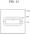
- the shape of the third opening OP3 may be a rectangle-like shape in which four corners are rounded. This is a shape that may be formed in a manufacturing process, and when the shape of the third opening OP3 is a rectangle-like shape having four rounded corners, as shown in FIG. 11 , the width (d) of the opening means a length of a longest part of the third opening OP3.
- an area of the third opening OP3 in a direction parallel to the substrate 100 may be in a range of about 49 ⁇ m 2 to about 81 ⁇ m 2 .
- the shape of the third opening OP3 may be circular.
- the width (d) of the opening described in the specification means a diameter of the third opening OP3 as shown in FIG. 12 .
- an area of the third opening OP3 in a direction parallel to the substrate 100 may be in a range of about 49 ⁇ m 2 to about 81 ⁇ m 2 .
- the shape of the third opening OP3 may be elliptical.
- the width (d) of the opening described in the specification means a diameter of a long axis of the third opening OP3 as shown in FIG. 12 .
- an area of the third opening OP3 in a direction parallel to the substrate 100 may be in a range of about 49 ⁇ m 2 to about 81 ⁇ m 2 .
- the shape of the third opening OP3 is not limited thereto, and the third opening OP3 may have one of other various shapes.
- the opening may be a polygon, a circle, an ellipse, or a shape including a plurality of sides and a curved surface connecting the sides to each other.
- the area of the third opening OP3 may be in a range of about 49 ⁇ m 2 to about 81 ⁇ m 2 .
- the width of the opening overlapping the semiconductor layers 150a and 150b may be in a range of about 7 ⁇ m to about 9 ⁇ m. In such an embodiment, the area of the opening overlapping the semiconductor layers 150a and 150b may be in a range of about 49 ⁇ m 2 to about 81 ⁇ m 2 .
- the hydrogen introduced into the semiconductor layers 150a and 150b may not be sufficiently removed, and thus the transistor may not normally operate.
- the width of the opening overlapping the semiconductor layers 150a and 150b exceeds about 9 ⁇ m or the area of the opening exceeds about 81 ⁇ m 2 , the hydrogen in the semiconductor layers 150a and 150b is excessively removed, and thus the positive shift of the threshold voltage excessively occurs, and it may not be utilized as an element.
- a range of the threshold voltage for the transistor of the display device to normally operate is between -1.0 V and 1.0 V.
- FIG. 14 to FIG. 19 illustrate results of measuring voltage (V GS )-current (I DS ) while varying a size of an opening.
- Table 1 shows mobilities and threshold voltages measured by experiments of FIG. 14 to FIG. 19 .
- Table 1 Size of opening ( ⁇ m x ⁇ m) Mobility Threshold voltage (Vth) 4 x 4 - -9.58 6 x 6 13.76 -2.00 7 x 7 11.05 -0.63 8 x 8 11.49 0.59 9 x 9 10.38 0.90 10 x 10 8.89 1.53
- the threshold voltage was in a range of -1.0 V to 1.0 V when the size of the opening was between 7 ⁇ m x 7 ⁇ m to 9 ⁇ m x 9 ⁇ m. That is, when the size of the opening is less than 7 ⁇ m x 7 ⁇ m, the threshold voltage may be a reference value or less that may normally operate as a transistor. In addition, when the size of the opening is more than 9 ⁇ m x 9 ⁇ m, the threshold voltage is excessively high, so it may be effectively utilized as an element.
- FIG. 20 to FIG. 28 illustrate cross-sectional views of a manufacturing process according to an embodiment of the invention.
- the barrier layer 110 is provided or formed on the substrate 100, and the light blocking layer 111 and the data line 171 are provided or formed on the barrier layer 110.
- the light blocking layer 111 and the data line 171 may be formed in a same process as each other, and may include a same material as each other. In such a process, a first mask may be used.
- the buffer layer 120 and a semiconductor layer 150 may be provided or formed on the light blocking layer 111 and the data line 171.
- the semiconductor layer 150 may include an oxide semiconductor.
- the semiconductor layer 150 may include an oxide semiconductor material including at least one selected from zinc (Zn), indium (In), gallium (Ga), tin (Sn), and a combination thereof.
- the semiconductor layers 150a and 150b may include IGZO.
- the semiconductor layer 150 is etched to form the first semiconductor layer 150a and the second semiconductor layer 150b.
- a second mask may be used.
- the first semiconductor layer 150a may form the first transistor T1
- the second semiconductor layer 150b may form the second transistor T2.
- a gate insulating film 140 and a gate layer 121 are provided or formed on the first semiconductor layer 150a and the second semiconductor layer 150b.
- the gate insulating film 140 and the gate layer 121 are etched to form the first gate electrode 124a, the second gate electrode 124b, and the gate insulating pattern 144.
- a third mask may be used. Since the gate insulating film 140 and the gate layer 121 are etched by a same process, the gate insulating pattern 144 may have a same shape as the first gate electrode 124a and the second gate electrode 124b.
- the intermediate film 160 and the insulating film 180 are provided or formed over the first gate electrode 124a, the second gate electrode 124b, and the gate insulating pattern 144, and the plurality of openings OP1, OP2, OP3, OP4, OP5, and OP6 are formed through the intermediate film 160 and the insulating film 180.
- a fourth mask may be used in the process of forming the openings.
- the first opening OP1 may be formed to overlap the light blocking layer 111, and the second opening OP2 may be formed to overlap the data line 171.
- the third opening OP3 is formed to overlap the drain region 155a of the first semiconductor layer 150a
- the fourth opening OP4 is formed to overlap the first gate electrode 124a
- the fifth opening OP5 is formed to overlap the drain region 155b of the second semiconductor layer 150b
- the sixth opening OP6 is formed to overlap the source region 153b of the second semiconductor layer 150b.
- the widths of the third opening OP3, the fifth opening OP5, and the sixth opening OP6 may be in a range of about 7 ⁇ m to about 9 ⁇ m.
- the areas of the third opening OP3, the fifth opening OP5, and the sixth opening OP6 may be in a range of about 49 ⁇ m 2 to about 81 ⁇ m 2 .
- the definition of the shapes and widths of the third opening OP3, the fifth opening OP5, and the sixth opening OP6 may be the same as those described above with reference to FIG. 8 to FIG. 13 .
- plasma treatment is then performed.
- the plasma treatment may be performed for 30 seconds to 90 seconds with a power in a range of 1.5 kilowatts (kW) to 2.5 kW.
- kW 1.5 kilowatts
- vacancies are formed inside the semiconductor layers 150a and 150b. This is because inert gas collides with the semiconductor layers 150a and 150b, thereby disturbing the atoms inside the semiconductor layers 150a and 150b, or releasing atoms out.
- the first electrode 191, the first connection electrode 192, and the second connection electrode 193 are provided or formed in respective openings OP1, OP2, OP3, OP4, OP5, and OP6, and on the insulating film 180.
- a fifth mask may be used.
- the first electrode 191 contacts the light blocking layer 111 through the first opening OP1 and the source region 153a of the first semiconductor layer 150a through the third opening OP3.
- the first connection electrode 192 contacts the first gate electrode 124a of the first semiconductor layer 150a through the fourth opening OP4 and the drain region 155b of the second semiconductor layer 150b through the fifth opening OP5.
- the second connection electrode 193 contacts the source region 153b of the second semiconductor layer 150b through the sixth opening OP6 and the data line 171 through the second opening OP2.
- the partition wall 350 is provided or formed on the first electrode 191, the first connection electrode 192, and the second connection electrode 193.
- the partition wall 350 includes the opening 355 overlapping the first electrode 191, and a sixth mask may be used in this process.
- a source electrode and a drain electrode are not included, and a data voltage is transmitted to each transistor through the first connection electrode 192 and the second connection electrode 193 disposed in a same layer as the first electrode 191. Therefore, in such an embodiment, the number of masks used in the manufacturing process may be reduced, such that the manufacturing process may be simplified by being performed with six masks.
- the width of the opening overlapping the semiconductor layers 150a and 150b is in a range of about 7 ⁇ m to about 9 ⁇ m, or the area thereof is in a range of about 49 ⁇ m 2 to about 81 ⁇ m 2 .
- the width or area of the opening may be determined to prevent the semiconductor layer from functioning as a conductor by excess hydrogen contained in SiNx when the display device includes a SiNx film therein for protection of an element. This is because, as described above, the larger the area of the opening, the more the number of vacancies formed by the plasma treatment increases, and the vacancies are combined with hydrogen ions inside the semiconductor layer to remove the hydrogen ions.
- an embodiment of the display device may include a SiNx film adjacent to the semiconductor layer, and may be applied to various structures if the semiconductor layer includes an oxide semiconductor. As described above, since such an embodiment of the display device may be manufactured using six masks, a source electrode is omitted, and the connection electrode disposed in a same layer as the first electrode 191 may be applied to a structure for transmitting a data voltage.
- FIG. 29 illustrates a circuit diagram of a pixel according to an embodiment of the invention.
- an embodiment of the display device includes a plurality of pixels, and each pixel may include a plurality of transistors T1, T2, and T3, a capacitor Cst, and a light emitting diode ED.
- each pixel includes a single light emitting diode ED as shown in FIG. 29 will be described in detail, but not being limited thereto.
- the plurality of transistors T1, T2, and T3 of a pixel include a first transistor T1, a second transistor T2, and a third transistor T3.
- a source electrode and a drain electrode which will be described below, are used to distinguish two electrodes disposed at opposite sides of a channel of each of the transistors T1, T2, and T3, and the source electrode and the drain electrode may be interchanged.
- a gate electrode G1 of the first transistor T1 is connected to one end of the capacitor Cst, a source electrode S1 of the first transistor T1 is connected to a driving voltage line for transmitting a driving voltage ELVDD, and a drain electrode D1 of the first transistor T1 is connected to an anode of the light emitting diode ED and the other end of the capacitor Cst.
- the first transistor T1 may receive a data voltage DAT based on a switching operation of the second transistor T2, and supply a driving current to the light emitting diode ED corresponding to a voltage stored in the capacitor Cst.
- the drain electrode D1 of the first transistor T1 may be connected to the light blocking layer 111.
- a gate electrode G2 of the second transistor T2 is connected to a first scan line that transmits a first scan signal SC, a source electrode S2 of the second transistor T2 is connected to a data line that may transmit the data voltage DAT or a reference voltage, and a drain electrode D2 of the second transistor T2 is connected to one end of the capacitor Cst and the gate electrode G1 of the first transistor T1.
- the second transistor T2 is turned on in response to the first scan signal SC to transmit the reference voltage or the data voltage DAT to the gate electrode G1 of the first transistor T1 and one end of the capacitor Cst.
- a gate electrode G3 of the third transistor T3 is connected to a second scan line for transmitting a second scan signal SS, a source electrode S3 of the third transistor T3 is connected to the other end of the capacitor Cst, the drain electrode D1 of the first transistor T1, and the anode of the light emitting diode ED, and a drain electrode D3 of the third transistor T3 is connected to an initialization voltage line for transmitting an initialization voltage INIT.
- the third transistor T3 is turned on in response to the second scan signal SS to transmit the initialization voltage INIT to the anode of the light emitting diode ED and the other end of the storage capacitor Cst, thereby initializing the anode voltage of the light emitting diode ED.
- One end of the capacitor Cst is connected to the gate electrode G1 of the first transistor T1, and the other end thereof is connected to the source electrode S3 of the third transistor T3 and the anode of the light emitting diode ED.
- the cathode of the light emitting diode ED is connected to a common voltage line for transmitting a common voltage ELVSS.
- the light emitting diode ED may emit light corresponding to a driving current outputted from the first transistor T1.
- An embodiment of the display device described above may be applied to a display device having the circuit diagram of FIG. 29 .
- this is merely an example, and the invention is not limited thereto.
Landscapes
- Engineering & Computer Science (AREA)
- Power Engineering (AREA)
- Microelectronics & Electronic Packaging (AREA)
- Physics & Mathematics (AREA)
- General Physics & Mathematics (AREA)
- Computer Hardware Design (AREA)
- Condensed Matter Physics & Semiconductors (AREA)
- Manufacturing & Machinery (AREA)
- Ceramic Engineering (AREA)
- Chemical & Material Sciences (AREA)
- Crystallography & Structural Chemistry (AREA)
- Geometry (AREA)
- Thin Film Transistor (AREA)
- Electroluminescent Light Sources (AREA)
Abstract
Description
- The disclosure relates to a display device and a manufacturing method thereof, and more particularly, to a display device and a manufacturing method thereof that does not include a source electrode and a drain electrode disposed in a same layer as a data line.
- Among display devices, a flat panel display device has been spotlighted due to desired characteristics such as light weight and thin thickness. Among flat panel display devices, a light emitting display device is a self-emissive display device that displays an image by using a light emitting diode that emits light without using a separate light source. In addition, the light emitting display device has attracted attention as a next-generation display device due to various desired characteristics such as low power consumption, high luminance, and high reaction speed.
- Such a light emitting display device typically includes a plurality of pixels including a light emitting diode, a plurality of transistors for driving the light emitting diode, and at least one capacitor.
- In a light emitting display device, an oxide semiconductor may be used as a semiconductor layer of the transistor. In such a light emitting display device, it is desired to reduce the number of masks used in a manufacturing process to simplify the process.
- Embodiments of the invention relate to a display device and a manufacturing method thereof that may stably maintain performance of a transistor including an oxide semiconductor.
- An embodiment of the invention provides a display device including: a substrate; a first semiconductor layer disposed on the substrate, where the first semiconductor layer includes a channel region and a doped region; a first gate electrode disposed to overlap the channel region of the first semiconductor layer; an intermediate film disposed on the first semiconductor layer and the first gate electrode; and a first electrode disposed on the intermediate film, where an opening is defined through the intermediate film to overlap the doped region of the first semiconductor layer, the doped region of the first semiconductor layer and the first electrode contacts each other through the opening of the intermediate film, and an area of a cross-section of the opening of the intermediate film parallel to the substrate is in a range of about 49 square micrometers (µm2) to about 81 µm2.
- In an embodiment, the first semiconductor layer may include an oxide semiconductor.
- In an embodiment, the intermediate film may include a silicon nitride.
- In an embodiment, the display device may further include an insulating film disposed between the intermediate film and the first electrode, where an entire region of the intermediate film may contact the insulating film, and the insulating film may include an organic material.
- In an embodiment, the display device may further include: a light blocking layer disposed between the substrate and the first semiconductor layer; and a buffer layer disposed between the light blocking layer and the first semiconductor layer, where an opening may be defined through the buffer layer to overlap the light blocking layer, and the first electrode and the light blocking layer may contact each other through the opening of the buffer layer.
- In an embodiment, the display device may further include: a second semiconductor layer disposed in a same layer as the first semiconductor layer, where the second semiconductor layer may include a channel region and a doped region; and a first connection electrode disposed in a same layer as the first electrode, where the first connection electrode may contact the first gate electrode and the doped region of the second semiconductor layer, and may connect the first gate electrode and the second semiconductor layer to each other.
- In an embodiment, the display device may further include: a data line disposed in a same layer as the light blocking layer; and a second connection electrode disposed in a same layer as the first electrode, where the second connection electrode may contact the data line and the doped region of the second semiconductor layer, and may connect the data line and the second semiconductor layer to each other.
- In an embodiment, a shape of a cross-section of the opening of the intermediate film parallel to the substrate may be one selected from a polygonal shape, a circular shape, an elliptical shape, and a shape including a plurality of sides and curved lines connecting the sides to each other.
- In an embodiment, a threshold voltage of the first semiconductor layer may be in a range of about -1.0 volt (V) to 1.0 V.
- Another embodiment of the invention provides a display device including: a substrate; a first semiconductor layer disposed on the substrate, where the first semiconductor layer includes a channel region and a doped region; a first gate electrode disposed to overlap the channel region of the first semiconductor layer; an intermediate film disposed on the first semiconductor layer and the first gate electrode; and a first electrode disposed on the intermediate film, where an opening is defined through the intermediate film to overlap the doped region of the first semiconductor layer, the doped region of the first semiconductor layer and the first electrode contact each other through the opening, the first semiconductor layer includes an oxide semiconductor, the intermediate film includes a silicon nitride, and a width of the opening is in a range of about 7 micrometers (µm) to about 9 µm.
- In an embodiment, a shape of a cross-section of the opening parallel to the substrate may be one selected from a polygonal shape, a circular shape, an elliptical shape, and a shape including a plurality of sides and curved lines connecting the sides to each other, where the width of the opening may be a length of a longest side when the cross-section of the opening is a polygon or the shape including the plurality of sides and the curved lines connecting the sides to each other, the width of the opening may be a length of a diameter when the cross-section of the opening is circular, and the width of the opening may be a length of a long axis when the cross-section of the opening is elliptical.
- In an embodiment, the display device may further include: a second semiconductor layer disposed in a same layer as the first semiconductor layer and including a channel region and a doped region; and a first connection electrode disposed in a same layer as the first electrode, where the first connection electrode may contact the first gate electrode and the doped region of the second semiconductor layer, and may connect the first gate electrode and the second semiconductor layer to each other.
- In an embodiment, the display device may further include: a data line disposed between the substrate and the second semiconductor layer; a buffer layer disposed between the data line and the second semiconductor layer; and a second connection electrode disposed in a same layer as the first electrode, wherein the second connection electrode may contact the data line and the doped region of the second semiconductor layer, and may connect the data line and the second semiconductor layer to each other.
- In an embodiment, a threshold voltage of the first semiconductor layer may be in a range of about -1.0 V to about 1.0 V.
- Another embodiment of the invention provides a manufacturing method of a display device, the manufacturing method including: providing a first semiconductor layer and a second semiconductor layer on a substrate; providing a gate insulating film and a gate electrode on the first semiconductor layer and the second semiconductor layer, respectively; depositing an intermediate film and an insulating film over the first semiconductor layer, the second semiconductor layer, the gate insulating film and the gate electrode, and then etching them to form an opening overlapping the first semiconductor layer and the second semiconductor layer, respectively; plasma-treating the opening; and providing a first electrode on the insulating film, wherein the first electrode may contact the first semiconductor layer through the opening, and an area of a cross-section of the opening parallel to the substrate is in a range of about 49 µm2 to about 81 µm2.
- In an embodiment, the first semiconductor layer and the second semiconductor layer may include an oxide semiconductor, and the intermediate film may include a silicon nitride.
- In an embodiment, a shape of a cross-section of the opening parallel to the substrate may be one selected from a polygonal shape, a circular shape, an elliptical shape, and a shape including a plurality of sides and curved lines connecting the sides to each other.
- In an embodiment the plasma-treating the opening may include performing the plasma-treating for 30 seconds to 90 seconds with a power in a range of 1.5 kilowatts (kW) to 2.5 kW.
- In an embodiment, the manufacturing method may further include providing a first connection electrode on the insulating film during a same process as the first electrode, where the first connection electrode may contact the gate electrode overlapping the first semiconductor layer and the second semiconductor layer, respectively, and the first connection electrode may connect the gate electrode and the second semiconductor layer to each other.
- In an embodiment, the manufacturing method may further include: providing a light blocking layer and a data line on the substrate before the providing the first semiconductor layer and the second semiconductor layer on the substrate; providing a buffer layer over the light blocking layer and the data line before the providing the first semiconductor layer and the second semiconductor layer on the substrate; and providing a second connection electrode on the insulating film during a same process as the first electrode, where the second connection electrode may contact the data line and the second semiconductor layer, respectively, and may connect the data line and the second semiconductor layer to each other.
- According to embodiments of the display device and the manufacturing method, it is possible to stably maintain performance of a transistor including an oxide semiconductor.
- At least some of the above features that accord with the invention and other features according to the invention are set out in the claims.
-
-
FIG. 1 is a cross-sectional view of a display device according to an embodiment of the invention. -
FIG. 2 and FIG. 3 illustrate enlarged cross-sectional views of a portion "A" inFIG. 1 . -
FIG. 4 andFIG. 5 illustrate graphs in which voltage-current is measured for an element of a display device having a conductor characteristic as an n+ region of an oxide semiconductor increases. -
FIG. 6 illustrates a result of measuring voltage and current in the embodiment ofFIG. 2 , andFIG. 7 illustrates a result of measuring voltage and current in the embodiment ofFIG. 3 . -
FIG. 8 to FIG. 13 illustrate cross-sectional views taken along line B-B' ofFIG. 1 . -
FIG. 14 to FIG. 19 illustrate results of measuring voltage-current while varying a size of an opening. -
FIG. 20 to FIG. 28 illustrate cross-sectional views of a manufacturing process according to an embodiment of the invention. -
FIG. 29 illustrates a circuit diagram of a pixel according to an embodiment of the invention. - The invention will now be described hereinafter with reference to the accompanying drawings, in which various embodiments of the invention are shown. This invention may, however, be embodied in many different forms, and should not be construed as limited to the embodiments set forth herein. Rather, the scope of the invention is defined by the claims.
- Parts that are irrelevant to the description will be omitted to clearly describe the disclosure, and like reference numerals designate like elements throughout the specification.
- Further, in the drawings, the size and thickness of each element are arbitrarily illustrated for ease of description, and the disclosure is not necessarily limited to those illustrated in the drawings. In the drawings, the thicknesses of layers, films, panels, regions, etc., are exaggerated for clarity. In the drawings, for ease of description, the thicknesses of some layers and areas are exaggerated.
- It will be understood that when an element such as a layer, film, region, or substrate is referred to as being "on" another element, it can be directly on the other element or intervening elements may also be present. In contrast, when an element is referred to as being "directly on" another element, there are no intervening elements present. Further, in the specification, the word "on" or "above" means disposed on or below the object portion, and does not necessarily mean disposed on the upper side of the object portion based on a gravitational direction.
- It will be understood that, although the terms "first," "second," "third" etc. may be used herein to describe various elements, components, regions, layers and/or sections, these elements, components, regions, layers and/or sections should not be limited by these terms. These terms are only used to distinguish one element, component, region, layer or section from another element, component, region, layer or section. Thus, "a first element," "component," "region," "layer" or "section" discussed below could be termed a second element, component, region, layer or section without departing from the teachings herein.
- The terminology used herein is for the purpose of describing particular embodiments only and is not intended to be limiting. As used herein, "a", "an," "the," and "at least one" do not denote a limitation of quantity, and are intended to include both the singular and plural, unless the context clearly indicates otherwise. For example, "an element" has the same meaning as "at least one element," unless the context clearly indicates otherwise. "At least one" is not to be construed as limiting "a" or "an." "Or" means "and/or." As used herein, the term "and/or" includes any and all combinations of one or more of the associated listed items. It will be further understood that the terms "comprises" and/or "comprising," or "includes" and/or "including" when used in this specification, specify the presence of stated features, regions, integers, steps, operations, elements, and/or components, but do not preclude the presence or addition of one or more other features, regions, integers, steps, operations, elements, components, and/or groups thereof.
- Furthermore, relative terms, such as "lower" or "bottom" and "upper" or "top," may be used herein to describe one element's relationship to another element as illustrated in the Figures. It will be understood that relative terms are intended to encompass different orientations of the device in addition to the orientation depicted in the Figures. For example, if the device in one of the figures is turned over, elements described as being on the "lower" side of other elements would then be oriented on "upper" sides of the other elements. The term "lower," can therefore, encompasses both an orientation of "lower" and "upper," depending on the particular orientation of the figure. Similarly, if the device in one of the figures is turned over, elements described as "below" or "beneath" other elements would then be oriented "above" the other elements. The terms "below" or "beneath" can, therefore, encompass both an orientation of above and below.
- Further, throughout the specification, the phrase "in a plan view" or "on a plane" means viewing a target portion from the top, and the phrase "in a cross-section" or "on a cross-section" means viewing a cross-section formed by vertically cutting a target portion from the side.
- "About" or "approximately" as used herein is inclusive of the stated value and means within an acceptable range of deviation for the particular value as determined by one of ordinary skill in the art, considering the measurement in question and the error associated with measurement of the particular quantity (i.e., the limitations of the measurement system). For example, "about" can mean within one or more standard deviations, or within ± 30%, 20%, 10% or 5% of the stated value.
- Unless otherwise defined, all terms (including technical and scientific terms) used herein have the same meaning as commonly understood by one of ordinary skill in the art to which this disclosure belongs. It will be further understood that terms, such as those defined in commonly used dictionaries, should be interpreted as having a meaning that is consistent with their meaning in the context of the relevant art and the present disclosure, and will not be interpreted in an idealized or overly formal sense unless expressly so defined herein.
- Embodiments are described herein with reference to cross section illustrations that are schematic illustrations of idealized embodiments. As such, variations from the shapes of the illustrations as a result, for example, of manufacturing techniques and/or tolerances, are to be expected. Thus, embodiments described herein should not be construed as limited to the particular shapes of regions as illustrated herein but are to include deviations in shapes that result, for example, from manufacturing. For example, a region illustrated or described as flat may, typically, have rough and/or nonlinear features. Moreover, sharp angles that are illustrated may be rounded. Thus, the regions illustrated in the figures are schematic in nature and their shapes are not intended to illustrate the precise shape of a region and are not intended to limit the scope of the present claims.
- Hereinafter, embodiments of the invention will be described in detail with reference to the accompanying drawings.
-
FIG. 1 is a cross-sectional view of a display device according to an embodiment of the invention. - Referring to
FIG. 1 , an embodiment of a display device has a structure in that, instead of a source electrode and a drain electrode of a transistor, afirst connection electrode 192 and asecond connection electrode 193 are disposed in a same layer as afirst electrode 191. In such an embodiment, as described above, by omitting the source electrode and the drain electrode and disposing thefirst connection electrode 192 and thesecond connection electrode 193, a mask used to form the source electrode and the drain electrode in a manufacturing process may be omitted, thereby simplifying the manufacturing process. - Hereinafter, a structure of an embodiment of the display device will be described in detail with reference to
FIG. 1 . - Referring to
FIG. 1 , in an embodiment of the display device, abarrier layer 110 is disposed on asubstrate 100 including a transparent glass or plastic. Thebarrier layer 110 may include an inorganic material, and alternatively, thebarrier layer 110 may be omitted. - In such an embodiment, a
light blocking layer 111, adata line 171, and astorage electrode line 131 are disposed on thebarrier layer 110. Since thelight blocking layer 111, thedata line 171, and thestorage electrode line 131 are disposed in a same layer as each other, thelight blocking layer 111, thedata line 171, and thestorage electrode line 131 may be formed in a same process, and may include a same material as each other. Thelight blocking layer 111 may be disposed to overlap a first transistor T1 and thesubstrate 100 in a vertical direction. Thelight blocking layer 111 may prevent external light from reachingchannel regions semiconductor layers light blocking layer 111 may be connected to thefirst electrode 191 at a first opening OP1 defined through abuffer layer 120. In such an embodiment, thedata line 171 may also be connected to thesecond connection electrode 193 at a second opening OP2 defined through thebuffer layer 120. - The
buffer layer 120 is disposed on thelight blocking layer 111, thedata line 171, and thestorage electrode line 131. Thebuffer layer 120 may insulate thesemiconductor layers light blocking layer 111, thedata line 171, and thestorage electrode line 131, and may include an organic material or an inorganic material. In one embodiment, for example, thebuffer layer 120 may include an inorganic insulating material such as a silicon nitride (SiNx), a silicon oxide (SiOx), and a silicon oxynitride (SiON), or an organic insulating material, where x may be 1 to 4. In such an embodiment, the first opening OP1 overlapping thelight blocking layer 111 and the second opening OP2 overlapping thedata line 171 are defined through thebuffer layer 120. - The semiconductor layers 150a and 150b are disposed on the
buffer layer 120. The semiconductor layers 150a and 150b may include afirst semiconductor layer 150a and asecond semiconductor layer 150b. Thefirst semiconductor layer 150a may form the first transistor T1, and the first transistor T1 may be a driving transistor. Thesecond semiconductor layer 150b may form a second transistor T2, and the second transistor T2 may be a switching transistor. - The semiconductor layers 150a and 150b may include at least one selected from amorphous silicon, polycrystalline silicon, monocrystalline silicon, and an oxide semiconductor. In an embodiment, the
semiconductor layers semiconductor layers semiconductor layers - The
first semiconductor layer 150a includes asource region 153a, adrain region 155a, and achannel region 154a disposed between thesource region 153a and thedrain region 155a. Thesource region 153a and thedrain region 155a are doped regions in which doping is performed. - In an embodiment, the
second semiconductor layer 150b includes asource region 153b, adrain region 155b, and achannel region 154b disposed between thesource region 153b and thedrain region 155b. - The
source region 153b and thedrain region 155b are doped regions in which doping is performed. - In an embodiment, a
gate insulating pattern 144 may be disposed to overlap thechannel regions semiconductor layers gate insulating pattern 144 may not substantially overlap conductive regions of thesemiconductor layers -
Gate electrodes gate insulating pattern 144. Thegate electrodes channel regions semiconductor layers substrate 100. Thefirst gate electrode 124a and thefirst semiconductor layer 150a form or collective define the first transistor T1, and thesecond gate electrode 124b and thesecond semiconductor layer 150b form or collective define the second transistor T2. - An
intermediate film 160 and an insulatingfilm 180 are disposed on thesemiconductor layers gate electrodes intermediate film 160 may be an inorganic film including an inorganic material, and the insulatingfilm 180 may include an organic material. Theintermediate film 160 may protect the transistor T1 from external moisture. Theintermediate film 160 may include at least one selected from a silicon nitride (SiNx), a silicon oxide (SiOx), and a silicon oxynitride (SiON), where x is 1 to 4. In one embodiment, for example, theintermediate film 160 may include a SiNx. In such an embodiment, penetration of moisture into an element may be effectively prevented by theintermediate film 160 since SiNx effectively blocks external moisture. However, a hydrogen content of SiNx is high, which may affect semiconductor properties of thesemiconductor layers - In an embodiment, a third opening OP3 is defined through the
intermediate film 160 and the insulatingfilm 180 to overlap thedrain region 155a of thefirst semiconductor layer 150a, a fourth opening OP4 is defined through theintermediate film 160 and the insulatingfilm 180 to overlap thefirst gate electrode 124a, a fifth opening OP5 is defined through theintermediate film 160 and the insulatingfilm 180 to overlap thedrain region 155b of thesecond semiconductor layer 150b, and a sixth opening OP6 is defined through theintermediate film 160 and the insulatingfilm 180 to overlap thesource region 153b of thesecond semiconductor layer 150b. In such an embodiment, the first opening OP1 and the second opening OP2 is defined in thebuffer layer 120 through theintermediate film 160 and the insulatingfilm 180. - In an embodiment, the third opening OP3, the fifth opening OP5, and the sixth opening OP6 are openings defined to overlap or expose the
first semiconductor layer 150a and thesecond semiconductor layer 150b. In such an embodiment, an area in a direction parallel to the substrate 100 (or a cross-sectional area) of the third opening OP4, the fifth opening OP5, and the sixth opening OP6 disposed to overlap thefirst semiconductor layer 150a and thesecond semiconductor layer 150b may be in a range of about 49 square micrometers (µm2) to about 81 µm2. In such an embodiment, a width of the third opening OP4, the fifth opening OP5, and the sixth opening OP6 may be in a range of about 7 micrometers (µm) to about 9 µm. A measurement standard of the term "width" used herein will be described in detail with reference toFIG. 8 to FIG. 13 . In an embodiment, where the opening is rectangular, a length of a longest side is a width. In an alternative embodiment, where the opening is circular, a length of a diameter is a width. In another alternative embodiment, where the opening is elliptical, a length of a largest diameter is a width. - In a case where the cross-sectional area or the width of the third opening OP4, the fifth opening OP5, and the sixth opening OP6 is too large, since the intermediate film (SiNx) contains an high amount of hydrogen, the hydrogen contained in the intermediate film may penetrate into the
semiconductor layers semiconductor layers - Referring back to
FIG. 1 , thefirst electrode 191, thefirst connection electrode 192, and thesecond connection electrode 193 are disposed on the insulatingfilm 180. Thefirst electrode 191, thefirst connection electrode 192, and thesecond connection electrode 193 may include a transparent conductive oxide, may be formed in a same process, and may include a same material as each other. In one embodiment, for example, it may include a multi-layered structure of indium tin oxide ("ITO")/Ag/ITO. - The
second connection electrode 193 is connected to thedata line 171 through the second opening OP2, and is connected to thesource region 153b of the second transistor T2 through the sixth opening OP6. In such an embodiment, thesecond connection electrode 193 connects thedata line 171 and thesource region 153b of the second transistor T2 to each other. - The
first connection electrode 192 is connected to thedrain region 155b of the second transistor T2 through the fifth opening OP5, and is connected to thefirst gate electrode 124a of the first transistor T1 through the fourth opening OP4. In such an embodiment, thefirst connection electrode 192 connects thedrain region 155b of the second transistor T2 and thefirst gate electrode 124a of the first transistor T1 to each other. - The
first electrode 191 is connected to thedrain region 155a of the first transistor T1 through the third opening OP3 to receive a voltage. Thefirst electrode 191 may also be connected to thelight blocking layer 111 through the first opening OP1, and may constantly maintain a current according to a voltage. - A
partition wall 350 is disposed on thefirst electrode 191, thefirst connection electrode 192, and thesecond connection electrode 193. In an embodiment, anopening 355 is defined through thepartition wall 350 to overlap or expose thefirst electrode 191. Alight emitting layer 360 may be disposed in theopening 355. Asecond electrode 270 is disposed on thelight emitting layer 360 and thepartition wall 350. Thefirst electrode 191, thelight emitting layer 360, and thesecond electrode 270 may form a light emitting diode LED. - In an embodiment, as shown in
FIG. 1 , the display device does not include a source electrode or a drain electrode disposed in a same layer as thedata line 171, and the source electrode or the drain electrode receives a data voltage through thefirst connection electrode 192 and thesecond connection electrode 193. In such an embodiment, separate source and drain electrodes in a same layer as thedata line 171 are not included, the number of masks may be reduced in a manufacturing process, thereby effectively reducing the cost of the manufacturing process. - In an embodiment, since the
intermediate film 160 includes SiNx, the transistor is effectively protected from external moisture. However, in a case where theintermediate film 160 includes SiNx, since SiNx contains excessive hydrogen, thesemiconductor layers semiconductor layers semiconductor layers semiconductor layers - Hereinafter, effects of embodiments of the invention will be described in detail.
-
FIG. 2 and FIG. 3 illustrate enlarged cross-sectional views of portion "A" inFIG. 1 . Referring toFIG. 2 , a width (d) of the third opening OP3 inFIG. 2 is 8 µm, and a width (d) of the third opening OP3 inFIG. 3 is 4 µm. For better comprehension and ease of description,FIG. 2 and FIG. 3 show hydrogen atoms (H) and vacancies (Vo) inside thefirst semiconductor layer 150a. - In both
FIG. 2 and FIG. 3 , since theintermediate film 160 includes SiNx, hydrogen atoms are introduced into thesemiconductor layer 150a. When a hydrogen content is increased inside thesemiconductor layer 150a, an n+ region of an oxide semiconductor increases, and an effective channel length decreases due to the increase of the n+ region of the oxide semiconductor. Therefore, thesemiconductor layer 150a may function as a conductor. -
FIG. 4 andFIG. 5 illustrate graphs in which voltage-current is measured for an element of a display device having a conductor characteristic as an n+ region of an oxide semiconductor increases.FIG. 4 andFIG. 5 illustrate results of repeated experiments, and in this case, results measured several times are shown in one graph.FIG. 4 illustrates a graph of results in which currents according to voltages are measured in a first transistor (driving transistor), andFIG. 5 illustrates a graph of results in which currents according to voltages are measured in a second transistor (switching transistor). Referring toFIG. 4 andFIG. 5 , it can be confirmed that hydrogen contained in SiNx included in the intermediate film was introduced into the oxide semiconductor layer, and accordingly, as the n+ region of the oxide semiconductor increased, the effective channel was shortened, and thus the transistor did not normally function. That is, no threshold voltage exists in the graph. -
FIG. 6 illustrates a result of measuring voltage and current in the embodiment ofFIG. 2 , andFIG. 7 illustrates a result of measuring voltage and current in the embodiment ofFIG. 3 . Referring toFIG. 6 andFIG. 7 , it can be confirmed that in the case ofFIG. 7 in which the width of the opening OP3 was 4 µm, the threshold voltage was lower than -10 volt (V), but in the case ofFIG. 6 in which the width of the opening OP3 was 8 µm, the threshold voltage was about -1.0 V that was higher than that ofFIG. 7 . - Referring to
FIG. 2, FIG. 3 ,FIG. 6 , andFIG. 7 , it is shown that the threshold voltage increases as the width of the third opening OP3 increases. Accordingly, an increase in conductor properties of the semiconductor layer due to hydrogen contained in theintermediate film 160 including SiNx may be effectively prevented by controlling the width of an opening that exposes the semiconductor layer. - In such an embodiment, the larger the area of the third opening OP3 overlapping the
semiconductor layer 150a, the higher the vacancy concentration of thesemiconductor layer 150a by the plasma treatment during the manufacturing process, and the increased vacancy is combined with a hydrogen ion to remove the hydrogen ion. - That is, when comparing
FIG. 2 and FIG. 3 , it can be seen that there are more vacancies Vo inFIG. 3 in which the third opening OP3 has a larger area. This is because the area in which the inert gas collides during plasma processing increases as the area of the third opening OP3 is wider, and the vacancies occur inside thesemiconductor layer 150a due to the collision. Since the vacancies are bonded to hydrogen ions inside thesemiconductor layer 150a, excess hydrogen is removed, and accordingly, thesemiconductor layer 150a may be effectively prevented from having conductor characteristics due to hydrogen introduced from theintermediate film 160 including SiNx. - In such an embodiment, shapes of the openings overlapping the
semiconductor layers FIG. 8 to FIG. 13 illustrate cross-sectional views taken along line B-B' ofFIG. 1 . InFIG. 8 to FIG. 13 , the third opening OP3 is shown for convenience of illustration and description, but the following description may be commonly applied to the openings overlapping thesemiconductor layers - Hereinafter, various shapes of the openings overlapping the
semiconductor layers FIG. 8 to FIG. 13 . - Referring to
FIG. 8 , in an embodiment, the shape of the third opening OP3 may be square. In such an embodiment, the width (d) of the third opening OP3 is the same as the length of one side of the square. That is, when the shape of the third opening OP3 is square, the width (d) of the opening means the length of one side of the third opening OP3 as shown inFIG. 8 . In such an embodiment, an area of the third opening OP3 in a direction parallel to thesubstrate 100 may be in a range of about 49 µm2 to about 81 µm2. - Referring to
FIG. 9 , in an alternative embodiment, the shape of the third opening OP3 may be a square-like shape in which four corners are rounded. This is a shape that may be formed in a manufacturing process, and when the shape of the third opening OP3 is a square-like shape having four rounded corners, as shown inFIG. 9 , the width (d) of the opening described herein means a length of a longest part of the third opening OP3. In such an embodiment, an area of the third opening OP3 in a direction parallel to thesubstrate 100 may be in a range of about 49 µm2 to about 81 µm2. - Referring to
FIG. 10 , in another alternative embodiment, the shape of the third opening OP3 may be rectangular. In such an embodiment, the width of the third opening OP3 is a length of a long side of the rectangle, that is, when the shape of the third opening OP3 is rectangular, as shown inFIG. 10 , the width (d) of the opening means the length of the long side. In such an embodiment, an area of the third opening OP3 in a direction parallel to thesubstrate 100 may be in a range of about 49 µm2 to about 81 µm2. - Referring to
FIG. 11 , in another alternative embodiment, the shape of the third opening OP3 may be a rectangle-like shape in which four corners are rounded. This is a shape that may be formed in a manufacturing process, and when the shape of the third opening OP3 is a rectangle-like shape having four rounded corners, as shown inFIG. 11 , the width (d) of the opening means a length of a longest part of the third opening OP3. In such an embodiment, an area of the third opening OP3 in a direction parallel to thesubstrate 100 may be in a range of about 49 µm2 to about 81 µm2. - Referring to
FIG. 12 , in another alternative embodiment, the shape of the third opening OP3 may be circular. When the shape of the third opening OP3 is circular, the width (d) of the opening described in the specification means a diameter of the third opening OP3 as shown inFIG. 12 . In such an embodiment, an area of the third opening OP3 in a direction parallel to thesubstrate 100 may be in a range of about 49 µm2 to about 81 µm2. - Referring to
FIG. 13 , in another alternative embodiment, the shape of the third opening OP3 may be elliptical. When the shape of the third opening OP3 is elliptical, the width (d) of the opening described in the specification means a diameter of a long axis of the third opening OP3 as shown inFIG. 12 . In such an embodiment, an area of the third opening OP3 in a direction parallel to thesubstrate 100 may be in a range of about 49 µm2 to about 81 µm2. - Although various shapes of the third opening OP3 have been described above, the shape of the third opening OP3 is not limited thereto, and the third opening OP3 may have one of other various shapes. In an embodiment, the opening may be a polygon, a circle, an ellipse, or a shape including a plurality of sides and a curved surface connecting the sides to each other. In such an embodiment, the area of the third opening OP3 may be in a range of about 49 µm2 to about 81 µm2.
- In an embodiment of the invention, the width of the opening overlapping the
semiconductor layers semiconductor layers - In an embodiment, when the width of the opening overlapping the
semiconductor layers semiconductor layers - In such an embodiment, when the width of the opening overlapping the
semiconductor layers semiconductor layers - A range of the threshold voltage for the transistor of the display device to normally operate is between -1.0 V and 1.0 V.
-
FIG. 14 to FIG. 19 illustrate results of measuring voltage (VGS)-current (IDS) while varying a size of an opening. - Table 1 shows mobilities and threshold voltages measured by experiments of
FIG. 14 to FIG. 19 .(Table 1) Size of opening (µm x µm) Mobility Threshold voltage (Vth) 4 x 4 - -9.58 6 x 6 13.76 -2.00 7 x 7 11.05 -0.63 8 x 8 11.49 0.59 9 x 9 10.38 0.90 10 x 10 8.89 1.53 - Referring to
FIG. 14 to FIG. 19 and Table 1, it is shown that the threshold voltage was in a range of -1.0 V to 1.0 V when the size of the opening was between 7 µm x 7 µm to 9 µm x 9 µm. That is, when the size of the opening is less than 7 µm x 7 µm, the threshold voltage may be a reference value or less that may normally operate as a transistor. In addition, when the size of the opening is more than 9 µm x 9 µm, the threshold voltage is excessively high, so it may be effectively utilized as an element. - Hereinafter, a manufacturing method of the display device according to an embodiment of the invention will be described with reference to
FIG. 20 to FIG. 28. FIG. 20 to FIG. 28 illustrate cross-sectional views of a manufacturing process according to an embodiment of the invention. - Referring first to
FIG. 20 , thebarrier layer 110 is provided or formed on thesubstrate 100, and thelight blocking layer 111 and thedata line 171 are provided or formed on thebarrier layer 110. Thelight blocking layer 111 and thedata line 171 may be formed in a same process as each other, and may include a same material as each other. In such a process, a first mask may be used. - Next, referring to
FIG. 21 , thebuffer layer 120 and asemiconductor layer 150 may be provided or formed on thelight blocking layer 111 and thedata line 171. Thesemiconductor layer 150 may include an oxide semiconductor. In one embodiment, for example, thesemiconductor layer 150 may include an oxide semiconductor material including at least one selected from zinc (Zn), indium (In), gallium (Ga), tin (Sn), and a combination thereof. In one embodiment, for example, thesemiconductor layers - Next, referring to
FIG. 22 , thesemiconductor layer 150 is etched to form thefirst semiconductor layer 150a and thesecond semiconductor layer 150b. In this process, a second mask may be used. Then, thefirst semiconductor layer 150a may form the first transistor T1, and thesecond semiconductor layer 150b may form the second transistor T2. - Next, referring to
FIG. 23 , agate insulating film 140 and agate layer 121 are provided or formed on thefirst semiconductor layer 150a and thesecond semiconductor layer 150b. - Subsequently, referring to
FIG. 24 , thegate insulating film 140 and thegate layer 121 are etched to form thefirst gate electrode 124a, thesecond gate electrode 124b, and thegate insulating pattern 144. In this process, a third mask may be used. Since thegate insulating film 140 and thegate layer 121 are etched by a same process, thegate insulating pattern 144 may have a same shape as thefirst gate electrode 124a and thesecond gate electrode 124b. - Next, referring to
FIG. 25 , theintermediate film 160 and the insulatingfilm 180 are provided or formed over thefirst gate electrode 124a, thesecond gate electrode 124b, and thegate insulating pattern 144, and the plurality of openings OP1, OP2, OP3, OP4, OP5, and OP6 are formed through theintermediate film 160 and the insulatingfilm 180. A fourth mask may be used in the process of forming the openings. The first opening OP1 may be formed to overlap thelight blocking layer 111, and the second opening OP2 may be formed to overlap thedata line 171. The third opening OP3 is formed to overlap thedrain region 155a of thefirst semiconductor layer 150a, the fourth opening OP4 is formed to overlap thefirst gate electrode 124a, the fifth opening OP5 is formed to overlap thedrain region 155b of thesecond semiconductor layer 150b, and the sixth opening OP6 is formed to overlap thesource region 153b of thesecond semiconductor layer 150b. - In such an embodiment, the widths of the third opening OP3, the fifth opening OP5, and the sixth opening OP6 may be in a range of about 7 µm to about 9 µm. In such an embodiment, the areas of the third opening OP3, the fifth opening OP5, and the sixth opening OP6 may be in a range of about 49 µm2 to about 81 µm2. In such an embodiment, the definition of the shapes and widths of the third opening OP3, the fifth opening OP5, and the sixth opening OP6 may be the same as those described above with reference to
FIG. 8 to FIG. 13 . - Referring to
FIG. 26 , plasma treatment is then performed. In an embodiment, the plasma treatment may be performed for 30 seconds to 90 seconds with a power in a range of 1.5 kilowatts (kW) to 2.5 kW. During the plasma treatment process, vacancies are formed inside thesemiconductor layers semiconductor layers semiconductor layers - Next, referring to
FIG. 27 , thefirst electrode 191, thefirst connection electrode 192, and thesecond connection electrode 193 are provided or formed in respective openings OP1, OP2, OP3, OP4, OP5, and OP6, and on the insulatingfilm 180. In this process, a fifth mask may be used. - The
first electrode 191 contacts thelight blocking layer 111 through the first opening OP1 and thesource region 153a of thefirst semiconductor layer 150a through the third opening OP3. Thefirst connection electrode 192 contacts thefirst gate electrode 124a of thefirst semiconductor layer 150a through the fourth opening OP4 and thedrain region 155b of thesecond semiconductor layer 150b through the fifth opening OP5. Thesecond connection electrode 193 contacts thesource region 153b of thesecond semiconductor layer 150b through the sixth opening OP6 and thedata line 171 through the second opening OP2. - Next, referring to
FIG. 28 , thepartition wall 350 is provided or formed on thefirst electrode 191, thefirst connection electrode 192, and thesecond connection electrode 193. Thepartition wall 350 includes theopening 355 overlapping thefirst electrode 191, and a sixth mask may be used in this process. - As described above, according to an embodiment of the manufacturing method of the display device, a source electrode and a drain electrode are not included, and a data voltage is transmitted to each transistor through the
first connection electrode 192 and thesecond connection electrode 193 disposed in a same layer as thefirst electrode 191. Therefore, in such an embodiment, the number of masks used in the manufacturing process may be reduced, such that the manufacturing process may be simplified by being performed with six masks. - In an embodiment of the display device manufactured as described above, the width of the opening overlapping the
semiconductor layers - As described above, an embodiment of the display device may include a SiNx film adjacent to the semiconductor layer, and may be applied to various structures if the semiconductor layer includes an oxide semiconductor. As described above, since such an embodiment of the display device may be manufactured using six masks, a source electrode is omitted, and the connection electrode disposed in a same layer as the
first electrode 191 may be applied to a structure for transmitting a data voltage. - Hereinafter, pixels of an embodiment of the display device will be briefly described.
FIG. 29 illustrates a circuit diagram of a pixel according to an embodiment of the invention. - Referring to
FIG. 29 , an embodiment of the display device includes a plurality of pixels, and each pixel may include a plurality of transistors T1, T2, and T3, a capacitor Cst, and a light emitting diode ED. Hereinafter, for convenience of description, an embodiment in which each pixel includes a single light emitting diode ED as shown inFIG. 29 will be described in detail, but not being limited thereto. - In an embodiment, the plurality of transistors T1, T2, and T3 of a pixel include a first transistor T1, a second transistor T2, and a third transistor T3. A source electrode and a drain electrode, which will be described below, are used to distinguish two electrodes disposed at opposite sides of a channel of each of the transistors T1, T2, and T3, and the source electrode and the drain electrode may be interchanged.
- A gate electrode G1 of the first transistor T1 is connected to one end of the capacitor Cst, a source electrode S1 of the first transistor T1 is connected to a driving voltage line for transmitting a driving voltage ELVDD, and a drain electrode D1 of the first transistor T1 is connected to an anode of the light emitting diode ED and the other end of the capacitor Cst. The first transistor T1 may receive a data voltage DAT based on a switching operation of the second transistor T2, and supply a driving current to the light emitting diode ED corresponding to a voltage stored in the capacitor Cst. The drain electrode D1 of the first transistor T1 may be connected to the
light blocking layer 111. - A gate electrode G2 of the second transistor T2 is connected to a first scan line that transmits a first scan signal SC, a source electrode S2 of the second transistor T2 is connected to a data line that may transmit the data voltage DAT or a reference voltage, and a drain electrode D2 of the second transistor T2 is connected to one end of the capacitor Cst and the gate electrode G1 of the first transistor T1. The second transistor T2 is turned on in response to the first scan signal SC to transmit the reference voltage or the data voltage DAT to the gate electrode G1 of the first transistor T1 and one end of the capacitor Cst.
- A gate electrode G3 of the third transistor T3 is connected to a second scan line for transmitting a second scan signal SS, a source electrode S3 of the third transistor T3 is connected to the other end of the capacitor Cst, the drain electrode D1 of the first transistor T1, and the anode of the light emitting diode ED, and a drain electrode D3 of the third transistor T3 is connected to an initialization voltage line for transmitting an initialization voltage INIT. The third transistor T3 is turned on in response to the second scan signal SS to transmit the initialization voltage INIT to the anode of the light emitting diode ED and the other end of the storage capacitor Cst, thereby initializing the anode voltage of the light emitting diode ED.
- One end of the capacitor Cst is connected to the gate electrode G1 of the first transistor T1, and the other end thereof is connected to the source electrode S3 of the third transistor T3 and the anode of the light emitting diode ED. The cathode of the light emitting diode ED is connected to a common voltage line for transmitting a common voltage ELVSS.
- The light emitting diode ED may emit light corresponding to a driving current outputted from the first transistor T1.
- An embodiment of the display device described above may be applied to a display device having the circuit diagram of
FIG. 29 . However, this is merely an example, and the invention is not limited thereto. - The invention should not be construed as being limited to the embodiments set forth herein. Rather, the scope of the invention is defined by the claims.
- While the invention has been particularly shown and described with reference to embodiments thereof, it will be understood by those of ordinary skill in the art that various changes in form and details may be made therein without departing from the scope of the claims.
Claims (15)
- A display device comprising:a substrate;a first semiconductor layer disposed on the substrate, wherein the first semiconductor layer includes a channel region and a doped region;a first gate electrode disposed to overlap the channel region of the first semiconductor layer;an intermediate film disposed on the first semiconductor layer and the first gate electrode; anda first electrode disposed on the intermediate film,wherein an opening is defined through the intermediate film to overlap the doped region of the first semiconductor layer, andthe doped region of the first semiconductor layer and the first electrode contact each other through the opening of the intermediate film.
- The display device of claim 1, wherein an area of a cross-section of the opening of the intermediate film parallel to the substrate is in a range of about 49 µm2 to about 81 µm2.
- The display device of claim 1 or claim 2, wherein a shape of a cross-section of the opening of the intermediate film parallel to the substrate is one selected from a polygonal shape, a circular shape, an elliptical shape, and a shape including a plurality of sides and curved lines connecting the sides to each other.
- The display device of any preceding claim, wherein a width of the opening of the intermediate film is in a range of about 7 µm to about 9 µm and wherein the width of the opening is a length of a longest side when the cross-section of the opening is a polygon or the shape including the plurality of sides and the curved lines connecting the sides to each other,
the width of the opening is a length of a diameter when the cross-section of the opening is circular, and
the width of the opening is a length of a long axis when the cross-section of the opening is elliptical. - The display device of any preceding claim, wherein the first semiconductor layer includes an oxide semiconductor, and optionally, wherein the intermediate film includes silicon nitride.
- The display device of any preceding claim, further comprising an insulating film disposed between the intermediate film and the first electrode,
wherein an entire region of the intermediate film contacts the insulating film, and
the insulating film includes an organic material. - The display device of any preceding claim, further comprising:a light blocking layer disposed between the substrate and the first semiconductor layer; anda buffer layer disposed between the light blocking layer and the first semiconductor layer,wherein an opening is defined through the buffer layer to overlap the light blocking layer, andthe first electrode and the light blocking layer contact each other through the opening of the buffer layer.
- The display device of claim 7, further comprising:a second semiconductor layer disposed in a same layer as the first semiconductor layer, wherein the second semiconductor layer includes a channel region and a doped region; anda first connection electrode disposed in a same layer as the first electrode,wherein the first connection electrode contacts the first gate electrode and the doped region of the second semiconductor layer, and connects the first gate electrode and the second semiconductor layer to each other.
- The display device of claim 8, further comprising:a data line disposed in a same layer as the light blocking layer; anda second connection electrode disposed in a same layer as the first electrode,wherein the second connection electrode contacts the data line and the doped region of the second semiconductor layer, and connects the data line and the second semiconductor layer to each other.
- The display device of any preceding claim, wherein
a threshold voltage of the first semiconductor layer is in a range of about -1.0 V to about 1.0 V. - The display device of any preceding claim, further comprising:a data line disposed between the substrate and the second semiconductor layer;a buffer layer disposed between the data line and the second semiconductor layer; anda second connection electrode disposed in a same layer as the first electrode,wherein the second connection electrode contacts the data line and the doped region of the second semiconductor layer, and connects the data line and the second semiconductor layer to each other.
- A manufacturing method of a display device according to any preceding claim, the manufacturing method comprising:providing a first semiconductor layer and a second semiconductor layer on a substrate;providing a gate insulating film and a gate electrode on the first semiconductor layer and the second semiconductor layer, respectively;depositing an intermediate film and an insulating film over the first semiconductor layer, the second semiconductor layer, the gate insulating film and the gate electrode, and then etching the intermediate film and the insulating film to form an opening overlapping the first semiconductor layer and the second semiconductor layer, respectively;plasma-treating the opening; andproviding a first electrode on the insulating film,wherein the first electrode contacts the first semiconductor layer through the opening, andan area of a cross-section of the opening parallel to the substrate is in a range of about 49 µm2 to about 81 µm2.
- The manufacturing method of claim 12, wherein
the plasma-treating the opening includes performing the plasma-treating for 30 seconds to 90 seconds with a power in a range of 1.5 kW to 2.5 kW. - The manufacturing method of claim 12 or claim 13, further comprising:providing a first connection electrode on the insulating film during a same process as the first electrode,wherein the first connection electrode contacts the gate electrode overlapping the first semiconductor layer and the second semiconductor layer, respectively, andthe first connection electrode connects the gate electrode and the second semiconductor layer to each other.
- The manufacturing method of any of claims 12 to 14, further comprising,
providing a light blocking layer and a data line on the substrate before the providing the first semiconductor layer and the second semiconductor layer on the substrate;
providing a buffer layer over the light blocking layer and the data line before the providing the first semiconductor layer and the second semiconductor layer on the substrate; and
providing a second connection electrode on the insulating film during a same process as the first electrode,
wherein the second connection electrode contacts the data line and the second semiconductor layer, respectively, and connects the data line and the second semiconductor layer to each other.
Applications Claiming Priority (1)
| Application Number | Priority Date | Filing Date | Title |
|---|---|---|---|
| KR1020200083521A KR20220006153A (en) | 2020-07-07 | 2020-07-07 | Display device and manufacturing method thereof |
Publications (1)
| Publication Number | Publication Date |
|---|---|
| EP3937241A1 true EP3937241A1 (en) | 2022-01-12 |
Family
ID=77103758
Family Applications (1)
| Application Number | Title | Priority Date | Filing Date |
|---|---|---|---|
| EP21184110.1A Pending EP3937241A1 (en) | 2020-07-07 | 2021-07-06 | Display device and manufacturing method thereof |
Country Status (4)
| Country | Link |
|---|---|
| US (1) | US11751439B2 (en) |
| EP (1) | EP3937241A1 (en) |
| KR (1) | KR20220006153A (en) |
| CN (1) | CN113972231A (en) |
Citations (4)
| Publication number | Priority date | Publication date | Assignee | Title |
|---|---|---|---|---|
| US20140284606A1 (en) * | 2013-03-25 | 2014-09-25 | Au Optronics Corp. | Method of fabricating pixel structure and pixel structure thereof |
| KR20170015179A (en) * | 2015-07-30 | 2017-02-08 | 가부시키가이샤 한도오따이 에네루기 켄큐쇼 | Semiconductor device and electronic device |
| US20170363894A1 (en) * | 2014-12-26 | 2017-12-21 | Sharp Kabushiki Kaisha | Display device |
| JP6585757B2 (en) * | 2012-01-26 | 2019-10-02 | 株式会社半導体エネルギー研究所 | Method for manufacturing semiconductor device |
Family Cites Families (10)
| Publication number | Priority date | Publication date | Assignee | Title |
|---|---|---|---|---|
| US7560789B2 (en) | 2005-05-27 | 2009-07-14 | Semiconductor Energy Laboratory Co., Ltd. | Semiconductor device |
| JP2009010242A (en) | 2007-06-29 | 2009-01-15 | Mitsubishi Electric Corp | Display device, and its manufacturing method |
| KR102241442B1 (en) | 2014-09-05 | 2021-04-16 | 엘지디스플레이 주식회사 | Thin film transistor substrate and method of fabricating the same |
| CN104393020B (en) * | 2014-11-21 | 2017-07-04 | 京东方科技集团股份有限公司 | A kind of array base palte and preparation method thereof, display device |
| KR102455093B1 (en) | 2016-01-11 | 2022-10-14 | 쑤저우 레킨 세미컨덕터 컴퍼니 리미티드 | Tft substrate, display panel and display device having the same |
| KR102568285B1 (en) * | 2017-12-28 | 2023-08-17 | 엘지디스플레이 주식회사 | Organic light emitting display panel and organic light emitting display apparatus using the same |
| KR102615707B1 (en) * | 2017-12-29 | 2023-12-18 | 엘지디스플레이 주식회사 | Organic light emitting display panel and organic light emitting display apparatus using the same |
| KR20190107227A (en) | 2018-03-07 | 2019-09-19 | 삼성디스플레이 주식회사 | Display panel and method of manufacturing of the same |
| KR102555788B1 (en) | 2018-04-30 | 2023-07-17 | 삼성디스플레이 주식회사 | Thin film transistor substrate, method of manufacturing the same, and display device including the same |
| CN110416233A (en) * | 2019-08-30 | 2019-11-05 | 合肥鑫晟光电科技有限公司 | The production method of array substrate, display panel and array substrate |
-
2020
- 2020-07-07 KR KR1020200083521A patent/KR20220006153A/en active Search and Examination
-
2021
- 2021-04-02 US US17/220,966 patent/US11751439B2/en active Active
- 2021-07-01 CN CN202110743264.6A patent/CN113972231A/en active Pending
- 2021-07-06 EP EP21184110.1A patent/EP3937241A1/en active Pending
Patent Citations (4)
| Publication number | Priority date | Publication date | Assignee | Title |
|---|---|---|---|---|
| JP6585757B2 (en) * | 2012-01-26 | 2019-10-02 | 株式会社半導体エネルギー研究所 | Method for manufacturing semiconductor device |
| US20140284606A1 (en) * | 2013-03-25 | 2014-09-25 | Au Optronics Corp. | Method of fabricating pixel structure and pixel structure thereof |
| US20170363894A1 (en) * | 2014-12-26 | 2017-12-21 | Sharp Kabushiki Kaisha | Display device |
| KR20170015179A (en) * | 2015-07-30 | 2017-02-08 | 가부시키가이샤 한도오따이 에네루기 켄큐쇼 | Semiconductor device and electronic device |
Also Published As
| Publication number | Publication date |
|---|---|
| KR20220006153A (en) | 2022-01-17 |
| US20220013608A1 (en) | 2022-01-13 |
| US11751439B2 (en) | 2023-09-05 |
| CN113972231A (en) | 2022-01-25 |
Similar Documents
| Publication | Publication Date | Title |
|---|---|---|
| KR102081283B1 (en) | Thin film semiconductor device, organic light emitting display, and method of manufacturing the same | |
| CN101958339B (en) | Organic light emitting display device and fabricationg method thereof | |
| KR20150070855A (en) | Thin film transistor array substrate, organic light-emitting display apparatus and manufacturing of the thin film transistor array substrate | |
| US8237168B2 (en) | Organic light emitting display device | |
| US20120061666A1 (en) | Semiconductor device and display device | |
| US10276722B2 (en) | Thin film transistor | |
| US11871617B2 (en) | Light emitting display device and manufacturing method thereof | |
| US20180012946A1 (en) | Thin-film transistor and organic light-emitting display device including the same | |
| US20180331167A1 (en) | Display device | |
| KR101493086B1 (en) | Organic electro-luminescence display device and manufacturing method thereof | |
| EP3937241A1 (en) | Display device and manufacturing method thereof | |
| US11437455B2 (en) | Display device and method of manufacturing the same | |
| CN113903751A (en) | Thin film transistor array substrate and display device | |
| KR102517126B1 (en) | Display device | |
| CN112086485A (en) | Display device | |
| KR102443127B1 (en) | Driving thin film transistor and organic light emitting display device comprising the same | |
| KR20080000015A (en) | Active-matrix organic electroluminescent device and method for fabricating thereof | |
| EP3955299A2 (en) | Display device and method for manufacturing thereof | |
| KR100667090B1 (en) | Fabricating method of tft and fpd using the tft | |
| EP3965165A2 (en) | Display device and manufacturing method thereof | |
| EP4177961A1 (en) | Thin-film transistor substrate, manufacturing method thereof, and display apparatus employing the thin-film transistor substrate | |
| US20240021695A1 (en) | Semiconductor device | |
| US20220199721A1 (en) | Method of manufacturing polycrystalline silicon layer, display device, and method of manufacturing display device | |
| US20220173188A1 (en) | Thin film transistor substrate, display apparatus, and method of manufacturing the thin film transistor substrate | |
| US20230060341A1 (en) | Display panel and display apparatus |
Legal Events
| Date | Code | Title | Description |
|---|---|---|---|
| PUAI | Public reference made under article 153(3) epc to a published international application that has entered the european phase |
Free format text: ORIGINAL CODE: 0009012 |
|
| STAA | Information on the status of an ep patent application or granted ep patent |
Free format text: STATUS: THE APPLICATION HAS BEEN PUBLISHED |
|
| AK | Designated contracting states |
Kind code of ref document: A1 Designated state(s): AL AT BE BG CH CY CZ DE DK EE ES FI FR GB GR HR HU IE IS IT LI LT LU LV MC MK MT NL NO PL PT RO RS SE SI SK SM TR |
|
| B565 | Issuance of search results under rule 164(2) epc |
Effective date: 20211202 |
|
| STAA | Information on the status of an ep patent application or granted ep patent |
Free format text: STATUS: REQUEST FOR EXAMINATION WAS MADE |
|
| 17P | Request for examination filed |
Effective date: 20220712 |
|
| RBV | Designated contracting states (corrected) |
Designated state(s): AL AT BE BG CH CY CZ DE DK EE ES FI FR GB GR HR HU IE IS IT LI LT LU LV MC MK MT NL NO PL PT RO RS SE SI SK SM TR |
|
| P01 | Opt-out of the competence of the unified patent court (upc) registered |
Effective date: 20230516 |