EP3936995A1 - Spezielle sperrmodus-benutzerschnittstelle - Google Patents
Spezielle sperrmodus-benutzerschnittstelle Download PDFInfo
- Publication number
- EP3936995A1 EP3936995A1 EP21193618.2A EP21193618A EP3936995A1 EP 3936995 A1 EP3936995 A1 EP 3936995A1 EP 21193618 A EP21193618 A EP 21193618A EP 3936995 A1 EP3936995 A1 EP 3936995A1
- Authority
- EP
- European Patent Office
- Prior art keywords
- input
- mode
- electronic device
- input mechanism
- touch
- Prior art date
- Legal status (The legal status is an assumption and is not a legal conclusion. Google has not performed a legal analysis and makes no representation as to the accuracy of the status listed.)
- Pending
Links
- 230000007246 mechanism Effects 0.000 claims abstract description 464
- 230000007704 transition Effects 0.000 claims abstract description 93
- 238000000034 method Methods 0.000 claims description 133
- 230000004044 response Effects 0.000 claims description 56
- XLYOFNOQVPJJNP-UHFFFAOYSA-N water Substances O XLYOFNOQVPJJNP-UHFFFAOYSA-N 0.000 claims description 47
- 238000003860 storage Methods 0.000 claims description 28
- 230000009172 bursting Effects 0.000 claims description 10
- 239000007788 liquid Substances 0.000 claims description 8
- 238000012545 processing Methods 0.000 description 54
- 230000033001 locomotion Effects 0.000 description 52
- 238000001514 detection method Methods 0.000 description 47
- 238000004891 communication Methods 0.000 description 28
- 230000003287 optical effect Effects 0.000 description 21
- 230000002093 peripheral effect Effects 0.000 description 19
- 230000000007 visual effect Effects 0.000 description 18
- 230000008569 process Effects 0.000 description 17
- 238000010586 diagram Methods 0.000 description 15
- 230000006870 function Effects 0.000 description 13
- 241000699666 Mus <mouse, genus> Species 0.000 description 11
- 238000007726 management method Methods 0.000 description 11
- 238000005516 engineering process Methods 0.000 description 10
- 230000004913 activation Effects 0.000 description 9
- 230000009182 swimming Effects 0.000 description 9
- 238000005259 measurement Methods 0.000 description 8
- 230000007613 environmental effect Effects 0.000 description 7
- 238000009499 grossing Methods 0.000 description 7
- 230000001960 triggered effect Effects 0.000 description 7
- 230000003993 interaction Effects 0.000 description 6
- 230000009471 action Effects 0.000 description 5
- 230000003213 activating effect Effects 0.000 description 5
- 238000006073 displacement reaction Methods 0.000 description 5
- 230000000977 initiatory effect Effects 0.000 description 4
- 238000012986 modification Methods 0.000 description 4
- 230000004048 modification Effects 0.000 description 4
- 230000021317 sensory perception Effects 0.000 description 4
- 238000012360 testing method Methods 0.000 description 4
- 230000001133 acceleration Effects 0.000 description 3
- 230000001413 cellular effect Effects 0.000 description 3
- 230000008859 change Effects 0.000 description 3
- 230000001149 cognitive effect Effects 0.000 description 3
- 230000000295 complement effect Effects 0.000 description 3
- 230000000694 effects Effects 0.000 description 3
- 238000004590 computer program Methods 0.000 description 2
- 230000000881 depressing effect Effects 0.000 description 2
- 238000005562 fading Methods 0.000 description 2
- 230000000717 retained effect Effects 0.000 description 2
- 239000004065 semiconductor Substances 0.000 description 2
- 230000035807 sensation Effects 0.000 description 2
- 239000007787 solid Substances 0.000 description 2
- 241000699670 Mus sp. Species 0.000 description 1
- 241001422033 Thestylus Species 0.000 description 1
- 238000004458 analytical method Methods 0.000 description 1
- 238000013459 approach Methods 0.000 description 1
- 238000003491 array Methods 0.000 description 1
- 230000006399 behavior Effects 0.000 description 1
- 230000008878 coupling Effects 0.000 description 1
- 238000010168 coupling process Methods 0.000 description 1
- 238000005859 coupling reaction Methods 0.000 description 1
- 230000009849 deactivation Effects 0.000 description 1
- 230000003111 delayed effect Effects 0.000 description 1
- 210000005069 ears Anatomy 0.000 description 1
- 229920001746 electroactive polymer Polymers 0.000 description 1
- 230000002708 enhancing effect Effects 0.000 description 1
- 230000003203 everyday effect Effects 0.000 description 1
- 230000004424 eye movement Effects 0.000 description 1
- 238000003384 imaging method Methods 0.000 description 1
- 230000010365 information processing Effects 0.000 description 1
- 239000004973 liquid crystal related substance Substances 0.000 description 1
- 230000007774 longterm Effects 0.000 description 1
- 230000014759 maintenance of location Effects 0.000 description 1
- 239000003550 marker Substances 0.000 description 1
- 238000007620 mathematical function Methods 0.000 description 1
- 229910044991 metal oxide Inorganic materials 0.000 description 1
- 150000004706 metal oxides Chemical class 0.000 description 1
- 238000010295 mobile communication Methods 0.000 description 1
- 238000003032 molecular docking Methods 0.000 description 1
- 230000002085 persistent effect Effects 0.000 description 1
- 229920000642 polymer Polymers 0.000 description 1
- 238000003672 processing method Methods 0.000 description 1
- 238000009877 rendering Methods 0.000 description 1
- 230000010076 replication Effects 0.000 description 1
- 238000005096 rolling process Methods 0.000 description 1
- 238000000926 separation method Methods 0.000 description 1
- 230000011664 signaling Effects 0.000 description 1
- 238000010897 surface acoustic wave method Methods 0.000 description 1
- 230000001755 vocal effect Effects 0.000 description 1
Images


Classifications
-
- G—PHYSICS
- G06—COMPUTING; CALCULATING OR COUNTING
- G06F—ELECTRIC DIGITAL DATA PROCESSING
- G06F1/00—Details not covered by groups G06F3/00 - G06F13/00 and G06F21/00
- G06F1/16—Constructional details or arrangements
- G06F1/1613—Constructional details or arrangements for portable computers
- G06F1/163—Wearable computers, e.g. on a belt
-
- G—PHYSICS
- G06—COMPUTING; CALCULATING OR COUNTING
- G06F—ELECTRIC DIGITAL DATA PROCESSING
- G06F1/00—Details not covered by groups G06F3/00 - G06F13/00 and G06F21/00
- G06F1/16—Constructional details or arrangements
- G06F1/1613—Constructional details or arrangements for portable computers
- G06F1/1633—Constructional details or arrangements of portable computers not specific to the type of enclosures covered by groups G06F1/1615 - G06F1/1626
- G06F1/1637—Details related to the display arrangement, including those related to the mounting of the display in the housing
- G06F1/1643—Details related to the display arrangement, including those related to the mounting of the display in the housing the display being associated to a digitizer, e.g. laptops that can be used as penpads
-
- G—PHYSICS
- G06—COMPUTING; CALCULATING OR COUNTING
- G06F—ELECTRIC DIGITAL DATA PROCESSING
- G06F1/00—Details not covered by groups G06F3/00 - G06F13/00 and G06F21/00
- G06F1/16—Constructional details or arrangements
- G06F1/1613—Constructional details or arrangements for portable computers
- G06F1/1633—Constructional details or arrangements of portable computers not specific to the type of enclosures covered by groups G06F1/1615 - G06F1/1626
- G06F1/1656—Details related to functional adaptations of the enclosure, e.g. to provide protection against EMI, shock, water, or to host detachable peripherals like a mouse or removable expansions units like PCMCIA cards, or to provide access to internal components for maintenance or to removable storage supports like CDs or DVDs, or to mechanically mount accessories
-
- G—PHYSICS
- G06—COMPUTING; CALCULATING OR COUNTING
- G06F—ELECTRIC DIGITAL DATA PROCESSING
- G06F1/00—Details not covered by groups G06F3/00 - G06F13/00 and G06F21/00
- G06F1/16—Constructional details or arrangements
- G06F1/1613—Constructional details or arrangements for portable computers
- G06F1/1633—Constructional details or arrangements of portable computers not specific to the type of enclosures covered by groups G06F1/1615 - G06F1/1626
- G06F1/1684—Constructional details or arrangements related to integrated I/O peripherals not covered by groups G06F1/1635 - G06F1/1675
- G06F1/169—Constructional details or arrangements related to integrated I/O peripherals not covered by groups G06F1/1635 - G06F1/1675 the I/O peripheral being an integrated pointing device, e.g. trackball in the palm rest area, mini-joystick integrated between keyboard keys, touch pads or touch stripes
-
- G—PHYSICS
- G06—COMPUTING; CALCULATING OR COUNTING
- G06F—ELECTRIC DIGITAL DATA PROCESSING
- G06F21/00—Security arrangements for protecting computers, components thereof, programs or data against unauthorised activity
- G06F21/30—Authentication, i.e. establishing the identity or authorisation of security principals
- G06F21/31—User authentication
- G06F21/36—User authentication by graphic or iconic representation
-
- G—PHYSICS
- G06—COMPUTING; CALCULATING OR COUNTING
- G06F—ELECTRIC DIGITAL DATA PROCESSING
- G06F3/00—Input arrangements for transferring data to be processed into a form capable of being handled by the computer; Output arrangements for transferring data from processing unit to output unit, e.g. interface arrangements
- G06F3/01—Input arrangements or combined input and output arrangements for interaction between user and computer
- G06F3/016—Input arrangements with force or tactile feedback as computer generated output to the user
-
- G—PHYSICS
- G06—COMPUTING; CALCULATING OR COUNTING
- G06F—ELECTRIC DIGITAL DATA PROCESSING
- G06F3/00—Input arrangements for transferring data to be processed into a form capable of being handled by the computer; Output arrangements for transferring data from processing unit to output unit, e.g. interface arrangements
- G06F3/01—Input arrangements or combined input and output arrangements for interaction between user and computer
- G06F3/03—Arrangements for converting the position or the displacement of a member into a coded form
- G06F3/033—Pointing devices displaced or positioned by the user, e.g. mice, trackballs, pens or joysticks; Accessories therefor
- G06F3/0354—Pointing devices displaced or positioned by the user, e.g. mice, trackballs, pens or joysticks; Accessories therefor with detection of 2D relative movements between the device, or an operating part thereof, and a plane or surface, e.g. 2D mice, trackballs, pens or pucks
- G06F3/03547—Touch pads, in which fingers can move on a surface
-
- G—PHYSICS
- G06—COMPUTING; CALCULATING OR COUNTING
- G06F—ELECTRIC DIGITAL DATA PROCESSING
- G06F3/00—Input arrangements for transferring data to be processed into a form capable of being handled by the computer; Output arrangements for transferring data from processing unit to output unit, e.g. interface arrangements
- G06F3/01—Input arrangements or combined input and output arrangements for interaction between user and computer
- G06F3/03—Arrangements for converting the position or the displacement of a member into a coded form
- G06F3/033—Pointing devices displaced or positioned by the user, e.g. mice, trackballs, pens or joysticks; Accessories therefor
- G06F3/0362—Pointing devices displaced or positioned by the user, e.g. mice, trackballs, pens or joysticks; Accessories therefor with detection of 1D translations or rotations of an operating part of the device, e.g. scroll wheels, sliders, knobs, rollers or belts
-
- G—PHYSICS
- G06—COMPUTING; CALCULATING OR COUNTING
- G06F—ELECTRIC DIGITAL DATA PROCESSING
- G06F3/00—Input arrangements for transferring data to be processed into a form capable of being handled by the computer; Output arrangements for transferring data from processing unit to output unit, e.g. interface arrangements
- G06F3/01—Input arrangements or combined input and output arrangements for interaction between user and computer
- G06F3/03—Arrangements for converting the position or the displacement of a member into a coded form
- G06F3/041—Digitisers, e.g. for touch screens or touch pads, characterised by the transducing means
- G06F3/0416—Control or interface arrangements specially adapted for digitisers
-
- G—PHYSICS
- G06—COMPUTING; CALCULATING OR COUNTING
- G06F—ELECTRIC DIGITAL DATA PROCESSING
- G06F3/00—Input arrangements for transferring data to be processed into a form capable of being handled by the computer; Output arrangements for transferring data from processing unit to output unit, e.g. interface arrangements
- G06F3/01—Input arrangements or combined input and output arrangements for interaction between user and computer
- G06F3/048—Interaction techniques based on graphical user interfaces [GUI]
- G06F3/0481—Interaction techniques based on graphical user interfaces [GUI] based on specific properties of the displayed interaction object or a metaphor-based environment, e.g. interaction with desktop elements like windows or icons, or assisted by a cursor's changing behaviour or appearance
- G06F3/04817—Interaction techniques based on graphical user interfaces [GUI] based on specific properties of the displayed interaction object or a metaphor-based environment, e.g. interaction with desktop elements like windows or icons, or assisted by a cursor's changing behaviour or appearance using icons
-
- G—PHYSICS
- G06—COMPUTING; CALCULATING OR COUNTING
- G06F—ELECTRIC DIGITAL DATA PROCESSING
- G06F3/00—Input arrangements for transferring data to be processed into a form capable of being handled by the computer; Output arrangements for transferring data from processing unit to output unit, e.g. interface arrangements
- G06F3/01—Input arrangements or combined input and output arrangements for interaction between user and computer
- G06F3/048—Interaction techniques based on graphical user interfaces [GUI]
- G06F3/0481—Interaction techniques based on graphical user interfaces [GUI] based on specific properties of the displayed interaction object or a metaphor-based environment, e.g. interaction with desktop elements like windows or icons, or assisted by a cursor's changing behaviour or appearance
- G06F3/0482—Interaction with lists of selectable items, e.g. menus
-
- G—PHYSICS
- G06—COMPUTING; CALCULATING OR COUNTING
- G06F—ELECTRIC DIGITAL DATA PROCESSING
- G06F3/00—Input arrangements for transferring data to be processed into a form capable of being handled by the computer; Output arrangements for transferring data from processing unit to output unit, e.g. interface arrangements
- G06F3/01—Input arrangements or combined input and output arrangements for interaction between user and computer
- G06F3/048—Interaction techniques based on graphical user interfaces [GUI]
- G06F3/0487—Interaction techniques based on graphical user interfaces [GUI] using specific features provided by the input device, e.g. functions controlled by the rotation of a mouse with dual sensing arrangements, or of the nature of the input device, e.g. tap gestures based on pressure sensed by a digitiser
- G06F3/0488—Interaction techniques based on graphical user interfaces [GUI] using specific features provided by the input device, e.g. functions controlled by the rotation of a mouse with dual sensing arrangements, or of the nature of the input device, e.g. tap gestures based on pressure sensed by a digitiser using a touch-screen or digitiser, e.g. input of commands through traced gestures
- G06F3/04883—Interaction techniques based on graphical user interfaces [GUI] using specific features provided by the input device, e.g. functions controlled by the rotation of a mouse with dual sensing arrangements, or of the nature of the input device, e.g. tap gestures based on pressure sensed by a digitiser using a touch-screen or digitiser, e.g. input of commands through traced gestures for inputting data by handwriting, e.g. gesture or text
-
- H—ELECTRICITY
- H04—ELECTRIC COMMUNICATION TECHNIQUE
- H04M—TELEPHONIC COMMUNICATION
- H04M1/00—Substation equipment, e.g. for use by subscribers
- H04M1/02—Constructional features of telephone sets
- H04M1/18—Telephone sets specially adapted for use in ships, mines, or other places exposed to adverse environment
-
- H—ELECTRICITY
- H04—ELECTRIC COMMUNICATION TECHNIQUE
- H04M—TELEPHONIC COMMUNICATION
- H04M1/00—Substation equipment, e.g. for use by subscribers
- H04M1/02—Constructional features of telephone sets
- H04M1/23—Construction or mounting of dials or of equivalent devices; Means for facilitating the use thereof
- H04M1/236—Construction or mounting of dials or of equivalent devices; Means for facilitating the use thereof including keys on side or rear faces
-
- H—ELECTRICITY
- H04—ELECTRIC COMMUNICATION TECHNIQUE
- H04M—TELEPHONIC COMMUNICATION
- H04M1/00—Substation equipment, e.g. for use by subscribers
- H04M1/66—Substation equipment, e.g. for use by subscribers with means for preventing unauthorised or fraudulent calling
- H04M1/667—Preventing unauthorised calls from a telephone set
- H04M1/67—Preventing unauthorised calls from a telephone set by electronic means
-
- H—ELECTRICITY
- H04—ELECTRIC COMMUNICATION TECHNIQUE
- H04M—TELEPHONIC COMMUNICATION
- H04M1/00—Substation equipment, e.g. for use by subscribers
- H04M1/72—Mobile telephones; Cordless telephones, i.e. devices for establishing wireless links to base stations without route selection
- H04M1/724—User interfaces specially adapted for cordless or mobile telephones
- H04M1/72448—User interfaces specially adapted for cordless or mobile telephones with means for adapting the functionality of the device according to specific conditions
- H04M1/72451—User interfaces specially adapted for cordless or mobile telephones with means for adapting the functionality of the device according to specific conditions according to schedules, e.g. using calendar applications
-
- G—PHYSICS
- G06—COMPUTING; CALCULATING OR COUNTING
- G06F—ELECTRIC DIGITAL DATA PROCESSING
- G06F2203/00—Indexing scheme relating to G06F3/00 - G06F3/048
- G06F2203/041—Indexing scheme relating to G06F3/041 - G06F3/045
- G06F2203/04105—Pressure sensors for measuring the pressure or force exerted on the touch surface without providing the touch position
Definitions
- the present disclosure relates generally to computer user interfaces, and more specifically to techniques for managing input mechanisms.
- electronic devices are increasingly being carried with users to assist with the users' everyday activities (e.g., tracking workout sessions). As such, the electronic devices are increasingly exposed to environmental factors (e.g., water) that can interact with the input mechanisms of the electronic devices.
- environmental factors e.g., water
- a capacitive touch detection system of the electronic device can trigger false detection of inputs and cause the electronic device to perform tasks (e.g., making phone calls) that are not intended by the user.
- Some techniques for managing input mechanisms to suppress detection and/or processing of false inputs at certain input mechanisms using electronic devices are generally cumbersome, inefficient, and/or ineffective.
- some existing techniques e.g., powering off the electronic device and starting up the electronic device again, conventional locking and unlocking mechanisms
- existing techniques are not well adapted for scenarios in which input mechanisms need to be disabled and enabled in a fast yet secure manner.
- existing techniques not only results in making important features inaccessible by the user, but also use a complex and time-consuming user interface, which may include multiple key presses or keystrokes.
- Existing techniques require more time than necessary, wasting user time and device energy. This latter consideration is particularly important in battery-operated devices.
- the present technique provides electronic devices with faster, more efficient methods and interfaces for managing input mechanisms.
- the present technique provides a special lock mode in which various input mechanisms operate to minimize detection and/or processing of inadvertent inputs and furthermore allows for one or more predefined inputs (e.g., that are unlikely to be actuated by environmental factors such as water) for signaling the user's intent to transition out of the special lock mode.
- Such methods and interfaces optionally complement or replace other methods for managing input mechanisms.
- Such methods and interfaces reduce the cognitive burden on a user and produce a more efficient human-machine interface. For battery-operated computing devices, such methods and interfaces conserve power and increase the time between battery charges.
- a method is performed at an electronic device with a first input mechanism and a second input mechanism.
- the method comprises: while the electronic device is in a first mode, wherein the first input mechanism is disabled for user input in the first mode, detecting an input via the second input mechanism; determining whether one or more characteristics of the input detected via the second input mechanism meet a set of predefined criteria; in accordance with a determination that the one or more characteristics of the input detected via the second input mechanism meet the set of predefined criteria, transitioning the electronic device into a second mode, wherein the first input mechanism is enabled for user input in the second mode; in accordance with a determination that the one or more characteristics of the input detected via the second input mechanism do not meet the set of predefined criteria, remaining in the first mode and foregoing transitioning the electronic device into the second mode.
- an electronic device comprises: a first input mechanism; a second input mechanism; one or more processors; a memory storing one or more programs configured to be executed by the one or more processors, the one or more programs including instructions for: while the electronic device is in a first mode, wherein the first input mechanism is disabled for user input in the first mode, detecting an input via the second input mechanism; determining whether one or more characteristics of the input detected via the second input mechanism meet a set of predefined criteria; in accordance with a determination that the one or more characteristics of the input detected via the second input mechanism meet the set of predefined criteria, transitioning the electronic device into a second mode, wherein the first input mechanism is enabled for user input in the second mode; in accordance with a determination that the one or more characteristics of the input detected via the second input mechanism do not meet the set of predefined criteria, remaining in the first mode and foregoing transitioning the electronic device into the second mode.
- a non-transitory computer-readable storage medium stores one or more programs configured to be executed by one or more processors of an electronic device with a first input mechanism and a second input mechanism, the one or more programs including instructions for: while the electronic device is in a first mode, wherein the first input mechanism is disabled for user input in the first mode, detecting an input via the second input mechanism; determining whether one or more characteristics of the input detected via the second input mechanism meet a set of predefined criteria; in accordance with a determination that the one or more characteristics of the input detected via the second input mechanism meet the set of predefined criteria, transitioning the electronic device into a second mode, wherein the first input mechanism is enabled for user input in the second mode; in accordance with a determination that the one or more characteristics of the input detected via the second input mechanism do not meet the set of predefined criteria, remaining in the first mode and foregoing transitioning the electronic device into the second mode.
- an electronic device comprises: a first input mechanism; a second input mechanism; means for, while the electronic device is in a first mode, wherein the first input mechanism is disabled for user input in the first mode, detecting an input via the second input mechanism; means for determining whether one or more characteristics of the input detected via the second input mechanism meet a set of predefined criteria; means for, in accordance with a determination that the one or more characteristics of the input detected via the second input mechanism meet the set of predefined criteria, transitioning the electronic device into a second mode, wherein the first input mechanism is enabled for user input in the second mode; means for, in accordance with a determination that the one or more characteristics of the input detected via the second input mechanism do not meet the set of predefined criteria, remaining in the first mode and foregoing transitioning the electronic device into the second mode.
- a transitory computer-readable storage medium stores one or more programs configured to be executed by one or more processors of an electronic device with a first input mechanism and a second input mechanism, the one or more programs including instructions for: while the electronic device is in a first mode, wherein the first input mechanism is disabled for user input in the first mode, detecting an input via the second input mechanism; determining whether one or more characteristics of the input detected via the second input mechanism meet a set of predefined criteria; in accordance with a determination that the one or more characteristics of the input detected via the second input mechanism meet the set of predefined criteria, transitioning the electronic device into a second mode, wherein the first input mechanism is enabled for user input in the second mode; in accordance with a determination that the one or more characteristics of the input detected via the second input mechanism do not meet the set of predefined criteria, remaining in the first mode and foregoing transitioning the electronic device into the second mode.
- Executable instructions for performing these functions are, optionally, included in a non-transitory computer-readable storage medium or other computer program product configured for execution by one or more processors. Executable instructions for performing these functions are, optionally, included in a transitory computer-readable storage medium or other computer program product configured for execution by one or more processors.
- devices are provided with faster, more efficient methods and interfaces for managing input mechanisms, thereby increasing the effectiveness, efficiency, and user satisfaction with such devices.
- Such methods and interfaces may complement or replace other methods for managing input mechanisms.
- FIGS. 1A-1B , 2 , 3 , 4A-4B , and 5A-5H provide a description of exemplary devices for performing the techniques for managing input mechanisms of an electronic device.
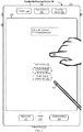
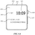
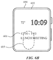
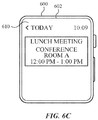
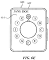
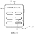
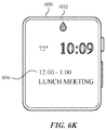
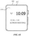
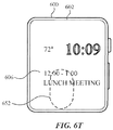
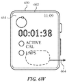
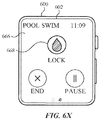
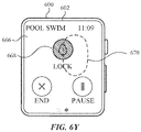
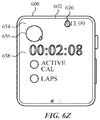
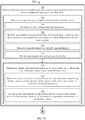
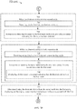
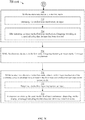
- FIGS. 6A-6Z illustrate exemplary user interfaces for managing input mechanisms.
- FIG. 7A-E include a flow diagram illustrating methods of managing event notifications in accordance with some embodiments. The user interfaces in FIGS. 6A-6Z are used to illustrate the processes described below, including the processes in FIGS. 7A-E .
- first means "first,” “second,” etc. to describe various elements, these elements should not be limited by the terms. These terms are only used to distinguish one element from another.
- a first touch could be termed a second touch, and, similarly, a second touch could be termed a first touch, without departing from the scope of the various described embodiments.
- the first touch and the second touch are both touches, but they are not the same touch.
- the device is a portable communications device, such as a mobile telephone, that also contains other functions, such as PDA and/or music player functions.
- portable multifunction devices include, without limitation, the iPhone ® , iPod Touch ® , and iPad ® devices from Apple Inc. of Cupertino, California.
- Other portable electronic devices such as laptops or tablet computers with touch-sensitive surfaces (e.g., touch screen displays and/or touchpads), are, optionally, used.
- the device is not a portable communications device, but is a desktop computer with a touch-sensitive surface (e.g., a touch screen display and/or a touchpad).
- an electronic device that includes a display and a touch-sensitive surface is described. It should be understood, however, that the electronic device optionally includes one or more other physical user-interface devices, such as a physical keyboard, a mouse, and/or a joystick.
- the device typically supports a variety of applications, such as one or more of the following: a drawing application, a presentation application, a word processing application, a website creation application, a disk authoring application, a spreadsheet application, a gaming application, a telephone application, a video conferencing application, an e-mail application, an instant messaging application, a workout support application, a photo management application, a digital camera application, a digital video camera application, a web browsing application, a digital music player application, and/or a digital video player application.
- applications such as one or more of the following: a drawing application, a presentation application, a word processing application, a website creation application, a disk authoring application, a spreadsheet application, a gaming application, a telephone application, a video conferencing application, an e-mail application, an instant messaging application, a workout support application, a photo management application, a digital camera application, a digital video camera application, a web browsing application, a digital music player application, and/or a digital video player application.
- the various applications that are executed on the device optionally use at least one common physical user-interface device, such as the touch-sensitive surface.
- One or more functions of the touch-sensitive surface as well as corresponding information displayed on the device are, optionally, adjusted and/or varied from one application to the next and/or within a respective application.
- a common physical architecture (such as the touch-sensitive surface) of the device optionally supports the variety of applications with user interfaces that are intuitive and transparent to the user.
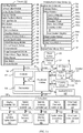
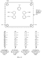
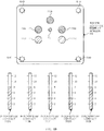
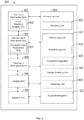
- FIG. 1A is a block diagram illustrating portable multifunction device 100 with touch-sensitive display system 112 in accordance with some embodiments.
- Touch-sensitive display 112 is sometimes called a "touch screen” for convenience and is sometimes known as or called a "touch-sensitive display system.”
- Device 100 includes memory 102 (which optionally includes one or more computer-readable storage mediums), memory controller 122, one or more processing units (CPUs) 120, peripherals interface 118, RF circuitry 108, audio circuitry 110, speaker 111, microphone 113, input/output (I/O) subsystem 106, other input control devices 116, and external port 124.
- Device 100 optionally includes one or more optical sensors 164.
- Device 100 optionally includes one or more contact intensity sensors 165 for detecting intensity of contacts on device 100 (e.g., a touch-sensitive surface such as touch-sensitive display system 112 of device 100).
- Device 100 optionally includes one or more tactile output generators 167 for generating tactile outputs on device 100 (e.g., generating tactile outputs on a touch-sensitive surface such as touch-sensitive display system 112 of device 100 or touchpad 355 of device 300). These components optionally communicate over one or more communication buses or signal lines 103.
- the term "intensity" of a contact on a touch-sensitive surface refers to the force or pressure (force per unit area) of a contact (e.g., a finger contact) on the touch-sensitive surface, or to a substitute (proxy) for the force or pressure of a contact on the touch-sensitive surface.
- the intensity of a contact has a range of values that includes at least four distinct values and more typically includes hundreds of distinct values (e.g., at least 256).
- Intensity of a contact is, optionally, determined (or measured) using various approaches and various sensors or combinations of sensors. For example, one or more force sensors underneath or adjacent to the touch-sensitive surface are, optionally, used to measure force at various points on the touch-sensitive surface.
- force measurements from multiple force sensors are combined (e.g., a weighted average) to determine an estimated force of a contact.
- a pressure-sensitive tip of a stylus is, optionally, used to determine a pressure of the stylus on the touch-sensitive surface.
- the size of the contact area detected on the touch-sensitive surface and/or changes thereto, the capacitance of the touch-sensitive surface proximate to the contact and/or changes thereto, and/or the resistance of the touch-sensitive surface proximate to the contact and/or changes thereto are, optionally, used as a substitute for the force or pressure of the contact on the touch-sensitive surface.
- the substitute measurements for contact force or pressure are used directly to determine whether an intensity threshold has been exceeded (e.g., the intensity threshold is described in units corresponding to the substitute measurements).
- the substitute measurements for contact force or pressure are converted to an estimated force or pressure, and the estimated force or pressure is used to determine whether an intensity threshold has been exceeded (e.g., the intensity threshold is a pressure threshold measured in units of pressure).
- intensity of a contact as an attribute of a user input allows for user access to additional device functionality that may otherwise not be accessible by the user on a reduced-size device with limited real estate for displaying affordances (e.g., on a touch-sensitive display) and/or receiving user input (e.g., via a touch-sensitive display, a touch-sensitive surface, or a physical/mechanical control such as a knob or a button).
- the term "tactile output” refers to physical displacement of a device relative to a previous position of the device, physical displacement of a component (e.g., a touch-sensitive surface) of a device relative to another component (e.g., housing) of the device, or displacement of the component relative to a center of mass of the device that will be detected by a user with the user's sense of touch.
- a component e.g., a touch-sensitive surface
- another component e.g., housing
- the tactile output generated by the physical displacement will be interpreted by the user as a tactile sensation corresponding to a perceived change in physical characteristics of the device or the component of the device.
- a touch-sensitive surface e.g., a touch-sensitive display or trackpad
- movement of a touch-sensitive surface is, optionally, interpreted by the user as a "down click" or "up click" of a physical actuator button.
- a user will feel a tactile sensation such as an "down click” or “up click” even when there is no movement of a physical actuator button associated with the touch-sensitive surface that is physically pressed (e.g., displaced) by the user's movements.
- movement of the touch-sensitive surface is, optionally, interpreted or sensed by the user as "roughness" of the touch-sensitive surface, even when there is no change in smoothness of the touch-sensitive surface. While such interpretations of touch by a user will be subject to the individualized sensory perceptions of the user, there are many sensory perceptions of touch that are common to a large majority of users.
- a tactile output is described as corresponding to a particular sensory perception of a user (e.g., an "up click,” a “down click,” “roughness")
- the generated tactile output corresponds to physical displacement of the device or a component thereof that will generate the described sensory perception for a typical (or average) user.
- device 100 is only one example of a portable multifunction device, and that device 100 optionally has more or fewer components than shown, optionally combines two or more components, or optionally has a different configuration or arrangement of the components.
- the various components shown in FIG. 1A are implemented in hardware, software, or a combination of both hardware and software, including one or more signal processing and/or application-specific integrated circuits.
- Memory 102 optionally includes high-speed random access memory and optionally also includes non-volatile memory, such as one or more magnetic disk storage devices, flash memory devices, or other non-volatile solid-state memory devices.
- Memory controller 122 optionally controls access to memory 102 by other components of device 100.
- Peripherals interface 118 can be used to couple input and output peripherals of the device to CPU 120 and memory 102.
- the one or more processors 120 run or execute various software programs and/or sets of instructions stored in memory 102 to perform various functions for device 100 and to process data.
- peripherals interface 118, CPU 120, and memory controller 122 are, optionally, implemented on a single chip, such as chip 104. In some other embodiments, they are, optionally, implemented on separate chips.
- RF (radio frequency) circuitry 108 receives and sends RF signals, also called electromagnetic signals.
- RF circuitry 108 converts electrical signals to/from electromagnetic signals and communicates with communications networks and other communications devices via the electromagnetic signals.
- RF circuitry 108 optionally includes well-known circuitry for performing these functions, including but not limited to an antenna system, an RF transceiver, one or more amplifiers, a tuner, one or more oscillators, a digital signal processor, a CODEC chipset, a subscriber identity module (SIM) card, memory, and so forth.
- an antenna system an RF transceiver, one or more amplifiers, a tuner, one or more oscillators, a digital signal processor, a CODEC chipset, a subscriber identity module (SIM) card, memory, and so forth.
- SIM subscriber identity module
- RF circuitry 108 optionally communicates with networks, such as the Internet, also referred to as the World Wide Web (WWW), an intranet and/or a wireless network, such as a cellular telephone network, a wireless local area network (LAN) and/or a metropolitan area network (MAN), and other devices by wireless communication.
- the RF circuitry 108 optionally includes well-known circuitry for detecting near field communication (NFC) fields, such as by a short-range communication radio.
- NFC near field communication
- the wireless communication optionally uses any of a plurality of communications standards, protocols, and technologies, including but not limited to Global System for Mobile Communications (GSM), Enhanced Data GSM Environment (EDGE), high-speed downlink packet access (HSDPA), high-speed uplink packet access (HSUPA), Evolution, Data-Only (EV-DO), HSPA, HSPA+, Dual-Cell HSPA (DC-HSPDA), long term evolution (LTE), near field communication (NFC), wideband code division multiple access (W-CDMA), code division multiple access (CDMA), time division multiple access (TDMA), Bluetooth, Bluetooth Low Energy (BTLE), Wireless Fidelity (Wi-Fi) (e.g., IEEE 802.11a, IEEE 802.11b, IEEE 802.11g, IEEE 802.11n, and/or IEEE 802.11ac), voice over Internet Protocol (VoIP), Wi-MAX, a protocol for e-mail (e.g., Internet message access protocol (IMAP) and/or post office protocol (POP)), instant messaging (e.
- Audio circuitry 110, speaker 111, and microphone 113 provide an audio interface between a user and device 100.
- Audio circuitry 110 receives audio data from peripherals interface 118, converts the audio data to an electrical signal, and transmits the electrical signal to speaker 111.
- Speaker 111 converts the electrical signal to human-audible sound waves.
- Audio circuitry 110 also receives electrical signals converted by microphone 113 from sound waves.
- Audio circuitry 110 converts the electrical signal to audio data and transmits the audio data to peripherals interface 118 for processing. Audio data is, optionally, retrieved from and/or transmitted to memory 102 and/or RF circuitry 108 by peripherals interface 118.
- audio circuitry 110 also includes a headset jack (e.g., 212, FIG. 2 ). The headset jack provides an interface between audio circuitry 110 and removable audio input/output peripherals, such as output-only headphones or a headset with both output (e.g., a headphone for one or both ears) and input (e.g., a microphone
- I/O subsystem 106 couples input/output peripherals on device 100, such as touch screen 112 and other input control devices 116, to peripherals interface 118.
- I/O subsystem 106 optionally includes display controller 156, optical sensor controller 158, intensity sensor controller 159, haptic feedback controller 161, and one or more input controllers 160 for other input or control devices.
- the one or more input controllers 160 receive/send electrical signals from/to other input control devices 116.
- the other input control devices 116 optionally include physical buttons (e.g., push buttons, rocker buttons, etc.), dials, slider switches, joysticks, click wheels, and so forth.
- input controller(s) 160 are, optionally, coupled to any (or none) of the following: a keyboard, an infrared port, a USB port, and a pointer device such as a mouse.
- the one or more buttons optionally include an up/down button for volume control of speaker 111 and/or microphone 113.
- the one or more buttons optionally include a push button (e.g., 206, FIG. 2 ).
- a quick press of the push button optionally disengages a lock of touch screen 112 or optionally begins a process that uses gestures on the touch screen to unlock the device, as described in U.S. Patent Application 11/322,549, "Unlocking a Device by Performing Gestures on an Unlock Image," filed December 23, 2005 , U.S. Pat. No. 7,657,849 , which is hereby incorporated by reference in its entirety.
- a longer press of the push button e.g., 206) optionally turns power to device 100 on or off.
- the functionality of one or more of the buttons are, optionally, user-customizable.
- Touch screen 112 is used to implement virtual or soft buttons and one or more soft keyboards.
- Touch-sensitive display 112 provides an input interface and an output interface between the device and a user.
- Display controller 156 receives and/or sends electrical signals from/to touch screen 112.
- Touch screen 112 displays visual output to the user.
- the visual output optionally includes graphics, text, icons, video, and any combination thereof (collectively termed "graphics"). In some embodiments, some or all of the visual output optionally corresponds to user-interface objects.
- Touch screen 112 has a touch-sensitive surface, sensor, or set of sensors that accepts input from the user based on haptic and/or tactile contact.
- Touch screen 112 and display controller 156 (along with any associated modules and/or sets of instructions in memory 102) detect contact (and any movement or breaking of the contact) on touch screen 112 and convert the detected contact into interaction with user-interface objects (e.g., one or more soft keys, icons, web pages, or images) that are displayed on touch screen 112.
- user-interface objects e.g., one or more soft keys, icons, web pages, or images
- a point of contact between touch screen 112 and the user corresponds to a finger of the user.
- Touch screen 112 optionally uses LCD (liquid crystal display) technology, LPD (light emitting polymer display) technology, or LED (light emitting diode) technology, although other display technologies are used in other embodiments.
- Touch screen 112 and display controller 156 optionally detect contact and any movement or breaking thereof using any of a plurality of touch sensing technologies now known or later developed, including but not limited to capacitive, resistive, infrared, and surface acoustic wave technologies, as well as other proximity sensor arrays or other elements for determining one or more points of contact with touch screen 112.
- touch sensing technologies now known or later developed, including but not limited to capacitive, resistive, infrared, and surface acoustic wave technologies, as well as other proximity sensor arrays or other elements for determining one or more points of contact with touch screen 112.
- projected mutual capacitance sensing technology is used, such as that found in the iPhone ® and iPod Touch ® from Apple Inc. of Cupertino, California.
- a touch-sensitive display in some embodiments of touch screen 112 is, optionally, analogous to the multi-touch sensitive touchpads described in the following U.S. Patents: 6,323,846 (Westerman et al. ), 6,570,557 (Westerman et al. ), and/or 6,677,932 (Westerman ), and/or U.S. Patent Publication 2002/0015024A1 , each of which is hereby incorporated by reference in its entirety.
- touch screen 112 displays visual output from device 100, whereas touch-sensitive touchpads do not provide visual output.
- a touch-sensitive display in some embodiments of touch screen 112 is described in the following applications: (1) U.S. Patent Application No. 11/381,313, "Multipoint Touch Surface Controller,” filed May 2, 2006 ; (2) U.S. Patent Application No. 10/840,862, “Multipoint Touchscreen,” filed May 6, 2004 ; (3) U.S. Patent Application No. 10/903,964, "Gestures For Touch Sensitive Input Devices," filed July 30, 2004 ; (4) U.S. Patent Application No. 11/048,264, “Gestures For Touch Sensitive Input Devices,” filed January 31, 2005 ; (5) U.S. Patent Application No.
- Touch screen 112 optionally has a video resolution in excess of 100 dpi. In some embodiments, the touch screen has a video resolution of approximately 160 dpi.
- the user optionally makes contact with touch screen 112 using any suitable object or appendage, such as a stylus, a finger, and so forth.
- the user interface is designed to work primarily with finger-based contacts and gestures, which can be less precise than stylus-based input due to the larger area of contact of a finger on the touch screen.
- the device translates the rough finger-based input into a precise pointer/cursor position or command for performing the actions desired by the user.
- device 100 in addition to the touch screen, device 100 optionally includes a touchpad (not shown) for activating or deactivating particular functions.
- the touchpad is a touch-sensitive area of the device that, unlike the touch screen, does not display visual output.
- the touchpad is, optionally, a touch-sensitive surface that is separate from touch screen 112 or an extension of the touch-sensitive surface formed by the touch screen.
- Power system 162 for powering the various components.
- Power system 162 optionally includes a power management system, one or more power sources (e.g., battery, alternating current (AC)), a recharging system, a power failure detection circuit, a power converter or inverter, a power status indicator (e.g., a light-emitting diode (LED)) and any other components associated with the generation, management and distribution of power in portable devices.
- power sources e.g., battery, alternating current (AC)
- AC alternating current
- a recharging system e.g., a recharging system
- a power failure detection circuit e.g., a power failure detection circuit
- a power converter or inverter e.g., a power converter or inverter
- a power status indicator e.g., a light-emitting diode (LED)
- Device 100 optionally also includes one or more optical sensors 164.
- FIG. 1A shows an optical sensor coupled to optical sensor controller 158 in I/O subsystem 106.
- Optical sensor 164 optionally includes charge-coupled device (CCD) or complementary metal-oxide semiconductor (CMOS) phototransistors.
- CCD charge-coupled device
- CMOS complementary metal-oxide semiconductor
- Optical sensor 164 receives light from the environment, projected through one or more lenses, and converts the light to data representing an image.
- imaging module 143 also called a camera module
- optical sensor 164 optionally captures still images or video.
- an optical sensor is located on the back of device 100, opposite touch screen display 112 on the front of the device so that the touch screen display is enabled for use as a viewfinder for still and/or video image acquisition.
- an optical sensor is located on the front of the device so that the user's image is, optionally, obtained for video conferencing while the user views the other video conference participants on the touch screen display.
- the position of optical sensor 164 can be changed by the user (e.g., by rotating the lens and the sensor in the device housing) so that a single optical sensor 164 is used along with the touch screen display for both video conferencing and still and/or video image acquisition.
- Device 100 optionally also includes one or more contact intensity sensors 165.
- FIG. 1A shows a contact intensity sensor coupled to intensity sensor controller 159 in I/O subsystem 106.
- Contact intensity sensor 165 optionally includes one or more piezoresistive strain gauges, capacitive force sensors, electric force sensors, piezoelectric force sensors, optical force sensors, capacitive touch-sensitive surfaces, or other intensity sensors (e.g., sensors used to measure the force (or pressure) of a contact on a touch-sensitive surface).
- Contact intensity sensor 165 receives contact intensity information (e.g., pressure information or a proxy for pressure information) from the environment.
- contact intensity information e.g., pressure information or a proxy for pressure information
- At least one contact intensity sensor is collocated with, or proximate to, a touch-sensitive surface (e.g., touch-sensitive display system 112). In some embodiments, at least one contact intensity sensor is located on the back of device 100, opposite touch screen display 112, which is located on the front of device 100.
- a touch-sensitive surface e.g., touch-sensitive display system 112
- at least one contact intensity sensor is located on the back of device 100, opposite touch screen display 112, which is located on the front of device 100.
- Device 100 optionally also includes one or more proximity sensors 166.
- FIG. 1A shows proximity sensor 166 coupled to peripherals interface 118. Alternately, proximity sensor 166 is, optionally, coupled to input controller 160 in I/O subsystem 106. Proximity sensor 166 optionally performs as described in U.S. Patent Application Nos.
- the proximity sensor turns off and disables touch screen 112 when the multifunction device is placed near the user's ear (e.g., when the user is making a phone call).
- Device 100 optionally also includes one or more tactile output generators 167.
- FIG. 1A shows a tactile output generator coupled to haptic feedback controller 161 in I/O subsystem 106.
- Tactile output generator 167 optionally includes one or more electroacoustic devices such as speakers or other audio components and/or electromechanical devices that convert energy into linear motion such as a motor, solenoid, electroactive polymer, piezoelectric actuator, electrostatic actuator, or other tactile output generating component (e.g., a component that converts electrical signals into tactile outputs on the device).
- Contact intensity sensor 165 receives tactile feedback generation instructions from haptic feedback module 133 and generates tactile outputs on device 100 that are capable of being sensed by a user of device 100.
- At least one tactile output generator is collocated with, or proximate to, a touch-sensitive surface (e.g., touch-sensitive display system 112) and, optionally, generates a tactile output by moving the touch-sensitive surface vertically (e.g., in/out of a surface of device 100) or laterally (e.g., back and forth in the same plane as a surface of device 100).
- a touch-sensitive surface e.g., touch-sensitive display system 112
- at least one tactile output generator sensor is located on the back of device 100, opposite touch screen display 112, which is located on the front of device 100.
- Device 100 optionally also includes one or more accelerometers 168.
- FIG. 1A shows accelerometer 168 coupled to peripherals interface 118.
- accelerometer 168 is, optionally, coupled to an input controller 160 in I/O subsystem 106.
- Accelerometer 168 optionally performs as described in U.S. Patent Publication No. 20050190059 , "Acceleration-based Theft Detection System for Portable Electronic Devices," and U.S. Patent Publication No. 20060017692 , “Methods And Apparatuses For Operating A Portable Device Based On An Accelerometer,” both of which are incorporated by reference herein in their entirety.
- information is displayed on the touch screen display in a portrait view or a landscape view based on an analysis of data received from the one or more accelerometers.
- Device 100 optionally includes, in addition to accelerometer(s) 168, a magnetometer (not shown) and a GPS (or GLONASS or other global navigation system) receiver (not shown) for obtaining information concerning the location and orientation (e.g., portrait or landscape) of device 100.
- the software components stored in memory 102 include operating system 126, communication module (or set of instructions) 128, contact/motion module (or set of instructions) 130, graphics module (or set of instructions) 132, text input module (or set of instructions) 134, Global Positioning System (GPS) module (or set of instructions) 135, and applications (or sets of instructions) 136.
- memory 102 FIG. 1A or 370 ( FIG. 3 ) stores device/global internal state 157, as shown in FIGS. 1A and 3 .
- Device/global internal state 157 includes one or more of: active application state, indicating which applications, if any, are currently active; display state, indicating what applications, views or other information occupy various regions of touch screen display 112; sensor state, including information obtained from the device's various sensors and input control devices 116; and location information concerning the device's location and/or attitude.
- Operating system 126 e.g., Darwin, RTXC, LINUX, UNIX, OS X, iOS, WINDOWS, or an embedded operating system such as VxWorks
- Operating system 126 includes various software components and/or drivers for controlling and managing general system tasks (e.g., memory management, storage device control, power management, etc.) and facilitates communication between various hardware and software components.
- Communication module 128 facilitates communication with other devices over one or more external ports 124 and also includes various software components for handling data received by RF circuitry 108 and/or external port 124.
- External port 124 e.g., Universal Serial Bus (USB), FIREWIRE, etc.
- USB Universal Serial Bus
- FIREWIRE FireWire
- the external port is a multi-pin (e.g., 30-pin) connector that is the same as, or similar to and/or compatible with, the 30-pin connector used on iPod ® (trademark of Apple Inc.) devices.
- Contact/motion module 130 optionally detects contact with touch screen 112 (in conjunction with display controller 156) and other touch-sensitive devices (e.g., a touchpad or physical click wheel).
- Contact/motion module 130 includes various software components for performing various operations related to detection of contact, such as determining if contact has occurred (e.g., detecting a finger-down event), determining an intensity of the contact (e.g., the force or pressure of the contact or a substitute for the force or pressure of the contact), determining if there is movement of the contact and tracking the movement across the touch-sensitive surface (e.g., detecting one or more finger-dragging events), and determining if the contact has ceased (e.g., detecting a finger-up event or a break in contact).
- Contact/motion module 130 receives contact data from the touch-sensitive surface. Determining movement of the point of contact, which is represented by a series of contact data, optionally includes determining speed (magnitude), velocity (magnitude and direction), and/or an acceleration (a change in magnitude and/or direction) of the point of contact. These operations are, optionally, applied to single contacts (e.g., one finger contacts) or to multiple simultaneous contacts (e.g., "multitouch"/multiple finger contacts). In some embodiments, contact/motion module 130 and display controller 156 detect contact on a touchpad.
- contact/motion module 130 uses a set of one or more intensity thresholds to determine whether an operation has been performed by a user (e.g., to determine whether a user has "clicked" on an icon).
- at least a subset of the intensity thresholds are determined in accordance with software parameters (e.g., the intensity thresholds are not determined by the activation thresholds of particular physical actuators and can be adjusted without changing the physical hardware of device 100). For example, a mouse "click" threshold of a trackpad or touch screen display can be set to any of a large range of predefined threshold values without changing the trackpad or touch screen display hardware.
- a user of the device is provided with software settings for adjusting one or more of the set of intensity thresholds (e.g., by adjusting individual intensity thresholds and/or by adjusting a plurality of intensity thresholds at once with a system-level click "intensity" parameter).
- Contact/motion module 130 optionally detects a gesture input by a user.
- Different gestures on the touch-sensitive surface have different contact patterns (e.g., different motions, timings, and/or intensities of detected contacts).
- a gesture is, optionally, detected by detecting a particular contact pattern.
- detecting a finger tap gesture includes detecting a finger-down event followed by detecting a finger-up (liftoff) event at the same position (or substantially the same position) as the finger-down event (e.g., at the position of an icon).
- detecting a finger swipe gesture on the touch-sensitive surface includes detecting a finger-down event followed by detecting one or more finger-dragging events, and subsequently followed by detecting a finger-up (liftoff) event.
- Graphics module 132 includes various known software components for rendering and displaying graphics on touch screen 112 or other display, including components for changing the visual impact (e.g., brightness, transparency, saturation, contrast, or other visual property) of graphics that are displayed.
- graphics includes any object that can be displayed to a user, including, without limitation, text, web pages, icons (such as user-interface objects including soft keys), digital images, videos, animations, and the like.
- graphics module 132 stores data representing graphics to be used. Each graphic is, optionally, assigned a corresponding code. Graphics module 132 receives, from applications etc., one or more codes specifying graphics to be displayed along with, if necessary, coordinate data and other graphic property data, and then generates screen image data to output to display controller 156.
- Haptic feedback module 133 includes various software components for generating instructions used by tactile output generator(s) 167 to produce tactile outputs at one or more locations on device 100 in response to user interactions with device 100.
- Text input module 134 which is, optionally, a component of graphics module 132, provides soft keyboards for entering text in various applications (e.g., contacts 137, e-mail 140, IM 141, browser 147, and any other application that needs text input).
- applications e.g., contacts 137, e-mail 140, IM 141, browser 147, and any other application that needs text input).
- GPS module 135 determines the location of the device and provides this information for use in various applications (e.g., to telephone 138 for use in location-based dialing; to camera 143 as picture/video metadata; and to applications that provide location-based services such as weather widgets, local yellow page widgets, and map/navigation widgets).
- applications e.g., to telephone 138 for use in location-based dialing; to camera 143 as picture/video metadata; and to applications that provide location-based services such as weather widgets, local yellow page widgets, and map/navigation widgets).
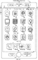
- Applications 136 optionally include the following modules (or sets of instructions), or a subset or superset thereof:
- Examples of other applications 136 that are, optionally, stored in memory 102 include other word processing applications, other image editing applications, drawing applications, presentation applications, JAVA-enabled applications, encryption, digital rights management, voice recognition, and voice replication.
- contacts module 137 are, optionally, used to manage an address book or contact list (e.g., stored in application internal state 192 of contacts module 137 in memory 102 or memory 370), including: adding name(s) to the address book; deleting name(s) from the address book; associating telephone number(s), e-mail address(es), physical address(es) or other information with a name; associating an image with a name; categorizing and sorting names; providing telephone numbers or e-mail addresses to initiate and/or facilitate communications by telephone 138, video conference module 139, e-mail 140, or IM 141; and so forth.
- an address book or contact list e.g., stored in application internal state 192 of contacts module 137 in memory 102 or memory 370
- telephone module 138 are optionally, used to enter a sequence of characters corresponding to a telephone number, access one or more telephone numbers in contacts module 137, modify a telephone number that has been entered, dial a respective telephone number, conduct a conversation, and disconnect or hang up when the conversation is completed.
- the wireless communication optionally uses any of a plurality of communications standards, protocols, and technologies.
- video conference module 139 includes executable instructions to initiate, conduct, and terminate a video conference between a user and one or more other participants in accordance with user instructions.
- e-mail client module 140 includes executable instructions to create, send, receive, and manage e-mail in response to user instructions.
- e-mail client module 140 makes it very easy to create and send e-mails with still or video images taken with camera module 143.
- the instant messaging module 141 includes executable instructions to enter a sequence of characters corresponding to an instant message, to modify previously entered characters, to transmit a respective instant message (for example, using a Short Message Service (SMS) or Multimedia Message Service (MMS) protocol for telephony-based instant messages or using XMPP, SIMPLE, or IMPS for Internet-based instant messages), to receive instant messages, and to view received instant messages.
- SMS Short Message Service
- MMS Multimedia Message Service
- XMPP extensible Markup Language
- SIMPLE Session Initiation Protocol
- IMPS Internet Messaging Protocol
- transmitted and/or received instant messages optionally include graphics, photos, audio files, video files and/or other attachments as are supported in an MMS and/or an Enhanced Messaging Service (EMS).
- EMS Enhanced Messaging Service
- instant messaging refers to both telephony-based messages (e.g., messages sent using SMS or MMS) and Internet-based messages (e.g., messages sent using XMP
- workout support module 142 includes executable instructions to create workouts (e.g., with time, distance, and/or calorie burning goals); communicate with workout sensors (sports devices); receive workout sensor data; calibrate sensors used to monitor a workout; select and play music for a workout; and display, store, and transmit workout data.
- create workouts e.g., with time, distance, and/or calorie burning goals
- communicate with workout sensors sports devices
- receive workout sensor data calibrate sensors used to monitor a workout
- select and play music for a workout and display, store, and transmit workout data.
- camera module 143 includes executable instructions to capture still images or video (including a video stream) and store them into memory 102, modify characteristics of a still image or video, or delete a still image or video from memory 102.
- image management module 144 includes executable instructions to arrange, modify (e.g., edit), or otherwise manipulate, label, delete, present (e.g., in a digital slide show or album), and store still and/or video images.
- modify e.g., edit
- present e.g., in a digital slide show or album
- browser module 147 includes executable instructions to browse the Internet in accordance with user instructions, including searching, linking to, receiving, and displaying web pages or portions thereof, as well as attachments and other files linked to web pages.
- calendar module 148 includes executable instructions to create, display, modify, and store calendars and data associated with calendars (e.g., calendar entries, to-do lists, etc.) in accordance with user instructions.
- widget modules 149 are mini-applications that are, optionally, downloaded and used by a user (e.g., weather widget 149-1, stocks widget 149-2, calculator widget 149-3, alarm clock widget 149-4, and dictionary widget 149-5) or created by the user (e.g., user-created widget 149-6).
- a widget includes an HTML (Hypertext Markup Language) file, a CSS (Cascading Style Sheets) file, and a JavaScript file.
- a widget includes an XML (Extensible Markup Language) file and a JavaScript file (e.g., Yahoo! Widgets).
- the widget creator module 150 are, optionally, used by a user to create widgets (e.g., turning a user-specified portion of a web page into a widget).
- search module 151 includes executable instructions to search for text, music, sound, image, video, and/or other files in memory 102 that match one or more search criteria (e.g., one or more user-specified search terms) in accordance with user instructions.
- search criteria e.g., one or more user-specified search terms
- video and music player module 152 includes executable instructions that allow the user to download and play back recorded music and other sound files stored in one or more file formats, such as MP3 or AAC files, and executable instructions to display, present, or otherwise play back videos (e.g., on touch screen 112 or on an external, connected display via external port 124).
- device 100 optionally includes the functionality of an MP3 player, such as an iPod (trademark of Apple Inc.).
- notes module 153 includes executable instructions to create and manage notes, to-do lists, and the like in accordance with user instructions.
- map module 154 are, optionally, used to receive, display, modify, and store maps and data associated with maps (e.g., driving directions, data on stores and other points of interest at or near a particular location, and other location-based data) in accordance with user instructions.
- maps e.g., driving directions, data on stores and other points of interest at or near a particular location, and other location-based data
- online video module 155 includes instructions that allow the user to access, browse, receive (e.g., by streaming and/or download), play back (e.g., on the touch screen or on an external, connected display via external port 124), send an e-mail with a link to a particular online video, and otherwise manage online videos in one or more file formats, such as H.264.
- instant messaging module 141 rather than e-mail client module 140, is used to send a link to a particular online video.
- modules and applications corresponds to a set of executable instructions for performing one or more functions described above and the methods described in this application (e.g., the computer-implemented methods and other information processing methods described herein).
- modules e.g., sets of instructions
- video player module is, optionally, combined with music player module into a single module (e.g., video and music player module 152, FIG. 1A ).
- memory 102 optionally stores a subset of the modules and data structures identified above. Furthermore, memory 102 optionally stores additional modules and data structures not described above.
- device 100 is a device where operation of a predefined set of functions on the device is performed exclusively through a touch screen and/or a touchpad.
- a touch screen and/or a touchpad as the primary input control device for operation of device 100, the number of physical input control devices (such as push buttons, dials, and the like) on device 100 is, optionally, reduced.
- the predefined set of functions that are performed exclusively through a touch screen and/or a touchpad optionally include navigation between user interfaces.
- the touchpad when touched by the user, navigates device 100 to a main, home, or root menu from any user interface that is displayed on device 100.
- a "menu button" is implemented using a touchpad.
- the menu button is a physical push button or other physical input control device instead of a touchpad.
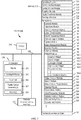
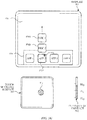
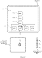
- FIG. 1B is a block diagram illustrating exemplary components for event handling in accordance with some embodiments.
- memory 102 FIG. 1A
- 370 FIG. 3
- event sorter 170 e.g., in operating system 126
- application 136-1 e.g., any of the aforementioned applications 137-151, 155, 380-390.
- Event sorter 170 receives event information and determines the application 136-1 and application view 191 of application 136-1 to which to deliver the event information.
- Event sorter 170 includes event monitor 171 and event dispatcher module 174.
- application 136-1 includes application internal state 192, which indicates the current application view(s) displayed on touch-sensitive display 112 when the application is active or executing.
- device/global internal state 157 is used by event sorter 170 to determine which application(s) is (are) currently active, and application internal state 192 is used by event sorter 170 to determine application views 191 to which to deliver event information.
- application internal state 192 includes additional information, such as one or more of: resume information to be used when application 136-1 resumes execution, user interface state information that indicates information being displayed or that is ready for display by application 136-1, a state queue for enabling the user to go back to a prior state or view of application 136-1, and a redo/undo queue of previous actions taken by the user.
- Event monitor 171 receives event information from peripherals interface 118.
- Event information includes information about a sub-event (e.g., a user touch on touch-sensitive display 112, as part of a multi-touch gesture).
- Peripherals interface 118 transmits information it receives from I/O subsystem 106 or a sensor, such as proximity sensor 166, accelerometer(s) 168, and/or microphone 113 (through audio circuitry 110).
- Information that peripherals interface 118 receives from I/O subsystem 106 includes information from touch-sensitive display 112 or a touch-sensitive surface.
- event monitor 171 sends requests to the peripherals interface 118 at predetermined intervals. In response, peripherals interface 118 transmits event information. In other embodiments, peripherals interface 118 transmits event information only when there is a significant event (e.g., receiving an input above a predetermined noise threshold and/or for more than a predetermined duration).
- event sorter 170 also includes a hit view determination module 172 and/or an active event recognizer determination module 173.
- Hit view determination module 172 provides software procedures for determining where a sub-event has taken place within one or more views when touch-sensitive display 112 displays more than one view. Views are made up of controls and other elements that a user can see on the display.
- the application views (of a respective application) in which a touch is detected optionally correspond to programmatic levels within a programmatic or view hierarchy of the application. For example, the lowest level view in which a touch is detected is, optionally, called the hit view, and the set of events that are recognized as proper inputs are, optionally, determined based, at least in part, on the hit view of the initial touch that begins a touch-based gesture.
- Hit view determination module 172 receives information related to sub-events of a touch-based gesture.
- hit view determination module 172 identifies a hit view as the lowest view in the hierarchy which should handle the sub-event. In most circumstances, the hit view is the lowest level view in which an initiating sub-event occurs (e.g., the first sub-event in the sequence of sub-events that form an event or potential event).
- the hit view typically receives all sub-events related to the same touch or input source for which it was identified as the hit view.
- Active event recognizer determination module 173 determines which view or views within a view hierarchy should receive a particular sequence of sub-events. In some embodiments, active event recognizer determination module 173 determines that only the hit view should receive a particular sequence of sub-events. In other embodiments, active event recognizer determination module 173 determines that all views that include the physical location of a sub-event are actively involved views, and therefore determines that all actively involved views should receive a particular sequence of sub-events. In other embodiments, even if touch sub-events were entirely confined to the area associated with one particular view, views higher in the hierarchy would still remain as actively involved views.
- Event dispatcher module 174 dispatches the event information to an event recognizer (e.g., event recognizer 180). In embodiments including active event recognizer determination module 173, event dispatcher module 174 delivers the event information to an event recognizer determined by active event recognizer determination module 173. In some embodiments, event dispatcher module 174 stores in an event queue the event information, which is retrieved by a respective event receiver 182.
- an event recognizer e.g., event recognizer 180.
- event dispatcher module 174 delivers the event information to an event recognizer determined by active event recognizer determination module 173.
- event dispatcher module 174 stores in an event queue the event information, which is retrieved by a respective event receiver 182.
- operating system 126 includes event sorter 170.
- application 136-1 includes event sorter 170.
- event sorter 170 is a stand-alone module, or a part of another module stored in memory 102, such as contact/motion module 130.
- application 136-1 includes a plurality of event handlers 190 and one or more application views 191, each of which includes instructions for handling touch events that occur within a respective view of the application's user interface.
- Each application view 191 of the application 136-1 includes one or more event recognizers 180.
- a respective application view 191 includes a plurality of event recognizers 180.
- one or more of event recognizers 180 are part of a separate module, such as a user interface kit (not shown) or a higher level object from which application 136-1 inherits methods and other properties.
- a respective event handler 190 includes one or more of: data updater 176, object updater 177, GUI updater 178, and/or event data 179 received from event sorter 170.
- Event handler 190 optionally utilizes or calls data updater 176, object updater 177, or GUI updater 178 to update the application internal state 192.
- one or more of the application views 191 include one or more respective event handlers 190.
- one or more of data updater 176, object updater 177, and GUI updater 178 are included in a respective application view 191.
- a respective event recognizer 180 receives event information (e.g., event data 179) from event sorter 170 and identifies an event from the event information.
- Event recognizer 180 includes event receiver 182 and event comparator 184.
- event recognizer 180 also includes at least a subset of: metadata 183, and event delivery instructions 188 (which optionally include sub-event delivery instructions).
- Event receiver 182 receives event information from event sorter 170.
- the event information includes information about a sub-event, for example, a touch or a touch movement.
- the event information also includes additional information, such as location of the sub-event.
- the event information optionally also includes speed and direction of the sub-event.
- events include rotation of the device from one orientation to another (e.g., from a portrait orientation to a landscape orientation, or vice versa), and the event information includes corresponding information about the current orientation (also called device attitude) of the device.
- Event comparator 184 compares the event information to predefined event or sub-event definitions and, based on the comparison, determines an event or sub-event, or determines or updates the state of an event or sub-event.
- event comparator 184 includes event definitions 186.
- Event definitions 186 contain definitions of events (e.g., predefined sequences of sub-events), for example, event 1 (187-1), event 2 (187-2), and others.
- sub-events in an event (187) include, for example, touch begin, touch end, touch movement, touch cancellation, and multiple touching.
- the definition for event 1 (187-1) is a double tap on a displayed object.
- the double tap for example, comprises a first touch (touch begin) on the displayed object for a predetermined phase, a first liftoff (touch end) for a predetermined phase, a second touch (touch begin) on the displayed object for a predetermined phase, and a second liftoff (touch end) for a predetermined phase.
- the definition for event 2 (187-2) is a dragging on a displayed object.
- the dragging for example, comprises a touch (or contact) on the displayed object for a predetermined phase, a movement of the touch across touch-sensitive display 112, and liftoff of the touch (touch end).
- the event also includes information for one or more associated event handlers 190.
- event definition 187 includes a definition of an event for a respective user-interface object.
- event comparator 184 performs a hit test to determine which user-interface object is associated with a sub-event. For example, in an application view in which three user-interface objects are displayed on touch-sensitive display 112, when a touch is detected on touch-sensitive display 112, event comparator 184 performs a hit test to determine which of the three user-interface objects is associated with the touch (sub-event). If each displayed object is associated with a respective event handler 190, the event comparator uses the result of the hit test to determine which event handler 190 should be activated. For example, event comparator 184 selects an event handler associated with the sub-event and the object triggering the hit test.
- the definition for a respective event (187) also includes delayed actions that delay delivery of the event information until after it has been determined whether the sequence of sub-events does or does not correspond to the event recognizer's event type.
- a respective event recognizer 180 determines that the series of sub-events do not match any of the events in event definitions 186, the respective event recognizer 180 enters an event impossible, event failed, or event ended state, after which it disregards subsequent sub-events of the touch-based gesture. In this situation, other event recognizers, if any, that remain active for the hit view continue to track and process sub-events of an ongoing touch-based gesture.
- a respective event recognizer 180 includes metadata 183 with configurable properties, flags, and/or lists that indicate how the event delivery system should perform sub-event delivery to actively involved event recognizers.
- metadata 183 includes configurable properties, flags, and/or lists that indicate how event recognizers interact, or are enabled to interact, with one another.
- metadata 183 includes configurable properties, flags, and/or lists that indicate whether sub-events are delivered to varying levels in the view or programmatic hierarchy.
- a respective event recognizer 180 activates event handler 190 associated with an event when one or more particular sub-events of an event are recognized.
- a respective event recognizer 180 delivers event information associated with the event to event handler 190. Activating an event handler 190 is distinct from sending (and deferred sending) sub-events to a respective hit view.
- event recognizer 180 throws a flag associated with the recognized event, and event handler 190 associated with the flag catches the flag and performs a predefined process.
- event delivery instructions 188 include sub-event delivery instructions that deliver event information about a sub-event without activating an event handler. Instead, the sub-event delivery instructions deliver event information to event handlers associated with the series of sub-events or to actively involved views. Event handlers associated with the series of sub-events or with actively involved views receive the event information and perform a predetermined process.
- data updater 176 creates and updates data used in application 136-1. For example, data updater 176 updates the telephone number used in contacts module 137, or stores a video file used in video player module.
- object updater 177 creates and updates objects used in application 136-1. For example, object updater 177 creates a new user-interface object or updates the position of a user-interface object.
- GUI updater 178 updates the GUI. For example, GUI updater 178 prepares display information and sends it to graphics module 132 for display on a touch-sensitive display.
- event handler(s) 190 includes or has access to data updater 176, object updater 177, and GUI updater 178.
- data updater 176, object updater 177, and GUI updater 178 are included in a single module of a respective application 136-1 or application view 191. In other embodiments, they are included in two or more software modules.
- event handling of user touches on touch-sensitive displays also applies to other forms of user inputs to operate multifunction devices 100 with input devices, not all of which are initiated on touch screens.
- mouse movement and mouse button presses optionally coordinated with single or multiple keyboard presses or holds; contact movements such as taps, drags, scrolls, etc. on touchpads; pen stylus inputs; movement of the device; oral instructions; detected eye movements; biometric inputs; and/or any combination thereof are optionally utilized as inputs corresponding to sub-events which define an event to be recognized.
- FIG. 2 illustrates a portable multifunction device 100 having a touch screen 112 in accordance with some embodiments.
- the touch screen optionally displays one or more graphics within user interface (UI) 200.
- UI user interface
- a user is enabled to select one or more of the graphics by making a gesture on the graphics, for example, with one or more fingers 202 (not drawn to scale in the figure) or one or more styluses 203 (not drawn to scale in the figure).
- selection of one or more graphics occurs when the user breaks contact with the one or more graphics.
- the gesture optionally includes one or more taps, one or more swipes (from left to right, right to left, upward and/or downward), and/or a rolling of a finger (from right to left, left to right, upward and/or downward) that has made contact with device 100.
- inadvertent contact with a graphic does not select the graphic.
- a swipe gesture that sweeps over an application icon optionally does not select the corresponding application when the gesture corresponding to selection is a tap.
- Device 100 optionally also include one or more physical buttons, such as "home" or menu button 204.
- menu button 204 is, optionally, used to navigate to any application 136 in a set of applications that are, optionally, executed on device 100.
- the menu button is implemented as a soft key in a GUI displayed on touch screen 112.
- device 100 includes touch screen 112, menu button 204, push button 206 for powering the device on/off and locking the device, volume adjustment button(s) 208, subscriber identity module (SIM) card slot 210, headset jack 212, and docking/charging external port 124.
- Push button 206 is, optionally, used to turn the power on/off on the device by depressing the button and holding the button in the depressed state for a predefined time interval; to lock the device by depressing the button and releasing the button before the predefined time interval has elapsed; and/or to unlock the device or initiate an unlock process.
- device 100 also accepts verbal input for activation or deactivation of some functions through microphone 113.
- Device 100 also, optionally, includes one or more contact intensity sensors 165 for detecting intensity of contacts on touch screen 112 and/or one or more tactile output generators 167 for generating tactile outputs for a user of device 100.
- FIG. 3 is a block diagram of an exemplary multifunction device with a display and a touch-sensitive surface in accordance with some embodiments.
- Device 300 need not be portable.
- device 300 is a laptop computer, a desktop computer, a tablet computer, a multimedia player device, a navigation device, an educational device (such as a child's learning toy), a gaming system, or a control device (e.g., a home or industrial controller).
- Device 300 typically includes one or more processing units (CPUs) 310, one or more network or other communications interfaces 360, memory 370, and one or more communication buses 320 for interconnecting these components.
- Communication buses 320 optionally include circuitry (sometimes called a chipset) that interconnects and controls communications between system components.
- Device 300 includes input/output (I/O) interface 330 comprising display 340, which is typically a touch screen display.
- I/O interface 330 also optionally includes a keyboard and/or mouse (or other pointing device) 350 and touchpad 355, tactile output generator 357 for generating tactile outputs on device 300 (e.g., similar to tactile output generator(s) 167 described above with reference to FIG. 1A ), sensors 359 (e.g., optical, acceleration, proximity, touch-sensitive, and/or contact intensity sensors similar to contact intensity sensor(s) 165 described above with reference to FIG. 1A ).
- sensors 359 e.g., optical, acceleration, proximity, touch-sensitive, and/or contact intensity sensors similar to contact intensity sensor(s) 165 described above with reference to FIG. 1A ).
- Memory 370 includes high-speed random access memory, such as DRAM, SRAM, DDR RAM, or other random access solid state memory devices; and optionally includes non-volatile memory, such as one or more magnetic disk storage devices, optical disk storage devices, flash memory devices, or other non-volatile solid state storage devices. Memory 370 optionally includes one or more storage devices remotely located from CPU(s) 310. In some embodiments, memory 370 stores programs, modules, and data structures analogous to the programs, modules, and data structures stored in memory 102 of portable multifunction device 100 ( FIG. 1A ), or a subset thereof. Furthermore, memory 370 optionally stores additional programs, modules, and data structures not present in memory 102 of portable multifunction device 100.
- memory 370 of device 300 optionally stores drawing module 380, presentation module 382, word processing module 384, website creation module 386, disk authoring module 388, and/or spreadsheet module 390, while memory 102 of portable multifunction device 100 ( FIG. 1A ) optionally does not store these modules.
- Each of the above-identified elements in FIG. 3 is, optionally, stored in one or more of the previously mentioned memory devices.
- Each of the above-identified modules corresponds to a set of instructions for performing a function described above.
- the above-identified modules or programs (e.g., sets of instructions) need not be implemented as separate software programs, procedures, or modules, and thus various subsets of these modules are, optionally, combined or otherwise rearranged in various embodiments.
- memory 370 optionally stores a subset of the modules and data structures identified above. Furthermore, memory 370 optionally stores additional modules and data structures not described above.
- FIG. 4A illustrates an exemplary user interface for a menu of applications on portable multifunction device 100 in accordance with some embodiments. Similar user interfaces are, optionally, implemented on device 300.
- user interface 400 includes the following elements, or a subset or superset thereof:
- icon labels illustrated in FIG. 4A are merely exemplary.
- icon 422 for video and music player module 152 is labeled "Music" or "Music Player.”
- Other labels are, optionally, used for various application icons.
- a label for a respective application icon includes a name of an application corresponding to the respective application icon.
- a label for a particular application icon is distinct from a name of an application corresponding to the particular application icon.
- FIG. 4B illustrates an exemplary user interface on a device (e.g., device 300, FIG. 3 ) with a touch-sensitive surface 451 (e.g., a tablet or touchpad 355, FIG. 3 ) that is separate from the display 450 (e.g., touch screen display 112).
- Device 300 also, optionally, includes one or more contact intensity sensors (e.g., one or more of sensors 359) for detecting intensity of contacts on touch-sensitive surface 451 and/or one or more tactile output generators 357 for generating tactile outputs for a user of device 300.
- one or more contact intensity sensors e.g., one or more of sensors 359
- tactile output generators 357 for generating tactile outputs for a user of device 300.
- the device detects inputs on a touch-sensitive surface that is separate from the display, as shown in FIG. 4B .
- the touch-sensitive surface e.g., 451 in FIG. 4B
- the touch-sensitive surface has a primary axis (e.g., 452 in FIG. 4B ) that corresponds to a primary axis (e.g., 453 in FIG. 4B ) on the display (e.g., 450).
- the device detects contacts (e.g., 460 and 462 in FIG.
- finger inputs e.g., finger contacts, finger tap gestures, finger swipe gestures
- one or more of the finger inputs are replaced with input from another input device (e.g., a mouse-based input or stylus input).
- a swipe gesture is, optionally, replaced with a mouse click (e.g., instead of a contact) followed by movement of the cursor along the path of the swipe (e.g., instead of movement of the contact).
- a tap gesture is, optionally, replaced with a mouse click while the cursor is located over the location of the tap gesture (e.g., instead of detection of the contact followed by ceasing to detect the contact).
- multiple user inputs are simultaneously detected, it should be understood that multiple computer mice are, optionally, used simultaneously, or a mouse and finger contacts are, optionally, used simultaneously.
- FIG. 5A illustrates exemplary personal electronic device 500.
- Device 500 includes body 502.
- device 500 can include some or all of the features described with respect to devices 100 and 300 (e.g., FIGS. 1A-4B ).
- device 500 has touch-sensitive display screen 504, hereafter touch screen 504.
- touch screen 504 optionally includes one or more intensity sensors for detecting intensity of contacts (e.g., touches) being applied.
- the one or more intensity sensors of touch screen 504 (or the touch-sensitive surface) can provide output data that represents the intensity of touches.
- the user interface of device 500 can respond to touches based on their intensity, meaning that touches of different intensities can invoke different user interface operations on device 500.
- Exemplary techniques for detecting and processing touch intensity are found, for example, in related applications: International Patent Application Serial No. PCT/US2013/040061, titled “Device, Method, and Graphical User Interface for Displaying User Interface Objects Corresponding to an Application,” filed May 8, 2013 , published as WIPO Publication No. WO/2013/169849 , and International Patent Application Serial No. PCT/US2013/069483, titled “Device, Method, and Graphical User Interface for Transitioning Between Touch Input to Display Output Relationships,” filed November 11, 2013 , published as WIPO Publication No. WO/2014/105276 , each of which is hereby incorporated by reference in their entirety.
- device 500 has one or more input mechanisms 506 and 508.
- Input mechanisms 506 and 508, if included, can be physical. Examples of physical input mechanisms include push buttons and rotatable mechanisms.
- device 500 has one or more attachment mechanisms. Such attachment mechanisms, if included, can permit attachment of device 500 with, for example, hats, eyewear, earrings, necklaces, shirts, jackets, bracelets, watch straps, chains, trousers, belts, shoes, purses, backpacks, and so forth. These attachment mechanisms permit device 500 to be worn by a user.
- FIG. 5B depicts exemplary personal electronic device 500.
- device 500 can include some or all of the components described with respect to FIGS. 1A , 1B , and 3 .
- Device 500 has bus 512 that operatively couples I/O section 514 with one or more computer processors 516 and memory 518.
- I/O section 514 can be connected to display 504, which can have touch-sensitive component 522 and, optionally, intensity sensor 524 (e.g., contact intensity sensor).
- I/O section 514 can be connected with communication unit 530 for receiving application and operating system data, using Wi-Fi, Bluetooth, near field communication (NFC), cellular, and/or other wireless communication techniques.
- Device 500 can include input mechanisms 506 and/or 508.
- Input mechanism 506 is, optionally, a rotatable input device or a depressible and rotatable input device, for example.
- Input mechanism 508 is, optionally, a button, in some examples.
- Input mechanism 508 is, optionally, a microphone, in some examples.
- Personal electronic device 500 optionally includes various sensors, such as GPS sensor 532, accelerometer 534, directional sensor 540 (e.g., compass), gyroscope 536, motion sensor 538, and/or a combination thereof, all of which can be operatively connected to I/O section 514.
- sensors such as GPS sensor 532, accelerometer 534, directional sensor 540 (e.g., compass), gyroscope 536, motion sensor 538, and/or a combination thereof, all of which can be operatively connected to I/O section 514.
- Memory 518 of personal electronic device 500 can include one or more non-transitory computer-readable storage mediums, for storing computer-executable instructions, which, when executed by one or more computer processors 516, for example, can cause the computer processors to perform the techniques described below, including process 700 ( FIGS. 7A-E ).
- a computer-readable storage medium can be any medium that can tangibly contain or store computer-executable instructions for use by or in connection with the instruction execution system, apparatus, or device.
- the storage medium is a transitory computer-readable storage medium.
- the storage medium is a non-transitory computer-readable storage medium.
- the non-transitory computer-readable storage medium can include, but is not limited to, magnetic, optical, and/or semiconductor storages.
- Personal electronic device 500 is not limited to the components and configuration of FIG. 5B , but can include other or additional components in multiple configurations.
- the term "affordance” refers to a user-interactive graphical user interface object that is, optionally, displayed on the display screen of devices 100, 300, and/or 500 ( FIGS. 1A-B , 3 , and 5A-H ).
- an image e.g., icon
- a button e.g., button
- text e.g., hyperlink
- the term "focus selector” refers to an input element that indicates a current part of a user interface with which a user is interacting.
- the cursor acts as a "focus selector” so that when an input (e.g., a press input) is detected on a touch-sensitive surface (e.g., touchpad 355 in FIG. 3 or touch-sensitive surface 451 in FIG. 4B ) while the cursor is over a particular user interface element (e.g., a button, window, slider, or other user interface element), the particular user interface element is adjusted in accordance with the detected input.
- a touch screen display e.g., touch-sensitive display system 112 in FIG.
- a detected contact on the touch screen acts as a "focus selector" so that when an input (e.g., a press input by the contact) is detected on the touch screen display at a location of a particular user interface element (e.g., a button, window, slider, or other user interface element), the particular user interface element is adjusted in accordance with the detected input.
- an input e.g., a press input by the contact
- a particular user interface element e.g., a button, window, slider, or other user interface element
- focus is moved from one region of a user interface to another region of the user interface without corresponding movement of a cursor or movement of a contact on a touch screen display (e.g., by using a tab key or arrow keys to move focus from one button to another button); in these implementations, the focus selector moves in accordance with movement of focus between different regions of the user interface.
- the focus selector is generally the user interface element (or contact on a touch screen display) that is controlled by the user so as to communicate the user's intended interaction with the user interface (e.g., by indicating, to the device, the element of the user interface with which the user is intending to interact).
- a focus selector e.g., a cursor, a contact, or a selection box
- a press input is detected on the touch-sensitive surface (e.g., a touchpad or touch screen) will indicate that the user is intending to activate the respective button (as opposed to other user interface elements shown on a display of the device).
- the term "characteristic intensity" of a contact refers to a characteristic of the contact based on one or more intensities of the contact.
- the characteristic intensity is based on multiple intensity samples.
- the characteristic intensity is, optionally, based on a predefined number of intensity samples, or a set of intensity samples collected during a predetermined time period (e.g., 0.05, 0.1, 0.2, 0.5, 1, 2, 5, 10 seconds) relative to a predefined event (e.g., after detecting the contact, prior to detecting liftoff of the contact, before or after detecting a start of movement of the contact, prior to detecting an end of the contact, before or after detecting an increase in intensity of the contact, and/or before or after detecting a decrease in intensity of the contact).
- a predefined time period e.g., 0.05, 0.1, 0.2, 0.5, 1, 2, 5, 10 seconds
- a characteristic intensity of a contact is, optionally, based on one or more of: a maximum value of the intensities of the contact, a mean value of the intensities of the contact, an average value of the intensities of the contact, a top 10 percentile value of the intensities of the contact, a value at the half maximum of the intensities of the contact, a value at the 90 percent maximum of the intensities of the contact, or the like.
- the duration of the contact is used in determining the characteristic intensity (e.g., when the characteristic intensity is an average of the intensity of the contact over time).
- the characteristic intensity is compared to a set of one or more intensity thresholds to determine whether an operation has been performed by a user.
- the set of one or more intensity thresholds optionally includes a first intensity threshold and a second intensity threshold.
- a contact with a characteristic intensity that does not exceed the first threshold results in a first operation
- a contact with a characteristic intensity that exceeds the first intensity threshold and does not exceed the second intensity threshold results in a second operation
- a contact with a characteristic intensity that exceeds the second threshold results in a third operation.
- a comparison between the characteristic intensity and one or more thresholds is used to determine whether or not to perform one or more operations (e.g., whether to perform a respective operation or forgo performing the respective operation), rather than being used to determine whether to perform a first operation or a second operation.
- FIG. 5C illustrates detecting a plurality of contacts 552A-552E on touch-sensitive display screen 504 with a plurality of intensity sensors 524A-524D.
- FIG. 5C additionally includes intensity diagrams that show the current intensity measurements of the intensity sensors 524A-524D relative to units of intensity.
- the intensity measurements of intensity sensors 524A and 524D are each 9 units of intensity
- the intensity measurements of intensity sensors 524B and 524C are each 7 units of intensity.
- an aggregate intensity is the sum of the intensity measurements of the plurality of intensity sensors 524A-524D, which in this example is 32 intensity units.
- each contact is assigned a respective intensity that is a portion of the aggregate intensity.
- each of contacts 552A, 552B, and 552E are assigned an intensity of contact of 8 intensity units of the aggregate intensity
- each of contacts 552C and 552D are assigned an intensity of contact of 4 intensity units of the aggregate intensity.
- Ij A ⁇ (Dj/ ⁇ Di)
- Dj is the distance of the respective contact j to the center of force
- the operations described with reference to FIGS. 5C-5D can be performed using an electronic device similar or identical to device 100, 300, or 500.
- a characteristic intensity of a contact is based on one or more intensities of the contact.
- the intensity sensors are used to determine a single characteristic intensity (e.g., a single characteristic intensity of a single contact). It should be noted that the intensity diagrams are not part of a displayed user interface, but are included in FIGS. 5C-5D to aid the reader.
- a portion of a gesture is identified for purposes of determining a characteristic intensity.
- a touch-sensitive surface optionally receives a continuous swipe contact transitioning from a start location and reaching an end location, at which point the intensity of the contact increases.
- the characteristic intensity of the contact at the end location is, optionally, based on only a portion of the continuous swipe contact, and not the entire swipe contact (e.g., only the portion of the swipe contact at the end location).
- a smoothing algorithm is, optionally, applied to the intensities of the swipe contact prior to determining the characteristic intensity of the contact.
- the smoothing algorithm optionally includes one or more of: an unweighted sliding-average smoothing algorithm, a triangular smoothing algorithm, a median filter smoothing algorithm, and/or an exponential smoothing algorithm.
- these smoothing algorithms eliminate narrow spikes or dips in the intensities of the swipe contact for purposes of determining a characteristic intensity.
- the intensity of a contact on the touch-sensitive surface is, optionally, characterized relative to one or more intensity thresholds, such as a contact-detection intensity threshold, a light press intensity threshold, a deep press intensity threshold, and/or one or more other intensity thresholds.
- the light press intensity threshold corresponds to an intensity at which the device will perform operations typically associated with clicking a button of a physical mouse or a trackpad.
- the deep press intensity threshold corresponds to an intensity at which the device will perform operations that are different from operations typically associated with clicking a button of a physical mouse or a trackpad.
- the device when a contact is detected with a characteristic intensity below the light press intensity threshold (e.g., and above a nominal contact-detection intensity threshold below which the contact is no longer detected), the device will move a focus selector in accordance with movement of the contact on the touch-sensitive surface without performing an operation associated with the light press intensity threshold or the deep press intensity threshold.
- a characteristic intensity below the light press intensity threshold e.g., and above a nominal contact-detection intensity threshold below which the contact is no longer detected
- these intensity thresholds are consistent between different sets of user interface figures.
- An increase of characteristic intensity of the contact from an intensity below the light press intensity threshold to an intensity between the light press intensity threshold and the deep press intensity threshold is sometimes referred to as a "light press” input.
- An increase of characteristic intensity of the contact from an intensity below the deep press intensity threshold to an intensity above the deep press intensity threshold is sometimes referred to as a "deep press” input.
- An increase of characteristic intensity of the contact from an intensity below the contact-detection intensity threshold to an intensity between the contact-detection intensity threshold and the light press intensity threshold is sometimes referred to as detecting the contact on the touch-surface.
- a decrease of characteristic intensity of the contact from an intensity above the contact-detection intensity threshold to an intensity below the contact-detection intensity threshold is sometimes referred to as detecting liftoff of the contact from the touch-surface.
- the contact-detection intensity threshold is zero. In some embodiments, the contact-detection intensity threshold is greater than zero.
- one or more operations are performed in response to detecting a gesture that includes a respective press input or in response to detecting the respective press input performed with a respective contact (or a plurality of contacts), where the respective press input is detected based at least in part on detecting an increase in intensity of the contact (or plurality of contacts) above a press-input intensity threshold.
- the respective operation is performed in response to detecting the increase in intensity of the respective contact above the press-input intensity threshold (e.g., a "down stroke" of the respective press input).
- the press input includes an increase in intensity of the respective contact above the press-input intensity threshold and a subsequent decrease in intensity of the contact below the press-input intensity threshold, and the respective operation is performed in response to detecting the subsequent decrease in intensity of the respective contact below the press-input threshold (e.g., an "up stroke" of the respective press input).
- FIGS. 5E-5H illustrate detection of a gesture that includes a press input that corresponds to an increase in intensity of a contact 562 from an intensity below a light press intensity threshold (e.g., "IT L ”) in FIG. 5E , to an intensity above a deep press intensity threshold (e.g., "IT D ”) in FIG. 5H .
- the gesture performed with contact 562 is detected on touch-sensitive surface 560 while cursor 576 is displayed over application icon 572B corresponding to App 2, on a displayed user interface 570 that includes application icons 572A-572D displayed in predefined region 574.
- the gesture is detected on touch-sensitive display 504.
- the intensity sensors detect the intensity of contacts on touch-sensitive surface 560.
- the device determines that the intensity of contact 562 peaked above the deep press intensity threshold (e.g., "IT D ").
- Contact 562 is maintained on touch-sensitive surface 560.
- reduced-scale representations 578A-578C e.g., thumbnails
- the intensity which is compared to the one or more intensity thresholds, is the characteristic intensity of a contact. It should be noted that the intensity diagram for contact 562 is not part of a displayed user interface, but is included in FIGS. 5E-5H to aid the reader.
- the display of representations 578A-578C includes an animation.
- representation 578A is initially displayed in proximity of application icon 572B, as shown in FIG. 5F .
- representation 578A moves upward and representation 578B is displayed in proximity of application icon 572B, as shown in FIG. 5G .
- representations 578A moves upward, 578B moves upward toward representation 578A, and representation 578C is displayed in proximity of application icon 572B, as shown in FIG. 5H .
- Representations 578A-578C form an array above icon 572B.
- the animation progresses in accordance with an intensity of contact 562, as shown in FIGS.
- the intensity, on which the progress of the animation is based is the characteristic intensity of the contact.
- the operations described with reference to FIGS. 5E-5H can be performed using an electronic device similar or identical to device 100, 300, or 500.
- the device employs intensity hysteresis to avoid accidental inputs sometimes termed "jitter," where the device defines or selects a hysteresis intensity threshold with a predefined relationship to the press-input intensity threshold (e.g., the hysteresis intensity threshold is X intensity units lower than the press-input intensity threshold or the hysteresis intensity threshold is 75%, 90%, or some reasonable proportion of the press-input intensity threshold).
- the hysteresis intensity threshold is X intensity units lower than the press-input intensity threshold or the hysteresis intensity threshold is 75%, 90%, or some reasonable proportion of the press-input intensity threshold.
- the press input includes an increase in intensity of the respective contact above the press-input intensity threshold and a subsequent decrease in intensity of the contact below the hysteresis intensity threshold that corresponds to the press-input intensity threshold, and the respective operation is performed in response to detecting the subsequent decrease in intensity of the respective contact below the hysteresis intensity threshold (e.g., an "up stroke" of the respective press input).
- the press input is detected only when the device detects an increase in intensity of the contact from an intensity at or below the hysteresis intensity threshold to an intensity at or above the press-input intensity threshold and, optionally, a subsequent decrease in intensity of the contact to an intensity at or below the hysteresis intensity, and the respective operation is performed in response to detecting the press input (e.g., the increase in intensity of the contact or the decrease in intensity of the contact, depending on the circumstances).
- the descriptions of operations performed in response to a press input associated with a press-input intensity threshold or in response to a gesture including the press input are, optionally, triggered in response to detecting either: an increase in intensity of a contact above the press-input intensity threshold, an increase in intensity of a contact from an intensity below the hysteresis intensity threshold to an intensity above the press-input intensity threshold, a decrease in intensity of the contact below the press-input intensity threshold, and/or a decrease in intensity of the contact below the hysteresis intensity threshold corresponding to the press-input intensity threshold.
- the operation is, optionally, performed in response to detecting a decrease in intensity of the contact below a hysteresis intensity threshold corresponding to, and lower than, the press-input intensity threshold.
- an "installed application” refers to a software application that has been downloaded onto an electronic device (e.g., devices 100, 300, and/or 500) and is ready to be launched (e.g., become opened) on the device.
- a downloaded application becomes an installed application by way of an installation program that extracts program portions from a downloaded package and integrates the extracted portions with the operating system of the computer system.
- open application or "executing application” refer to a software application with retained state information (e.g., as part of device/global internal state 157 and/or application internal state 192).
- An open or executing application is, optionally, any one of the following types of applications:
- closing an application refers to software applications without retained state information (e.g., state information for closed applications is not stored in a memory of the device). Accordingly, closing an application includes stopping and/or removing application processes for the application and removing state information for the application from the memory of the device. Generally, opening a second application while in a first application does not close the first application. When the second application is displayed and the first application ceases to be displayed, the first application becomes a background application.
- UI user interfaces
- portable multifunction device 100 such as portable multifunction device 100, device 300, or device 500.
- FIGS. 6A-Z illustrate exemplary devices and user interfaces for managing input mechanisms, in accordance with some embodiments.
- the user interfaces in these figures are used to illustrate the processes described below, including the processes in FIGS. 7A-E .
- FIG. 6A illustrates an exemplary electronic device 600 with one or more input mechanisms.
- the electronic device 600 is a smartwatch and includes a first input mechanism (e.g., touch-sensitive display 602), a second input mechanism (e.g., rotatable input mechanism 608), and a third input mechanism (e.g., physical button 612).
- the electronic device displays, via the touch-sensitive display 602, a home user interface (e.g., 630).
- the home user interface 630 includes a number of affordances including a time affordance (e.g., 603; "10:09”), a temperature affordance (e.g., 604; "72°"), and calendar reminder affordance (e.g., 606; "12:00-1:00 LUNCH MEETING").
- a time affordance e.g., 603; "10:09
- a temperature affordance e.g., 604; "72°”
- calendar reminder affordance e.g., 606; "12:00-1:00 LUNCH MEETING"
- the various input mechanisms of the electronic device are associated with different input modalities.
- the first input mechanism e.g., touch-sensitive display 602 of electronic device 600 is associated with a first input modality (e.g., tap/touch inputs detected via capacitive touch detection).
- the second input mechanism e.g., rotatable input mechanism 608 is associated with a second input modality different from the first input modality.
- the second input mechanism is associated with a second input modality (e.g., rotational inputs detected via mechanical actuation detection) that is not based on capacitive touch detection.
- the third input mechanism is associated with a third input modality (e.g., push inputs detected via mechanical actuation detection) that is not based on capacitive touch detection.
- the electronic device 600 has multiple modes of operation.
- a given mode of operation can dictate whether each of the various input mechanisms (touch-sensitive display 602, rotatable input mechanism 608, physical button 612) of the electronic device is disabled or enabled for user input, as described in detail herein. Further, the various input mechanisms, when disabled for user input, can respond differently to the detection of a respective input, as described in detail herein.
- the electronic device 600 is in a second mode of operation (e.g., normal mode).
- the input mechanisms of the electronic device 600 including the touch-sensitive display 602, the rotatable input mechanism 608, and the physical button 612, are enabled for user input.
- the electronic device 600 detects, via the enabled first input mechanism (e.g., touch-sensitive display 602), an input (e.g., a tap input 605).
- the tap input 605 is at a location that corresponds to the calendar reminder affordance (e.g., 606) and is indicative of a selection (or activation) of the calendar reminder affordance (e.g., 606).
- the electronic device 600 in response to detecting the input (e.g., tap input 605) via the enabled first input mechanism, provides an output indicating that the input (e.g., a tap input 605) has been detected.
- the detected input e.g., tap input 605
- an affordance e.g., calendar reminder affordance 606
- providing an output includes updating display of content on the touch-sensitive display 602 (e.g., displaying calendar detail user interface 610).
- the electronic device 600 when the input (e.g., a tap input 605) is detected when the touch-sensitive display 602 is inactive (e.g., not providing visual information), the electronic device 600 activates the touch-sensitive display 602 (e.g., providing visual information via the touch-sensitive display 602).
- the electronic device 600 responds to tap input 605 by displaying further details (e.g., location information) regarding the calendar event associated with the calendar reminder affordance 606 of FIG. 6B .
- the electronic device 600 is in the second mode of operation (e.g., normal mode), in which the third input mechanism (e.g., physical button 612) are enabled for user input, as discussed above.
- the electronic device 600 detects, via the enabled third input mechanism (e.g., physical button 612), an input (e.g., a push input 613).
- the electronic device 600 detects the push input 613 when the touch-sensitive display 602 displays a "home" or home user interface.
- the electronic device 600 interprets the push input 613 as indicative of a request to access (or activate) a particular user interface (e.g., menu 614 depicted in FIG. 6E ).
- the electronic device 600 in response to detecting the input (e.g., push input 613) via the enabled third input mechanism (e.g., physical button 612), the electronic device 600 provides an output indicating that the input has been detected.
- the detected input e.g., tap input 613
- a user interface e.g., menu 614
- providing an output includes updating display of content on the touch-sensitive display 602 (e.g., by displaying menu 614).
- the electronic device 600 when the input (e.g., push input 613) is detected via the third input mechanism (e.g., physical button 612) when the touch-sensitive display 602 is inactive (e.g., not providing visual information), the electronic device 600 activates the touch-sensitive display 602 (e.g., providing visual information via the touch-sensitive display 602) in response to detection of the input.
- the electronic device 600 responds to push input 613 by displaying a menu of contacts (including, for example, contact information associated with contact Jane Doe).
- FIG. 6F illustrates an exemplary user scenario where transitioning an electronic device (e.g., 600) from the second mode (e.g., normal mode) into a different/first mode (e.g., special lock mode) is desirable in order to minimize detection and/or processing of inadvertent inputs at various input mechanisms.
- user 601 wears personal device 600 and is about to enter a pool to start a swimming session. Anticipating that the personal device will come in contact with water during the workout session, user 601 provides appropriate input(s) to put the personal device into a special lock mode.
- the special lock mode one or more input mechanisms of personal device are disabled for user input so as to minimize detection and/or processing of inputs triggered by the device's contact with water.
- a disabled touch-sensitive display of the electronic device 600 does not provide any output in response to force and/or pressure exerted by water on the capacitive touch-sensitive display. Exemplary behaviors of various disabled input mechanisms in the special lock mode are provided herein.
- the electronic device 600 receives an input indicative of a request to enter the first mode (e.g., special lock mode).
- the electronic device 600 displays, via touch-sensitive display 602, a control panel user interface 616, which includes a number of setting affordances including a first mode entering affordance (e.g., 618).
- the input indicative of a request to enter the first mode is a tap input (e.g., 619) at a location that corresponds to the first mode entering affordance (e.g., 618).
- the electronic device 600 in response to receiving the input (e.g., tap input 619) indicative of a request to enter the first mode (e.g., special lock mode), transitions from the second mode (e.g., normal mode) into the first mode (e.g., special lock mode). In some example, after transitioning into the first mode (e.g., special lock mode), the electronic device 600 displays an educational user interface 620 to indicate that the electronic device is in the first mode (e.g., special lock mode). In the depicted example, the educational user interface 602 includes a graphical component (e.g., water-droplet icon 622) and a textual component (e.g., message 624).
- a graphical component e.g., water-droplet icon 622
- a textual component e.g., message 624
- the textual component includes explanation(s) of the first mode of operation, instruction(s) for transitioning the electronic device back into the second mode (e.g., normal mode), and/or introduction(s) of related features of the electronic device 600.
- message 624 includes an instruction for transitioning the electronic device back into the second mode ("TURN DIGITAL CROWN TO UNLOCK") and describes a water-expelling feature of the electronic device 600 ("TURN DIGITAL CROWN TO ... EJECT WATER"). The water-expelling feature is discussed in more detail below.
- the electronic device 600 displays the educational user interface 620 for a predefined period of time. In some examples, the electronic device 600 displays the educational user interface 620 only after the electronic device transitions into the first mode (e.g., special lock mode) under particular circumstances (e.g., for the first time since the activation of electronic device 600, for the first time during a user session, for the first time since the pairing the electronic device 600 to a different electronic device).
- the first mode e.g., special lock mode
- the electronic device 600 displays, via touch-sensitive display 602, a user interface including an indicator (e.g., 626) associated with the first mode.
- the indicator 626 is an icon in the shape of a water droplet and is displayed toward the top portion of the touch-sensitive display 602.
- the electronic device 600 displays a user interface previously displayed before transition into the first mode occurs.
- the electronic device 600 displays, via touch-sensitive display 602, home user interface 630 in addition to the indicator 626.
- the home user interface 630 was previously displayed before the user provided the input indicative of a request to enter the first mode (e.g., tap input 619 on control panel user interface 616, depicted in FIG. 6G ).
- the electronic device 600 displays a default user interface.
- the electronic device 600 displays a user interface based on user preferences. In some examples, after the electronic device transitions from the second mode to the first mode, the electronic device 600 inactivates the display (e.g., 602).
- the first input mechanism e.g., touch-sensitive display 602 is disabled for user input (e.g., a tap input 628).
- the electronic device while the electronic device 600 is in the first mode, the electronic device foregoes detecting user input (e.g., tap input 628) via the disabled first input mechanism (e.g., touch-sensitive display 602) altogether.
- the hardware e.g., circuitry
- the electronic device 600 while the electronic device 600 is in the first mode (e.g., special lock mode), the electronic device detects user input (e.g., tap input 628) via the disabled first input mechanism (e.g., for logging purposes), but foregoes providing an output indicating that the input has been detected.
- user input e.g., tap input 628
- the disabled first input mechanism e.g., for logging purposes
- the electronic device 600 after detecting the input (e.g., tap input 628) via the disabled first input mechanism (e.g., touch-sensitive display 602), the electronic device 600 foregoes providing an output indicating that the input has been detected.
- the detected input e.g., tap input 628
- the electronic device 600 foregoes updating display of content on the touch-sensitive display 602 (e.g., foregoes displaying calendar detail user interface 610 as depicted in FIG. 6C ).
- the electronic device 600 when the input (e.g., a tap input 628) is detected when the touch-sensitive display 602 is inactive (e.g., not providing visual information), the electronic device 600 foregoes activating the touch-sensitive display 602 (e.g., forgoes providing visual information via the touch-sensitive display 602).
- the input e.g., a tap input 628
- the electronic device 600 foregoes activating the touch-sensitive display 602 (e.g., forgoes providing visual information via the touch-sensitive display 602).
- the third input mechanism e.g., physical button 612
- the electronic device while the electronic device 600 is in the first mode, the third input mechanism (e.g., physical button 612) is disabled for user input (e.g., push input 632).
- the electronic device while the electronic device 600 is in the first mode, the electronic device foregoes detecting user input (e.g., push input 632) via the disabled third input mechanism (e.g., physical button 612) altogether.
- the hardware e.g., circuitry
- the electronic device 600 while the electronic device 600 is in the first mode (e.g., special lock mode), the electronic device detects user input (e.g., push input 632) via the disabled third input mechanism but foregoes performing the functionalities (e.g., displaying menu 614 in response to push input 613 as depicted in FIG. 6E ) it would otherwise perform had the electronic device 600 not been in the first mode.
- user input e.g., push input 632
- the functionalities e.g., displaying menu 614 in response to push input 613 as depicted in FIG. 6E
- the electronic device 600 in response to detecting the input (e.g., push input 632) via the third input mechanism (e.g., physical button 612), the electronic device 600 displays, on the touch-sensitive display 602, a user interface indicating that the electronic device is in the first mode (e.g., special lock mode).
- the user interface is identical to the educational user interface 620, which includes a graphical component (e.g., 622) and a textual component (e.g., 624), as described above with respect to FIG. 6H .
- the electronic device 600 displays the user interface (e.g., educational user interface 620) in response to the detection of an input via the third input mechanism only for a predefined period of time.
- the electronic device 600 foregoes displaying the educational user interface 620 and displays the user interface (e.g. home user interface 630) that was previously displayed before the user provided the input.
- the electronic device 600 foregoes displaying the educational user interface 620 and deactivates the display (e.g., 602).
- the electronic device 600 while the electronic device 600 is in the first mode (e.g., special lock mode), the electronic device detects an input (e.g., rotational input 634) via the second input mechanism (e.g., rotational input mechanism 608). In some examples, while continuing to detect the input (e.g., rotational input 634) via the second input mechanism, the electronic device 600 provides an output (e.g., a visual output, a tactile output, or an audio output, or a combination thereof) indicative of an ongoing transition from the first mode (e.g., special lock mode) into the second mode (e.g., normal mode). In some examples, the output indicative of an ongoing transition is an animation. In the depicted example in FIG. 6O , the electronic device 600 starts the playing of the animation by displaying, via touch-sensitive display 602, the educational user interface 620 including a graphical component (e.g., 622) and a textual component (e.g., 624).
- an input e.g., rotational input
- the electronic device 600 only provides an output indicative of an ongoing transition after determining that the input (e.g., rotational input 634) meets an initial set of predefined criteria.
- the initial set of criteria represents a threshold for initiating (or providing an indication of initiating) a transition from the first mode to the second mode.
- the electronic device continues to detect the input (e.g., rotational input 634) detected via the second input mechanism (e.g., rotational input mechanism 608), the electronic device determines whether one or more characteristics of the rotation of the second input mechanism meet the initial set of predefined criteria.
- the electronic device In accordance with a determination that the one or more characteristics of the input (e.g., rotational input 634) meet the initial set of predefined criteria, the electronic device provides an output indicative of an ongoing transition from the first mode to the second mode (e.g., an animation that begins with educational user interface 630). In accordance with a determination that the one or more characteristics of the input (e.g., rotational input 634) does not meet the initial set of predefined criteria, the electronic device does not (or foregoes) providing the output indicative of an ongoing transition from the first mode to the second mode.
- the electronic device does not (or foregoes) providing the output indicative of an ongoing transition from the first mode to the second mode.
- the one or more characteristics of the rotation include a speed of the input (e.g., rotational input 634), a duration of the input (e.g., rotational input 634), a direction of the input (e.g., rotational input 634), a rotational distance of the input (e.g., rotational input 634), a magnitude of the input (e.g., rotational input 634), or a combination thereof.
- the initial set of predefined criteria includes a threshold speed, a threshold duration, a predefined direction, a threshold distance, a threshold magnitude, or a combination thereof.
- the electronic device 600 continues to provide the output indicative of an ongoing transition from the first mode to the second mode.
- the electronic device 600 displays the animation of an expanding water droplet (as illustrated by graphical components 636 and 638).
- the electronic device 600 displays the animation of a fading textual component 624 (fading not depicted in FIGS. 6P and 6Q ).
- the electronic device After detecting the input (e.g., rotational input 634) via the second input mechanism (e.g., rotational input mechanism 608), the electronic device determines whether one or more characteristics of the input meet a set of predefined criteria (e.g., different from the initial set of predefined criteria).
- the set of predefined criteria represents a threshold for transitioning the electronic device from the first mode (e.g., special lock mode) into the second mode (e.g., normal mode).
- the electronic device 600 determines whether one or more characteristics of the rotation of the second input mechanism meet the set of predefined criteria.
- the electronic device 600 detects the input (e.g., rotational input 634) via the second input mechanism (e.g., rotational input mechanism 608). Second, the electronic device 600 determines whether one or more characteristics of the input meet a set of predefined criteria. Mere detection of the input via the second input mechanism (which could be triggered by, e.g., contact with water) is insufficient for triggering the transition into the second mode.
- the input e.g., rotational input 634
- the second input mechanism e.g., rotational input mechanism 608
- the one or more characteristics of the rotation include a speed of the input (e.g., rotational input 634), a duration of the input (e.g., rotational input 634), a direction of the input (e.g., rotational input 634), a rotational distance of the input (e.g., rotational input 634), a magnitude of the input (e.g., rotational input 634), or a combination thereof.
- the set of predefined criteria includes a threshold speed (e.g., larger than that of the initial set of predefined criteria), a threshold duration (e.g., larger than that of the initial set of predefined criteria), a predefined direction, a threshold distance (e.g., larger than that of the initial set of predefined criteria), a threshold magnitude (e.g., larger than that of the initial set of predefined criteria), or a combination thereof.
- the set of predefined criteria is different from the initial set of predefined criteria.
- the electronic device 600 transitions into the second mode (e.g., normal mode).
- the electronic device 600 provides an output (e.g., a visual output, a tactile output, or an audio output, or a combination thereof) indicative of a successful transition from the first mode to the second mode.
- the output includes an animation of a bursting water droplet 640 and a textual message 642 ("UNLOCKED").
- the electronic device 600 displays the animation for a predefined period of time.
- the electronic device 600 has a water-expelling feature to eject water from a speaker of the electronic device using sound emission.
- the electronic device 600 emits a sound (e.g., sound 650) via the speaker of the electronic device.
- the sound e.g., 650 is configured to expel liquid from the speaker of the electronic device.
- At least a portion of the sound (e.g., 650) has a predefined frequency or a predefined range of frequencies sufficient to expel water from the speaker. In some examples, the sound (e.g., 650) has a predefined duration.
- the electronic device while emitting the sound (e.g., 650), the electronic device simultaneously provides the output (e.g., a visual output, a tactile output, or an audio output) indicative of successful transition from the first mode to the second mode (e.g. an animation of a bursting water droplet).
- the electronic device 600 emits the sound (e.g., 650) via the speaker while displaying the animation of bursting water droplet via the display (e.g., 602).
- the electronic device 600 displays a message about the water expelling feature (e.g., "TURN DIGITAL CROWN TO UNLOCK AND EJECT WATER").
- the message is part of the user interface displayed when the electronic device 600 transitions into the first mode, described with respect to FIG. 6H .
- the message is as part of the user interface (e.g., 620) displayed in response to an input (e.g., push input 632) detected via the third input mechanism (e.g. physical button 612), described with respect to FIG. 6M .
- the message is part of the user interface (e.g., 620) displayed in response to an input (e.g., rotational input 634) detected via the second input mechanism (e.g. rotational input mechanism 608), described with respect to FIG. 6O .
- an input e.g., rotational input 634
- the second input mechanism e.g. rotational input mechanism 608
- the electronic device 600 displays a user interface that does not include an indicator (e.g., 626) associated with the first mode.
- an indicator e.g., 626
- the electronic device 600 displays a user interface previously displayed before the electronic devices transitioned into the first mode (e.g., the user interface displayed before the user provides an input to launch control panel user interface 619).
- the electronic device 600 displays a user interface previously displayed while the electronic device was in the first mode.
- the electronic device 600 displays, via touch-sensitive display 602, home user interface 630. The home user interface 630 was displayed while the electronic device was in the first mode before the user provided the rotational input 634.
- the electronic device 600 displays a default user interface. In some examples, after the electronic device transitions from the first mode to the second mode, the electronic device 600 displays a user interface based on user preferences.
- the electronic device 600 In accordance with (or in response to) a determination that the one or more characteristics of the input (e.g., rotational input 634) detected via the second input mechanism do not meet the set of predefined criteria, the electronic device 600 remains in the first mode and foregoes transitioning into the second mode. For example, if the rotational input 634 is terminated before reaching a threshold rotational distance, the electronic device 600 forgoes the transitioning into the second mode.
- the electronic device provides an output indicative of a failed transition from the first mode to the second mode. For example, the electronic device 600 displays a reversal of the output indicative of an ongoing transition as described with respect to FIGS. 6O-Q (e.g., animation of a shrinking water droplet).
- the first input mechanism e.g., touch-sensitive display 602
- the electronic device 600 detects, via the enabled first input mechanism, an input (e.g., tap input 652).
- the tap input 652 is at a location that corresponds to the calendar reminder affordance (e.g., 606) and is indicative of a selection (or activation) of the calendar reminder affordance (e.g., 606).
- the electronic device 600 in response to detecting the input (e.g., tap input 652) via the enabled first input mechanism, the electronic device 600 provides an output indicating that the input (e.g., a tap input 652) has been detected (e.g., by displaying calendar detail user interface 610), similar to the operation of the electronic device 600 as depicted in FIGS. 6B and 6C .
- FIGS. 6V-6Z provide additional exemplary user interfaces for providing the special lock mode at electronic device 600.
- the electronic device 600 displays, via the display (touch-sensitive display 602), a swimming user interface 654.
- the swimming user interface 654 is part of a workout-related application of the electronic device 600.
- the swimming user interface 654 provides information relating to an ongoing workout session (e.g., a swimming session), including progress indicator 656, time value 658, calorie value 660, and lap value 662.
- the electronic device 600 detects, via the first input mechanism (touch-sensitive display 602), an input indicative of a request to display a workout setting user interface.
- the input comprises a finger swipe gesture (e.g., 664).
- the input comprises a press input having a predefined intensity.
- the electronic device 600 displays the workout setting user interface 666.
- the workout setting user interface provides a number of workout setting affordances, including a first mode entering affordance 668.
- the first mode entering affordance 668 includes an icon in the shape of a water droplet.
- the icon associated with the first mode entering affordance 668 is different from the icon associated with the first mode entering affordance 618 of control panel user interface 616, described with respect to FIG. 6G .
- the electronic device 600 detects, via the first input mechanism (touch-sensitive display 602), an input (e.g., tap input 670) indicative of a request to transition the electronic device into the first mode (e.g., special lock mode).
- the electronic device 600 provides an indication that the first mode entering affordance 666 has been selected by updating the display of the first mode entering affordance 668.
- the electronic device 600 displays a grayed out version of the icon associated with the first mode entering affordance 668.
- the electronic device 600 updates the icon associated with the first mode entering affordance with a different icon (e.g., in the shape of a lock).
- the electronic device 600 transitions into the first mode (e.g., special lock mode).
- the electronic device 600 switches the display of touch-sensitive display 602 from the workout setting user interface 666 to the swimming user interface 654.
- the swimming user interface 654 includes an indicator (e.g., 626) associated with the first mode.
- a transition of the electronic device 600 from the second mode (e.g. normal mode) into the first mode only disable a predefined set of functionalities but does not affect other functionalities/operations of the electronic device.
- current operations by active applications and/or background applications of the electronic device e.g., playing music, providing notifications, tracking ongoing workout session
- the electronic device 600 continues to track the ongoing swimming session (e.g., by updating progress indicator 656 and time value 658).
- the first mode of operation can be activated by a variety of input mechanisms (visual, tactile, audio, or a combination thereof) via a variety of user interfaces. While the electronic device is in the first mode (e.g., special lock mode), a variety of input mechanisms can be disabled for user input. Further, the various disabled input mechanisms can respond differently to the detection of a respective user input, as illustrated above with respect to the first input mechanism, the second input mechanism, and the third input mechanisms ( FIGS. 6J-O ).
- FIGS. 7A-E provide a flow diagram illustrating a method for managing input mechanisms using an electronic device in accordance with some embodiments.
- Method 700 is performed at a device (e.g., 100, 300, 500, and 600) with a first input mechanism, a second input mechanism, and optionally, a third input mechanism, a display, and a speaker.
- the first input mechanism and the display are the same unit.
- Some operations in method 700 are, optionally, combined, the order of some operations is, optionally, changed, and some operations are, optionally, omitted.
- the electronic device e.g., 600 is in a first mode (e.g., special lock mode).
- the first input mechanism e.g., touch-sensitive display 602 of the electronic device is disabled for user input in the first mode (e.g., special lock mode).
- disabling one or more input mechanism minimizes detection and/or processing of inputs that are not intended by the user (e.g., unintentional inputs caused by the action of water on capacitive touch screens). By doing so, the accuracy of the machine-human interface is improved. Moreover, doing so conserves device energy, which in battery-operated devices, is of particular importance.
- the electronic device detects an input (e.g., rotational input 634) via the second input mechanism (rotational input mechanism 608).
- detecting the input (e.g., rotational input 634) via the second input mechanism (e.g., rotational input mechanism 608) comprises detecting a rotation of the second input mechanism (rotational input mechanism 608).
- the first input mechanism (e.g., touch-sensitive display 602) of electronic device 600 is associated with a first input modality (e.g., tap/touch inputs detected via capacitive touch detection), and the second input mechanism (e.g., rotatable input mechanism 608) is associated with a second input modality different from the first input modality.
- the second input mechanism is associated with an input modality (e.g., rotational inputs detected via mechanical actuation detection) that is not based on capacitive touch detection.
- input detection via the second input mechanism is less likely to be triggered by environmental factors such as water than input detection via the first input mechanism (e.g., capacitive touch screen).
- the second input mechanism is less likely to be triggered by environmental factors such as water than input detection via the first input mechanism (e.g., capacitive touch screen).
- the second input mechanism is a rotatable input mechanism (e.g., rotational input mechanism 608).
- the first input mechanism is a touch-sensitive display (e.g., touch-sensitive display 602).
- the electronic device determines whether one or more characteristics of the input (e.g., rotational input 634) detected via the second input mechanism (e.g., rotational input mechanism 608) meet a set of predefined criteria.
- the electronic device detects (e.g., at block 704) the input (e.g., rotational input 634) via the second input mechanism (e.g., rotational input mechanism 608).
- the electronic device determines whether one or more characteristics of the input meet a set of predefined criteria. Mere detection of the input via the second input mechanism (which could be triggered by, e.g., contact with water or brief, unintentional user action) is insufficient for triggering the transition into the second mode. By doing so, the likelihood that mode transition is triggered by environmental factors (e.g., water) is minimized and the accuracy of the machine-human interface is improved.
- environmental factors e.g., water
- the detected input is a rotation of the second input mechanism (e.g., rotational input mechanism 608).
- the electronic device e.g., 600
- determines whether one or more characteristics of the rotation of the second input mechanism e.g., rotational input mechanism 608) meet the set of predefined criteria.
- the one or more characteristics of the rotation includes a speed of the rotation, a duration of the rotation, a direction of the rotation, a magnitude of the rotation, or a combination thereof.
- the set of predefined criteria includes a threshold speed, a threshold duration, a predefined direction, a threshold magnitude, or a combination thereof.
- the set of predefined criteria is a first set of predefined criteria.
- the electronic device e.g., 600 determines whether one or more characteristics of the rotation of the second input mechanism (e.g., rotational input mechanism 608) meet a second set of predefined criteria different from the first set of predefined criteria.
- the one or more characteristics of the rotation includes a speed of the rotation, a duration of the rotation, a direction of the rotation, a magnitude of the rotation, or a combination thereof.
- the second set of predefined criteria includes a threshold speed smaller than that of the first set of predefined criteria, a threshold duration smaller than that of the first set of predefined criteria, a threshold magnitude smaller than that of the first set of predefined criteria, or a combination thereof.
- the electronic device in accordance with a determination that the one or more characteristics of the rotation meet the second set of predefined criteria, provides an output indicative of an ongoing transition from the first mode (e.g., special lock mode) to the second mode (e.g., normal mode).
- the output indicative of an ongoing transition from the first mode (e.g., special lock mode) to the second mode (e.g., normal mode) includes a display of an animation of an expanding water droplet (e.g., as illustrated by 622, 636, and 638).
- the output indicative of an ongoing transition reduces the number of failed attempts to transition between modes by providing affirmation to the user and prompting the user to sustain the interaction (e.g., rotation of rotational input mechanism). By doing so, the accuracy of the machine-human interface is improved. Moreover, doing so conserves device energy, which in battery-operated devices, is of particular importance.
- the electronic device in accordance with a determination that the one or more characteristics of the rotation does not meet the second set of predefined criteria, the electronic device (e.g., 600) foregoes providing the output indicative of an ongoing transition from the first mode (e.g., special lock mode) to the second mode (e.g., normal mode).
- the first mode e.g., special lock mode
- the second mode e.g., normal mode
- the electronic device in accordance with a determination that the one or more characteristics of the input (e.g., rotational input 634) detected via the second input mechanism (e.g., rotational input mechanism 608) do not meet the set of predefined criteria (i.e., the first set of predefined criteria), the electronic device (e.g., 600) remains in the first mode (e.g., special lock mode) and foregoes transitioning the electronic device (e.g., 600) into the second mode (e.g., normal mode).
- the first mode e.g., special lock mode
- the electronic device (600) in accordance with the determination that the one or more characteristics of the input detected via the second input mechanism (e.g., rotational input mechanism 608) does not meet the set of predefined criteria, provides an output indicative of a failed transition from the first mode (e.g., special lock mode) to the second mode (e.g., normal mode).
- the output includes the display, via a display (e.g., touch-sensitive display 602) of the electronic device, a reversal of the animation of an expanding water droplet.
- the electronic device transitions into a second mode (e.g., normal mode).
- the first input mechanism e.g., touch-sensitive display 602
- the second mode e.g., normal mode
- the electronic device in accordance with the determination that the one or more characteristics of the input (e.g., rotational input 634) detected via the second input mechanism (e.g., rotational input mechanism 608) meet the set of predefined criteria, the electronic device (e.g., 600) provides an output indicative of a successful transition from the first mode (e.g., special lock mode) to the second mode (e.g., normal mode).
- the first mode e.g., special lock mode
- the second mode e.g., normal mode
- the output indicative of a successful transition from the first mode to the second mode comprises an animation of a bursting water droplet (e.g., 640) and a textual message (e.g., 642 "UNLOCKED").
- the electronic device e.g., 600
- the electronic device in accordance with the determination that the one or more characteristics of the input (e.g., rotational input 634) detected via the second input mechanism (e.g., rotational input mechanism 608) meet the set of predefined criteria, the electronic device (e.g., 600) emits a sound (e.g., 650) via the speaker.
- the emitted sound e.g., 650
- the electronic device minimizes undesirable interaction between water and the hardware components (e.g., distortion of audio outputs) while the electronic device is operating in the second mode (e.g., normal mode).
- At block 758 at least a portion of the emitted sound (e.g., 650) has a predefined frequency. In some examples, at block 760, the emitted sound (e.g., 650) has a predefined duration. In some examples, the frequency and the duration of the emitted sound (e.g., 650) are predefined such that the sound is sufficient to eject water from the speaker of the electronic device (e.g., 600).
- the electronic device 600 provides an output indicative of successful transition (e.g., animation 640 and textual message 642) from the first mode (e.g., special lock mode) to the second mode (e.g., normal mode) while emitting the sound (e.g., 650).
- successful transition e.g., animation 640 and textual message 642
- the first mode e.g., special lock mode
- the second mode e.g., normal mode
- the sound e.g., 650
- the electronic device e.g., 600 is in the second mode (e.g., normal mode).
- the electronic device detects, via the first input mechanism (e.g., touch-sensitive display 602), an input (e.g., tap input 605).
- the electronic device in response to detecting the input via the first input mechanism (e.g., touch-sensitive display 602), the electronic device (e.g., 600) provides an output (e.g., user interface 610) indicating that the input has been detected.
- the electronic device (e.g., 600) is in the second mode (e.g., normal mode).
- the electronic device receives an input (e.g., tap input 619) indicative of a request to enter the first mode (e.g., special lock mode).
- the electronic device transitions from the second mode (e.g., normal mode) into the first mode (e.g., special lock mode).
- the electronic device displays, on the display (e.g., touch-sensitive display 602), a user interface (e.g., educational user interface 620) including a message indicating that the electronic device (e.g., 600) is in the first mode (e.g., special lock mode).
- the user interface includes a graphical component (e.g., water-droplet icon 622) and a textual component (e.g., message 624).
- the textual component (e.g., message 624) includes explanation(s) of the first mode of operation, instruction(s) for transitioning the electronic device back into the second mode (e.g., normal mode), and/or introduction(s) of related features of the electronic device 600.
- the electronic device displays the message only after the electronic device transitions into the first mode (e.g., special lock mode) under particular circumstances (e.g., for the first time since the activation of electronic device 600, for the first time during a user session, for the first time since the pairing the electronic device 600 to a different electronic device).
- the display of the message informs the user of the state of the electronic device, provides instructions for transitioning modes, and minimizes user attempts to interact with disabled input mechanisms. By doing so, the accuracy of the machine-human interface is improved. Moreover, doing so conserves device energy, which in battery-operated devices, is of particular importance.
- the electronic device displays, on the display, a user interface including an indicator (e.g., 626) associated with the first mode (e.g., special lock mode).
- the display of the indicator informs the user of the state of the electronic device and minimizes user attempts to interact with disabled input mechanisms. By doing so, the accuracy of the machine-human interface is improved. Moreover, doing so conserves device energy, which in battery-operated devices, is of particular importance.
- the electronic device e.g., 600 is in the first mode (e.g., special lock mode).
- the electronic device detects, via the first input mechanism (e.g., touch-sensitive display 602), an input (e.g., tap input 628).
- the electronic device after detecting the input via the first input mechanism (e.g., touch-sensitive display 602), the electronic device (e.g., 600) foregoes providing an output indicating that the input has been detected, as illustrated in FIGS. 6J and 6K .
- the electronic device while the electronic device (e.g., 600) is in the first mode (e.g., special lock mode), the electronic device foregoes detecting an input (e.g., tap input 628) via the first input mechanism (e.g., touch-sensitive display 602) altogether.
- the hardware e.g., circuitry
- the first input mechanism e.g., touch-sensitive display 602
- the third input mechanism (e.g., physical button 612) of the electronic device is disabled for user input in the first mode (e.g., special lock mode) and enabled for user input in the second mode (e.g., normal mode).
- the electronic device is in the first mode.
- the electronic device detects an input (e.g., push input 632) via the third input mechanism (e.g., physical button 612).
- the electronic device displays, on the display (e.g., touch-sensitive display 602), a message (e.g., message 624) indicating that the electronic device (e.g., 600) is in the first mode (e.g., special lock mode).
- input detection via the third input mechanism e.g., physical button 612 is less likely to be triggered by environmental factors (e.g., water) than input detection via the first input mechanism (e.g., touch-sensitive display 602).
- detection of an input via the third input mechanism can be indicative of a user's attempt to transition out of the first mode.
- the display of the message (e.g., 624) informs the user of the state of the electronic device and minimizes user attempts to interact with disabled input mechanisms (e.g., the third input mechanism) to transition out of the first mode. By doing so, the accuracy of the machine-human interface is improved. Moreover, doing so conserves device energy, which in battery-operated devices, is of particular importance.
- method 700 provides an intuitive way for managing input mechanisms at an electronic device.
- the method reduces the cognitive burden on a user for avoiding and/or suppressing detection and/or processing of inadvertent inputs (e.g., caused by water), thereby creating a more efficient human-machine interface.
- inadvertent inputs e.g., caused by water
- FIG. 8 shows an exemplary functional block diagram of an electronic device 800 configured in accordance with the principles of the various described embodiments.
- the functional blocks of electronic device 800 are configured to perform the techniques described above.
- the functional blocks of the device 800 are, optionally, implemented by hardware, software, or a combination of hardware and software to carry out the principles of the various described examples. It is understood by persons of skill in the art that the functional blocks described in FIG. 8 are, optionally, combined or separated into sub-blocks to implement the principles of the various described examples. Therefore, the description herein optionally supports any possible combination or separation or further definition of the functional blocks described herein.
- an electronic device 800 includes a first input mechanism unit 802, a second input mechanism unit 804, and optionally, a third input mechanism unit 808, a display unit 810 configured to display a graphical user interface, and a speaker unit 812 and a processing unit 806 coupled to the first input mechanism unit 802, the second input mechanism unit 804, and optionally, the third input mechanism unit 808, the display unit 810, and the speaker unit 812.
- the first input mechanism unit 802 is a touch-sensitive display unit 803.
- the second input mechanism unit 804 is a rotatable input mechanism unit 805.
- the first input mechanism unit 802 and the display unit 810 are the same unit.
- the processing unit 806 includes a detecting unit 820, a determining unit 822, a transitioning unit 824, an output providing unit 826, a display enabling unit 828, a receiving unit 830, and a sound emitting unit 832.
- the processing unit 806 is configured to: while the electronic device 800 is in a first mode, wherein the first input mechanism unit 802 is disabled for user input in the first mode, detect (e.g., using detecting unit 820) an input via the second input mechanism unit 804; determine (e.g., using determining unit 822) whether one or more characteristics of the input detected via the second input mechanism unit 804 meet a set of predefined criteria; in accordance with a determination that the one or more characteristics of the input detected via the second input mechanism unit 804 meet the set of predefined criteria, transition (e.g., using transitioning unit 824) the electronic device 800 into a second mode, wherein the first input mechanism unit 802 is enabled for user input in the second mode; in accordance with a determination that the one or more characteristics of the input detected via the second input mechanism unit 804 do not meet the set of predefined criteria, remain in the first mode and forego transitioning the electronic device 800 into the second mode.
- detect e.g., using detecting unit 820
- determine
- the first input mechanism unit 802 is associated with a first input modality
- the second input mechanism unit 804 is associated with a second input modality different from the first input modality.
- the second input mechanism unit is associated with an input modality (e.g., rotational inputs detected via mechanical actuation detection) that is not based on capacitive touch detection.
- the processing unit 806 is further configured to: while the electronic device 800 is in the first mode, detect (e.g., using the detecting unit 802), via the first input mechanism unit 802, an input; after detecting the input via the first input mechanism unit 802, forego providing an output indicating that the input has been detected.
- the processing unit 806 is further configured to: while the electronic device 800 is in the first mode, forego detecting an input via the first input mechanism unit 802.
- the processing unit 806 is further configured to: while the electronic device 800 is in the second mode, detect (e.g., using the detecting unit 820), via the first input mechanism unit 802, an input; in response to detecting the input via the first input mechanism unit 802, provide (e.g., using output providing unit 826) an output indicating that the input has been detected.
- the third input mechanism unit 808 is disabled for user input in the first mode and enabled for user input in the second mode
- the processing unit 806 is further configured to: while the electronic device 800 is in the first mode, detect (e.g., using detecting unit 820) an input via the third input mechanism unit 808; and in response to detecting the input via the third input mechanism unit 808, enable (e.g., using the display enabling unit 828) display of, on the display unit 810, a message indicating that the electronic device 800 is in the first mode.
- detecting the input via the second input mechanism unit 804 comprises detecting (e.g., using the detecting unit 820) a rotation of the second input mechanism unit 804.
- determining whether one or more characteristics of the input detected via the second input mechanism unit 804 meet the set of predefined criteria comprises: while continuing to detect (e.g., using detecting unit 820) the rotation of the second input mechanism unit 804, determining (e.g., using determining unit 822) whether one or more characteristics of the rotation of the second input mechanism unit 804 meet the set of predefined criteria.
- the one or more characteristics of the rotation includes a speed of the rotation, a duration of the rotation, a direction of the rotation, a magnitude of the rotation, or a combination thereof.
- the set of predefined criteria is a first set of predefined criteria.
- the processing unit 806 is further configured to: while continuing to detect (e.g., using detecting unit 820) the rotation of the second input mechanism unit 804, determine (e.g., using determining unit 822) whether one or more characteristics of the rotation of the second input mechanism unit 804 meet a second set of predefined criteria.
- the processing unit 806 is further configured to: in accordance with a determination that the one or more characteristics of the rotation meet the second set of predefined criteria, provide (e.g., using output providing unit 826) an output indicative of an ongoing transition from the first mode to the second mode; and in accordance with a determination that the one or more characteristics of the rotation does not meet the second set of predefined criteria, forego providing the output indicative of an ongoing transition from the first mode to the second mode.
- providing the output indicative of an ongoing transition from the first mode to the second mode includes enabling (e.g., using display enabling unit 828) display of, on the display unit 810, an animation of an expanding water droplet.
- the processing unit 806 is further configured to: in accordance with the determination that the one or more characteristics of the input detected via the second input mechanism unit 804 meet the set of predefined criteria, provide (e.g., using output providing unit 826) an output indicative of a successful transition from the first mode to the second mode; and in accordance with the determination that the one or more characteristics of the input detected via the second input mechanism unit 804 does not meet the set of predefined criteria, provide (e.g., using output providing unit 826) an output indicative of a failed transition from the first mode to the second mode.
- the output indicative of a successful transition from the first mode to the second mode comprises an animation of one or more bursting water droplets.
- the processing unit 806 is further configured to: while the electronic device 800 is in the second mode, receive (e.g., using receiving unit 830) an input indicative of a request to enter the first mode; and in response to receiving the input, transition (e.g., using transitioning unit 824) the electronic device 800 from the second mode into the first mode.
- the processing unit 806 is further configured to: after transitioning the electronic device 800 from the second mode into the first mode, enable (e.g., using display enabling unit 828) display of a user interface, wherein the user interface includes an indicator associated with the first mode.
- transitioning the electronic device 800 into the first mode comprises: enabling (e.g., using display enabling unit 828) display of a message indicating that the electronic device 800 is in the first mode.
- the processing unit 806 is further configured to: in accordance with the determination that the one or more characteristics of the input detected via the second input mechanism unit 804 meet the set of predefined criteria, emit (e.g., using sound emitting unit 832) a sound via the speaker unit 812. The emitted sound is configured to expel liquid from the speaker unit 812.
- At least a portion of the sound has a predefined frequency.
- the sound has a predefined duration.
- the processing unit 806 is further configured to: provide (e.g., using output providing unit 826) an output indicative of successful transition from the first mode to the second mode while emitting the sound.
- detecting operation 704, determining operation 714, and transitioning operation 748 are, optionally, implemented by event sorter 170, event recognizer 180, and event handler 190.
- Event monitor 171 in event sorter 170 detects a contact on touch-sensitive display 112, and event dispatcher module 174 delivers the event information to application 136-1.
- a respective event recognizer 180 of application 136-1 compares the event information to respective event definitions 186, and determines whether a first contact at a first location on the touch-sensitive surface corresponds to a predefined event or sub event, such as activation of an affordance on a user interface.
- event recognizer 180 activates an event handler 190 associated with the detection of the event or sub-event.
- Event handler 190 optionally utilizes or calls data updater 176 or object updater 177 to update the application internal state 192.
- event handler 190 accesses a respective GUI updater 178 to update what is displayed by the application.
- GUI updater 178 it would be clear to a person having ordinary skill in the art how other processes can be implemented based on the components depicted in FIGS. 1A-1B .
Landscapes
- Engineering & Computer Science (AREA)
- Theoretical Computer Science (AREA)
- General Engineering & Computer Science (AREA)
- General Physics & Mathematics (AREA)
- Physics & Mathematics (AREA)
- Human Computer Interaction (AREA)
- Computer Hardware Design (AREA)
- Computer Security & Cryptography (AREA)
- Signal Processing (AREA)
- Software Systems (AREA)
- Computer Networks & Wireless Communication (AREA)
- User Interface Of Digital Computer (AREA)
- Telephone Function (AREA)
Applications Claiming Priority (3)
| Application Number | Priority Date | Filing Date | Title |
|---|---|---|---|
| US201662393469P | 2016-09-12 | 2016-09-12 | |
| PCT/US2017/049419 WO2018048700A1 (en) | 2016-09-12 | 2017-08-30 | Special lock mode user interface |
| EP17849345.8A EP3491508B1 (de) | 2016-09-12 | 2017-08-30 | Spezielle sperrmodus-benutzerschnittstelle |
Related Parent Applications (1)
| Application Number | Title | Priority Date | Filing Date |
|---|---|---|---|
| EP17849345.8A Division EP3491508B1 (de) | 2016-09-12 | 2017-08-30 | Spezielle sperrmodus-benutzerschnittstelle |
Publications (1)
| Publication Number | Publication Date |
|---|---|
| EP3936995A1 true EP3936995A1 (de) | 2022-01-12 |
Family
ID=61559917
Family Applications (2)
| Application Number | Title | Priority Date | Filing Date |
|---|---|---|---|
| EP17849345.8A Active EP3491508B1 (de) | 2016-09-12 | 2017-08-30 | Spezielle sperrmodus-benutzerschnittstelle |
| EP21193618.2A Pending EP3936995A1 (de) | 2016-09-12 | 2017-08-30 | Spezielle sperrmodus-benutzerschnittstelle |
Family Applications Before (1)
| Application Number | Title | Priority Date | Filing Date |
|---|---|---|---|
| EP17849345.8A Active EP3491508B1 (de) | 2016-09-12 | 2017-08-30 | Spezielle sperrmodus-benutzerschnittstelle |
Country Status (4)
| Country | Link |
|---|---|
| US (6) | US10466891B2 (de) |
| EP (2) | EP3491508B1 (de) |
| CN (2) | CN112835415A (de) |
| WO (1) | WO2018048700A1 (de) |
Families Citing this family (47)
| Publication number | Priority date | Publication date | Assignee | Title |
|---|---|---|---|---|
| TWI439960B (zh) | 2010-04-07 | 2014-06-01 | Apple Inc | 虛擬使用者編輯環境 |
| US9459781B2 (en) | 2012-05-09 | 2016-10-04 | Apple Inc. | Context-specific user interfaces for displaying animated sequences |
| CN110908440A (zh) | 2013-09-03 | 2020-03-24 | 苹果公司 | 用于可穿戴电子设备的表冠输入 |
| US11068128B2 (en) | 2013-09-03 | 2021-07-20 | Apple Inc. | User interface object manipulations in a user interface |
| AU2015279544B2 (en) | 2014-06-27 | 2018-03-15 | Apple Inc. | Electronic device with rotatable input mechanism for navigating calendar application |
| US10452253B2 (en) | 2014-08-15 | 2019-10-22 | Apple Inc. | Weather user interface |
| WO2016036414A1 (en) | 2014-09-02 | 2016-03-10 | Apple Inc. | Button functionality |
| US20160062571A1 (en) | 2014-09-02 | 2016-03-03 | Apple Inc. | Reduced size user interface |
| WO2016036509A1 (en) | 2014-09-02 | 2016-03-10 | Apple Inc. | Electronic mail user interface |
| EP4321088A3 (de) | 2015-08-20 | 2024-04-24 | Apple Inc. | Übungsbasiertes uhrengesicht und komplikationen |
| US10466891B2 (en) * | 2016-09-12 | 2019-11-05 | Apple Inc. | Special lock mode user interface |
| CN114740951A (zh) | 2016-09-23 | 2022-07-12 | 苹果公司 | 观影模式 |
| US10521107B2 (en) | 2016-09-24 | 2019-12-31 | Apple Inc. | Devices, methods, and graphical user interfaces for selecting and interacting with different device modes |
| US11400205B2 (en) | 2016-11-23 | 2022-08-02 | Biosense Webster (Israel) Ltd. | Balloon-in-balloon irrigation balloon catheter |
| DK179412B1 (en) | 2017-05-12 | 2018-06-06 | Apple Inc | Context-Specific User Interfaces |
| DK179555B1 (en) | 2017-05-16 | 2019-02-13 | Apple Inc. | USER INTERFACE FOR A FLASHLIGHT MODE ON AN ELECTRONIC DEVICE |
| USD879837S1 (en) * | 2017-06-13 | 2020-03-31 | Maschinenfabrik Reinhausen Gmbh | Measuring instrument face with surface ornamentation |
| DK201870334A1 (en) | 2018-05-07 | 2019-12-05 | Apple Inc. | DEVICES, METHODS, AND GRAPHICAL USER INTERFACES FOR PROACTIVE MANAGEMENT OF NOTIFICATIONS |
| US11722764B2 (en) | 2018-05-07 | 2023-08-08 | Apple Inc. | Creative camera |
| DK180212B1 (en) | 2018-05-07 | 2020-08-19 | Apple Inc | USER INTERFACE FOR CREATING AVATAR |
| US11327650B2 (en) | 2018-05-07 | 2022-05-10 | Apple Inc. | User interfaces having a collection of complications |
| WO2020008619A1 (ja) * | 2018-07-06 | 2020-01-09 | 三菱電機株式会社 | タッチパネル付き表示装置、及び、その操作決定方法 |
| KR20200015321A (ko) | 2018-08-03 | 2020-02-12 | 삼성전자주식회사 | 중심 주파수 및 음압을 조절한 소리를 이용하여 장치 내의 이물질을 배출하는 전자 장치 및 그 방법 |
| US11435830B2 (en) | 2018-09-11 | 2022-09-06 | Apple Inc. | Content-based tactile outputs |
| JP6921338B2 (ja) | 2019-05-06 | 2021-08-18 | アップル インコーポレイテッドApple Inc. | 電子デバイスの制限された動作 |
| US11960701B2 (en) | 2019-05-06 | 2024-04-16 | Apple Inc. | Using an illustration to show the passing of time |
| US11131967B2 (en) | 2019-05-06 | 2021-09-28 | Apple Inc. | Clock faces for an electronic device |
| USD968422S1 (en) * | 2019-05-31 | 2022-11-01 | Biosense Webster (Israel) Ltd. | Display screen with transitional graphical user interface |
| US10996761B2 (en) | 2019-06-01 | 2021-05-04 | Apple Inc. | User interfaces for non-visual output of time |
| US11475118B2 (en) * | 2019-08-21 | 2022-10-18 | Truist Bank | Direct access authentication using gestures |
| USD944292S1 (en) * | 2019-09-02 | 2022-02-22 | Koninklijke Philips N.V. | Display screen or portion thereof with animated graphical user interface |
| US10852905B1 (en) * | 2019-09-09 | 2020-12-01 | Apple Inc. | Techniques for managing display usage |
| US11409426B2 (en) | 2020-02-24 | 2022-08-09 | D-Wave Systems Inc. | User in interface, programmer and/or debugger for embedding and/or modifying problems on quantum processors |
| USD1002664S1 (en) * | 2020-02-24 | 2023-10-24 | D-Wave Systems Inc. | Display screen or portion thereof with graphical user interface |
| AU2020233622B2 (en) | 2020-05-11 | 2022-03-10 | Apple Inc. | System, method and user interface for supporting scheduled mode changes on electronic devices |
| CN115552375A (zh) | 2020-05-11 | 2022-12-30 | 苹果公司 | 用于管理用户界面共享的用户界面 |
| DK181103B1 (en) | 2020-05-11 | 2022-12-15 | Apple Inc | User interfaces related to time |
| US11921998B2 (en) * | 2020-05-11 | 2024-03-05 | Apple Inc. | Editing features of an avatar |
| US11372659B2 (en) | 2020-05-11 | 2022-06-28 | Apple Inc. | User interfaces for managing user interface sharing |
| US11974803B2 (en) | 2020-10-12 | 2024-05-07 | Biosense Webster (Israel) Ltd. | Basket catheter with balloon |
| US11694590B2 (en) | 2020-12-21 | 2023-07-04 | Apple Inc. | Dynamic user interface with time indicator |
| US11720239B2 (en) | 2021-01-07 | 2023-08-08 | Apple Inc. | Techniques for user interfaces related to an event |
| US11957852B2 (en) | 2021-01-14 | 2024-04-16 | Biosense Webster (Israel) Ltd. | Intravascular balloon with slidable central irrigation tube |
| US20220365640A1 (en) | 2021-05-12 | 2022-11-17 | Apple Inc. | Devices, Methods, and Graphical User Interfaces for Adjusting the Provision of Notifications |
| US11921992B2 (en) | 2021-05-14 | 2024-03-05 | Apple Inc. | User interfaces related to time |
| US11714536B2 (en) | 2021-05-21 | 2023-08-01 | Apple Inc. | Avatar sticker editor user interfaces |
| US11776190B2 (en) | 2021-06-04 | 2023-10-03 | Apple Inc. | Techniques for managing an avatar on a lock screen |
Citations (15)
| Publication number | Priority date | Publication date | Assignee | Title |
|---|---|---|---|---|
| US3859005A (en) | 1973-08-13 | 1975-01-07 | Albert L Huebner | Erosion reduction in wet turbines |
| US4826405A (en) | 1985-10-15 | 1989-05-02 | Aeroquip Corporation | Fan blade fabrication system |
| US6323846B1 (en) | 1998-01-26 | 2001-11-27 | University Of Delaware | Method and apparatus for integrating manual input |
| US6570557B1 (en) | 2001-02-10 | 2003-05-27 | Finger Works, Inc. | Multi-touch system and method for emulating modifier keys via fingertip chords |
| US6677932B1 (en) | 2001-01-28 | 2004-01-13 | Finger Works, Inc. | System and method for recognizing touch typing under limited tactile feedback conditions |
| US20050190059A1 (en) | 2004-03-01 | 2005-09-01 | Apple Computer, Inc. | Acceleration-based theft detection system for portable electronic devices |
| US20060017692A1 (en) | 2000-10-02 | 2006-01-26 | Wehrenberg Paul J | Methods and apparatuses for operating a portable device based on an accelerometer |
| US20070047747A1 (en) * | 2005-08-31 | 2007-03-01 | Akihide Yoshida | Wireless communication device |
| US7657849B2 (en) | 2005-12-23 | 2010-02-02 | Apple Inc. | Unlocking a device by performing gestures on an unlock image |
| WO2013169849A2 (en) | 2012-05-09 | 2013-11-14 | Industries Llc Yknots | Device, method, and graphical user interface for displaying user interface objects corresponding to an application |
| WO2014105276A1 (en) | 2012-12-29 | 2014-07-03 | Yknots Industries Llc | Device, method, and graphical user interface for transitioning between touch input to display output relationships |
| US20150319534A1 (en) * | 2014-04-30 | 2015-11-05 | Apple Inc. | Evacuation of liquid from acoustic space |
| US20160241945A1 (en) * | 2013-09-30 | 2016-08-18 | Apple Inc. | Method for clearing water from acoustic port and membrane |
| US10840862B2 (en) | 2018-09-19 | 2020-11-17 | Nxp Usa, Inc. | Chopper stabilized amplifier with parallel notch filters |
| US10903964B2 (en) | 2017-03-24 | 2021-01-26 | Apple Inc. | Techniques to enable physical downlink control channel communications |
Family Cites Families (140)
| Publication number | Priority date | Publication date | Assignee | Title |
|---|---|---|---|---|
| US6208331B1 (en) | 1998-07-01 | 2001-03-27 | Ericsson Inc. | Cleaning touchscreens |
| US6178403B1 (en) | 1998-12-16 | 2001-01-23 | Sharp Laboratories Of America, Inc. | Distributed voice capture and recognition system |
| US7080159B2 (en) | 2000-12-15 | 2006-07-18 | Ntt Docomo, Inc. | Method and system for effecting migration of application among heterogeneous devices |
| US7308652B2 (en) * | 2001-06-08 | 2007-12-11 | Lenovo Singapore Pte. Ltd | Entry of a password through a touch-sensitive computer screen |
| WO2003003295A1 (en) | 2001-06-28 | 2003-01-09 | Trek 2000 International Ltd. | A portable device having biometrics-based authentication capabilities |
| US7191233B2 (en) * | 2001-09-17 | 2007-03-13 | Telecommunication Systems, Inc. | System for automated, mid-session, user-directed, device-to-device session transfer system |
| US6997803B2 (en) * | 2002-03-12 | 2006-02-14 | Igt | Virtual gaming peripherals for a gaming machine |
| CN1525723A (zh) | 2003-09-16 | 2004-09-01 | 海信集团有限公司 | 用计算机收发手机短信息的方法 |
| JP2005202527A (ja) * | 2004-01-14 | 2005-07-28 | Fujitsu Component Ltd | 入力装置およびユーザー認証方法 |
| JP4475634B2 (ja) | 2004-03-26 | 2010-06-09 | キヤノン株式会社 | 情報処理装置および方法 |
| WO2005109829A1 (en) | 2004-05-06 | 2005-11-17 | Koninklijke Philips Electronics N.V. | Method device and program for seamlessly transferring the execution of a software application from a first to a second device |
| US7296233B2 (en) * | 2004-05-10 | 2007-11-13 | Microsoft Corporation | Spy-resistant keyboard |
| DE602004028302D1 (de) | 2004-06-04 | 2010-09-02 | Research In Motion Ltd | Rollrad mit Zeicheneingabe |
| US7388578B2 (en) * | 2004-07-01 | 2008-06-17 | Nokia Corporation | Touch display PDA phone with slide keypad |
| US7707044B2 (en) * | 2005-02-11 | 2010-04-27 | Avaya Inc. | Use of location awareness to transfer communications sessions between terminals in a healthcare environment |
| US7561145B2 (en) * | 2005-03-18 | 2009-07-14 | Microsoft Corporation | Systems, methods, and computer-readable media for invoking an electronic ink or handwriting interface |
| EP1908051A4 (de) * | 2005-07-22 | 2012-01-25 | Matthew G Pallakoff | System und verfahren für eine daumenoptimierte benutzerschnittstelle eines berührungsbildschirms |
| US20070115933A1 (en) * | 2005-11-22 | 2007-05-24 | Sbc Knowledge Ventures Lp | Method for maintaining continuity of a multimedia session between media devices |
| WO2007102110A2 (en) | 2006-03-07 | 2007-09-13 | Koninklijke Philips Electronics N.V. | Method of transferring data |
| US7773075B2 (en) * | 2006-03-22 | 2010-08-10 | Panasonic Corporation | Display apparatus |
| US9274807B2 (en) * | 2006-04-20 | 2016-03-01 | Qualcomm Incorporated | Selective hibernation of activities in an electronic device |
| US7818395B2 (en) * | 2006-10-13 | 2010-10-19 | Ceelox, Inc. | Method and apparatus for interfacing with a restricted access computer system |
| JP4127842B2 (ja) * | 2006-06-05 | 2008-07-30 | 株式会社東芝 | 情報処理装置 |
| JP4185533B2 (ja) * | 2006-06-15 | 2008-11-26 | 株式会社カシオ日立モバイルコミュニケーションズ | 認証機能付き携帯端末装置及びプログラム |
| KR100831721B1 (ko) * | 2006-12-29 | 2008-05-22 | 엘지전자 주식회사 | 휴대단말기의 디스플레이 장치 및 방법 |
| US8583090B2 (en) * | 2006-12-29 | 2013-11-12 | Nokia Corporation | Transferring task completion to another device |
| EP2207124A3 (de) * | 2007-01-26 | 2010-11-17 | Research In Motion Limited | Berührungseingabe eines Passwortes bei einer mobilen Vorrichtung |
| US7979809B2 (en) * | 2007-05-11 | 2011-07-12 | Microsoft Corporation | Gestured movement of object to display edge |
| US20080313257A1 (en) * | 2007-06-15 | 2008-12-18 | Allen James D | Method and Apparatus for Policy-Based Transfer of an Application Environment |
| US11126321B2 (en) * | 2007-09-04 | 2021-09-21 | Apple Inc. | Application menu user interface |
| US20090100383A1 (en) * | 2007-10-16 | 2009-04-16 | Microsoft Corporation | Predictive gesturing in graphical user interface |
| US9027119B2 (en) * | 2007-11-19 | 2015-05-05 | Avaya Inc. | Authentication frequency and challenge type based on application usage |
| US8624809B2 (en) * | 2007-11-29 | 2014-01-07 | Apple Inc. | Communication using light-emitting device |
| TWI389015B (zh) | 2007-12-31 | 2013-03-11 | Htc Corp | 軟體鍵盤之操作方法 |
| US8407603B2 (en) * | 2008-01-06 | 2013-03-26 | Apple Inc. | Portable electronic device for instant messaging multiple recipients |
| KR101447752B1 (ko) * | 2008-03-25 | 2014-10-06 | 삼성전자주식회사 | 터치스크린에서 화면 분할과 화면 표시장치 및 방법 |
| US8077157B2 (en) * | 2008-03-31 | 2011-12-13 | Intel Corporation | Device, system, and method of wireless transfer of files |
| TWI361377B (en) * | 2008-04-24 | 2012-04-01 | Htc Corp | Method for switching user interface, electronic device and recording medium using the same |
| US20090282078A1 (en) | 2008-05-12 | 2009-11-12 | Motion Limited | Unified media file architecture |
| US8174503B2 (en) * | 2008-05-17 | 2012-05-08 | David H. Cain | Touch-based authentication of a mobile device through user generated pattern creation |
| CN101587398A (zh) * | 2008-05-23 | 2009-11-25 | 鸿富锦精密工业(深圳)有限公司 | 密码保护方法 |
| JP2009288873A (ja) | 2008-05-27 | 2009-12-10 | Ntt Docomo Inc | 携帯端末及び文字入力方法 |
| US8539550B1 (en) * | 2008-05-29 | 2013-09-17 | Intuit Inc. | Multi-pattern authentication gestures |
| US8477139B2 (en) * | 2008-06-09 | 2013-07-02 | Apple Inc. | Touch screen device, method, and graphical user interface for manipulating three-dimensional virtual objects |
| CN101604216B (zh) * | 2008-06-10 | 2012-11-21 | 鸿富锦精密工业(深圳)有限公司 | 密码保护方法 |
| US20100031200A1 (en) * | 2008-07-30 | 2010-02-04 | Arima Communications Corp. | Method of inputting a hand-drawn pattern password |
| US8341557B2 (en) * | 2008-09-05 | 2012-12-25 | Apple Inc. | Portable touch screen device, method, and graphical user interface for providing workout support |
| CN101409743A (zh) | 2008-11-06 | 2009-04-15 | 中兴通讯股份有限公司 | 一种移动通信终端及其与计算机进行无线通信的方法 |
| US8331992B2 (en) * | 2008-12-19 | 2012-12-11 | Verizon Patent And Licensing Inc. | Interactive locked state mobile communication device |
| CN102282526B (zh) * | 2009-01-13 | 2015-06-24 | 富士通株式会社 | 信息处理装置、输入模式适宜化方法 |
| KR101521932B1 (ko) * | 2009-01-19 | 2015-05-20 | 엘지전자 주식회사 | 단말기 및 그 제어 방법 |
| KR101549556B1 (ko) * | 2009-03-06 | 2015-09-03 | 엘지전자 주식회사 | 휴대 단말기 및 그 제어방법 |
| US8566044B2 (en) * | 2009-03-16 | 2013-10-22 | Apple Inc. | Event recognition |
| US8839155B2 (en) * | 2009-03-16 | 2014-09-16 | Apple Inc. | Accelerated scrolling for a multifunction device |
| JP5275883B2 (ja) | 2009-04-08 | 2013-08-28 | 株式会社エヌ・ティ・ティ・ドコモ | クライアント端末連携システム、連携サーバ装置、クライアント端末、クライアント端末連携方法 |
| KR101564222B1 (ko) * | 2009-05-26 | 2015-11-06 | 삼성전자주식회사 | 휴대단말의 잠금 모드 해제 방법 및 장치 |
| KR101590357B1 (ko) * | 2009-06-16 | 2016-02-01 | 엘지전자 주식회사 | 휴대 단말기, 휴대 단말기 동작방법 및 휴대 단말기 싱크 시스템 |
| US9563350B2 (en) * | 2009-08-11 | 2017-02-07 | Lg Electronics Inc. | Mobile terminal and method for controlling the same |
| US8412185B2 (en) * | 2009-09-14 | 2013-04-02 | Nokia Corporation | Method and apparatus for switching devices using near field communication |
| US8244231B2 (en) * | 2009-09-30 | 2012-08-14 | Research In Motion Limited | Method and apparatus for disambiguating an emergency call attempt during password entry for unlocking a mobile communication device |
| KR101663474B1 (ko) * | 2009-10-13 | 2016-10-10 | 삼성전자주식회사 | 휴대단말기, 휴대단말기의 바탕화면 표시 방법 및 저장 매체 |
| US8924893B2 (en) * | 2009-10-14 | 2014-12-30 | At&T Mobility Ii Llc | Locking and unlocking of an electronic device using a sloped lock track |
| US20110260829A1 (en) * | 2010-04-21 | 2011-10-27 | Research In Motion Limited | Method of providing security on a portable electronic device having a touch-sensitive display |
| US8494439B2 (en) * | 2010-05-04 | 2013-07-23 | Robert Bosch Gmbh | Application state and activity transfer between devices |
| KR101695810B1 (ko) * | 2010-05-07 | 2017-01-13 | 엘지전자 주식회사 | 이동 단말기 및 그 제어방법 |
| US20110281568A1 (en) * | 2010-05-13 | 2011-11-17 | Rovi Technologies Corporation | Management of incoming telephony communications in a local media network |
| US20110304556A1 (en) | 2010-06-09 | 2011-12-15 | Microsoft Corporation | Activate, fill, and level gestures |
| JP4977236B2 (ja) * | 2010-06-16 | 2012-07-18 | 株式会社東芝 | 情報端末、ランチャー・プログラムおよび方法 |
| US8464083B1 (en) * | 2010-06-20 | 2013-06-11 | Google Inc. | Exiting low-power state without requiring user authentication |
| US8402533B2 (en) * | 2010-08-06 | 2013-03-19 | Google Inc. | Input to locked computing device |
| US8854318B2 (en) * | 2010-09-01 | 2014-10-07 | Nokia Corporation | Mode switching |
| US8311514B2 (en) * | 2010-09-16 | 2012-11-13 | Microsoft Corporation | Prevention of accidental device activation |
| US8477028B2 (en) * | 2010-09-24 | 2013-07-02 | T-Mobile Usa, Inc. | Misplaced device recovery |
| US9027117B2 (en) * | 2010-10-04 | 2015-05-05 | Microsoft Technology Licensing, Llc | Multiple-access-level lock screen |
| US8473577B2 (en) | 2010-10-13 | 2013-06-25 | Google Inc. | Continuous application execution between multiple devices |
| US20120096386A1 (en) * | 2010-10-19 | 2012-04-19 | Laurent Baumann | User interface for application transfers |
| KR101808625B1 (ko) * | 2010-11-23 | 2018-01-18 | 엘지전자 주식회사 | 콘텐츠 제어 장치 및 그 방법 |
| US20120143694A1 (en) * | 2010-12-03 | 2012-06-07 | Microsoft Corporation | Using behavioral data to manage computer services |
| US20120166944A1 (en) | 2010-12-23 | 2012-06-28 | Stephen Hayden Cotterill | Device, Method, and Graphical User Interface for Switching Between Two User Interfaces |
| KR101830651B1 (ko) * | 2011-01-04 | 2018-02-21 | 엘지전자 주식회사 | 정보 표시 장치 및 그 방법 |
| EP2487871A1 (de) * | 2011-02-11 | 2012-08-15 | Telefónica, S.A. | Verfahren und System zur Übertragung des Bewerbungsstatus zwischen verschiedenen Vorrichtungen |
| CA2768789C (en) | 2011-03-23 | 2015-10-06 | Research In Motion Limited | Method for conference call prompting from a locked device |
| WO2012135614A1 (en) * | 2011-03-31 | 2012-10-04 | Aol Inc. | Systems and methods for transferring application state between devices based on gestural input |
| US10222974B2 (en) * | 2011-05-03 | 2019-03-05 | Nokia Technologies Oy | Method and apparatus for providing quick access to device functionality |
| US8171137B1 (en) * | 2011-05-09 | 2012-05-01 | Google Inc. | Transferring application state across devices |
| US8224894B1 (en) | 2011-05-09 | 2012-07-17 | Google Inc. | Zero-click sharing of application context across devices |
| US20120290943A1 (en) * | 2011-05-10 | 2012-11-15 | Nokia Corporation | Method and apparatus for distributively managing content between multiple users |
| KR101678271B1 (ko) | 2011-06-05 | 2016-11-21 | 애플 인크. | 다수의 애플리케이션들로부터 수신된 통지들을 디스플레이하기 위한 시스템들 및 방법들 |
| US9891800B2 (en) * | 2011-06-17 | 2018-02-13 | Nokia Technologies Oy | Method and apparatus for providing a notification mechanism |
| US8663018B2 (en) * | 2011-06-29 | 2014-03-04 | Amazon Technologies, Inc. | Data locker synchronization |
| US9438697B2 (en) * | 2011-08-01 | 2016-09-06 | Quickbiz Holdings Limited, Apia | User interface content state synchronization across devices |
| US20130041790A1 (en) | 2011-08-12 | 2013-02-14 | Sivakumar Murugesan | Method and system for transferring an application state |
| US9864632B2 (en) * | 2011-08-17 | 2018-01-09 | Open Invention Network, Llc | System and method for transfer of an application state between devices |
| KR101419984B1 (ko) * | 2011-08-26 | 2014-07-15 | 주식회사 팬택 | 클라우드 환경에서 nfc를 이용한 콘텐츠 공유 시스템 및 방법 |
| US8719734B2 (en) * | 2011-11-16 | 2014-05-06 | Microsoft Corporation | Two-stage swipe gesture recognition |
| KR20130082190A (ko) | 2012-01-11 | 2013-07-19 | 엘지전자 주식회사 | 단말기 및 아이콘 표시 방법 |
| US9213822B2 (en) * | 2012-01-20 | 2015-12-15 | Apple Inc. | Device, method, and graphical user interface for accessing an application in a locked device |
| US9507630B2 (en) * | 2012-02-09 | 2016-11-29 | Cisco Technology, Inc. | Application context transfer for distributed computing resources |
| US9936329B2 (en) | 2012-03-09 | 2018-04-03 | Nokia Technologies Oy | Methods, apparatuses, and computer program products for operational routing between proximate devices |
| JP2012168966A (ja) | 2012-04-10 | 2012-09-06 | Toshiba Corp | 情報端末、そのプログラムおよび方法 |
| US20130283199A1 (en) * | 2012-04-24 | 2013-10-24 | Microsoft Corporation | Access to an Application Directly from a Lock Screen |
| CN102707994B (zh) | 2012-04-27 | 2014-08-20 | 西安电子科技大学 | 局域网络中手持移动设备控制电脑的方法 |
| US10304347B2 (en) * | 2012-05-09 | 2019-05-28 | Apple Inc. | Exercised-based watch face and complications |
| KR101710771B1 (ko) | 2012-05-18 | 2017-02-27 | 애플 인크. | 지문 센서 입력에 기초하여 사용자 인터페이스를 조작하기 위한 디바이스, 방법 및 그래픽 사용자 인터페이스 |
| US8850037B2 (en) * | 2012-05-24 | 2014-09-30 | Fmr Llc | Communication session transfer between devices |
| CN102750086A (zh) | 2012-05-31 | 2012-10-24 | 上海必邦信息科技有限公司 | 电子设备间实现无线分享显示页面控制的方法 |
| US9021270B1 (en) * | 2012-05-31 | 2015-04-28 | Google Inc. | Combining wake-up and unlock into a single gesture |
| CA2879523A1 (en) * | 2012-07-19 | 2014-01-09 | Gaurav VATS | User-controlled 3d simulation for providing realistic and enhanced digital object viewing and interaction experience |
| US8990343B2 (en) * | 2012-07-30 | 2015-03-24 | Google Inc. | Transferring a state of an application from a first computing device to a second computing device |
| US9736265B2 (en) * | 2012-08-09 | 2017-08-15 | Facebook, Inc. | Handling notifications |
| KR102174437B1 (ko) | 2012-08-24 | 2020-11-04 | 삼성전자주식회사 | 화면 상의 이미지를 이용하여 인터랙션 정보를 제공하는 장치 및 방법 |
| CN105306709B (zh) | 2012-09-14 | 2018-12-14 | 华为终端(东莞)有限公司 | 移动终端的控制方法、装置及移动终端 |
| US9600552B2 (en) * | 2012-10-02 | 2017-03-21 | Nextbit Systems Inc. | Proximity based application state synchronization |
| TWI490773B (zh) | 2012-10-09 | 2015-07-01 | Ind Tech Res Inst | 使用者介面操控方法及具有使用者介面的電子裝置以及內儲操控使用者介面的程式之程式產品 |
| US8613070B1 (en) * | 2012-10-12 | 2013-12-17 | Citrix Systems, Inc. | Single sign-on access in an orchestration framework for connected devices |
| TW201416959A (zh) | 2012-10-16 | 2014-05-01 | Yun-Heng Shiu | 網頁介面 |
| US9575650B2 (en) | 2012-10-26 | 2017-02-21 | Htc Corporation | Mobile communications device, non-transitory computer-readable medium and method of switching screen of mobile communications device from screen locked state to screen unlocked state |
| US20140149884A1 (en) * | 2012-11-26 | 2014-05-29 | William Joseph Flynn, III | User-Based Interactive Elements |
| US20140165012A1 (en) * | 2012-12-12 | 2014-06-12 | Wenbo Shen | Single - gesture device unlock and application launch |
| US9098177B2 (en) * | 2012-12-13 | 2015-08-04 | Google Technology Holdings LLC | Apparatus and methods for facilitating context handoff between devices in a cloud based wireless personal area network |
| US9710628B2 (en) * | 2012-12-21 | 2017-07-18 | Nokia Technologies Oy | Unlocking an apparatus |
| EP2770708B1 (de) | 2013-02-22 | 2017-04-05 | BlackBerry Limited | Vorrichtung, system und verfahren zur erzeugung von anwendungsdaten |
| US20140282240A1 (en) * | 2013-03-15 | 2014-09-18 | William Joseph Flynn, III | Interactive Elements for Launching from a User Interface |
| US8954611B2 (en) * | 2013-03-21 | 2015-02-10 | Nextbit Systems Inc. | Mechanism for sharing states of applications and devices across different user profiles |
| US9699295B2 (en) * | 2013-04-24 | 2017-07-04 | Xiaomi Inc. | Method for displaying an icon and terminal device thereof |
| US20140359637A1 (en) | 2013-06-03 | 2014-12-04 | Microsoft Corporation | Task continuance across devices |
| TWI493437B (zh) * | 2013-06-19 | 2015-07-21 | 義隆電子股份有限公司 | 經由識別掃滑手勢來開啓視窗控制列的方法及觸控系統 |
| US9389691B2 (en) * | 2013-06-21 | 2016-07-12 | Blackberry Limited | Devices and methods for establishing a communicative coupling in response to a gesture |
| US9898642B2 (en) * | 2013-09-09 | 2018-02-20 | Apple Inc. | Device, method, and graphical user interface for manipulating user interfaces based on fingerprint sensor inputs |
| US8738723B1 (en) * | 2013-12-10 | 2014-05-27 | Google Inc. | Predictive forwarding of notification data |
| US20150193069A1 (en) * | 2014-01-03 | 2015-07-09 | Harman International Industries, Incorporated | Seamless content transfer |
| EP3149554B1 (de) | 2014-05-30 | 2024-05-01 | Apple Inc. | Kontinuität |
| US9349272B2 (en) * | 2014-07-29 | 2016-05-24 | Medline Industries, Inc. | Bandage container with speech, music, or instructional sound emission |
| US9658704B2 (en) * | 2015-06-10 | 2017-05-23 | Apple Inc. | Devices and methods for manipulating user interfaces with a stylus |
| US20170277361A1 (en) * | 2016-03-25 | 2017-09-28 | Amazon Technologies, Inc. | Content optimizations for a lock screen |
| DK201770423A1 (en) * | 2016-06-11 | 2018-01-15 | Apple Inc | Activity and workout updates |
| US20170357411A1 (en) * | 2016-06-11 | 2017-12-14 | Apple Inc. | User interface for initiating a telephone call |
| GB2554795A (en) * | 2016-08-01 | 2018-04-11 | Zone V Ltd | Smartphone accessory for visually impaired or elderly users |
| US10466891B2 (en) | 2016-09-12 | 2019-11-05 | Apple Inc. | Special lock mode user interface |
| US10845955B2 (en) * | 2017-05-15 | 2020-11-24 | Apple Inc. | Displaying a scrollable list of affordances associated with physical activities |
-
2017
- 2017-06-20 US US15/627,729 patent/US10466891B2/en active Active
- 2017-08-30 EP EP17849345.8A patent/EP3491508B1/de active Active
- 2017-08-30 EP EP21193618.2A patent/EP3936995A1/de active Pending
- 2017-08-30 WO PCT/US2017/049419 patent/WO2018048700A1/en unknown
- 2017-08-30 CN CN202110101001.5A patent/CN112835415A/zh active Pending
- 2017-08-30 CN CN201780055808.1A patent/CN109690445B/zh active Active
-
2019
- 2019-11-04 US US16/673,272 patent/US10877661B2/en active Active
-
2020
- 2020-10-29 US US17/084,484 patent/US11281372B2/en active Active
-
2022
- 2022-03-21 US US17/699,983 patent/US11567657B2/en active Active
-
2023
- 2023-01-26 US US18/102,030 patent/US11803299B2/en active Active
- 2023-10-30 US US18/497,890 patent/US20240061570A1/en active Pending
Patent Citations (16)
| Publication number | Priority date | Publication date | Assignee | Title |
|---|---|---|---|---|
| US3859005A (en) | 1973-08-13 | 1975-01-07 | Albert L Huebner | Erosion reduction in wet turbines |
| US4826405A (en) | 1985-10-15 | 1989-05-02 | Aeroquip Corporation | Fan blade fabrication system |
| US6323846B1 (en) | 1998-01-26 | 2001-11-27 | University Of Delaware | Method and apparatus for integrating manual input |
| US20020015024A1 (en) | 1998-01-26 | 2002-02-07 | University Of Delaware | Method and apparatus for integrating manual input |
| US20060017692A1 (en) | 2000-10-02 | 2006-01-26 | Wehrenberg Paul J | Methods and apparatuses for operating a portable device based on an accelerometer |
| US6677932B1 (en) | 2001-01-28 | 2004-01-13 | Finger Works, Inc. | System and method for recognizing touch typing under limited tactile feedback conditions |
| US6570557B1 (en) | 2001-02-10 | 2003-05-27 | Finger Works, Inc. | Multi-touch system and method for emulating modifier keys via fingertip chords |
| US20050190059A1 (en) | 2004-03-01 | 2005-09-01 | Apple Computer, Inc. | Acceleration-based theft detection system for portable electronic devices |
| US20070047747A1 (en) * | 2005-08-31 | 2007-03-01 | Akihide Yoshida | Wireless communication device |
| US7657849B2 (en) | 2005-12-23 | 2010-02-02 | Apple Inc. | Unlocking a device by performing gestures on an unlock image |
| WO2013169849A2 (en) | 2012-05-09 | 2013-11-14 | Industries Llc Yknots | Device, method, and graphical user interface for displaying user interface objects corresponding to an application |
| WO2014105276A1 (en) | 2012-12-29 | 2014-07-03 | Yknots Industries Llc | Device, method, and graphical user interface for transitioning between touch input to display output relationships |
| US20160241945A1 (en) * | 2013-09-30 | 2016-08-18 | Apple Inc. | Method for clearing water from acoustic port and membrane |
| US20150319534A1 (en) * | 2014-04-30 | 2015-11-05 | Apple Inc. | Evacuation of liquid from acoustic space |
| US10903964B2 (en) | 2017-03-24 | 2021-01-26 | Apple Inc. | Techniques to enable physical downlink control channel communications |
| US10840862B2 (en) | 2018-09-19 | 2020-11-17 | Nxp Usa, Inc. | Chopper stabilized amplifier with parallel notch filters |
Also Published As
| Publication number | Publication date |
|---|---|
| US20230168801A1 (en) | 2023-06-01 |
| US20240061570A1 (en) | 2024-02-22 |
| US20210048943A1 (en) | 2021-02-18 |
| US11803299B2 (en) | 2023-10-31 |
| WO2018048700A8 (en) | 2019-03-21 |
| CN112835415A (zh) | 2021-05-25 |
| EP3491508B1 (de) | 2021-09-22 |
| US11281372B2 (en) | 2022-03-22 |
| US20200210060A1 (en) | 2020-07-02 |
| CN109690445A (zh) | 2019-04-26 |
| US20180074693A1 (en) | 2018-03-15 |
| CN109690445B (zh) | 2021-01-22 |
| US10877661B2 (en) | 2020-12-29 |
| US11567657B2 (en) | 2023-01-31 |
| US10466891B2 (en) | 2019-11-05 |
| US20220350479A1 (en) | 2022-11-03 |
| EP3491508A1 (de) | 2019-06-05 |
| EP3491508A4 (de) | 2020-04-22 |
| WO2018048700A1 (en) | 2018-03-15 |
Similar Documents
| Publication | Publication Date | Title |
|---|---|---|
| US11281372B2 (en) | Special lock mode user interface | |
| AU2018247345B2 (en) | Device configuration user interface | |
| AU2020273352B2 (en) | Handwriting keyboard for small screens | |
| AU2016100185B4 (en) | User interface for limiting notifications and alerts | |
| US9900518B2 (en) | Multifunction physical button | |
| US20180329586A1 (en) | Displaying a set of application views | |
| EP4137919A1 (de) | Aktivitätsbasierte schwellwerte und rückmeldungen | |
| EP3404526B1 (de) | Benutzerschnittstelle für einen taschenlampenmodus auf einer elektronischen vorrichtung | |
| DK201770921A1 (en) | Handwriting keyboard for screens |
Legal Events
| Date | Code | Title | Description |
|---|---|---|---|
| PUAI | Public reference made under article 153(3) epc to a published international application that has entered the european phase |
Free format text: ORIGINAL CODE: 0009012 |
|
| STAA | Information on the status of an ep patent application or granted ep patent |
Free format text: STATUS: REQUEST FOR EXAMINATION WAS MADE |
|
| 17P | Request for examination filed |
Effective date: 20210827 |
|
| AC | Divisional application: reference to earlier application |
Ref document number: 3491508 Country of ref document: EP Kind code of ref document: P |
|
| AK | Designated contracting states |
Kind code of ref document: A1 Designated state(s): AL AT BE BG CH CY CZ DE DK EE ES FI FR GB GR HR HU IE IS IT LI LT LU LV MC MK MT NL NO PL PT RO RS SE SI SK SM TR |
|
| B565 | Issuance of search results under rule 164(2) epc |
Effective date: 20210924 |
|
| STAA | Information on the status of an ep patent application or granted ep patent |
Free format text: STATUS: EXAMINATION IS IN PROGRESS |
|
| 17Q | First examination report despatched |
Effective date: 20230724 |
|
| REG | Reference to a national code |
Ref country code: DE Ref legal event code: R079 Free format text: PREVIOUS MAIN CLASS: G06F0003048800 Ipc: G06F0003035400 |
|
| GRAP | Despatch of communication of intention to grant a patent |
Free format text: ORIGINAL CODE: EPIDOSNIGR1 |
|
| STAA | Information on the status of an ep patent application or granted ep patent |
Free format text: STATUS: GRANT OF PATENT IS INTENDED |
|
| RIC1 | Information provided on ipc code assigned before grant |
Ipc: G06F 3/041 20060101ALI20240122BHEP Ipc: G06F 1/16 20060101ALI20240122BHEP Ipc: H04M 1/72451 20210101ALI20240122BHEP Ipc: H04M 1/67 20060101ALI20240122BHEP Ipc: H04M 1/23 20060101ALI20240122BHEP Ipc: H04M 1/18 20060101ALI20240122BHEP Ipc: G06F 3/04883 20220101ALI20240122BHEP Ipc: G06F 3/0482 20130101ALI20240122BHEP Ipc: G06F 3/04817 20220101ALI20240122BHEP Ipc: G06F 3/0362 20130101ALI20240122BHEP Ipc: G06F 3/0354 20130101AFI20240122BHEP |
|
| INTG | Intention to grant announced |
Effective date: 20240209 |
|
| GRAJ | Information related to disapproval of communication of intention to grant by the applicant or resumption of examination proceedings by the epo deleted |
Free format text: ORIGINAL CODE: EPIDOSDIGR1 |
|
| STAA | Information on the status of an ep patent application or granted ep patent |
Free format text: STATUS: EXAMINATION IS IN PROGRESS |