EP3936744A1 - Gate valve - Google Patents
Gate valve Download PDFInfo
- Publication number
- EP3936744A1 EP3936744A1 EP21178158.8A EP21178158A EP3936744A1 EP 3936744 A1 EP3936744 A1 EP 3936744A1 EP 21178158 A EP21178158 A EP 21178158A EP 3936744 A1 EP3936744 A1 EP 3936744A1
- Authority
- EP
- European Patent Office
- Prior art keywords
- valve
- screw
- valve plate
- rod
- hole
- Prior art date
- Legal status (The legal status is an assumption and is not a legal conclusion. Google has not performed a legal analysis and makes no representation as to the accuracy of the status listed.)
- Pending
Links
Images



Classifications
-
- F—MECHANICAL ENGINEERING; LIGHTING; HEATING; WEAPONS; BLASTING
- F16—ENGINEERING ELEMENTS AND UNITS; GENERAL MEASURES FOR PRODUCING AND MAINTAINING EFFECTIVE FUNCTIONING OF MACHINES OR INSTALLATIONS; THERMAL INSULATION IN GENERAL
- F16K—VALVES; TAPS; COCKS; ACTUATING-FLOATS; DEVICES FOR VENTING OR AERATING
- F16K3/00—Gate valves or sliding valves, i.e. cut-off apparatus with closing members having a sliding movement along the seat for opening and closing
- F16K3/02—Gate valves or sliding valves, i.e. cut-off apparatus with closing members having a sliding movement along the seat for opening and closing with flat sealing faces; Packings therefor
- F16K3/0281—Guillotine or blade-type valves, e.g. no passage through the valve member
-
- F—MECHANICAL ENGINEERING; LIGHTING; HEATING; WEAPONS; BLASTING
- F16—ENGINEERING ELEMENTS AND UNITS; GENERAL MEASURES FOR PRODUCING AND MAINTAINING EFFECTIVE FUNCTIONING OF MACHINES OR INSTALLATIONS; THERMAL INSULATION IN GENERAL
- F16K—VALVES; TAPS; COCKS; ACTUATING-FLOATS; DEVICES FOR VENTING OR AERATING
- F16K3/00—Gate valves or sliding valves, i.e. cut-off apparatus with closing members having a sliding movement along the seat for opening and closing
- F16K3/02—Gate valves or sliding valves, i.e. cut-off apparatus with closing members having a sliding movement along the seat for opening and closing with flat sealing faces; Packings therefor
- F16K3/16—Gate valves or sliding valves, i.e. cut-off apparatus with closing members having a sliding movement along the seat for opening and closing with flat sealing faces; Packings therefor with special arrangements for separating the sealing faces or for pressing them together
-
- F—MECHANICAL ENGINEERING; LIGHTING; HEATING; WEAPONS; BLASTING
- F16—ENGINEERING ELEMENTS AND UNITS; GENERAL MEASURES FOR PRODUCING AND MAINTAINING EFFECTIVE FUNCTIONING OF MACHINES OR INSTALLATIONS; THERMAL INSULATION IN GENERAL
- F16K—VALVES; TAPS; COCKS; ACTUATING-FLOATS; DEVICES FOR VENTING OR AERATING
- F16K3/00—Gate valves or sliding valves, i.e. cut-off apparatus with closing members having a sliding movement along the seat for opening and closing
- F16K3/30—Details
- F16K3/314—Forms or constructions of slides; Attachment of the slide to the spindle
-
- F—MECHANICAL ENGINEERING; LIGHTING; HEATING; WEAPONS; BLASTING
- F16—ENGINEERING ELEMENTS AND UNITS; GENERAL MEASURES FOR PRODUCING AND MAINTAINING EFFECTIVE FUNCTIONING OF MACHINES OR INSTALLATIONS; THERMAL INSULATION IN GENERAL
- F16K—VALVES; TAPS; COCKS; ACTUATING-FLOATS; DEVICES FOR VENTING OR AERATING
- F16K27/00—Construction of housing; Use of materials therefor
- F16K27/04—Construction of housing; Use of materials therefor of sliding valves
- F16K27/044—Construction of housing; Use of materials therefor of sliding valves slide valves with flat obturating members
-
- F—MECHANICAL ENGINEERING; LIGHTING; HEATING; WEAPONS; BLASTING
- F16—ENGINEERING ELEMENTS AND UNITS; GENERAL MEASURES FOR PRODUCING AND MAINTAINING EFFECTIVE FUNCTIONING OF MACHINES OR INSTALLATIONS; THERMAL INSULATION IN GENERAL
- F16K—VALVES; TAPS; COCKS; ACTUATING-FLOATS; DEVICES FOR VENTING OR AERATING
- F16K3/00—Gate valves or sliding valves, i.e. cut-off apparatus with closing members having a sliding movement along the seat for opening and closing
- F16K3/02—Gate valves or sliding valves, i.e. cut-off apparatus with closing members having a sliding movement along the seat for opening and closing with flat sealing faces; Packings therefor
-
- F—MECHANICAL ENGINEERING; LIGHTING; HEATING; WEAPONS; BLASTING
- F16—ENGINEERING ELEMENTS AND UNITS; GENERAL MEASURES FOR PRODUCING AND MAINTAINING EFFECTIVE FUNCTIONING OF MACHINES OR INSTALLATIONS; THERMAL INSULATION IN GENERAL
- F16K—VALVES; TAPS; COCKS; ACTUATING-FLOATS; DEVICES FOR VENTING OR AERATING
- F16K3/00—Gate valves or sliding valves, i.e. cut-off apparatus with closing members having a sliding movement along the seat for opening and closing
- F16K3/02—Gate valves or sliding valves, i.e. cut-off apparatus with closing members having a sliding movement along the seat for opening and closing with flat sealing faces; Packings therefor
- F16K3/0272—Gate valves or sliding valves, i.e. cut-off apparatus with closing members having a sliding movement along the seat for opening and closing with flat sealing faces; Packings therefor permitting easy assembly or disassembly
-
- F—MECHANICAL ENGINEERING; LIGHTING; HEATING; WEAPONS; BLASTING
- F16—ENGINEERING ELEMENTS AND UNITS; GENERAL MEASURES FOR PRODUCING AND MAINTAINING EFFECTIVE FUNCTIONING OF MACHINES OR INSTALLATIONS; THERMAL INSULATION IN GENERAL
- F16K—VALVES; TAPS; COCKS; ACTUATING-FLOATS; DEVICES FOR VENTING OR AERATING
- F16K3/00—Gate valves or sliding valves, i.e. cut-off apparatus with closing members having a sliding movement along the seat for opening and closing
- F16K3/02—Gate valves or sliding valves, i.e. cut-off apparatus with closing members having a sliding movement along the seat for opening and closing with flat sealing faces; Packings therefor
- F16K3/029—Gate valves or sliding valves, i.e. cut-off apparatus with closing members having a sliding movement along the seat for opening and closing with flat sealing faces; Packings therefor with two or more gates
-
- F—MECHANICAL ENGINEERING; LIGHTING; HEATING; WEAPONS; BLASTING
- F16—ENGINEERING ELEMENTS AND UNITS; GENERAL MEASURES FOR PRODUCING AND MAINTAINING EFFECTIVE FUNCTIONING OF MACHINES OR INSTALLATIONS; THERMAL INSULATION IN GENERAL
- F16K—VALVES; TAPS; COCKS; ACTUATING-FLOATS; DEVICES FOR VENTING OR AERATING
- F16K3/00—Gate valves or sliding valves, i.e. cut-off apparatus with closing members having a sliding movement along the seat for opening and closing
- F16K3/30—Details
-
- F—MECHANICAL ENGINEERING; LIGHTING; HEATING; WEAPONS; BLASTING
- F16—ENGINEERING ELEMENTS AND UNITS; GENERAL MEASURES FOR PRODUCING AND MAINTAINING EFFECTIVE FUNCTIONING OF MACHINES OR INSTALLATIONS; THERMAL INSULATION IN GENERAL
- F16K—VALVES; TAPS; COCKS; ACTUATING-FLOATS; DEVICES FOR VENTING OR AERATING
- F16K31/00—Actuating devices; Operating means; Releasing devices
- F16K31/44—Mechanical actuating means
- F16K31/50—Mechanical actuating means with screw-spindle or internally threaded actuating means
-
- F—MECHANICAL ENGINEERING; LIGHTING; HEATING; WEAPONS; BLASTING
- F16—ENGINEERING ELEMENTS AND UNITS; GENERAL MEASURES FOR PRODUCING AND MAINTAINING EFFECTIVE FUNCTIONING OF MACHINES OR INSTALLATIONS; THERMAL INSULATION IN GENERAL
- F16K—VALVES; TAPS; COCKS; ACTUATING-FLOATS; DEVICES FOR VENTING OR AERATING
- F16K39/00—Devices for relieving the pressure on the sealing faces
-
- F—MECHANICAL ENGINEERING; LIGHTING; HEATING; WEAPONS; BLASTING
- F16—ENGINEERING ELEMENTS AND UNITS; GENERAL MEASURES FOR PRODUCING AND MAINTAINING EFFECTIVE FUNCTIONING OF MACHINES OR INSTALLATIONS; THERMAL INSULATION IN GENERAL
- F16K—VALVES; TAPS; COCKS; ACTUATING-FLOATS; DEVICES FOR VENTING OR AERATING
- F16K51/00—Other details not peculiar to particular types of valves or cut-off apparatus
- F16K51/02—Other details not peculiar to particular types of valves or cut-off apparatus specially adapted for high-vacuum installations
Definitions
- the present invention relates to gate valves in which a valve plate is detachably connected to the head of a valve rod with a connecting screw.
- Semiconductor processing apparatuses use a gate valve in opening and closing an opening to a vacuum chamber.
- the gate valve is configured such that a valve plate attached to an end of a valve rod is housed in a valve casing, this valve casing is attached to the vacuum chamber, and an opening formed in a side wall of the valve casing is opened and closed with the valve plate. In this case, the opening is closed by pushing a sealing member attached to the valve plate against a valve seat around the opening.
- PTL 1 discloses a gate valve in which the valve plate can be detached from the valve rod and can be taken out of the valve casing, with the gate valve attached to the vacuum chamber.
- This improved gate valve is configured such that the valve plate and the valve rod are detachably connected by inserting the upper end of the valve rod into an attaching hole formed in the lower surface of the valve plate and screwing a connecting screw into a screw hole formed in an end of the valve plate through a screw insertion hole formed in the valve plate.
- the valve plate can be detached from the valve rod and taken out of the upper surface of the valve casing to the outside by removing a cover at the top of the valve casing and loosening the connecting screw.
- This improved gate valve therefore does not need to detach the gate valve from the vacuum chamber in replacing the sealing member, and only the valve plate can be taken out of the valve casing easily and quickly.
- the gate valve disclosed in PTL 1 is configured such that the valve plate is detached from the valve rod using a tool including a wrench and a screw by loosening the connecting screw connecting the valve plate and the valve rod with the wrench of the tool to detach the connecting screw from the screw hole of the valve rod and then screwing the screw of the tool into a removing screw hole of the valve plate and lifting the valve plate with the tool.
- valve plate In the case where the valve rod is loosely inserted in the mounting hole of the valve plate, like the improved gate valve disclosed in PTL 1, the valve plate can be detached from the valve rod by lifting the valve plate with a tool. However, if the valve rod is tightly inserted in the valve-plate attaching hole to prevent the relative rotation of the valve plate and the valve rod, it is difficult to detach the valve plate from the valve rod by lifting the valve plate with a tool.
- a technical object of the present invention is to provide a gate valve in which a valve plate can be detached from a valve rod easily and reliably even if the connecting portion of the valve rod is tightly inserted in the connecting hole of the valve plate.
- the present invention provides a gate valve in which a valve plate and a valve rod are detachably connected along a rod axis by screwing a connecting screw in a screw hole formed at an end of a valve rod along the rod axis through a screw insertion hole formed in a valve plate, wherein the valve plate includes a contact portion that is in contact with the connecting screw, and when the connecting screw is detached from the screw hole to detach the valve plate from the valve rod, the valve plate is displaced along the rod axis together with the connecting screw by an impellent force of the connecting screw acting on the valve plate via the contact portion to move to a valve-plate detaching position which is a position at which the connecting screw comes out of the screw hole of the valve rod completely.
- the connecting screw includes a screw shaft in which a helical groove is formed around an outer periphery and a screw head larger in diameter than the screw shaft, wherein the screw head has an operation hole with which a tool for a rotating operation is to be engaged, and wherein the screw insertion hole includes a counterbore in which the screw head of the connecting screw is fitted and an insertion portion through which the screw shaft of the connecting screw passes, wherein, in the counterbore, the contact portion is formed so as to be in contact with the screw head of the connecting screw.
- the contact portion includes a ring-shaped member attached to an inner periphery of the counterbore, wherein the ring-shaped contact portion is in contact with an upper surface of the screw head of the connecting screw.
- a washer is preferably interposed between the screw head and the contact portion.
- the contact portion may include a rod-like member attached to the valve plate in such a manner that an end protrudes to an interior of the counterbore, and the screw head of the connecting screw may include a contact groove in which the rod-like contact portion is fitted.
- the connecting screw is prevented from coming off the valve plate by being in contact with the contact portion also after the valve plate is detached from the valve rod.
- a connecting hole of the valve plate and a connecting portion of the valve rod are tightly fitted in each other by a protrusion formed at part of the connecting portion being fitted in the connecting hole, and when the valve plate moves to the valve-plate detaching position, the connecting hole and the connecting portion are loosely fitted because the protrusion of the connecting portion comes out of the connecting hole.
- the impellent force of the connecting screw acts on the valve plate via the contact portion formed on the valve plate to move the valve plate together with the connecting screw to a valve-plate detachable position. This allows the valve plate to be detached from the valve rod easily and reliably even if the connecting portion of the valve rod is tightly inserted in the connecting hole of the valve plate.
- Figs. 1 and 10 illustrate a first embodiment of a gate valve according to the present invention.
- the gate valve V1 is attached to a vacuum chamber (not shown) for use and includes a valve casing 1 having an opening 2 that opens to a vacuum chamber, a valve plate 3 that opens and closes the opening 2 in the valve casing 1, a valve rod 4 for opening and closing operations connected to the valve plate 3, and a valve drive unit 5 that drives the valve rod 4.
- the valve plate 3 is moved up and down between a raised position for closing the opening 2 (the solid line position in Fig. 2 ) and a lowered position for opening the opening 2 (the chain line position in Fig. 2 ) by driving the valve rod 4 with the valve drive unit 5.
- the valve drive unit 5 includes a driving mechanism 6 such as an air cylinder. Since the configurations and operations of the valve drive unit 5 and the driving mechanism 6 are well known, descriptions thereof will be omitted.
- the valve casing 1 has a laterally elongated rectangular box shape.
- the front side wall 1a connected to the vacuum chamber includes the laterally elongated rectangular opening 2.
- a flat valve seat 1c enclosing the opening 2 is formed on the inner surface of the side wall 1a. The opening 2 is closed by the valve plate 3 moving to the raised position indicated by the solid line in Fig. 2 and then changing in position to the front side wall 1a to push the sealing member 7 against the valve seat 1c.
- a cover 10 is detachably attached to the top of the valve casing 1 with a plurality of cover attaching screws 11. As shown in Figs. 7 and 8 , the top of the valve casing 1 can be opened by removing the cover 10, the valve plate 3 can be detached from the valve rod 4 along the rod axis L through a window hole 12 at the top of the opened valve casing, and the detached valve plate 3 can be taken up from the valve casing 1.
- the back side wall 1b of the valve casing 1 also has an opening 2a. However, the opening 2a is not opened and closed by the valve plate 3.
- the valve plate 3 has a laterally elongated rectangular shape in front view, as is apparent from Fig. 8 .
- the opposite ends of the valve plate 3 in the longitudinal direction are semicircular or nearly circular because the four corners of the rectangle are chamfered in an arc.
- the valve plate 3 includes a valve front surface 3a fitted with the sealing member 7, a valve back surface 3b opposite to the valve front surface 3a, a valve upper surface 3c, and a valve lower surface 3d.
- the valve front surface 3a, the valve back surface 3b, the valve upper surface 3c, and the valve lower surface 3d are substantially flat.
- the valve plate 3 is detachably connected to the upper end of the valve rod 4 along the rod axis L with a connecting screw 14.
- a connecting hole 15 in which a connecting portion 16 at the upper end of the valve rod 4 is fitted is formed upward along the rod axis L at the center of the valve lower surface 3d in the longitudinal direction.
- the depth of the connecting hole 15 is merely a little larger than half of the height (vertical width) H of the valve plate 3, so that the connecting hole 15 does not pass through the valve plate 3 in the direction of the height H.
- the connecting hole 15 has a rectangular shape that is long in the longitudinal direction of the valve plate 3 in cross section, as apparent from Figs. 4 and 5 .
- a first hole surface 15a and a second hole surface 15b on one side and the other side of the connecting hole 15 in the widthwise direction are flat surfaces parallel to each other.
- a third hole surface 15c and a fourth hole surface 15d on one side and the other side of the connecting hole 15 in the longitudinal direction are also flat surfaces parallel to each other.
- valve upper surface 3c of the valve plate 3 has a screw insertion hole 18 through which the connecting screw 14 passes and screw-rod attaching holes 20 in which screw rods 19 (see Fig. 10 ) for lifting the valve plate 3 by hand are to be attached.
- the screw insertion hole 18 is formed at the center of the valve plate 3 in the longitudinal direction along the rod axis L so as to reach the connecting hole 15.
- the screw insertion hole 18 has a circular counterbore 18a in which a screw head 14a of the connecting screw 14 is housed and a circular insertion portion 18b in which a screw shaft 14b of the connecting screw 14 is inserted.
- the counterbore 18a is larger in diameter than the insertion portion 18b.
- the screw-rod attaching holes 20 are formed at two positions that are symmetric about the screw insertion hole 18 and have a depth so as not to pass through the valve plate 3 in the height H direction.
- the connecting portion 16 of the valve rod 4 is formed at the upper end of the columnar valve rod 4.
- the cross-sectional shape of the connecting portion 16 is a rectangle that is long in the longitudinal direction of the valve plate 3, as apparent from Figs. 3 to 5 .
- the first side surface 16a on one side is entirely flat
- the second side surface 16b on the other side includes a flat portion 16b1 parallel to the first side surface 16a and a protrusion 16b2 partly formed only at part of the lower end of the flat portion 16b1. Since the protrusion 16b2 protrudes outward from the flat portion 16b1, the thickness of the connecting portion 16 (the dimension in the widthwise direction) is larger at the portion of the protrusion 16b2 than that at the flat portion 16b1.
- a third side surface 16c and a fourth side surface 16d on one end and the other end of the connecting portion 16 in the longitudinal direction are arcuate.
- a recess 17 is provided at the upper end of the connecting portion 16 so as to cross the longitudinal center of the connecting portion 16 in the widthwise direction of the connecting portion 16.
- a screw hole 21 for screwing the connecting screw 14 is provided at the bottom of the recess 17 along the rod axis L.
- An air vent 22 for letting out the air in the screw hole 21 when the connecting screw 14 is screwed is provided near the lower end of the screw hole 21. The air vent 22 is open to the flat portion 16b1 of the second side surface 16b of the connecting portion 16.
- the connecting screw 14 includes a screw shaft 14b having a helical groove (external thread) 14c at the end and the circular screw head 14a larger in diameter than the screw shaft 14b.
- a hexagonal operation hole 14d with which a tool 28 (see Fig. 9 ) such as a hexagonal wrench is to be engaged for a rotating operation is provided.
- the counterbore 18a of the screw insertion hole 18 formed in the valve plate 3 is provided with a contact portion 25 that comes into contact with the screw head 14a of the connecting screw 14 when the connecting screw 14 is loosened to detach the valve plate 3 from the valve rod 4.
- the contact portion 25 is formed of a ring-shaped member 25a, which is a C-ring in the illustrated example.
- the counterbore 18a has an attaching groove 26 around the inner periphery to attach the ring-shaped member, that is, the C-ring 25a.
- the C-ring 25a is attached to the attaching groove 26, and the upper outer periphery of the screw head 14a is in contact with the C-ring 25a via a ring-shaped washer 27. Since the C-ring 25a and the washer 27 are ring-shaped, the operation of tightening or loosening the connecting screw 14 with the tool 28 can be performed through the hollows of the C-ring 25a and the washer 27.
- valve plate 3 moves to a position at which the external thread 14c at the lower end of the screw shaft 14b of the connecting screw 14 comes out of the screw hole 21 of the valve rod 4 completely, the protrusion 16b2 at the lower end of the second side surface 16b of the connecting portion 16 of the valve rod 4 comes out downward from the connecting hole 15 of the valve plate 3.
- this position is a valve-plate detaching position at which the valve plate 3 can be detached from the valve rod 4 by lifting the valve plate 3 by hand.
- valve plate 3 can be detached from the valve rod 4 to the outside of the valve casing 1, as shown in Fig. 10 .
- valve plate 3 taken out from the valve casing 1 receives necessary maintenance, such as replacement of the sealing member 7, after the screw rods 19 are detached as appropriate.
- the screw rods 19 are attached to the valve plate 3, the valve plate 3 is housed in the valve casing 1 with the screw rods 19 in hands, the connecting portion 16 of the valve rod 4 is fitted in the connecting hole 15 of the valve plate 3, and the valve plate 3 is moved down to a position at which the end of the screw shaft 14b of the connecting screw 14 comes into contact with the inlet of the screw hole 21 at the upper end of the connecting portion 16.
- the connecting screw 14 is rotated and screwed with the tool 28 into the screw hole 21, as shown in Fig. 9 , to a position at which an upper end face 16e of the connecting portion 16 comes into contact with a hole bottom 15e of the connecting hole 15, and the protrusion 16b2 at the lower end of the second side surface 16b of the connecting portion 16 is fitted in the connecting hole 15 into contact with the second hole surface 15b, so that the valve plate 3 is attached to the valve rod 4, as shown in Figs. 2 to 4 .
- the operation of detaching the valve plate 3 from the valve rod 4 to take it out from the valve casing 1 is performed by holding the screw rods 19 attached to the valve plate 3 in hands.
- the valve plate 3 can be detached from the valve rod 4 to the outside of the valve casing 1 using the recess. In this case, there is no need to attach the screw rods 19 to the valve plate 3, and therefore the screw rods 19 and the screw-rod attaching holes 20 are not needed.
- Fig. 11 illustrates the main components of a gate valve V2 of a second embodiment.
- the contact portion 25 at the valve plate 3 is made of a rod-like member 25b.
- the rod-like member 25b is a contact screw.
- the rod-like member, or the contact screw 25b is attached to the valve back surface 3b of the valve plate 3 so as to move back and force at a horizontal orientation, and an end of the contact screw 25b protrudes from the inner periphery of the counterbore 18a to the interior of the counterbore 18a.
- the screw head 14a of the connecting screw 14 has a ring-shaped contact groove 29 around the outer periphery of the side surface of the screw head 14a.
- An end of the contact screw 25b is fitted in the contact groove 29 so as to be freely displaced in the direction of rotation about the rod axis L relative to the connecting screw 14 but is fixed in the direction of the rod axis L.
- the other configuration and operation of the gate valve V2 of the second embodiment are substantially the same as the configuration and operation of the gate valve V1 of the first embodiment, and detailed descriptions thereof will be omitted.
- the illustrated example includes one contact screw 25b.
- the contact screw 25b may be provided at each of the valve front surface 3a and the valve back surface 3b of the valve plate 3, that is, two at the opposite positions in the diametrical direction of the counterbore 18a.
- the ring-shaped contact groove 29 may be a recessed-step-like groove formed around the rod axis L at a position near the outer periphery of the upper surface of the screw head 14a.
Landscapes
- Engineering & Computer Science (AREA)
- General Engineering & Computer Science (AREA)
- Mechanical Engineering (AREA)
- Sliding Valves (AREA)
- Details Of Valves (AREA)
Abstract
Description
- The present invention relates to gate valves in which a valve plate is detachably connected to the head of a valve rod with a connecting screw.
- Semiconductor processing apparatuses use a gate valve in opening and closing an opening to a vacuum chamber. The gate valve is configured such that a valve plate attached to an end of a valve rod is housed in a valve casing, this valve casing is attached to the vacuum chamber, and an opening formed in a side wall of the valve casing is opened and closed with the valve plate. In this case, the opening is closed by pushing a sealing member attached to the valve plate against a valve seat around the opening.
- In such a gate valve, the sealing member degrades gradually with use, which requires to replace it with a new sealing member at degradation. This required much trouble and time in replacement because after removing the gate valve from the vacuum chamber, after the gate valve is detached from the vacuum chamber, the valve plate had to be detached from the valve rod and taken out of the valve casing, and then the sealing member had to be replaced. For that reason, a gate valve in which the valve plate can be detached from the valve rod easily and quickly is demanded for easy and quick replacement of the sealing member.
-
PTL 1 discloses a gate valve in which the valve plate can be detached from the valve rod and can be taken out of the valve casing, with the gate valve attached to the vacuum chamber. This improved gate valve is configured such that the valve plate and the valve rod are detachably connected by inserting the upper end of the valve rod into an attaching hole formed in the lower surface of the valve plate and screwing a connecting screw into a screw hole formed in an end of the valve plate through a screw insertion hole formed in the valve plate. The valve plate can be detached from the valve rod and taken out of the upper surface of the valve casing to the outside by removing a cover at the top of the valve casing and loosening the connecting screw. This improved gate valve therefore does not need to detach the gate valve from the vacuum chamber in replacing the sealing member, and only the valve plate can be taken out of the valve casing easily and quickly. - The gate valve disclosed in
PTL 1 is configured such that the valve plate is detached from the valve rod using a tool including a wrench and a screw by loosening the connecting screw connecting the valve plate and the valve rod with the wrench of the tool to detach the connecting screw from the screw hole of the valve rod and then screwing the screw of the tool into a removing screw hole of the valve plate and lifting the valve plate with the tool. - In the case where the valve rod is loosely inserted in the mounting hole of the valve plate, like the improved gate valve disclosed in
PTL 1, the valve plate can be detached from the valve rod by lifting the valve plate with a tool. However, if the valve rod is tightly inserted in the valve-plate attaching hole to prevent the relative rotation of the valve plate and the valve rod, it is difficult to detach the valve plate from the valve rod by lifting the valve plate with a tool. - PTL 1:
Japanese Unexamined Patent Application Publication No. 2005-291221 - A technical object of the present invention is to provide a gate valve in which a valve plate can be detached from a valve rod easily and reliably even if the connecting portion of the valve rod is tightly inserted in the connecting hole of the valve plate.
- To achieve the above object, the present invention provides a gate valve in which a valve plate and a valve rod are detachably connected along a rod axis by screwing a connecting screw in a screw hole formed at an end of a valve rod along the rod axis through a screw insertion hole formed in a valve plate, wherein the valve plate includes a contact portion that is in contact with the connecting screw, and when the connecting screw is detached from the screw hole to detach the valve plate from the valve rod, the valve plate is displaced along the rod axis together with the connecting screw by an impellent force of the connecting screw acting on the valve plate via the contact portion to move to a valve-plate detaching position which is a position at which the connecting screw comes out of the screw hole of the valve rod completely.
- In the present invention, preferably, the connecting screw includes a screw shaft in which a helical groove is formed around an outer periphery and a screw head larger in diameter than the screw shaft, wherein the screw head has an operation hole with which a tool for a rotating operation is to be engaged, and wherein the screw insertion hole includes a counterbore in which the screw head of the connecting screw is fitted and an insertion portion through which the screw shaft of the connecting screw passes, wherein, in the counterbore, the contact portion is formed so as to be in contact with the screw head of the connecting screw.
- In the present invention, the contact portion includes a ring-shaped member attached to an inner periphery of the counterbore, wherein the ring-shaped contact portion is in contact with an upper surface of the screw head of the connecting screw. In this case, a washer is preferably interposed between the screw head and the contact portion.
- Alternatively, the contact portion may include a rod-like member attached to the valve plate in such a manner that an end protrudes to an interior of the counterbore, and the screw head of the connecting screw may include a contact groove in which the rod-like contact portion is fitted.
- In the present invention, the connecting screw is prevented from coming off the valve plate by being in contact with the contact portion also after the valve plate is detached from the valve rod.
- In the present invention, when the valve plate is connected to the valve rod with the connecting screw, a connecting hole of the valve plate and a connecting portion of the valve rod are tightly fitted in each other by a protrusion formed at part of the connecting portion being fitted in the connecting hole, and when the valve plate moves to the valve-plate detaching position, the connecting hole and the connecting portion are loosely fitted because the protrusion of the connecting portion comes out of the connecting hole.
- According to the present invention, when the connecting screw is loosened to detach the valve plate from the valve rod, the impellent force of the connecting screw acts on the valve plate via the contact portion formed on the valve plate to move the valve plate together with the connecting screw to a valve-plate detachable position. This allows the valve plate to be detached from the valve rod easily and reliably even if the connecting portion of the valve rod is tightly inserted in the connecting hole of the valve plate.
-
- [
Fig. 1] Fig. 1 is a front view of a gate valve of a first embodiment. - [
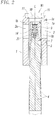
Fig. 2] Fig. 2 is a partially enlarged cross-sectional view taken along line II-II ofFig. 1 . - [
Fig. 3] Fig. 3 is an enlarged view of the main components ofFig. 2 . - [
Fig. 4] Fig. 4 is a cross-sectional view taken along line IV-IV ofFig. 3 . - [
Fig. 5] Fig. 5 is a cross-sectional view taken along line V-V ofFig. 3 . - [
Fig. 6] Fig. 6 is a plan view of the main components ofFig. 3 . - [
Fig. 7] Fig. 7 is an exploded cross-sectional view of the gate valve. - [
Fig. 8] Fig. 8 is a perspective view ofFig. 7 . - [
Fig. 9] Fig. 9 is a cross-sectional view of the main components illustrating a state in which the connecting screw is loosened, and the valve plate is displaced to a valve plate detaching position. - [
Fig. 10] Fig. 10 is a perspective view of the main components in a state in which the valve plate is detached from the valve rod. - [
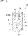
Fig. 11] Fig. 11 is a cross-sectional view of the main components of a gate valve of a second embodiment. -
Figs. 1 and10 illustrate a first embodiment of a gate valve according to the present invention. The gate valve V1 is attached to a vacuum chamber (not shown) for use and includes avalve casing 1 having anopening 2 that opens to a vacuum chamber, avalve plate 3 that opens and closes theopening 2 in thevalve casing 1, avalve rod 4 for opening and closing operations connected to thevalve plate 3, and avalve drive unit 5 that drives thevalve rod 4. Thevalve plate 3 is moved up and down between a raised position for closing the opening 2 (the solid line position inFig. 2 ) and a lowered position for opening the opening 2 (the chain line position inFig. 2 ) by driving thevalve rod 4 with thevalve drive unit 5. - The
valve drive unit 5 includes adriving mechanism 6 such as an air cylinder. Since the configurations and operations of thevalve drive unit 5 and thedriving mechanism 6 are well known, descriptions thereof will be omitted. - The
valve casing 1 has a laterally elongated rectangular box shape. Of the front andback side walls valve casing 1, thefront side wall 1a connected to the vacuum chamber includes the laterally elongatedrectangular opening 2. Aflat valve seat 1c enclosing theopening 2 is formed on the inner surface of theside wall 1a. Theopening 2 is closed by thevalve plate 3 moving to the raised position indicated by the solid line inFig. 2 and then changing in position to thefront side wall 1a to push thesealing member 7 against thevalve seat 1c. - A
cover 10 is detachably attached to the top of thevalve casing 1 with a plurality ofcover attaching screws 11. As shown inFigs. 7 and8 , the top of thevalve casing 1 can be opened by removing thecover 10, thevalve plate 3 can be detached from thevalve rod 4 along the rod axis L through awindow hole 12 at the top of the opened valve casing, and the detachedvalve plate 3 can be taken up from thevalve casing 1. - The
back side wall 1b of thevalve casing 1 also has an opening 2a. However, the opening 2a is not opened and closed by thevalve plate 3. - The
valve plate 3 has a laterally elongated rectangular shape in front view, as is apparent fromFig. 8 . The opposite ends of thevalve plate 3 in the longitudinal direction are semicircular or nearly circular because the four corners of the rectangle are chamfered in an arc. As shown inFig. 7 , thevalve plate 3 includes avalve front surface 3a fitted with thesealing member 7, avalve back surface 3b opposite to thevalve front surface 3a, a valveupper surface 3c, and a valvelower surface 3d. Thevalve front surface 3a, thevalve back surface 3b, the valveupper surface 3c, and the valvelower surface 3d are substantially flat. - The
valve plate 3 is detachably connected to the upper end of thevalve rod 4 along the rod axis L with a connectingscrew 14. For the connection, a connectinghole 15 in which a connectingportion 16 at the upper end of thevalve rod 4 is fitted is formed upward along the rod axis L at the center of the valvelower surface 3d in the longitudinal direction. The depth of the connectinghole 15 is merely a little larger than half of the height (vertical width) H of thevalve plate 3, so that the connectinghole 15 does not pass through thevalve plate 3 in the direction of the height H. - The connecting
hole 15 has a rectangular shape that is long in the longitudinal direction of thevalve plate 3 in cross section, as apparent fromFigs. 4 and5 . Afirst hole surface 15a and asecond hole surface 15b on one side and the other side of the connectinghole 15 in the widthwise direction are flat surfaces parallel to each other. Athird hole surface 15c and afourth hole surface 15d on one side and the other side of the connectinghole 15 in the longitudinal direction are also flat surfaces parallel to each other. - As shown in detail in
Figs. 3 and8 , the valveupper surface 3c of thevalve plate 3 has ascrew insertion hole 18 through which the connectingscrew 14 passes and screw-rod attaching holes 20 in which screw rods 19 (seeFig. 10 ) for lifting thevalve plate 3 by hand are to be attached. - The
screw insertion hole 18 is formed at the center of thevalve plate 3 in the longitudinal direction along the rod axis L so as to reach the connectinghole 15. Thescrew insertion hole 18 has acircular counterbore 18a in which ascrew head 14a of the connectingscrew 14 is housed and acircular insertion portion 18b in which ascrew shaft 14b of the connectingscrew 14 is inserted. Thecounterbore 18a is larger in diameter than theinsertion portion 18b. - The screw-
rod attaching holes 20 are formed at two positions that are symmetric about thescrew insertion hole 18 and have a depth so as not to pass through thevalve plate 3 in the height H direction. - The connecting
portion 16 of thevalve rod 4 is formed at the upper end of thecolumnar valve rod 4. The cross-sectional shape of the connectingportion 16 is a rectangle that is long in the longitudinal direction of thevalve plate 3, as apparent fromFigs. 3 to 5 . Of afirst side surface 16a and asecond side surface 16b on one side and the other side of the connectingportion 16 in the widthwise direction, thefirst side surface 16a on one side is entirely flat, while thesecond side surface 16b on the other side includes a flat portion 16b1 parallel to thefirst side surface 16a and a protrusion 16b2 partly formed only at part of the lower end of the flat portion 16b1. Since the protrusion 16b2 protrudes outward from the flat portion 16b1, the thickness of the connecting portion 16 (the dimension in the widthwise direction) is larger at the portion of the protrusion 16b2 than that at the flat portion 16b1. - A
third side surface 16c and afourth side surface 16d on one end and the other end of the connectingportion 16 in the longitudinal direction are arcuate. - Inserting the connecting
portion 16 of thevalve rod 4 into the connectinghole 15 of thevalve plate 3 and fixing thevalve plate 3 to thevalve rod 4 with the connectingscrew 14 causes the protrusion 16b2 of thesecond side surface 16b of the connectingportion 16 to fit in the connectinghole 15 into contact with the lower end of thesecond hole surface 15b to thereby strongly push thefirst side surface 16a of the connectingportion 16 against thefirst hole surface 15a of the connectinghole 15, causing the connectingportion 16 to be firmly pressure-fitted in the connectinghole 15, as shown inFig. 3 . - However, when the protrusion 16b2 of the
second side surface 16b comes off the connectinghole 15 downward to come out of contact with thesecond hole surface 15b, as shown inFig. 9 , only the flat portion 16b1 is kept fitted in the connectinghole 15. This loosens the fitting of the connectingportion 16 to the connectinghole 15, making it easy to detach thevalve plate 3 from thevalve rod 4. - A
recess 17 is provided at the upper end of the connectingportion 16 so as to cross the longitudinal center of the connectingportion 16 in the widthwise direction of the connectingportion 16. Ascrew hole 21 for screwing the connectingscrew 14 is provided at the bottom of therecess 17 along the rod axis L.An air vent 22 for letting out the air in thescrew hole 21 when the connectingscrew 14 is screwed is provided near the lower end of thescrew hole 21. Theair vent 22 is open to the flat portion 16b1 of thesecond side surface 16b of the connectingportion 16. - The connecting
screw 14 includes ascrew shaft 14b having a helical groove (external thread) 14c at the end and thecircular screw head 14a larger in diameter than thescrew shaft 14b. At the top of thescrew head 14a, ahexagonal operation hole 14d with which a tool 28 (seeFig. 9 ) such as a hexagonal wrench is to be engaged for a rotating operation is provided. By inserting the connectingscrew 14 into thescrew insertion hole 18 of thevalve plate 3 and screwing theexternal thread 14c at the end of thescrew shaft 14b into thescrew hole 21 at the upper end of thevalve rod 4, thevalve plate 3 is connected to the upper end of thevalve rod 4. At that time, the lower surface of thescrew head 14a of the connectingscrew 14 is in contact with the upper surface of abottom wall 18c of thecounterbore 18a via awasher 23. - The
counterbore 18a of thescrew insertion hole 18 formed in thevalve plate 3 is provided with acontact portion 25 that comes into contact with thescrew head 14a of the connectingscrew 14 when the connectingscrew 14 is loosened to detach thevalve plate 3 from thevalve rod 4. Thecontact portion 25 is formed of a ring-shapedmember 25a, which is a C-ring in the illustrated example. Thecounterbore 18a has an attachinggroove 26 around the inner periphery to attach the ring-shaped member, that is, the C-ring 25a. The C-ring 25a is attached to the attachinggroove 26, and the upper outer periphery of thescrew head 14a is in contact with the C-ring 25a via a ring-shapedwasher 27. Since the C-ring 25a and thewasher 27 are ring-shaped, the operation of tightening or loosening the connectingscrew 14 with thetool 28 can be performed through the hollows of the C-ring 25a and thewasher 27. - In the gate valve V1 with the above configuration, when the
valve plate 3 is to be detached from thevalve rod 4 to perform maintenance, such as replacement of the sealingmember 7, thecover 10 at the top of thevalve casing 1 is detached to open thewindow hole 12. In this state, the connectingscrew 14 is detached from thescrew hole 21 at the upper end of thevalve rod 4 by engaging thetool 28 with theoperation hole 14d of thescrew head 14a of the connectingscrew 14, as shown inFig. 9 , and rotating the connectingscrew 14 to loosen it with thetool 28. This causes the outer periphery of the upper surface of thescrew head 14a to come into contact with thecontact portion 25 via thewasher 27 as the connectingscrew 14 moves in the loosening direction (upward inFig. 9 ) along the rod axis L, and the impellent force of the connectingscrew 14 to act upward on thevalve plate 3 via thecontact portion 25. This causes thevalve plate 3 to move in the direction of the rod axis L with respect to thevalve rod 4 together with the connectingscrew 14. - When the
valve plate 3 moves to a position at which theexternal thread 14c at the lower end of thescrew shaft 14b of the connectingscrew 14 comes out of thescrew hole 21 of thevalve rod 4 completely, the protrusion 16b2 at the lower end of thesecond side surface 16b of the connectingportion 16 of thevalve rod 4 comes out downward from the connectinghole 15 of thevalve plate 3. This brings the connectinghole 15 and the connectingportion 16, which have been tightly pressure-fitted, into a loosely fitted state, allowing thevalve plate 3 to be easily detached from thevalve rod 4. Thus, this position is a valve-plate detaching position at which thevalve plate 3 can be detached from thevalve rod 4 by lifting thevalve plate 3 by hand. - Accordingly, by attaching the
screw rods 19 in the two screw-rod attaching holes 20 formed in the upper surface of thevalve plate 3 and lifting thevalve plate 3 by holding thescrew rods 19 in both hands, thevalve plate 3 can be detached from thevalve rod 4 to the outside of thevalve casing 1, as shown inFig. 10 . - Since the
screw head 14a of the connectingscrew 14 is kept engaged with thebottom wall 18c and thecontact portion 25 in thecounterbore 18a after thevalve plate 3 is taken out of thevalve casing 1, the connectingscrew 14 does not come off thevalve plate 3. - The
valve plate 3 taken out from thevalve casing 1 receives necessary maintenance, such as replacement of the sealingmember 7, after thescrew rods 19 are detached as appropriate. - When the
valve plate 3 for which maintenance has been completed is to be attached thevalve rod 4 again, an operation reverse to the operation for detaching thevalve plate 3 is performed. - Specifically, as shown in
Fig. 10 , thescrew rods 19 are attached to thevalve plate 3, thevalve plate 3 is housed in thevalve casing 1 with thescrew rods 19 in hands, the connectingportion 16 of thevalve rod 4 is fitted in the connectinghole 15 of thevalve plate 3, and thevalve plate 3 is moved down to a position at which the end of thescrew shaft 14b of the connectingscrew 14 comes into contact with the inlet of thescrew hole 21 at the upper end of the connectingportion 16. - Next, after the
screw rods 19 are detached from thevalve plate 3, the connectingscrew 14 is rotated and screwed with thetool 28 into thescrew hole 21, as shown inFig. 9 , to a position at which anupper end face 16e of the connectingportion 16 comes into contact with a hole bottom 15e of the connectinghole 15, and the protrusion 16b2 at the lower end of thesecond side surface 16b of the connectingportion 16 is fitted in the connectinghole 15 into contact with thesecond hole surface 15b, so that thevalve plate 3 is attached to thevalve rod 4, as shown inFigs. 2 to 4 . - By attaching the
cover 10 to the top of thevalve casing 1 with thecover attaching screws 11, the mounting of thevalve plate 3 is completed. - In the above example, the operation of detaching the
valve plate 3 from thevalve rod 4 to take it out from thevalve casing 1 is performed by holding thescrew rods 19 attached to thevalve plate 3 in hands. Alternatively, if the valvefront surface 3a or the valve backsurface 3b of thevalve plate 3 has a recess or the like in which a finger is to be hooked, thevalve plate 3 can be detached from thevalve rod 4 to the outside of thevalve casing 1 using the recess. In this case, there is no need to attach thescrew rods 19 to thevalve plate 3, and therefore thescrew rods 19 and the screw-rod attaching holes 20 are not needed. -
Fig. 11 illustrates the main components of a gate valve V2 of a second embodiment. In the gate valve V2 of the second embodiment, thecontact portion 25 at thevalve plate 3 is made of a rod-like member 25b. Specifically, the rod-like member 25b is a contact screw. The rod-like member, or the contact screw 25b, is attached to the valve backsurface 3b of thevalve plate 3 so as to move back and force at a horizontal orientation, and an end of the contact screw 25b protrudes from the inner periphery of thecounterbore 18a to the interior of thecounterbore 18a. - The
screw head 14a of the connectingscrew 14 has a ring-shapedcontact groove 29 around the outer periphery of the side surface of thescrew head 14a. An end of the contact screw 25b is fitted in thecontact groove 29 so as to be freely displaced in the direction of rotation about the rod axis L relative to the connectingscrew 14 but is fixed in the direction of the rod axis L. - The other configuration and operation of the gate valve V2 of the second embodiment are substantially the same as the configuration and operation of the gate valve V1 of the first embodiment, and detailed descriptions thereof will be omitted.
- The illustrated example includes one contact screw 25b. Alternatively, the contact screw 25b may be provided at each of the valve
front surface 3a and the valve backsurface 3b of thevalve plate 3, that is, two at the opposite positions in the diametrical direction of thecounterbore 18a. - The ring-shaped
contact groove 29 may be a recessed-step-like groove formed around the rod axis L at a position near the outer periphery of the upper surface of thescrew head 14a. -
- V1, V2
- GATE VALVE
- 3
- VALVE PLATE
- 4
- VALVE ROD
- 14
- CONNECTING SCREW
- 14a
- SCREW HEAD
- 14b
- SCREW SHAFT
- 14c
- HELICAL GROOVE (EXTERNAL THREAD)
- 14d
- OPERATION HOLE
- 15
- CONNECTING HOLE
- 16
- CONNECTING PORTION
- 16b2
- PROTRUSION
- 18
- SCREW INSERTION HOLE
- 18a
- COUNTERBORE
- 18b
- INSERTION PORTION
- 21
- SCREW HOLE
- 25
- CONTACT PORTION
- 25a
- RING-SHAPED MEMBER (C-RING)
- 25b
- ROD-LIKE MEMBER (CONTACT SCREW)
- 27
- WASHER
Claims (7)
- A gate valve (V1, V2) in which a valve plate (3) and a valve rod (4) are detachably connected along a rod axis (L) by screwing a connecting screw (14) in a screw hole (21) formed at an end of a valve rod (4) along the rod axis (L) through a screw insertion hole (18) formed in a valve plate (3),
wherein the valve plate (3) includes a contact portion (25) that is in contact with the connecting screw (14), and when the connecting screw (14) is detached from the screw hole (21) to detach the valve plate (3) from the valve rod (4), the valve plate (3) is displaced along the rod axis (L) together with the connecting screw (14) by an impellent force of the connecting screw (14) acting on the valve plate (3) via the contact portion (25) to move to a valve-plate detaching position which is a position at which the connecting screw (14) comes out of the screw hole (21) of the valve rod (4) completely. - The gate valve according to Claim 1,
wherein the connecting screw (14) includes a screw shaft (14b) in which a helical groove (14c) is formed around an outer periphery and a screw head (14a) larger in diameter than the screw shaft (14b), wherein the screw head (14a) has an operation hole (14d) with which a tool (28) for a rotating operation is to be engaged, and
wherein the screw insertion hole (18) includes a counterbore (18a) in which the screw head (14a) of the connecting screw (14) is fitted and an insertion portion (18b) through which the screw shaft (14b) of the connecting screw (14) passes, wherein, in the counterbore (18a), the contact portion (25) is formed so as to be in contact with the screw head (14a) of the connecting screw (14). - The gate valve according to Claim 2, wherein the contact portion (25) includes a ring-shaped member (25a) attached to an inner periphery of the counterbore (18a), wherein the ring-shaped contact portion (25) is in contact with an upper surface of the screw head (14a) of the connecting screw (14).
- The gate valve according to Claim 3, wherein a washer (27) is interposed between the screw head (14a) and the contact portion (25).
- The gate valve according to Claim 2, wherein the contact portion (25) includes a rod-like member (25b) attached to the valve plate (3) in such a manner that an end protrudes to an interior of the counterbore (18a), and the screw head (14a) of the connecting screw (14) includes a contact groove (29) in which the rod-like contact portion (25) is fitted.
- The gate valve according to any of Claims 1 to 5, wherein the connecting screw (14) is prevented from coming off the valve plate (3) by being in contact with the contact portion (25) also after the valve plate (3) is detached from the valve rod (4).
- The gate valve according to any of Claims 1 to 6, wherein, when the valve plate (3) is connected to the valve rod (4) with the connecting screw (14), a connecting hole (15) of the valve plate (3) and a connecting portion (16) of the valve rod (4) are tightly fitted in each other by a protrusion (16b2) formed at part of the connecting portion (16) being fitted in the connecting hole (15), and when the valve plate (3) moves to the valve-plate detaching position, the connecting hole (15) and the connecting portion (16) are loosely fitted because the protrusion (16b2) of the connecting portion (16) comes out of the connecting hole (15).
Applications Claiming Priority (1)
| Application Number | Priority Date | Filing Date | Title |
|---|---|---|---|
| JP2020103857A JP7479586B2 (en) | 2020-06-16 | 2020-06-16 | Gate valve |
Publications (1)
| Publication Number | Publication Date |
|---|---|
| EP3936744A1 true EP3936744A1 (en) | 2022-01-12 |
Family
ID=76325410
Family Applications (1)
| Application Number | Title | Priority Date | Filing Date |
|---|---|---|---|
| EP21178158.8A Pending EP3936744A1 (en) | 2020-06-16 | 2021-06-08 | Gate valve |
Country Status (6)
| Country | Link |
|---|---|
| US (1) | US11402024B2 (en) |
| EP (1) | EP3936744A1 (en) |
| JP (1) | JP7479586B2 (en) |
| KR (1) | KR102951130B1 (en) |
| CN (1) | CN113803484A (en) |
| TW (1) | TWI879978B (en) |
Families Citing this family (2)
| Publication number | Priority date | Publication date | Assignee | Title |
|---|---|---|---|---|
| JP7783728B2 (en) * | 2021-12-02 | 2025-12-10 | 株式会社モリタ製作所 | Data processing device, data processing method, data processing program, and data processing system |
| CN118979994A (en) * | 2024-09-30 | 2024-11-19 | 东方电气集团东方电机有限公司 | A valve shaft connecting pin and use method thereof |
Citations (4)
| Publication number | Priority date | Publication date | Assignee | Title |
|---|---|---|---|---|
| US6082706A (en) * | 1996-05-07 | 2000-07-04 | Irie Koken Co., Ltd. | Non-sliding vacuum gate valve |
| JP2005291221A (en) | 2004-03-31 | 2005-10-20 | Vat Holding Ag | Vacuum gate valve, valve plate, and multi-functional tool |
| EP3511600A1 (en) * | 2018-01-10 | 2019-07-17 | SMC Corporation | Mounting structure of valve plate with respect to valve rod |
| EP3754239A1 (en) * | 2019-06-19 | 2020-12-23 | SMC Corporation | Mounting structure for mounting valve plate to valve rod in gate valve, and gate valve having mounting structure |
Family Cites Families (9)
| Publication number | Priority date | Publication date | Assignee | Title |
|---|---|---|---|---|
| JP2636063B2 (en) * | 1990-04-27 | 1997-07-30 | キヤノン株式会社 | Fine adjustment mechanism for position detection means of industrial robot |
| ES1014724Y (en) * | 1990-07-09 | 1991-10-16 | Orona S. Coop. Ltda. | PERFECTED DEVICE FOR THE FORMATION OF SPECIAL STRUCTURES. |
| US6736368B2 (en) * | 2002-07-22 | 2004-05-18 | Eagle Industry Co., Ltd. | Gate valve |
| US7100892B2 (en) * | 2003-08-26 | 2006-09-05 | Kitz Sct Corporation | Non-rubbing gate valve for semiconductor fabrication apparatus |
| CN2663712Y (en) * | 2003-11-26 | 2004-12-15 | 姚震华 | Pipe jointer |
| KR100960030B1 (en) * | 2004-03-12 | 2010-05-28 | 배트 홀딩 아게 | Vacuum gate valve |
| CN101767442A (en) * | 2009-12-30 | 2010-07-07 | 江苏新美星包装机械有限公司 | Regulating device of strip lamp in heating furnace |
| JP5811320B2 (en) | 2011-04-21 | 2015-11-11 | Smc株式会社 | Gate valve |
| CN207364333U (en) * | 2017-10-30 | 2018-05-15 | 圣邦集团有限公司 | A kind of restriction adjustable type three-way flowrate valve |
-
2020
- 2020-06-16 JP JP2020103857A patent/JP7479586B2/en active Active
-
2021
- 2021-06-08 EP EP21178158.8A patent/EP3936744A1/en active Pending
- 2021-06-08 US US17/341,523 patent/US11402024B2/en active Active
- 2021-06-09 TW TW110120900A patent/TWI879978B/en active
- 2021-06-14 KR KR1020210076519A patent/KR102951130B1/en active Active
- 2021-06-16 CN CN202110663557.3A patent/CN113803484A/en active Pending
Patent Citations (4)
| Publication number | Priority date | Publication date | Assignee | Title |
|---|---|---|---|---|
| US6082706A (en) * | 1996-05-07 | 2000-07-04 | Irie Koken Co., Ltd. | Non-sliding vacuum gate valve |
| JP2005291221A (en) | 2004-03-31 | 2005-10-20 | Vat Holding Ag | Vacuum gate valve, valve plate, and multi-functional tool |
| EP3511600A1 (en) * | 2018-01-10 | 2019-07-17 | SMC Corporation | Mounting structure of valve plate with respect to valve rod |
| EP3754239A1 (en) * | 2019-06-19 | 2020-12-23 | SMC Corporation | Mounting structure for mounting valve plate to valve rod in gate valve, and gate valve having mounting structure |
Also Published As
| Publication number | Publication date |
|---|---|
| US20210388907A1 (en) | 2021-12-16 |
| JP7479586B2 (en) | 2024-05-09 |
| KR20210155768A (en) | 2021-12-23 |
| CN113803484A (en) | 2021-12-17 |
| JP2021196015A (en) | 2021-12-27 |
| TW202204790A (en) | 2022-02-01 |
| KR102951130B1 (en) | 2026-04-10 |
| US11402024B2 (en) | 2022-08-02 |
| TWI879978B (en) | 2025-04-11 |
Similar Documents
| Publication | Publication Date | Title |
|---|---|---|
| US10876639B2 (en) | Mounting structure of valve plate with respect to valve rod | |
| US11402024B2 (en) | Gate valve | |
| JP7385185B2 (en) | Mounting structure of a valve plate to a valve rod in a gate valve, and a gate valve having the mounting structure | |
| US10253889B2 (en) | Gate valve | |
| JP2019120380A5 (en) | ||
| TWI738274B (en) | Internal gear retention mechanism | |
| US7455474B2 (en) | Device permitting a plug or a cover to lock in a detachable manner onto a frame | |
| EP4239150A1 (en) | Driving device | |
| US20050251963A1 (en) | Hinge for furniture | |
| KR200382037Y1 (en) | Opening and shutting display device of valve | |
| JP3604086B2 (en) | Valve structure | |
| ES2998115T3 (en) | Closure holder for a door closure | |
| JP5143756B2 (en) | Fluid controller | |
| KR200364630Y1 (en) | Structure of hinge for shrine | |
| JP4842600B2 (en) | High performance air filter built-in outlet filter unit | |
| JP4451351B2 (en) | Housing for lighting equipment | |
| CN119531678A (en) | A padlock replacement lock core and lock | |
| KR200452332Y1 (en) | Installation change structure of the walk-in cooler door | |
| EP1367263A2 (en) | Support for fitting sensors on pneumatic or hydraulic cylinders | |
| KR20090003222U (en) | Adjuster assembly of financial automation equipment | |
| JP2001047373A (en) | Monkey wrench | |
| JPH09158641A (en) | Gate lock device | |
| JP2010242771A (en) | Position detection switch mounting mechanism in fluid pressure equipment |
Legal Events
| Date | Code | Title | Description |
|---|---|---|---|
| PUAI | Public reference made under article 153(3) epc to a published international application that has entered the european phase |
Free format text: ORIGINAL CODE: 0009012 |
|
| STAA | Information on the status of an ep patent application or granted ep patent |
Free format text: STATUS: THE APPLICATION HAS BEEN PUBLISHED |
|
| AK | Designated contracting states |
Kind code of ref document: A1 Designated state(s): AL AT BE BG CH CY CZ DE DK EE ES FI FR GB GR HR HU IE IS IT LI LT LU LV MC MK MT NL NO PL PT RO RS SE SI SK SM TR |
|
| B565 | Issuance of search results under rule 164(2) epc |
Effective date: 20211209 |
|
| STAA | Information on the status of an ep patent application or granted ep patent |
Free format text: STATUS: REQUEST FOR EXAMINATION WAS MADE |
|
| 17P | Request for examination filed |
Effective date: 20220711 |
|
| RBV | Designated contracting states (corrected) |
Designated state(s): AL AT BE BG CH CY CZ DE DK EE ES FI FR GB GR HR HU IE IS IT LI LT LU LV MC MK MT NL NO PL PT RO RS SE SI SK SM TR |
|
| STAA | Information on the status of an ep patent application or granted ep patent |
Free format text: STATUS: EXAMINATION IS IN PROGRESS |
|
| 17Q | First examination report despatched |
Effective date: 20230915 |
|
| RAP3 | Party data changed (applicant data changed or rights of an application transferred) |
Owner name: SMC CORPORATION |
|
| GRAP | Despatch of communication of intention to grant a patent |
Free format text: ORIGINAL CODE: EPIDOSNIGR1 |
|
| STAA | Information on the status of an ep patent application or granted ep patent |
Free format text: STATUS: GRANT OF PATENT IS INTENDED |
|
| INTG | Intention to grant announced |
Effective date: 20260407 |