EP3936743A1 - Cylinder boot for axle of industrial vehicle - Google Patents
Cylinder boot for axle of industrial vehicle Download PDFInfo
- Publication number
- EP3936743A1 EP3936743A1 EP21179552.1A EP21179552A EP3936743A1 EP 3936743 A1 EP3936743 A1 EP 3936743A1 EP 21179552 A EP21179552 A EP 21179552A EP 3936743 A1 EP3936743 A1 EP 3936743A1
- Authority
- EP
- European Patent Office
- Prior art keywords
- cylinder
- boot
- rod
- axle
- detection
- Prior art date
- Legal status (The legal status is an assumption and is not a legal conclusion. Google has not performed a legal analysis and makes no representation as to the accuracy of the status listed.)
- Granted
Links
- 238000001514 detection method Methods 0.000 claims abstract description 76
- 230000004044 response Effects 0.000 claims abstract description 7
- 239000002184 metal Substances 0.000 claims description 3
- 239000011248 coating agent Substances 0.000 claims description 2
- 238000000576 coating method Methods 0.000 claims description 2
- 230000008602 contraction Effects 0.000 description 9
- 230000002093 peripheral effect Effects 0.000 description 6
- 239000000463 material Substances 0.000 description 3
- 230000003287 optical effect Effects 0.000 description 3
- 239000004575 stone Substances 0.000 description 3
- 238000013459 approach Methods 0.000 description 2
- 230000008878 coupling Effects 0.000 description 2
- 238000010168 coupling process Methods 0.000 description 2
- 238000005859 coupling reaction Methods 0.000 description 2
- 238000006073 displacement reaction Methods 0.000 description 2
- 238000012986 modification Methods 0.000 description 2
- 230000004048 modification Effects 0.000 description 2
- 230000009467 reduction Effects 0.000 description 2
- 230000005540 biological transmission Effects 0.000 description 1
- 239000000428 dust Substances 0.000 description 1
- 230000000694 effects Effects 0.000 description 1
- 239000010720 hydraulic oil Substances 0.000 description 1
- 230000001939 inductive effect Effects 0.000 description 1
- 238000009434 installation Methods 0.000 description 1
- 230000007246 mechanism Effects 0.000 description 1
- 238000000034 method Methods 0.000 description 1
- XLYOFNOQVPJJNP-UHFFFAOYSA-N water Substances O XLYOFNOQVPJJNP-UHFFFAOYSA-N 0.000 description 1
- 239000013585 weight reducing agent Substances 0.000 description 1
- 238000003466 welding Methods 0.000 description 1
Images


Classifications
-
- F—MECHANICAL ENGINEERING; LIGHTING; HEATING; WEAPONS; BLASTING
- F15—FLUID-PRESSURE ACTUATORS; HYDRAULICS OR PNEUMATICS IN GENERAL
- F15B—SYSTEMS ACTING BY MEANS OF FLUIDS IN GENERAL; FLUID-PRESSURE ACTUATORS, e.g. SERVOMOTORS; DETAILS OF FLUID-PRESSURE SYSTEMS, NOT OTHERWISE PROVIDED FOR
- F15B15/00—Fluid-actuated devices for displacing a member from one position to another; Gearing associated therewith
- F15B15/08—Characterised by the construction of the motor unit
- F15B15/14—Characterised by the construction of the motor unit of the straight-cylinder type
- F15B15/1423—Component parts; Constructional details
- F15B15/1457—Piston rods
- F15B15/1461—Piston rod sealings
-
- B—PERFORMING OPERATIONS; TRANSPORTING
- B60—VEHICLES IN GENERAL
- B60B—VEHICLE WHEELS; CASTORS; AXLES FOR WHEELS OR CASTORS; INCREASING WHEEL ADHESION
- B60B35/00—Axle units; Parts thereof ; Arrangements for lubrication of axles
- B60B35/003—Steerable axles
-
- B—PERFORMING OPERATIONS; TRANSPORTING
- B62—LAND VEHICLES FOR TRAVELLING OTHERWISE THAN ON RAILS
- B62D—MOTOR VEHICLES; TRAILERS
- B62D15/00—Steering not otherwise provided for
- B62D15/02—Steering position indicators ; Steering position determination; Steering aids
- B62D15/021—Determination of steering angle
- B62D15/0225—Determination of steering angle by measuring on a steering gear element, e.g. on a rack bar
-
- B—PERFORMING OPERATIONS; TRANSPORTING
- B62—LAND VEHICLES FOR TRAVELLING OTHERWISE THAN ON RAILS
- B62D—MOTOR VEHICLES; TRAILERS
- B62D5/00—Power-assisted or power-driven steering
- B62D5/06—Power-assisted or power-driven steering fluid, i.e. using a pressurised fluid for most or all the force required for steering a vehicle
- B62D5/062—Details, component parts
-
- B—PERFORMING OPERATIONS; TRANSPORTING
- B62—LAND VEHICLES FOR TRAVELLING OTHERWISE THAN ON RAILS
- B62D—MOTOR VEHICLES; TRAILERS
- B62D5/00—Power-assisted or power-driven steering
- B62D5/06—Power-assisted or power-driven steering fluid, i.e. using a pressurised fluid for most or all the force required for steering a vehicle
- B62D5/10—Power-assisted or power-driven steering fluid, i.e. using a pressurised fluid for most or all the force required for steering a vehicle characterised by type of power unit
- B62D5/12—Piston and cylinder
-
- B—PERFORMING OPERATIONS; TRANSPORTING
- B62—LAND VEHICLES FOR TRAVELLING OTHERWISE THAN ON RAILS
- B62D—MOTOR VEHICLES; TRAILERS
- B62D7/00—Steering linkage; Stub axles or their mountings
- B62D7/18—Steering knuckles; King pins
-
- B—PERFORMING OPERATIONS; TRANSPORTING
- B66—HOISTING; LIFTING; HAULING
- B66F—HOISTING, LIFTING, HAULING OR PUSHING, NOT OTHERWISE PROVIDED FOR, e.g. DEVICES WHICH APPLY A LIFTING OR PUSHING FORCE DIRECTLY TO THE SURFACE OF A LOAD
- B66F9/00—Devices for lifting or lowering bulky or heavy goods for loading or unloading purposes
- B66F9/06—Devices for lifting or lowering bulky or heavy goods for loading or unloading purposes movable, with their loads, on wheels or the like, e.g. fork-lift trucks
- B66F9/075—Constructional features or details
- B66F9/07568—Steering arrangements
-
- F—MECHANICAL ENGINEERING; LIGHTING; HEATING; WEAPONS; BLASTING
- F16—ENGINEERING ELEMENTS AND UNITS; GENERAL MEASURES FOR PRODUCING AND MAINTAINING EFFECTIVE FUNCTIONING OF MACHINES OR INSTALLATIONS; THERMAL INSULATION IN GENERAL
- F16J—PISTONS; CYLINDERS; SEALINGS
- F16J15/00—Sealings
- F16J15/50—Sealings between relatively-movable members, by means of a sealing without relatively-moving surfaces, e.g. fluid-tight sealings for transmitting motion through a wall
- F16J15/52—Sealings between relatively-movable members, by means of a sealing without relatively-moving surfaces, e.g. fluid-tight sealings for transmitting motion through a wall by means of sealing bellows or diaphragms
-
- F—MECHANICAL ENGINEERING; LIGHTING; HEATING; WEAPONS; BLASTING
- F16—ENGINEERING ELEMENTS AND UNITS; GENERAL MEASURES FOR PRODUCING AND MAINTAINING EFFECTIVE FUNCTIONING OF MACHINES OR INSTALLATIONS; THERMAL INSULATION IN GENERAL
- F16J—PISTONS; CYLINDERS; SEALINGS
- F16J15/00—Sealings
- F16J15/56—Other sealings for reciprocating rods
-
- F—MECHANICAL ENGINEERING; LIGHTING; HEATING; WEAPONS; BLASTING
- F16—ENGINEERING ELEMENTS AND UNITS; GENERAL MEASURES FOR PRODUCING AND MAINTAINING EFFECTIVE FUNCTIONING OF MACHINES OR INSTALLATIONS; THERMAL INSULATION IN GENERAL
- F16J—PISTONS; CYLINDERS; SEALINGS
- F16J3/00—Diaphragms; Bellows; Bellows pistons
- F16J3/04—Bellows
- F16J3/041—Non-metallic bellows
-
- G—PHYSICS
- G01—MEASURING; TESTING
- G01B—MEASURING LENGTH, THICKNESS OR SIMILAR LINEAR DIMENSIONS; MEASURING ANGLES; MEASURING AREAS; MEASURING IRREGULARITIES OF SURFACES OR CONTOURS
- G01B11/00—Measuring arrangements characterised by the use of optical techniques
- G01B11/26—Measuring arrangements characterised by the use of optical techniques for measuring angles or tapers; for testing the alignment of axes
-
- B—PERFORMING OPERATIONS; TRANSPORTING
- B60—VEHICLES IN GENERAL
- B60B—VEHICLE WHEELS; CASTORS; AXLES FOR WHEELS OR CASTORS; INCREASING WHEEL ADHESION
- B60B2900/00—Purpose of invention
- B60B2900/20—Avoidance of
- B60B2900/212—Damage
-
- B—PERFORMING OPERATIONS; TRANSPORTING
- B62—LAND VEHICLES FOR TRAVELLING OTHERWISE THAN ON RAILS
- B62D—MOTOR VEHICLES; TRAILERS
- B62D7/00—Steering linkage; Stub axles or their mountings
- B62D7/16—Arrangement of linkage connections
Definitions
- the present disclosure relates to a cylinder boot for an axle of an industrial vehicle.
- a cylinder cover for an industrial vehicle disclosed in Japanese Patent Application Publication No. 2006-160151 is known as a conventional art related to a cylinder boot for an axle of an industrial vehicle, for example.
- the cylinder cover for an industrial vehicle disclosed in Japanese Patent Application Publication No. 2006-160151 protects, in a forklift, a cylinder rod of a steering cylinder mounted between a rod coupling-side knuckle arm of a steering knuckle, which makes relative displacement, and a rear beam axle of a vehicle body of the forklift.
- This cover includes a cover member that is stretchable and deformable in response to the extension or contraction of the cylinder rod of the steering cylinder.
- the cover member has a sheet shape and is disposed between the rod coupling-side knuckle arm of the steering knuckle, which makes relative displacement, and the rear beam axle of the vehicle body to protect the cylinder rod of the steering cylinder from harmful objects, such as stones and/or mud.
- the cover member has a sheet shape and is elastic so that the cover member is stretchable and deformable in a direction in which the steering cylinder extends or contracts. This configuration allows the cover member to be compactly disposed in a sheet shape to block harmful objects that may fly toward the cylinder rod of the steering cylinder, thereby reducing the installation space for the cover.
- Japanese Registered Utility Model No. 3144024 discloses, as another conventional art, a, mounting structure for mounting a cylinder boot on a movable-side member, wherein the cylinder boot covers a cylinder rod and the like of a cylinder of an industrial vehicle to protect the cylinder rod and the like from rain water, dust, and the like.
- the cylinder cover for an industrial vehicle disclosed in Japanese Patent Application Publication No. 2006-160151 is not a member that covers the cylinder rod, and therefore may be inferior to the cylinder boot disclosed in Japanese Registered Utility Model No. 3144024 , which covers the cylinder rod and the like, in terms of protection of the cylinder rod from foreign matters.
- An industrial vehicle may detect whether the steering angle of a steered wheel has exceeded a threshold value.
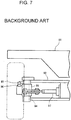
- an beam axle 92 of a vehicle body 91 may be provided with a detection sensor 93, and a detection object 96 disposed on a steering knuckle 95 that is pivotable via a king pin 94.
- the steering knuckle 95 pivots so that the detection sensor 93 detects the detection object 96 and transmits a detection signal. This enables detection of whether or not the steering angle of the steered wheel has exceeded the threshold value.
- this configuration requires processing of the steering knuckle 95 for mounting the detection object 96 to the steering knuckle 95 or addition of a member, such as a bracket, for mounting the detection object 96.
- the detection sensor 93 and the detection object 96 are provided at positions where they easily get dirty and are likely to interfere with foreign matters, such as a stone flying from the road surface.
- the mounting structure of the cylinder boot of Japanese Registered Utility Model No. 3144024 is merely a technique for facilitating the assembly of the cylinder boot.
- the present disclosure which has been made in light of the above-mentioned problem, is directed to providing a cylinder boot for an axle of an industrial vehicle, wherein the cylinder boot protects a cylinder rod and serves as a detection object used for detection of a steering angle.
- a cylinder boot for an axle of an industrial vehicle.
- the industrial vehicle has a beam axle, a steering knuckle pivotably supported by the beam axle and a steering hydraulic cylinder supported by the beam axle.
- a cylinder rod of the steering hydraulic cylinder is connected to the steering knuckle to pivot the steering knuckle.
- the cylinder boot covers the cylinder rod of the steering hydraulic cylinder.
- the cylinder boot includes a cylinder boot body, a rod-side fixing portion, a cylinder-side fixing portion, and a detection portion.
- the cylinder boot body has a contractable portion that is contractable in response to a stroke of the cylinder rod.
- the rod-side fixing portion is fixed to a distal end portion of the cylinder rod.
- the cylinder-side fixing portion is fixed to a cylinder body of the steering hydraulic cylinder.
- the detection portion is displaced in a direction in which the cylinder rod extends or contracts, and is detected by a detection sensor disposed on the beam axle.
- a cylinder boot for an axle of an industrial vehicle will be described below with reference to the drawings.
- the present embodiment is an example of application to a tow tractor, which corresponds to the industrial vehicle of the present disclosure.
- the "front and rear”, “right and left”, and “up and down” described herein for specifying the direction are defined based on a state where the operator of the tow tractor is seated on a driver's seat of the driver's section and faces the forward side of the tow tractor.
- a driver's section 12 is provided near the center of a vehicle body 11 of a tow tractor 10 that serves as a towing vehicle (i.e., the industrial vehicle of the present disclosure), and a battery 13 is accommodated in front of the driver's section 12 in the vehicle body 11.
- Steered wheels 14 as front wheels are provided in a front portion of the vehicle body 11, and driving wheels 15 as rear wheels are provided in a rear portion of the vehicle body 11.
- the vehicle body 11 is provided with a driving motor 16 as a driving device that generates driving force for driving the vehicle.
- a power transmission mechanism (not illustrated) that transmits the driving force of the driving motor 16 to the driving wheels 15 is provided between the driving motor 16 and the driving wheels 15.
- the tow tractor 10 of the present embodiment is a battery-type tow tractor that travels on the electric power of the battery 13 mounted on the vehicle body 11.
- the driver's section 12 in the vehicle body 11 is provided with driver's seats 17 arranged on the right and left.
- FIG. 1 illustrates only one of the driver's seats 17.
- a steering column 18 is provided in front of the driver's seat 17.
- a steering wheel 19 for changing the steering angle of the steered wheels 14 is mounted on the steering column 18.
- An accelerator pedal 21 is provided on a floor surface in front of the driver's seat 17.
- the tow tractor 10 controls driving of the driving motor 16 to adjust the vehicle speed in response to the pressing amount of the accelerator pedal 21 that is pressed down by the operator.
- a controller 22 that performs various controls of the tow tractor 10 is mounted below the driver's seat 17 in the vehicle body 11.
- a drawbar operating lever 25 is provided behind the driver's seat 17. The drawbar operating lever 25 is operated by the operator to cause the towed vehicle to be coupled to or decoupled from the drawbar device 24.
- the drawbar operating lever 25 is provided within the reach of the operator's hand in a state that the operator is seated on the driver's seat 17.
- the vehicle body 11 includes a front axle 26 in the front portion of the vehicle body 11, and the front axle 26 includes the steered wheels 14.
- the front axle 26 includes a front beam axle 27 that corresponds to the beam axle of the present disclosure and includes a base plate 31 extending in the right-left direction.
- the base plate 31 has an upper plate 32 and a lower plate 33 respectively on the upper portion and the lower portion of the base plate 31.
- the upper plate 32 and the lower plate 33 are fixed to the base plate 31 by welding, and a surface of the upper plate 32 and a surface of the lower plate 33 are parallel to each other.
- the base plate 31 has, in the front portion thereof, a connection plate 34 that connects the upper plate 32 and the lower plate 33.
- the longitudinal direction of the front beam axle 27 coincides with the width direction of the base plate 31, and a center pin 35 is inserted into the width center of the base plate 31.
- the front beam axle 27 is coupled to the vehicle body 11 by the center pin 35.
- the front beam axle 27 is provided with a pair of steering knuckles 36 that are respectively disposed at the right end and a left end of the front beam axle 27.
- Each of the steering knuckles 36 is supported by an upper boss portion 37 and a lower boss portion 38 into which a king pin 39 inserted so that the steering knuckle 36 is pivotable to the right and left via the king pin 39. That is, the steering knuckles 36 is pivotably supported by the front beam axle 27.
- the shapes of the pair of steering knuckles 36 are symmetrical to each other.
- the steering knuckle 36 has the king pin 39 extending in the up-down direction, a wheel spindle 40 protruding outward from the king pin 39 in the right-left direction of the vehicle body 11, and a knuckle arm 41 protruding frontward.
- An upper end portion of the king pin 39 protrudes upward from the steering knuckle 36, and a lower end portion of the king pin 39 protrudes downward from the steering knuckle 36.
- the wheel spindle 40 of the steering knuckle 36 supports the associated steered wheel 14 pivotally via a hub 42.
- the knuckle arm 41 has a distal end to which one ends of a pair of upper and lower tie rods 44 are pivotally coupled via a coupling pin 43.
- the tie rods 44 couple a steering hydraulic cylinder 45, which will be described below, and the steering knuckle 36. That is, the steering knuckle 36 is connected to and pivoted by the steering hydraulic cylinder 45.
- the steering hydraulic cylinder 45 (hereinafter simply referred to as "the hydraulic cylinder 45") is mounted to the front beam axle 27.
- the hydraulic cylinder 45 is a double-acting hydraulic cylinder that operates upon receiving supply of hydraulic oil in a hydraulic circuit (not illustrated).
- the hydraulic cylinder 45 includes a cylinder body 46 that is fixed to the base plate 31 by a bolt or the like (not illustrated).
- the inside of the cylinder body 46 is partitioned into two chambers by a piston (not illustrated).
- the piston is coupled to right and left cylinder rods 47 that respectively extend from the piston to the right and the left and protrude from the cylinder body 46.
- the cylinder rods 47 extend and contract in the right-left direction by the operation of the hydraulic cylinder 45.
- Each of the cylinder rod 47 has a distal end portion 48 that is pivotally coupled to the other ends of the tie rods 44 via a coupling pin 49 (see FIG. 3 ).
- Each cylinder rod 47 has a cylinder boot 50 for a front axle (hereinafter simply referred to as "the cylinder boot 50").
- the cylinder boot 50 is mounted to the cylinder rod 47 to protect the cylinder rod 47.
- the cylinder boot 50 includes a cylinder boot body 51, a rod-side fixing portion 52, a cylinder-side fixing portion 53, and a flange portion 54.
- the cylinder boot body 51 is made of a rubber material and has flexibility.
- the cylinder boot body 51 has a cylindrical portion 55 covering the cylinder rod 47, and a bellows-shaped cylindrical portion 56 extending in an axial direction of the cylinder rod 47 (an axial center P direction) from an end portion of the cylindrical portion 55.
- the bellows-shaped cylindrical portion 56 serves as a contractable portion of the cylinder boot body 51, and is configured to absorb an extension stroke and a contraction stroke of the cylinder rod 47.
- the cylindrical portion 55 is positioned adjacent to the distal end portion 48
- the bellows-shaped cylindrical portion 56 is positioned adjacent to the cylinder body 46.
- the rod-side fixing portion 52 is disposed at one end portion of the cylinder boot body 51.
- the rod-side fixing portion 52 includes a ring member 57 fixed to an inner peripheral surface of the one end portion of the cylinder boot body 51.
- the distal end portion 48 of the cylinder rod 47 is fixed to the rod-side fixing portion 52 by press-fitting (see FIG. 3 ).
- the cylinder-side fixing portion 53 is disposed at one end portion of the bellows-shaped cylindrical portion 56, which serves as the other end portion of the cylinder boot body 51.
- the cylinder-side fixing portion 53 includes a locking member 58 that is capable of being fixed to an end portion of the cylinder body 46 adjacent to the cylinder rod 47.
- the locking member 58 is not illustrated in FIG. 4A .
- the flange portion 54 has an outer diameter that is larger than an outer diameter of the cylindrical portion 55, and is formed on radially outer portion of the rod-side fixing portion 52.
- the flange portion 54 is formed on a circumference of the cylinder boot body 51 along a circumferential direction of the cylinder boot body 51.
- the flange portion 54 is displaced by extension or contraction of the cylinder rod 47 in a direction (a direction of the axial center P) in which the cylinder rod 47 extends or contracts.
- the flange portion 54 corresponds to a detection portion of the present disclosure that is detected by a detection sensor 60, which will be described below.
- the flange portion 54 has a reflection surface 59 for reflecting light on an outer peripheral surface thereof.
- the detection sensor 60 is mounted on a lower surface of the upper plate 32 of the front beam axle 27 via a bracket 61 to detect that the cylinder rod 47 has exceeded a predetermined stroke.
- the detection sensor 60 is a reflective optical sensor and includes a light-emitting portion and a light-receiving portion (not illustrated) to detect the flange portion 54 in a non-contact manner.
- the reflection surface 59 of the flange portion 54 reflects a sensor light that is emitted from the light-emitting portion of the detection sensor 60 so that the light-receiving portion of the detection sensor 60 detects the reflected light and thus transmits a detection signal to the controller 22.
- the extension and contraction of the cylinder rod 47 is proportional to the steering angle of the steered wheels 14, the controller 22, upon receiving the detection signal, detects that the steering angle has exceeded a predetermined steering angle.
- the mounting position of the detection sensor 60 on the upper plate 32 only has to be determined relative to the position of the flange portion 54 so as to correspond to a predetermined steering angle for detection.
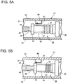
- the steering angle is 0°, as illustrated in FIG. 5A that illustrates the cylinder boot 50 disposed on the right side when viewed from the operator.
- the cylinder rod 47 is extended when the steering angle is 0°, and the flange portion 54 of the cylinder boot 50 is positioned on the right side (adjacent to the tie rod 44) of the detection sensor 60. Therefore, the detection sensor 60 does not detect the flange portion 54, which corresponds to the detection portion, and does not transmit a detection signal.
- the orientation of the sensor light emitted from the detection sensor 60 is indicated by an arrow.
- the cylinder rod 47 for steering the right steered wheel 14 contracts, and the associated flange portion 54 moves toward the cylinder body 46 with the contraction of the cylinder rod 47.
- the bellows-shaped cylindrical portion 56 is thus deformed to contract with the movement of the flange portion 54.
- the flange portion 54 approaches the detection sensor 60, and the detection sensor 60 detects the flange portion 54.
- the detection sensor 60 transmits a detection signal to the controller 22.
- the controller 22 detects that the steering angle has exceeded the predetermined steering angle.
- the other cylinder rod 47 for steering the left steered wheel 14 extends so that the left flange portion 54 approaches the left steered wheel 14 from the position of the flange portion 54 when the steering angle is 0°.
- the cylinder boot 50 according to the present embodiment has the following advantageous effects.
- the flange portion 54 has an outer peripheral surface 71 that is formed of a metal coating and corresponds to the detection surface of the present disclosure.
- the cylinder boot 70 according to another example 1 allows the detection sensor 60 to use a proximity sensor instead of an optical sensor.
- the outer peripheral surface 71 which is the detection surface, is made of metal, this configuration allows to use an inductive proximity sensor that detects magnetic loss caused by proximity of the outer peripheral surface 71.
- the cylinder boot 80 according to another example 2 illustrated in FIG. 6B has a projection portion 81 that corresponds to the detection portion of the present disclosure and is configured to face the detection sensor 60, instead of a flange portion formed on the circumference of the cylinder boot body 51 along the circumferential direction of the cylinder boot body 51.
- the projection portion 81 is formed on an outer peripheral surface of the cylinder boot body 51 adjacent to the rod-side fixing portion 52.
- the projection portion 81 is displaced in the axial direction of the cylinder rod 47 by the extension and contraction of the cylinder rod 47.
- the cylinder boot 80 according to another example 2 allows weight reduction and material reduction of the cylinder boot 80.
Landscapes
- Engineering & Computer Science (AREA)
- Mechanical Engineering (AREA)
- General Engineering & Computer Science (AREA)
- Transportation (AREA)
- Chemical & Material Sciences (AREA)
- Combustion & Propulsion (AREA)
- Physics & Mathematics (AREA)
- Structural Engineering (AREA)
- Fluid Mechanics (AREA)
- Civil Engineering (AREA)
- General Physics & Mathematics (AREA)
- Life Sciences & Earth Sciences (AREA)
- Geology (AREA)
- Steering-Linkage Mechanisms And Four-Wheel Steering (AREA)
- Vehicle Body Suspensions (AREA)
- Power Steering Mechanism (AREA)
- Sealing Devices (AREA)
- Diaphragms And Bellows (AREA)
Abstract
Description
- The present disclosure relates to a cylinder boot for an axle of an industrial vehicle.
- A cylinder cover for an industrial vehicle disclosed in
Japanese Patent Application Publication No. 2006-160151 Japanese Patent Application Publication No. 2006-160151 - According to the cylinder cover for an industrial vehicle disclosed in
Japanese Patent Application Publication No. 2006-160151 - Further,
Japanese Registered Utility Model No. 3144024 - However, the cylinder cover for an industrial vehicle disclosed in
Japanese Patent Application Publication No. 2006-160151 Japanese Registered Utility Model No. 3144024 - An industrial vehicle may detect whether the steering angle of a steered wheel has exceeded a threshold value. In this case, for example, as illustrated in
FIG. 7 , anbeam axle 92 of avehicle body 91 may be provided with adetection sensor 93, and adetection object 96 disposed on asteering knuckle 95 that is pivotable via aking pin 94. When acylinder rod 97 extends or contracts in response to the steering operation, thesteering knuckle 95 pivots so that thedetection sensor 93 detects thedetection object 96 and transmits a detection signal. This enables detection of whether or not the steering angle of the steered wheel has exceeded the threshold value. However, this configuration requires processing of thesteering knuckle 95 for mounting thedetection object 96 to thesteering knuckle 95 or addition of a member, such as a bracket, for mounting thedetection object 96. Thedetection sensor 93 and thedetection object 96 are provided at positions where they easily get dirty and are likely to interfere with foreign matters, such as a stone flying from the road surface. Further, the mounting structure of the cylinder boot ofJapanese Registered Utility Model No. 3144024 - The present disclosure, which has been made in light of the above-mentioned problem, is directed to providing a cylinder boot for an axle of an industrial vehicle, wherein the cylinder boot protects a cylinder rod and serves as a detection object used for detection of a steering angle.
- In accordance with an aspect of the present disclosure, there is provided a cylinder boot for an axle of an industrial vehicle. The industrial vehicle has a beam axle, a steering knuckle pivotably supported by the beam axle and a steering hydraulic cylinder supported by the beam axle. A cylinder rod of the steering hydraulic cylinder is connected to the steering knuckle to pivot the steering knuckle. The cylinder boot covers the cylinder rod of the steering hydraulic cylinder. The cylinder boot includes a cylinder boot body, a rod-side fixing portion, a cylinder-side fixing portion, and a detection portion. The cylinder boot body has a contractable portion that is contractable in response to a stroke of the cylinder rod. The rod-side fixing portion is fixed to a distal end portion of the cylinder rod. The cylinder-side fixing portion is fixed to a cylinder body of the steering hydraulic cylinder. The detection portion is displaced in a direction in which the cylinder rod extends or contracts, and is detected by a detection sensor disposed on the beam axle.
- Other aspects and advantages of the disclosure will become apparent from the following description, taken in conjunction with the accompanying drawings, illustrating by way of example the principles of the disclosure.
- The disclosure, together with objects and advantages thereof, may best be understood by reference to the following description of the embodiments together with the accompanying drawings in which:
-
FIG. 1 is a side view of a tow tractor according to an embodiment of the present disclosure; -
FIG. 2 is a front view of a front axle according to the embodiment of the present disclosure; -
FIG. 3 is a cross-sectional front view of a main part of the front axle according to the embodiment of the present disclosure; -
FIG. 4A is a perspective view of a cylinder boot according to the embodiment of the present disclosure, andFIG. 4B is a longitudinal cross-sectional view of the cylinder boot according to the embodiment of the present disclosure; -
FIG. 5A is a front view of the cylinder boot when the steering angle is 0°, andFIG. 5B is a front view of the cylinder boot when the detection sensor detects a flange portion; -
FIG. 6A is a perspective view of a cylinder boot according to another example 1, andFIG. 6B is a perspective view of a cylinder boot according to another example 2; and -
FIG. 7 is a front view illustrating a detection sensor of an beam axle and a detection object of a steering knuckle according to a conventional art. - A cylinder boot for an axle of an industrial vehicle according to an embodiment of the present disclosure will be described below with reference to the drawings. The present embodiment is an example of application to a tow tractor, which corresponds to the industrial vehicle of the present disclosure. The "front and rear", "right and left", and "up and down" described herein for specifying the direction are defined based on a state where the operator of the tow tractor is seated on a driver's seat of the driver's section and faces the forward side of the tow tractor.
- As illustrated in
FIG. 1 , a driver'ssection 12 is provided near the center of avehicle body 11 of atow tractor 10 that serves as a towing vehicle (i.e., the industrial vehicle of the present disclosure), and abattery 13 is accommodated in front of the driver'ssection 12 in thevehicle body 11. Steeredwheels 14 as front wheels are provided in a front portion of thevehicle body 11, and drivingwheels 15 as rear wheels are provided in a rear portion of thevehicle body 11. Thevehicle body 11 is provided with adriving motor 16 as a driving device that generates driving force for driving the vehicle. A power transmission mechanism (not illustrated) that transmits the driving force of the drivingmotor 16 to thedriving wheels 15 is provided between the drivingmotor 16 and thedriving wheels 15. Thetow tractor 10 of the present embodiment is a battery-type tow tractor that travels on the electric power of thebattery 13 mounted on thevehicle body 11. - The driver's
section 12 in thevehicle body 11 is provided with driver'sseats 17 arranged on the right and left.FIG. 1 illustrates only one of the driver'sseats 17. Asteering column 18 is provided in front of the driver'sseat 17. Asteering wheel 19 for changing the steering angle of the steeredwheels 14 is mounted on thesteering column 18. - An
accelerator pedal 21 is provided on a floor surface in front of the driver'sseat 17. Thetow tractor 10 controls driving of thedriving motor 16 to adjust the vehicle speed in response to the pressing amount of theaccelerator pedal 21 that is pressed down by the operator. Acontroller 22 that performs various controls of thetow tractor 10 is mounted below the driver'sseat 17 in thevehicle body 11. - A
drawbar device 24 that couples a towed vehicle, such as a wheeled platform, is provided in the rear portion of thevehicle body 11. Adrawbar operating lever 25 is provided behind the driver'sseat 17. Thedrawbar operating lever 25 is operated by the operator to cause the towed vehicle to be coupled to or decoupled from thedrawbar device 24. Thedrawbar operating lever 25 is provided within the reach of the operator's hand in a state that the operator is seated on the driver'sseat 17. - As illustrated in
FIG. 2 , thevehicle body 11 includes afront axle 26 in the front portion of thevehicle body 11, and thefront axle 26 includes the steeredwheels 14. Thefront axle 26 includes afront beam axle 27 that corresponds to the beam axle of the present disclosure and includes abase plate 31 extending in the right-left direction. Thebase plate 31 has anupper plate 32 and alower plate 33 respectively on the upper portion and the lower portion of thebase plate 31. Theupper plate 32 and thelower plate 33 are fixed to thebase plate 31 by welding, and a surface of theupper plate 32 and a surface of thelower plate 33 are parallel to each other. Thebase plate 31 has, in the front portion thereof, aconnection plate 34 that connects theupper plate 32 and thelower plate 33. The longitudinal direction of thefront beam axle 27 coincides with the width direction of thebase plate 31, and acenter pin 35 is inserted into the width center of thebase plate 31. Thefront beam axle 27 is coupled to thevehicle body 11 by thecenter pin 35. - The
front beam axle 27 is provided with a pair of steeringknuckles 36 that are respectively disposed at the right end and a left end of thefront beam axle 27. Each of the steeringknuckles 36 is supported by anupper boss portion 37 and alower boss portion 38 into which aking pin 39 inserted so that thesteering knuckle 36 is pivotable to the right and left via theking pin 39. That is, the steeringknuckles 36 is pivotably supported by thefront beam axle 27. The shapes of the pair of steeringknuckles 36 are symmetrical to each other. - As illustrated in
FIG. 3 , thesteering knuckle 36 has theking pin 39 extending in the up-down direction, awheel spindle 40 protruding outward from theking pin 39 in the right-left direction of thevehicle body 11, and aknuckle arm 41 protruding frontward. An upper end portion of theking pin 39 protrudes upward from thesteering knuckle 36, and a lower end portion of theking pin 39 protrudes downward from thesteering knuckle 36. Thewheel spindle 40 of thesteering knuckle 36 supports the associated steeredwheel 14 pivotally via ahub 42. Theknuckle arm 41 has a distal end to which one ends of a pair of upper andlower tie rods 44 are pivotally coupled via acoupling pin 43. Thetie rods 44 couple a steeringhydraulic cylinder 45, which will be described below, and thesteering knuckle 36. That is, thesteering knuckle 36 is connected to and pivoted by the steeringhydraulic cylinder 45. - As illustrated in
FIG. 2 , the steering hydraulic cylinder 45 (hereinafter simply referred to as "thehydraulic cylinder 45") is mounted to thefront beam axle 27. Thehydraulic cylinder 45 is a double-acting hydraulic cylinder that operates upon receiving supply of hydraulic oil in a hydraulic circuit (not illustrated). Thehydraulic cylinder 45 includes acylinder body 46 that is fixed to thebase plate 31 by a bolt or the like (not illustrated). The inside of thecylinder body 46 is partitioned into two chambers by a piston (not illustrated). The piston is coupled to right and leftcylinder rods 47 that respectively extend from the piston to the right and the left and protrude from thecylinder body 46. Thecylinder rods 47 extend and contract in the right-left direction by the operation of thehydraulic cylinder 45. Each of thecylinder rod 47 has adistal end portion 48 that is pivotally coupled to the other ends of thetie rods 44 via a coupling pin 49 (seeFIG. 3 ). - Each
cylinder rod 47 has acylinder boot 50 for a front axle (hereinafter simply referred to as "thecylinder boot 50"). Thecylinder boot 50 is mounted to thecylinder rod 47 to protect thecylinder rod 47. As illustrated inFIGS. 4A and 4B , thecylinder boot 50 includes acylinder boot body 51, a rod-side fixing portion 52, a cylinder-side fixing portion 53, and aflange portion 54. - The
cylinder boot body 51 is made of a rubber material and has flexibility. Thecylinder boot body 51 has acylindrical portion 55 covering thecylinder rod 47, and a bellows-shapedcylindrical portion 56 extending in an axial direction of the cylinder rod 47 (an axial center P direction) from an end portion of thecylindrical portion 55. The bellows-shapedcylindrical portion 56 serves as a contractable portion of thecylinder boot body 51, and is configured to absorb an extension stroke and a contraction stroke of thecylinder rod 47. In a state where thecylinder boot 50 is mounted on thecylinder rod 47, thecylindrical portion 55 is positioned adjacent to thedistal end portion 48, and the bellows-shapedcylindrical portion 56 is positioned adjacent to thecylinder body 46. - The rod-
side fixing portion 52 is disposed at one end portion of thecylinder boot body 51. The rod-side fixing portion 52 includes aring member 57 fixed to an inner peripheral surface of the one end portion of thecylinder boot body 51. Thedistal end portion 48 of thecylinder rod 47 is fixed to the rod-side fixing portion 52 by press-fitting (seeFIG. 3 ). As illustrated inFIG. 4B , the cylinder-side fixing portion 53 is disposed at one end portion of the bellows-shapedcylindrical portion 56, which serves as the other end portion of thecylinder boot body 51. The cylinder-side fixing portion 53 includes a lockingmember 58 that is capable of being fixed to an end portion of thecylinder body 46 adjacent to thecylinder rod 47. The lockingmember 58 is not illustrated inFIG. 4A . - The
flange portion 54 has an outer diameter that is larger than an outer diameter of thecylindrical portion 55, and is formed on radially outer portion of the rod-side fixing portion 52. Theflange portion 54 is formed on a circumference of thecylinder boot body 51 along a circumferential direction of thecylinder boot body 51. Theflange portion 54 is displaced by extension or contraction of thecylinder rod 47 in a direction (a direction of the axial center P) in which thecylinder rod 47 extends or contracts. Theflange portion 54 corresponds to a detection portion of the present disclosure that is detected by adetection sensor 60, which will be described below. Theflange portion 54 has areflection surface 59 for reflecting light on an outer peripheral surface thereof. - As illustrated in
FIG. 3 , thedetection sensor 60 is mounted on a lower surface of theupper plate 32 of thefront beam axle 27 via abracket 61 to detect that thecylinder rod 47 has exceeded a predetermined stroke. Thedetection sensor 60 is a reflective optical sensor and includes a light-emitting portion and a light-receiving portion (not illustrated) to detect theflange portion 54 in a non-contact manner. When theflange portion 54 is brought close to thedetection sensor 60 by the contraction of thecylinder rod 47, thereflection surface 59 of theflange portion 54 reflects a sensor light that is emitted from the light-emitting portion of thedetection sensor 60 so that the light-receiving portion of thedetection sensor 60 detects the reflected light and thus transmits a detection signal to thecontroller 22. - The extension and contraction of the
cylinder rod 47 is proportional to the steering angle of the steeredwheels 14, thecontroller 22, upon receiving the detection signal, detects that the steering angle has exceeded a predetermined steering angle. The mounting position of thedetection sensor 60 on theupper plate 32 only has to be determined relative to the position of theflange portion 54 so as to correspond to a predetermined steering angle for detection. - Next, the operation of the
cylinder boot 50 of the present embodiment will be described. When thetow tractor 10 travels in a straight line, the steering angle is 0°, as illustrated inFIG. 5A that illustrates thecylinder boot 50 disposed on the right side when viewed from the operator. Thecylinder rod 47 is extended when the steering angle is 0°, and theflange portion 54 of thecylinder boot 50 is positioned on the right side (adjacent to the tie rod 44) of thedetection sensor 60. Therefore, thedetection sensor 60 does not detect theflange portion 54, which corresponds to the detection portion, and does not transmit a detection signal. The orientation of the sensor light emitted from thedetection sensor 60 is indicated by an arrow. - Next, when the
hydraulic cylinder 45 is operated by leftward steering, thecylinder rod 47 for steering the right steeredwheel 14 contracts, and the associatedflange portion 54 moves toward thecylinder body 46 with the contraction of thecylinder rod 47. The bellows-shapedcylindrical portion 56 is thus deformed to contract with the movement of theflange portion 54. As illustrated inFIG. 5B , theflange portion 54 approaches thedetection sensor 60, and thedetection sensor 60 detects theflange portion 54. When thedetection sensor 60 detects theflange portion 54, thedetection sensor 60 transmits a detection signal to thecontroller 22. Upon receiving the detection signal, thecontroller 22 detects that the steering angle has exceeded the predetermined steering angle. When thecylinder rod 47 for steering the right steeredwheel 14 contracts, theother cylinder rod 47 for steering the left steeredwheel 14 extends so that theleft flange portion 54 approaches the left steeredwheel 14 from the position of theflange portion 54 when the steering angle is 0°. - The
cylinder boot 50 according to the present embodiment has the following advantageous effects. - (1) The
cylinder boot 50 covers the associatedcylinder rod 47 of the steeringhydraulic cylinder 45 to protect thecylinder rod 47. Thecylinder boot 50 includes theflange portion 54, which corresponds to the detection portion of the present disclosure, and thedetection sensor 60 provided on thefront beam axle 27 detects theflange portion 54 that is displaced by the extension and contraction of thecylinder rod 47. This configuration allows thecylinder boot 50 to serve as a detection object, which is detected by thedetection sensor 60, while surely protecting thecylinder rod 47. Therefore, this configuration eliminates the need for the provision of a detection object on thesteering knuckle 36 or the like, thereby enabling reduction of the number of components of thefront axle 26 and a space saving in thefront axle 26. - (2) The
flange portion 54 is formed on the circumference of thecylinder boot body 51 along the circumferential direction of thecylinder boot body 51. This configuration eliminates the need for alignment of theflange portion 54 with thecylinder rod 47 in the circumferential direction of thecylinder boot body 51 when thecylinder boot 50 is mounted to thecylinder rod 47. Even if thecylinder rod 47 rotates about the axial center P, this configuration allows theflange portion 54 to be detected by thedetection sensor 60. - (3) The
distal end portion 48 of thecylinder rod 47 is fixed to the rod-side fixing portion 52 by press-fitting. This configuration eliminates the need for a means or a member for fixing thedistal end portion 48 of thecylinder rod 47 to the rod-side fixing portion 52, thereby reducing the number of components of thefront axle 26. - (4) The
flange portion 54 is detected by thedetection sensor 60 in a non-contact manner. Therefore, theflange portion 54 is not brought into contact with thecylinder rod 47, and does not hinder extension and contraction of thecylinder rod 47. - (5) The
flange portion 54 has thereflection surface 59 that reflects the sensor light emitted from thedetection sensor 60. This allows thedetection sensor 60 to use a reflective optical sensor that emits a sensor light and detects the reflected sensor light. The provision of thereflection surface 59 allows the detection portion to be formed regardless of the material of thecylinder boot body 51. - (6) The
cylinder boot 50 includes theflange portion 54 that corresponds to the detection portion of the present disclosure, and thedetection sensor 60 is disposed in a space surrounded by theupper plate 32, thelower plate 33, and thebase plate 31 of thefront beam axle 27. This configuration allows thedetection sensor 60 and theflange portion 54 to be unlikely to get dirty and unlikely to interfere with foreign matters, such as a stone, which may fly toward them while the vehicle travels, thereby increasing the durability of thedetection sensor 60 and theflange portion 54. - Next, a
cylinder boot 70 according to another example 1 will be described. In thecylinder boot 70 according to another example 1 illustrated inFIG. 6A , theflange portion 54 has an outerperipheral surface 71 that is formed of a metal coating and corresponds to the detection surface of the present disclosure. Thecylinder boot 70 according to another example 1 allows thedetection sensor 60 to use a proximity sensor instead of an optical sensor. For example, since the outerperipheral surface 71, which is the detection surface, is made of metal, this configuration allows to use an inductive proximity sensor that detects magnetic loss caused by proximity of the outerperipheral surface 71. - Next, a
cylinder boot 80 according to another example 2 will be described. Thecylinder boot 80 according to another example 2 illustrated inFIG. 6B has aprojection portion 81 that corresponds to the detection portion of the present disclosure and is configured to face thedetection sensor 60, instead of a flange portion formed on the circumference of thecylinder boot body 51 along the circumferential direction of thecylinder boot body 51. Theprojection portion 81 is formed on an outer peripheral surface of thecylinder boot body 51 adjacent to the rod-side fixing portion 52. Theprojection portion 81 is displaced in the axial direction of thecylinder rod 47 by the extension and contraction of thecylinder rod 47. Thecylinder boot 80 according to another example 2 allows weight reduction and material reduction of thecylinder boot 80. - The present disclosure is not limited to the above embodiment (including the examples), and various modifications can be made within the scope of the gist of the disclosure, and for example, the following modifications may be made.
- ∘ In the above embodiment (including the examples), the detection portion and the rod-side fixing portion of the cylinder boot for an axle are located at substantially the same position in the axial direction of the cylinder rod. However, the present disclosure is not limited thereto. The detection portion and the rod-side fixing portion of the cylinder boot for an axle may be located at different positions in the axial direction of the cylinder rod.
- ∘ In the above embodiment (including the examples), the distal end portion of the cylinder rod of the cylinder boot for an axle is fixed to the rod-side fixing portion by press-fitting. However, the present disclosure is not limited thereto. The distal end portion of the cylinder rod of the cylinder boot for an axle may be fixed to the rod-side fixing portion, for example, by a bolt or a fixing means other than press-fitting.
- ∘ In the above embodiment (including the examples), the cylinder boot body includes the bellows-shaped cylindrical portion that corresponds to the contractable portion of the present disclosure. However, the present disclosure is not limited thereto. The contractable portion of the cylinder boot body may have any shape as long as the contractable portion can contract in response to the stroke of the cylinder rod. The contractable portion of the cylinder boot body may be formed by a part or the whole of the cylinder boot body.
- ∘ In the above embodiment (including the examples), the detection sensor detects the detection portion of the cylinder boot for an axle in a non-contact manner. However, the present disclosure is not limited thereto. The detection sensor may be a contact type sensor that comes into contact with the detection portion, such as a limit switch, to detect the detection portion.
- ∘ In the above embodiment (including the examples), the flange portion or the projection portion is formed integrally with the cylinder boot body. However, the present disclosure is not limited thereto. The flange portion or the projection portion may be a member that is formed separately from the cylinder boot body and may be attached to the cylinder boot body.
- ∘ The above embodiment (including the examples) mentions a tow tractor that corresponds to the industrial vehicle of the present disclosure. However, the industrial vehicle is not limited to a tow tractor, and may be, for example, a forklift. When a forklift serves as the industrial vehicle of the present disclosure, the cylinder boot for an axle of the present disclosure is mounted on a cylinder rod of a steering hydraulic cylinder of a rear axle of the forklift.
Claims (5)
- A cylinder boot (50, 70, 80) for an axle (26) of an industrial vehicle (10), the industrial vehicle (10) having a beam axle (27), a steering knuckle (36) pivotably supported by the beam axle (27) and a steering hydraulic cylinder (45) supported by the beam axle (27), a cylinder rod (47) of the steering hydraulic cylinder (45) being connected to the steering knuckle (36) to pivot the steering knuckle (36), wherein the cylinder boot (50, 70, 80) covers the cylinder rod (47) of the steering hydraulic cylinder (45), the cylinder boot (50, 70, 80) being characterized by:a cylinder boot body (51) that has a contractable portion (56) that is contractable in response to a stroke of the cylinder rod (47);a rod-side fixing portion (52) of the cylinder boot body (51) that is fixed to a distal end portion (48) of the cylinder rod (47);a cylinder-side fixing portion (53) of the cylinder boot body (51) that is fixed to a cylinder body (46) of the steering hydraulic cylinder (45); anda detection portion (54, 81) that is displaced in a direction in which the cylinder rod (47) extends or contracts, and is detected by a detection sensor (60) disposed on the beam axle (27).
- The cylinder boot (50, 70) for the axle (26) of the industrial vehicle (10) according to claim 1, characterized in that the detection portion (54) is formed on a circumference of the cylinder boot body (51) along a circumferential direction of the cylinder boot body (51).
- The cylinder boot (50, 70, 80) for the axle (26) of the industrial vehicle (10) according to claim 1 or 2, characterized in that the distal end portion (48) of the cylinder rod (47) is fixed to the rod-side fixing portion (52) by press-fitting.
- The cylinder boot (50, 70, 80) for the axle (26) of the industrial vehicle (10) according to any one of claims 1 to 3, characterized in that the detection portion (54, 81) is detected by the detection sensor (60) in a non-contact manner.
- The cylinder boot (70) for the axle (26) of the industrial vehicle (10) according to claim 4, characterized in that the detection portion (54) has a detection surface (71) that is formed of a metal coating.
Applications Claiming Priority (1)
| Application Number | Priority Date | Filing Date | Title |
|---|---|---|---|
| JP2020116801A JP7294257B2 (en) | 2020-07-07 | 2020-07-07 | Cylinder boots for industrial vehicle axles |
Publications (2)
| Publication Number | Publication Date |
|---|---|
| EP3936743A1 true EP3936743A1 (en) | 2022-01-12 |
| EP3936743B1 EP3936743B1 (en) | 2024-04-17 |
Family
ID=76483122
Family Applications (1)
| Application Number | Title | Priority Date | Filing Date |
|---|---|---|---|
| EP21179552.1A Active EP3936743B1 (en) | 2020-07-07 | 2021-06-15 | Cylinder boot for axle of industrial vehicle |
Country Status (4)
| Country | Link |
|---|---|
| US (1) | US11724541B2 (en) |
| EP (1) | EP3936743B1 (en) |
| JP (1) | JP7294257B2 (en) |
| CN (1) | CN113915192A (en) |
Citations (5)
| Publication number | Priority date | Publication date | Assignee | Title |
|---|---|---|---|---|
| DE102004030233A1 (en) * | 2004-06-23 | 2006-01-12 | Zf Lenksysteme Gmbh | Steering system for vehicle, has inductive sensor measuring movement of rod-like component relative to housing and formed by measuring coil and exciter coil that is arranged in axial area around measuring coil at housing |
| JP2006160151A (en) | 2004-12-09 | 2006-06-22 | Toyota Industries Corp | Cylinder cover for industrial vehicle and industrial vehicle |
| JP3144024U (en) | 2008-06-02 | 2008-08-14 | 株式会社豊田自動織機 | Cylinder boot mounting structure |
| JP2013133093A (en) * | 2011-12-27 | 2013-07-08 | Tcm Corp | Rod protective structure of hydraulic cylinder |
| EP3439151A1 (en) * | 2016-03-30 | 2019-02-06 | NTN Corporation | Electric actuator |
Family Cites Families (24)
| Publication number | Priority date | Publication date | Assignee | Title |
|---|---|---|---|---|
| DE2236379A1 (en) * | 1972-07-25 | 1974-02-14 | Volkswagenwerk Ag | STEERING DEVICE FOR VEHICLES, IN PARTICULAR MOTOR VEHICLES |
| JPS6037435A (en) * | 1983-08-08 | 1985-02-26 | Kayaba Ind Co Ltd | Hydraulic buffer |
| JPS6246266U (en) * | 1985-09-10 | 1987-03-20 | ||
| US5379856A (en) * | 1993-10-12 | 1995-01-10 | Trw Inc. | Rack and pinion steering gear assembly |
| DE19627893C1 (en) * | 1996-07-11 | 1997-11-13 | Daimler Benz Ag | Hydraulically operated steering for motor vehicles |
| US6220969B1 (en) * | 1998-08-14 | 2001-04-24 | St. Louis Stamping Inc. | Clampless universal joint and boot assembly |
| US6098742A (en) * | 1998-12-14 | 2000-08-08 | Trw Inc. | Steering apparatus |
| US6267395B1 (en) * | 1999-10-18 | 2001-07-31 | Durrell U. Howard | Vehicle steering compensator with air actuated trim mechanism |
| BR0003428A (en) * | 2000-07-28 | 2004-06-08 | Dana Ind S A | Spherical joint with pressure equalization system |
| US6550350B2 (en) * | 2001-06-13 | 2003-04-22 | Trw Inc. | Boot for a rack and pinion steering gear assembly |
| US6679504B2 (en) * | 2001-10-23 | 2004-01-20 | Liquidspring Technologies, Inc. | Seamless control of spring stiffness in a liquid spring system |
| US6817620B1 (en) * | 2002-08-02 | 2004-11-16 | Durrell U Howard | Precision steer wheel control system with internal solenoid |
| US7484743B2 (en) * | 2003-08-28 | 2009-02-03 | Iq Isolation Quality, Inc. | Hydraulic damper integrated into steering rack for attenuating steering nibble |
| JP2005083106A (en) * | 2003-09-10 | 2005-03-31 | Kobelco Contstruction Machinery Ltd | Working machine |
| US7967687B2 (en) * | 2005-09-01 | 2011-06-28 | Honda Motor Co., Ltd. | Joint structure and boot for joint |
| JP4319217B2 (en) * | 2006-12-27 | 2009-08-26 | 本田技研工業株式会社 | Telescopic actuator |
| JP5829133B2 (en) * | 2012-01-13 | 2015-12-09 | 日立オートモティブシステムズステアリング株式会社 | Power steering device |
| CN104144844B (en) * | 2012-02-29 | 2016-08-17 | 日立建机株式会社 | Vehicular steering apparatus |
| JP6037435B2 (en) | 2012-09-28 | 2016-12-07 | Kddi株式会社 | Video content distribution device |
| JP6104598B2 (en) * | 2012-12-19 | 2017-03-29 | Ntn株式会社 | Method for manufacturing outer joint member of constant velocity universal joint |
| JP6713314B2 (en) * | 2016-03-30 | 2020-06-24 | Ntn株式会社 | Electric actuator |
| JP6246266B2 (en) | 2016-06-08 | 2017-12-13 | 株式会社ルービックJp | Multilayer mattress |
| US10578213B2 (en) * | 2017-12-01 | 2020-03-03 | GM Global Technology Operations LLC | Steering assembly with dual wall boot |
| US11066099B2 (en) * | 2018-07-07 | 2021-07-20 | Marlin Crawler, Inc. | Methods and apparatus for moving the front wheels of a vehicle forward |
-
2020
- 2020-07-07 JP JP2020116801A patent/JP7294257B2/en active Active
-
2021
- 2021-06-15 EP EP21179552.1A patent/EP3936743B1/en active Active
- 2021-07-01 US US17/365,333 patent/US11724541B2/en active Active
- 2021-07-05 CN CN202110756207.1A patent/CN113915192A/en active Pending
Patent Citations (5)
| Publication number | Priority date | Publication date | Assignee | Title |
|---|---|---|---|---|
| DE102004030233A1 (en) * | 2004-06-23 | 2006-01-12 | Zf Lenksysteme Gmbh | Steering system for vehicle, has inductive sensor measuring movement of rod-like component relative to housing and formed by measuring coil and exciter coil that is arranged in axial area around measuring coil at housing |
| JP2006160151A (en) | 2004-12-09 | 2006-06-22 | Toyota Industries Corp | Cylinder cover for industrial vehicle and industrial vehicle |
| JP3144024U (en) | 2008-06-02 | 2008-08-14 | 株式会社豊田自動織機 | Cylinder boot mounting structure |
| JP2013133093A (en) * | 2011-12-27 | 2013-07-08 | Tcm Corp | Rod protective structure of hydraulic cylinder |
| EP3439151A1 (en) * | 2016-03-30 | 2019-02-06 | NTN Corporation | Electric actuator |
Also Published As
| Publication number | Publication date |
|---|---|
| US11724541B2 (en) | 2023-08-15 |
| US20220009282A1 (en) | 2022-01-13 |
| CN113915192A (en) | 2022-01-11 |
| EP3936743B1 (en) | 2024-04-17 |
| JP7294257B2 (en) | 2023-06-20 |
| JP2022014492A (en) | 2022-01-20 |
Similar Documents
| Publication | Publication Date | Title |
|---|---|---|
| US5813684A (en) | Front wheel suspension for a motorcycle | |
| US6227304B1 (en) | Upper hitch link | |
| US7693632B2 (en) | Motorcycle | |
| US6390764B1 (en) | Vehicle operable as both a lifting machine and an agricultural tractor | |
| AU2004298496B2 (en) | Steerable axle automatic lift sensor system | |
| JP5270331B2 (en) | Stroke amount detector | |
| US7900743B2 (en) | Electric power steering system for vehicle and utility vehicle therewith | |
| EP3936743B1 (en) | Cylinder boot for axle of industrial vehicle | |
| US20110001299A1 (en) | Vehicle having an axle capable of pendulum motion | |
| EP1327602A1 (en) | Working vehicle with transverse travel system | |
| US4236728A (en) | Apparatus for caster adjustment | |
| US7766709B2 (en) | Amphibious vehicle steering | |
| EP1825735B1 (en) | Motor-vehicle, in particular a tractor, provided with a front steerable device | |
| US20220275603A1 (en) | Implement connection system and vehicle having same | |
| CN114938642A (en) | Sensor device for a tractor of a trailer vehicle and trailer vehicle having such a sensor device | |
| JP2535928Y2 (en) | Small electric car | |
| CN219929541U (en) | Rear axle aligning sensor mechanism of telescopic arm forklift | |
| JP2023121894A (en) | Automatic traveling vehicle | |
| JP4070670B2 (en) | Industrial vehicle | |
| JP2001233235A (en) | Steering device for industrial vehicle | |
| JP3823652B2 (en) | Rearview mirror device | |
| JPS6040369Y2 (en) | Automobile front wheel entrapment prevention device | |
| JPH0446774B2 (en) | ||
| JP5781656B2 (en) | Self-propelled vehicle | |
| JP3893505B2 (en) | Vehicle steering system |
Legal Events
| Date | Code | Title | Description |
|---|---|---|---|
| PUAI | Public reference made under article 153(3) epc to a published international application that has entered the european phase |
Free format text: ORIGINAL CODE: 0009012 |
|
| STAA | Information on the status of an ep patent application or granted ep patent |
Free format text: STATUS: REQUEST FOR EXAMINATION WAS MADE |
|
| 17P | Request for examination filed |
Effective date: 20210615 |
|
| AK | Designated contracting states |
Kind code of ref document: A1 Designated state(s): AL AT BE BG CH CY CZ DE DK EE ES FI FR GB GR HR HU IE IS IT LI LT LU LV MC MK MT NL NO PL PT RO RS SE SI SK SM TR |
|
| B565 | Issuance of search results under rule 164(2) epc |
Effective date: 20211124 |
|
| P01 | Opt-out of the competence of the unified patent court (upc) registered |
Effective date: 20230519 |
|
| REG | Reference to a national code |
Ref document number: 602021011812 Country of ref document: DE Ref country code: DE Ref legal event code: R079 Free format text: PREVIOUS MAIN CLASS: F16J0003040000 Ipc: B62D0015020000 |
|
| GRAP | Despatch of communication of intention to grant a patent |
Free format text: ORIGINAL CODE: EPIDOSNIGR1 |
|
| STAA | Information on the status of an ep patent application or granted ep patent |
Free format text: STATUS: GRANT OF PATENT IS INTENDED |
|
| RIC1 | Information provided on ipc code assigned before grant |
Ipc: F16J 15/56 20060101ALI20231101BHEP Ipc: F16J 15/52 20060101ALI20231101BHEP Ipc: F16J 3/04 20060101ALI20231101BHEP Ipc: B62D 7/16 20060101ALI20231101BHEP Ipc: B62D 15/02 20060101AFI20231101BHEP |
|
| INTG | Intention to grant announced |
Effective date: 20231117 |
|
| GRAS | Grant fee paid |
Free format text: ORIGINAL CODE: EPIDOSNIGR3 |
|
| GRAA | (expected) grant |
Free format text: ORIGINAL CODE: 0009210 |
|
| STAA | Information on the status of an ep patent application or granted ep patent |
Free format text: STATUS: THE PATENT HAS BEEN GRANTED |
|
| AK | Designated contracting states |
Kind code of ref document: B1 Designated state(s): AL AT BE BG CH CY CZ DE DK EE ES FI FR GB GR HR HU IE IS IT LI LT LU LV MC MK MT NL NO PL PT RO RS SE SI SK SM TR |
|
| REG | Reference to a national code |
Ref country code: GB Ref legal event code: FG4D |
|
| REG | Reference to a national code |
Ref country code: CH Ref legal event code: EP |
|
| REG | Reference to a national code |
Ref country code: DE Ref legal event code: R096 Ref document number: 602021011812 Country of ref document: DE |
|
| REG | Reference to a national code |
Ref country code: IE Ref legal event code: FG4D |