EP3936718A1 - Wind turbine and retrofitting system and method for at least one wind turbine - Google Patents
Wind turbine and retrofitting system and method for at least one wind turbine Download PDFInfo
- Publication number
- EP3936718A1 EP3936718A1 EP20185265.4A EP20185265A EP3936718A1 EP 3936718 A1 EP3936718 A1 EP 3936718A1 EP 20185265 A EP20185265 A EP 20185265A EP 3936718 A1 EP3936718 A1 EP 3936718A1
- Authority
- EP
- European Patent Office
- Prior art keywords
- wind turbine
- marking light
- controller
- air traffic
- detection signal
- Prior art date
- Legal status (The legal status is an assumption and is not a legal conclusion. Google has not performed a legal analysis and makes no representation as to the accuracy of the status listed.)
- Pending
Links
Images


Classifications
-
- F—MECHANICAL ENGINEERING; LIGHTING; HEATING; WEAPONS; BLASTING
- F03—MACHINES OR ENGINES FOR LIQUIDS; WIND, SPRING, OR WEIGHT MOTORS; PRODUCING MECHANICAL POWER OR A REACTIVE PROPULSIVE THRUST, NOT OTHERWISE PROVIDED FOR
- F03D—WIND MOTORS
- F03D80/00—Details, components or accessories not provided for in groups F03D1/00 - F03D17/00
- F03D80/10—Arrangements for warning air traffic
-
- F—MECHANICAL ENGINEERING; LIGHTING; HEATING; WEAPONS; BLASTING
- F05—INDEXING SCHEMES RELATING TO ENGINES OR PUMPS IN VARIOUS SUBCLASSES OF CLASSES F01-F04
- F05B—INDEXING SCHEME RELATING TO WIND, SPRING, WEIGHT, INERTIA OR LIKE MOTORS, TO MACHINES OR ENGINES FOR LIQUIDS COVERED BY SUBCLASSES F03B, F03D AND F03G
- F05B2230/00—Manufacture
- F05B2230/80—Repairing, retrofitting or upgrading methods
-
- Y—GENERAL TAGGING OF NEW TECHNOLOGICAL DEVELOPMENTS; GENERAL TAGGING OF CROSS-SECTIONAL TECHNOLOGIES SPANNING OVER SEVERAL SECTIONS OF THE IPC; TECHNICAL SUBJECTS COVERED BY FORMER USPC CROSS-REFERENCE ART COLLECTIONS [XRACs] AND DIGESTS
- Y02—TECHNOLOGIES OR APPLICATIONS FOR MITIGATION OR ADAPTATION AGAINST CLIMATE CHANGE
- Y02E—REDUCTION OF GREENHOUSE GAS [GHG] EMISSIONS, RELATED TO ENERGY GENERATION, TRANSMISSION OR DISTRIBUTION
- Y02E10/00—Energy generation through renewable energy sources
- Y02E10/70—Wind energy
- Y02E10/72—Wind turbines with rotation axis in wind direction
-
- Y—GENERAL TAGGING OF NEW TECHNOLOGICAL DEVELOPMENTS; GENERAL TAGGING OF CROSS-SECTIONAL TECHNOLOGIES SPANNING OVER SEVERAL SECTIONS OF THE IPC; TECHNICAL SUBJECTS COVERED BY FORMER USPC CROSS-REFERENCE ART COLLECTIONS [XRACs] AND DIGESTS
- Y02—TECHNOLOGIES OR APPLICATIONS FOR MITIGATION OR ADAPTATION AGAINST CLIMATE CHANGE
- Y02P—CLIMATE CHANGE MITIGATION TECHNOLOGIES IN THE PRODUCTION OR PROCESSING OF GOODS
- Y02P70/00—Climate change mitigation technologies in the production process for final industrial or consumer products
- Y02P70/50—Manufacturing or production processes characterised by the final manufactured product
Definitions
- the invention concerns a wind turbine, comprising:
- Wind turbines are often tall structures that, at least if a certain height is surpassed, according to many legislations have to be marked by marking lights (warning lights) for air traffic.
- marking lights warning lights
- Such a marking light system comprises at least one marking light, which may also be called warning light and may, for example, emit bright red light to warn pilots of aircrafts that a tall structure is present.
- marking light systems usually additionally comprise sensory equipment, for example at least one light sensor, such that the at least one marking light may be turned on as soon as a certain level of darkness has set in.
- a controller of the marking light system evaluates data from at least one data source, in particular the sensor data of the at least one light sensor, and controls the at least one marking light accordingly.
- the brightness of the at least one marking light may also be controlled according to the level of ambient light measured by the at least one light sensor, but preferably due to other data. For example regarding a visibility range.
- the at least one warning light is turned off again once a certain level of ambient light is re-established, for example during dawn.
- marking lights may impose further restrictions on the use of marking lights.
- a law was passed that marking lights in wind turbines are only allowed to be activated when there actually is air traffic, in particular approaching air traffic, in a certain area around the wind turbine. In this manner, light pollution during night time shall be reduced to increase acceptance of wind turbines in the general public.
- air traffic detection systems which may be at least partly installed in the wind turbine itself and/or at least partly installed external to the wind turbine, may comprise at least one sensor for detecting air traffic.
- the sensor of the air traffic detection system may be at least one radar sensor scanning the airspace around the wind turbine, and/or may be adapted to receive predefined transponder signals from aircrafts in the airspace around the wind turbine. That is, air traffic detection systems may be radar-based and/or transponder-based, respectively.
- air traffic detection systems may be installed for and/or associated with multiple wind turbines, for example in a wind park. In any case, the air traffic detection system provides an air traffic detection signal, in the following briefly "detection signal", which has to be evaluated in the wind turbine to only activate the marking lights when air traffic has been detected in the area around the wind turbine, in particular approaching air traffic.
- the marking light controller may at least be configured to receive an input for modifying the brightness of the marking lights, for example from a wind turbine controller evaluating measurement data received from a visibility measurement device, wherein the visibility measurement device serves for judging a current visibility range, for example due to weather effects.
- the wind turbine as initially described, according to the invention further comprises a switching arrangement comprising at least one switching unit in the power line or the control line, wherein the switching unit is configured to receive the detection signal from an air traffic detection system associated with the wind turbine and to turn the marking lights on or off when the detection signal indicates air traffic or no air traffic, respectively, in an area around the wind turbine.
- the wind turbine controller may be any (already installed) control device of the wind turbine, preferably a main and/or master controller.
- the wind turbine may comprise at least one component thereof or even the whole air traffic detection system.
- at least one air traffic detection device may be provided for multiple wind turbines, wherein each wind turbine, in particular as part of the switching arrangement, may comprise a receiver for the detection signal, which may be by wire and/or wirelessly transmitted to each wind turbine from the air traffic detection system.
- the air traffic detection system which is associated with multiple wind turbines, may also determine wind turbine specific detection signals, each referring to a respective area around the wind turbine.
- the wind park may also be treated as one entity with a defined area in which, in particular approaching, air traffic is relevant, such that marking lights of the whole wind park may be turned on/off based on the same detection signal supplied to all wind turbines.
- the basic idea underlying the invention is to be able to retrofit wind turbines to also take the detection signal into account when controlling the at least one marking light, such that no components of the wind turbine need to be exchanged, but only the switching arrangement needs to be added.
- the power line and/or the control line are implemented as cables, these may have to be replaced by two cables or cut to permit positioning the switching unit in the respective line.
- the switching unit being in the power line means that the power line and thus power supply for the at least one marking light may be interrupted and re-connected by the switching unit.
- the switching unit being in the control line means that control signals, in particular brightness signals, may either be simply forwarded to the marking light controller or switched, in this case modified, to a state indicating that the at least one marking light is turned off.
- the switching unit in both cases serves to switch off the at least one marking light when no air traffic is detected in the area around the wind turbine.
- the switching arrangement thus works independently from any of the other systems but ensures that the at least one marking light can only be turned on when air traffic, in particular approaching air traffic, has been detected in the area around the wind turbine, as described by the detection signal.
- the marking light system nor other components of the wind turbine, in particular the wind turbine controller need to be modified in any way.
- the wind turbine is simply retrofit by a switching arrangement, which is either configured to interrupt the power supply to the at least one marking light or modify control signals, in particular brightness signals, from the wind turbine controller to the marking light controller such that the at least one marking light is not switched on unless the detection signal indicates relevant air traffic.
- the switching arrangement receives its input, namely the detection signal, from the air traffic detection system, such that it may be assured that the at least one marking light is not active anymore when no aircraft is within range.
- a wind turbine retrofitting system according to the invention which comprises the switching arrangement and may, in some cases, additionally comprise at least one component of the air traffic detection system, is very versatile and therefore integrable into many different types of wind turbines, in particular platforms and/or components, since these do not need to be modified. In particular, it is possible to fulfil legislation requirements without the need to update the wind turbine controller at all.
- the switching unit may be a relay in the power line, in particular using the detection signal as the switching control signal.
- This first alternative is, of course, applicable in any wind turbine which uses a power line to supply electrical power to the at least one marking light, in particular also other components of the marking light system and/or the whole marking light system.
- a simple relay can be used, which uses the detection signal, which may, in particular, be binary, indicating relevant traffic or no relevant traffic, as the switching signal, wherein, preferably, the relay may be in a powerless, open state as long as no relevant air traffic is detected in the area around the wind turbine.
- the detection signal used as a switching signal in this case, may have zero or at least very low voltage as long as it indicates no relevant air traffic.
- the detection signal may indicate this by being a direct current of higher voltage, such that the relay may be switched into the closed position and the at least one marking light may be lit according to data from the data source, in particular light sensor data.
- the marking light controller may be configured to generate an error signal to the wind turbine controller if it detects power disruption to the at least one marking light, since this is perceived as a fault condition by the manufacturer of the marking light system.
- the marking light controller may be configured to generate an error signal to the wind turbine controller if it detects power disruption to the at least one marking light, since this is perceived as a fault condition by the manufacturer of the marking light system.
- a power disruption to the at least one marking light caused by the switching unit is not a fault, but a desired effect.
- the switching arrangement additionally comprises a control unit receiving the error signal and the detection signal and configured to only forward the error signal when the error signal is not caused by switching activity of the switching unit, in particular when the detection signal indicates air traffic in the area around the wind turbine. That is, in particular, the control unit may be installed in the control line and may also receive the detection signal from the air traffic detection system.
- the detection signal indicates no air traffic in the area around the wind turbine and the control unit receives an error signal due to the relay being open, this error signal may be suppressed/deleted, such that it is not received by the wind turbine controller which does not have to be configured to handle it.
- the input from the air traffic detection system that is, the detection signal, can be used to disable error messages created by the marking light controller if the marking light controller switches on the at least one marking light, but does not receive the corresponding feedback, since the electrical power to the at least one marking light is not available because no aircraft is in range.
- the control unit may be understood as a man in the middle, being installed in the control line between the marking light controller and the wind turbine controller. Output and/or input signals coming from the marking light controller and/or vice versa can be, at least partially, fed into the control unit analyzing, as a man in the middle, the signals according to desired functionalities and, in particular, forwarding them only if, for example, a real system problem occurred and not a fault caused by an interaction of the switching arrangement.
- the control unit is configured to only block error signals relating to power disruption events depending on the detection signal. In this manner, actual fault conditions not caused by the switching arrangement may still be duly reported to the wind turbine controller.
- the detection signal may be received by the control unit and forwarded to the switching unit, in particular modified and/or converted by the control unit.
- the control unit of the switching arrangement may even comprise a wireless receiver for the detection signal of the, in particular externally installed, air traffic detection system.
- the detection signal may be modified and/or converted and then be forwarded to the switching unit, such that it can preferably directly be used as a switching signal for the relay.
- the in particular digital detection signal received in the control unit can be converted to a binary detection signal, having a low voltage when no air traffic is detected in the area around the wind turbine, and a high voltage, if air traffic has been detected in the area around the wind turbine.
- the wind turbine controller may also receive the detection signal and may be configured to discard the error signal when the detection signal indicates no air traffic in the area around the wind turbine. This, however, is less preferred since it would require a modification of the wind turbine controller.
- the switching unit may be a control unit in the control line, which is configured to modify the brightness signal to turn off the at least one marking light when the detection signal indicates no air traffic in the area around the wind turbine. That is, in particular, the brightness is set to zero as long as no air traffic in the area around the wind turbine is indicated by the detection signal. If, in some embodiments, the marking light controller accepts external input regarding brightness of the at least one marking light, such input may thus be modified to switch off the at least one marking light without the need to modify any other component of the wind turbine. In this case, the switching unit is the control unit installed in the control line to, again like a man in the middle, modify at least the brightness signals according to the detection signal. In this second alternative, no relay is needed, such that a very low-cost and simple alternative is provided.
- control unit may be understood as being or comprising an additional I/O board providing additional inputs and/or outputs, at least one input relating to the detection signal. At least a part of other signals input into the control unit may be modified and/or discarded depending on the detection signal, as described.
- the wind turbine may further comprise a visibility measuring device, wherein the wind turbine controller is configured to generate the brightness signal based on measurement data received from the visibility measurement device.
- the visibility measuring device may measure weather effects which may increase or decrease visibility range to accordingly provide brighter or less brighter warning by the at least one marking light.
- the brightness signal may also be additionally or alternatively derived from other information, for example from a current local time in correlation with the date and sun information.
- the air traffic detection system may comprise at least one radar sensor and/or at least one transponder signal receiver. That is, the air traffic detection system may be radar-based and/or transponder-based, as already explained. Of course, also other air traffic detection systems may be used, for example, air traffic detection systems using information provided by an air space control center and the like.
- the retrofitting system comprises:
- the wind turbine analogously apply to the retrofitting system according to the invention, with which wind turbines may be retrofitted without having to exchange their marking light system or to modify their wind turbine controller, to only use marking lights when air traffic is detected in the area around the wind turbine.
- the air traffic detection system may also be partly or entirely installed externally to the wind turbine, or as a part of the wind turbine, as discussed above.
- the retrofitting system can be used in a method for retrofitting at least one wind turbine, comprising
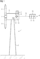
- Fig. 1 is a principle drawing of a wind turbine 1 according to the invention.
- the wind turbine 1 comprises a tower 2 onto which a nacelle 3 is rotatably mounted.
- a generator of the wind turbine 1 (not shown) may be housed among other components.
- a hub 4 to which, in this case, three wind turbine blades 5 are mounted, is rotatably connected to the nacelle 3.
- the wind turbine 1 comprises a marking light system 6 having at least one marking light 7, in this case installed, in this example, at the rear of the nacelle 3.
- the wind turbine 1 further comprises a wind turbine controller 8 communicating with the marking light system 6 via a control line, wherein the wind turbine controller 8 may, for example, be a main and/or master controller of the wind turbine 1.
- the marking light system 6 comprises light sensors as a data source, wherein the at least one marking light 7 may be turned on or off depending on sensor data of the at least one light sensor by a marking system controller, which is connected via the control line to the wind turbine controller 8.
- the wind turbine controller 8 may also be sending brightness signals governing the brightness of the at least one marking light 7 via the control line, for example depending on measurement data of a visibility measuring device, current time and/or date and sun information, and the like.
- the wind turbine 1, however, has been retrofitted using a retrofitting system 9 according to the invention to only activate the marking lights 7 when an aircraft is detected in an area around the wind turbine 1.
- the retrofitting system comprises an air traffic detection system 10 which may be radar-based, i.e. comprising at least one radar sensor 11, or transponder-based, i.e. comprising at least one transponder signal receiver 12.
- the air traffic detection system 10 may be at least partially installed in the wind turbine 1, but can also be at least partially provided externally to the wind turbine 1, in particular, if it is used for multiple wind turbines 1, in particular in a wind park.
- the retrofitting system 9 further comprises a switching arrangement 13 which has been installed in the nacelle 3 of the wind turbine 1 without the need to modify the marking light system 6 or the wind turbine controller 8, as will be further discussed with regard to the concrete embodiments in figs. 2, 3 and 4 .
- the switching arrangement 13 receives a detection signal from the air traffic detection system 10 indicating whether or not air traffic has been detected in the area around the wind turbine 1.
- the switching arrangement 13 keeps the at least one marking light 7 turned off as long as the detection signal indicates no air traffic detected in the area around the wind turbine.
- Fig. 2 shows the control configuration used in a first, simple embodiment of the invention.
- the at least one marking light 7 is not only connected to the marking light controller 15 of the marking light system 6, to which also the at least one light sensor 16 is connected as a data source, but is also connected to an electrical power supply via a power line 17.
- the marking light controller 15 is connected to the wind turbine controller 8 via a control line 18.
- the switching arrangement 13 comprises a switching unit 19, in this case a relay 20, installed in the power line 17 and adapted to interrupt or connect the power line 17 and thus the power supply to the at least one marking light 7.
- the switching unit 19 uses the detection signal, indicated by arrow 21, as a binary signal, which is of a low voltage if no aircraft has been detected in the area around the wind turbine 1. In this state, the relay 20 is open and the power supply to the at least one marking light 7 is interrupted. That is, even if the marking light controller 15 tries to turn on the at least one marking light 7, it will not shine, since no electrical power is available.
- the detection signal supplied to the relay 20 is of a high voltage such that the relay 20 closes and the at least one marking light 7 can be turned on and off by the marking light controller 15 as known.
- the marking light controller 15 will send an error signal to the wind turbine controller 8 when a power disruption to the at least one marking light 7 is detected, in particular also if this is caused by the switching unit 19.
- the control unit 22 is now installed in the control line 18 and receives error signals according to arrow 24 from the marking light controller 15. If the error signal describes power interruption and the detection signal, which is again received according to arrow 23 from the air traffic detection system 10, converted and forwarded according to arrow 21 to the relay 20, indicates air traffic in the area around the wind turbine 1, the error signal is not forwarded to the wind turbine controller 8.
- the control unit 22 only forwards the error signal to the wind turbine controller 8 if the detection signal indicates air traffic in the area around the wind turbine 1, as indicated by dashed arrow 25.
- the detection signal indicates no air traffic detected in the area around the wind turbine 1, the power disruption has been caused by the switching arrangement 13 itself and the error signal is thus suppressed/deleted.
- Other error signals are, of course, forwarded to the wind turbine controller 8 without modification, if they are not caused by switching activity of the switching unit 19. It is, however noted, that while it is expedient to use the detection signal to describe switching activity as the cause of the error signal, other signal indicating the switching activity of the switching unit 19 may also be used.
- fig. 3 also indicates, see arrow 26, 27, the possibility of control signals, in particular brightness signals, from the wind turbine controller 8 to the marking light controller 15, which are simply forwarded or not even touched by the control unit 22.
- Fig. 4 shows a third embodiment in which the control unit 22 of the switching arrangement 13, which is again installed in the control line 18, is used as the switching unit 19 since the wind turbine controller 8 supplies brightness signals according to arrow 26 and 27 to the marking light controller 15, for example according to measurement data from a visibility measurement device 28.
- the control unit 22 is configured to modify the brightness signals received according to arrow 26 to set the brightness to zero, that is, turn the at least one marking light 7 off, if the detection signal, again provided according to arrow 23, indicates no air traffic in the area around the wind turbine 1. Only if air traffic is indicated in the area around the wind turbine 1, the brightness signals are forwarded unmodified, as indicated by the dashed line of arrow 27.
- control unit 22 may also configured to suppress such signals if the detection signal 23 indicates no air traffic in the area around the wind turbine 1.
- the power line 17 is unmodified.
- Fig. 5 illustrates how an air traffic detection system 10 can be associated with multiple wind turbines 1 by providing the detection signal according to arrows 23 to the switching arrangements 13 of each of those wind turbines 1.
Abstract
Wind turbine (1) comprising:
- a marking light system (6) comprising at least one marking light (7) for aerial traffic, a data source, in particular at least one light sensor (16), and a marking light controller (15) for controlling the at least one marking light (7) according to data of the data source, in particular sensor data of the at least one light sensor (16),
- a wind turbine controller (8),
- a power line (17) for at least the at least one marking light (7) and/or at least one control line (18) connecting the marking light controller (15) to the wind turbine controller (8),
wherein the wind turbine (1) further comprises a switching arrangement (13) comprising at least one switching unit (19) in the power line (17) or the control line (18), wherein the switching unit (19) is configured to receive a detection signal from an air traffic detection system (10) associated with the wind turbine (1) and to turn the at least one marking light (7) on or off when the detection signal indicates air traffic or no air traffic, respectively, in an area around the wind turbine (1).
Description
- The invention concerns a wind turbine, comprising:
- a marking light system comprising at least one marking light for aerial traffic, a data source, in particular at least one light sensor, and a marking light controller for controlling the at least one marking light according to data of the data source,
- a wind turbine controller, and
- a power line for at least the at least one marking light and/or at least one control line connecting the marking light controller to the wind turbine controller.
- Wind turbines are often tall structures that, at least if a certain height is surpassed, according to many legislations have to be marked by marking lights (warning lights) for air traffic. Hence, many wind turbines have been equipped with marking light systems, which may also be called obstruction lighting system or obstacle lighting system. Such a marking light system comprises at least one marking light, which may also be called warning light and may, for example, emit bright red light to warn pilots of aircrafts that a tall structure is present. Known marking light systems usually additionally comprise sensory equipment, for example at least one light sensor, such that the at least one marking light may be turned on as soon as a certain level of darkness has set in. A controller of the marking light system evaluates data from at least one data source, in particular the sensor data of the at least one light sensor, and controls the at least one marking light accordingly. In some cases, the brightness of the at least one marking light may also be controlled according to the level of ambient light measured by the at least one light sensor, but preferably due to other data. For example regarding a visibility range. Of course, the at least one warning light is turned off again once a certain level of ambient light is re-established, for example during dawn.
- However, legislative bodies of some countries, in particular in the future, may impose further restrictions on the use of marking lights. For example, in Germany, a law was passed that marking lights in wind turbines are only allowed to be activated when there actually is air traffic, in particular approaching air traffic, in a certain area around the wind turbine. In this manner, light pollution during night time shall be reduced to increase acceptance of wind turbines in the general public.
- To adapt the functionality of wind turbines regarding such new requirements, air traffic detection systems have already been proposed in the state of the art. Such air traffic detection systems, which may be at least partly installed in the wind turbine itself and/or at least partly installed external to the wind turbine, may comprise at least one sensor for detecting air traffic. For example, the sensor of the air traffic detection system may be at least one radar sensor scanning the airspace around the wind turbine, and/or may be adapted to receive predefined transponder signals from aircrafts in the airspace around the wind turbine. That is, air traffic detection systems may be radar-based and/or transponder-based, respectively. Such air traffic detection systems may be installed for and/or associated with multiple wind turbines, for example in a wind park. In any case, the air traffic detection system provides an air traffic detection signal, in the following briefly "detection signal", which has to be evaluated in the wind turbine to only activate the marking lights when air traffic has been detected in the area around the wind turbine, in particular approaching air traffic.
- However, known marking light systems, which are installed in wind turbines, often neither provide additional interfaces for external input, in this case the detection signal, nor are the controllers adapted to be re-programmed, in this case for additionally taking the detection signal into account. In such cases, the complete marking light system would have to be exchanged to ensure compatibility with current or future laws. In some marking light systems, the marking light controller may at least be configured to receive an input for modifying the brightness of the marking lights, for example from a wind turbine controller evaluating measurement data received from a visibility measurement device, wherein the visibility measurement device serves for judging a current visibility range, for example due to weather effects. While it may be in principle possible to supply the detection signal from the air traffic detection system to the wind turbine controller, which modifies the brightness signal to the marking light controller accordingly, this would require sophisticated and effortful reprogramming of the wind turbine controller, which is undesired and takes a long time.
- It is an object of the current invention to provide a simple way to adapt a wind turbine with low expenditure to switch marking lights according to the detection signal of an air traffic device.
- This object is achieved by providing a wind turbine, a retrofitting system and a method for retrofitting at least one wind turbine according to the independent claims. Advantageous embodiments are described by the dependent claims.
- The wind turbine as initially described, according to the invention, further comprises a switching arrangement comprising at least one switching unit in the power line or the control line, wherein the switching unit is configured to receive the detection signal from an air traffic detection system associated with the wind turbine and to turn the marking lights on or off when the detection signal indicates air traffic or no air traffic, respectively, in an area around the wind turbine.
- The wind turbine controller may be any (already installed) control device of the wind turbine, preferably a main and/or master controller. Regarding the air traffic detection system, the wind turbine may comprise at least one component thereof or even the whole air traffic detection system. However, in particular for wind parks comprising multiple wind turbines, at least one air traffic detection device may be provided for multiple wind turbines, wherein each wind turbine, in particular as part of the switching arrangement, may comprise a receiver for the detection signal, which may be by wire and/or wirelessly transmitted to each wind turbine from the air traffic detection system. In particular, the air traffic detection system, which is associated with multiple wind turbines, may also determine wind turbine specific detection signals, each referring to a respective area around the wind turbine. In other embodiments, however, the wind park may also be treated as one entity with a defined area in which, in particular approaching, air traffic is relevant, such that marking lights of the whole wind park may be turned on/off based on the same detection signal supplied to all wind turbines.
- The basic idea underlying the invention is to be able to retrofit wind turbines to also take the detection signal into account when controlling the at least one marking light, such that no components of the wind turbine need to be exchanged, but only the switching arrangement needs to be added. However, if the power line and/or the control line are implemented as cables, these may have to be replaced by two cables or cut to permit positioning the switching unit in the respective line. The switching unit being in the power line means that the power line and thus power supply for the at least one marking light may be interrupted and re-connected by the switching unit. The switching unit being in the control line means that control signals, in particular brightness signals, may either be simply forwarded to the marking light controller or switched, in this case modified, to a state indicating that the at least one marking light is turned off. That is, whether the switching unit is installed in the power line or in the signal line, it in both cases serves to switch off the at least one marking light when no air traffic is detected in the area around the wind turbine. The switching arrangement thus works independently from any of the other systems but ensures that the at least one marking light can only be turned on when air traffic, in particular approaching air traffic, has been detected in the area around the wind turbine, as described by the detection signal. Preferably, thus, to retrofit a wind turbine to also account for the presence of air traffic around the wind turbine, neither the marking light system nor other components of the wind turbine, in particular the wind turbine controller, need to be modified in any way. The wind turbine is simply retrofit by a switching arrangement, which is either configured to interrupt the power supply to the at least one marking light or modify control signals, in particular brightness signals, from the wind turbine controller to the marking light controller such that the at least one marking light is not switched on unless the detection signal indicates relevant air traffic. The switching arrangement receives its input, namely the detection signal, from the air traffic detection system, such that it may be assured that the at least one marking light is not active anymore when no aircraft is within range.
- In this manner, cost and effort are greatly reduced compared to exchanging the whole marking light system and/or the wind turbine controller/its software. Further, a wind turbine retrofitting system according to the invention, which comprises the switching arrangement and may, in some cases, additionally comprise at least one component of the air traffic detection system, is very versatile and therefore integrable into many different types of wind turbines, in particular platforms and/or components, since these do not need to be modified. In particular, it is possible to fulfil legislation requirements without the need to update the wind turbine controller at all.
- In a first alternative of the invention, the switching unit may be a relay in the power line, in particular using the detection signal as the switching control signal. This first alternative is, of course, applicable in any wind turbine which uses a power line to supply electrical power to the at least one marking light, in particular also other components of the marking light system and/or the whole marking light system. A simple relay can be used, which uses the detection signal, which may, in particular, be binary, indicating relevant traffic or no relevant traffic, as the switching signal, wherein, preferably, the relay may be in a powerless, open state as long as no relevant air traffic is detected in the area around the wind turbine. In particular, the detection signal used as a switching signal, in this case, may have zero or at least very low voltage as long as it indicates no relevant air traffic. If, however, at least one aircraft is detected in the area around the wind turbine, the detection signal may indicate this by being a direct current of higher voltage, such that the relay may be switched into the closed position and the at least one marking light may be lit according to data from the data source, in particular light sensor data.
- However, in some embodiments, the marking light controller may be configured to generate an error signal to the wind turbine controller if it detects power disruption to the at least one marking light, since this is perceived as a fault condition by the manufacturer of the marking light system. In the retrofit wind turbine according to the invention, however, due to the dedicated switching of the power by the switching unit, a power disruption to the at least one marking light caused by the switching unit is not a fault, but a desired effect.
- Thus, in a preferred embodiment of the first alternative of the invention, if the marking light controller is configured to generate an error signal to the wind turbine controller on power disruption to the at least one marking light, the switching arrangement additionally comprises a control unit receiving the error signal and the detection signal and configured to only forward the error signal when the error signal is not caused by switching activity of the switching unit, in particular when the detection signal indicates air traffic in the area around the wind turbine. That is, in particular, the control unit may be installed in the control line and may also receive the detection signal from the air traffic detection system. If the detection signal indicates no air traffic in the area around the wind turbine and the control unit receives an error signal due to the relay being open, this error signal may be suppressed/deleted, such that it is not received by the wind turbine controller which does not have to be configured to handle it. In other words, the input from the air traffic detection system, that is, the detection signal, can be used to disable error messages created by the marking light controller if the marking light controller switches on the at least one marking light, but does not receive the corresponding feedback, since the electrical power to the at least one marking light is not available because no aircraft is in range.
- The control unit may be understood as a man in the middle, being installed in the control line between the marking light controller and the wind turbine controller. Output and/or input signals coming from the marking light controller and/or vice versa can be, at least partially, fed into the control unit analyzing, as a man in the middle, the signals according to desired functionalities and, in particular, forwarding them only if, for example, a real system problem occurred and not a fault caused by an interaction of the switching arrangement.
- In particular, if the marking light controller is adapted to generate different error signals on different events, the control unit is configured to only block error signals relating to power disruption events depending on the detection signal. In this manner, actual fault conditions not caused by the switching arrangement may still be duly reported to the wind turbine controller.
- In a concrete embodiment, the detection signal may be received by the control unit and forwarded to the switching unit, in particular modified and/or converted by the control unit. In some embodiments, the control unit of the switching arrangement may even comprise a wireless receiver for the detection signal of the, in particular externally installed, air traffic detection system. The detection signal may be modified and/or converted and then be forwarded to the switching unit, such that it can preferably directly be used as a switching signal for the relay. For example, the in particular digital detection signal received in the control unit can be converted to a binary detection signal, having a low voltage when no air traffic is detected in the area around the wind turbine, and a high voltage, if air traffic has been detected in the area around the wind turbine.
- In less preferred embodiments, of no control unit is used as part of the switching arrangement, the wind turbine controller may also receive the detection signal and may be configured to discard the error signal when the detection signal indicates no air traffic in the area around the wind turbine. This, however, is less preferred since it would require a modification of the wind turbine controller.
- In a second alternative of the invention, if the wind turbine controller provides a brightness signal to the marking light controller for controlling the brightness of the marking lights, the switching unit may be a control unit in the control line, which is configured to modify the brightness signal to turn off the at least one marking light when the detection signal indicates no air traffic in the area around the wind turbine. That is, in particular, the brightness is set to zero as long as no air traffic in the area around the wind turbine is indicated by the detection signal. If, in some embodiments, the marking light controller accepts external input regarding brightness of the at least one marking light, such input may thus be modified to switch off the at least one marking light without the need to modify any other component of the wind turbine. In this case, the switching unit is the control unit installed in the control line to, again like a man in the middle, modify at least the brightness signals according to the detection signal. In this second alternative, no relay is needed, such that a very low-cost and simple alternative is provided.
- It is noted that, in both alternatives, but preferably in the second alternative, the control unit may be understood as being or comprising an additional I/O board providing additional inputs and/or outputs, at least one input relating to the detection signal. At least a part of other signals input into the control unit may be modified and/or discarded depending on the detection signal, as described.
- If a brightness signal from the wind turbine controller to the marking light controller is used, the wind turbine may further comprise a visibility measuring device, wherein the wind turbine controller is configured to generate the brightness signal based on measurement data received from the visibility measurement device. For example, the visibility measuring device may measure weather effects which may increase or decrease visibility range to accordingly provide brighter or less brighter warning by the at least one marking light. However, it is noted that the brightness signal may also be additionally or alternatively derived from other information, for example from a current local time in correlation with the date and sun information.
- The air traffic detection system may comprise at least one radar sensor and/or at least one transponder signal receiver. That is, the air traffic detection system may be radar-based and/or transponder-based, as already explained. Of course, also other air traffic detection systems may be used, for example, air traffic detection systems using information provided by an air space control center and the like.
- As a retrofitting system for at least one wind turbine as initially described, the retrofitting system comprises:
- an air traffic detection system, and
- a switching arrangement comprising at least one switching unit for the power line or the control line, wherein the switching unit is configured to receive a detection signal from the air traffic detection system and to turn the at least one marking light on or off when the detection signal indicates air traffic or no air traffic, respectively, in an area around the wind turbine.
- Of course, all remarks and features regarding the wind turbine analogously apply to the retrofitting system according to the invention, with which wind turbines may be retrofitted without having to exchange their marking light system or to modify their wind turbine controller, to only use marking lights when air traffic is detected in the area around the wind turbine. It is noted that, while the switching arrangement is to be installed in the wind turbine, the air traffic detection system may also be partly or entirely installed externally to the wind turbine, or as a part of the wind turbine, as discussed above.
- The retrofitting system can be used in a method for retrofitting at least one wind turbine, comprising
- installation of the air traffic detection system, and
- installation of the switching arrangement in the wind turbine. All remarks and features regarding the wind turbine and the retrofitting system analogously also apply to the method
- Other objects and features of the present invention will become apparent from the following detailed description considered in conjunction with the accompanying drawings. The drawings, however, are only principle sketches designed solely for the purpose of illustration and do not limit the invention. The drawings show:
- Fig. 1
- a principle drawing of a wind turbine according to the invention,
- Fig. 2
- a control configuration for a first embodiment of the invention,
- Fig. 3
- a control configuration for a second embodiment of the invention,
- Fig. 4
- a control configuration for a third embodiment of the invention, and
- Fig. 5
- a control configuration for multiple wind turbines having a common air traffic detection system.
-
Fig. 1 is a principle drawing of a wind turbine 1 according to the invention. The wind turbine 1 comprises atower 2 onto which anacelle 3 is rotatably mounted. In thenacelle 3, for example, a generator of the wind turbine 1 (not shown) may be housed among other components. A hub 4 to which, in this case, threewind turbine blades 5 are mounted, is rotatably connected to thenacelle 3. - To warn incoming aircrafts of the presence of the wind turbine 1 as an obstacle, the wind turbine 1 comprises a marking
light system 6 having at least one markinglight 7, in this case installed, in this example, at the rear of thenacelle 3. The wind turbine 1 further comprises awind turbine controller 8 communicating with the markinglight system 6 via a control line, wherein thewind turbine controller 8 may, for example, be a main and/or master controller of the wind turbine 1. The markinglight system 6 comprises light sensors as a data source, wherein the at least one markinglight 7 may be turned on or off depending on sensor data of the at least one light sensor by a marking system controller, which is connected via the control line to thewind turbine controller 8. Thewind turbine controller 8 may also be sending brightness signals governing the brightness of the at least one markinglight 7 via the control line, for example depending on measurement data of a visibility measuring device, current time and/or date and sun information, and the like. - The wind turbine 1, however, has been retrofitted using a retrofitting system 9 according to the invention to only activate the marking
lights 7 when an aircraft is detected in an area around the wind turbine 1. The retrofitting system comprises an airtraffic detection system 10 which may be radar-based, i.e. comprising at least oneradar sensor 11, or transponder-based, i.e. comprising at least onetransponder signal receiver 12. The airtraffic detection system 10 may be at least partially installed in the wind turbine 1, but can also be at least partially provided externally to the wind turbine 1, in particular, if it is used for multiple wind turbines 1, in particular in a wind park. - The retrofitting system 9 further comprises a switching
arrangement 13 which has been installed in thenacelle 3 of the wind turbine 1 without the need to modify the markinglight system 6 or thewind turbine controller 8, as will be further discussed with regard to the concrete embodiments infigs. 2, 3 and4 . - In any case, via a
communication link 14 which may be at least partly wireless, the switchingarrangement 13 receives a detection signal from the airtraffic detection system 10 indicating whether or not air traffic has been detected in the area around the wind turbine 1. The switchingarrangement 13 keeps the at least one markinglight 7 turned off as long as the detection signal indicates no air traffic detected in the area around the wind turbine. -
Fig. 2 shows the control configuration used in a first, simple embodiment of the invention. As can be seen, the at least one markinglight 7 is not only connected to the markinglight controller 15 of the markinglight system 6, to which also the at least onelight sensor 16 is connected as a data source, but is also connected to an electrical power supply via apower line 17. The markinglight controller 15 is connected to thewind turbine controller 8 via acontrol line 18. - As can be seen, the switching
arrangement 13 comprises aswitching unit 19, in this case arelay 20, installed in thepower line 17 and adapted to interrupt or connect thepower line 17 and thus the power supply to the at least one markinglight 7. The switchingunit 19 uses the detection signal, indicated byarrow 21, as a binary signal, which is of a low voltage if no aircraft has been detected in the area around the wind turbine 1. In this state, therelay 20 is open and the power supply to the at least one markinglight 7 is interrupted. That is, even if the markinglight controller 15 tries to turn on the at least one markinglight 7, it will not shine, since no electrical power is available. - If, however, air traffic has been detected in the area around the wind turbine 1, the detection signal supplied to the
relay 20 is of a high voltage such that therelay 20 closes and the at least one markinglight 7 can be turned on and off by the markinglight controller 15 as known. - The switching
arrangement 13, as can be seen, further comprises acontrol unit 22 which may serve to convert the original detector signal received from the airtraffic detection system 10 according toarrow 23, which may be received as a digital signal, to the binary, analog direct current variant according toarrow 21. - In some cases, the marking
light controller 15 will send an error signal to thewind turbine controller 8 when a power disruption to the at least one markinglight 7 is detected, in particular also if this is caused by the switchingunit 19. - In this case, a configuration as shown in
fig. 3 , which illustrates a second embodiment of the invention, may be used. - As a difference to the first embodiment of
fig. 2 , thecontrol unit 22 is now installed in thecontrol line 18 and receives error signals according toarrow 24 from the markinglight controller 15. If the error signal describes power interruption and the detection signal, which is again received according toarrow 23 from the airtraffic detection system 10, converted and forwarded according toarrow 21 to therelay 20, indicates air traffic in the area around the wind turbine 1, the error signal is not forwarded to thewind turbine controller 8. Thecontrol unit 22 only forwards the error signal to thewind turbine controller 8 if the detection signal indicates air traffic in the area around the wind turbine 1, as indicated by dashedarrow 25. If the detection signal indicates no air traffic detected in the area around the wind turbine 1, the power disruption has been caused by the switchingarrangement 13 itself and the error signal is thus suppressed/deleted. Other error signals are, of course, forwarded to thewind turbine controller 8 without modification, if they are not caused by switching activity of the switchingunit 19. It is, however noted, that while it is expedient to use the detection signal to describe switching activity as the cause of the error signal, other signal indicating the switching activity of the switchingunit 19 may also be used. - It is noted that
fig. 3 also indicates, seearrow wind turbine controller 8 to the markinglight controller 15, which are simply forwarded or not even touched by thecontrol unit 22. -
Fig. 4 shows a third embodiment in which thecontrol unit 22 of the switchingarrangement 13, which is again installed in thecontrol line 18, is used as the switchingunit 19 since thewind turbine controller 8 supplies brightness signals according toarrow light controller 15, for example according to measurement data from avisibility measurement device 28. In this embodiment, thecontrol unit 22 is configured to modify the brightness signals received according toarrow 26 to set the brightness to zero, that is, turn the at least one markinglight 7 off, if the detection signal, again provided according toarrow 23, indicates no air traffic in the area around the wind turbine 1. Only if air traffic is indicated in the area around the wind turbine 1, the brightness signals are forwarded unmodified, as indicated by the dashed line ofarrow 27. - It is noted that, in case that brightness signals indicating brightness zero would also result in an error signal by the marking
light controller 15, thecontrol unit 22 may also configured to suppress such signals if thedetection signal 23 indicates no air traffic in the area around the wind turbine 1. - In the third embodiment of
fig. 4 , as can be seen, thepower line 17 is unmodified. -
Fig. 5 illustrates how an airtraffic detection system 10 can be associated with multiple wind turbines 1 by providing the detection signal according toarrows 23 to the switchingarrangements 13 of each of those wind turbines 1. - Although the present invention has been described in detail with reference to the preferred embodiment, the present invention is not limited by the disclosed examples from which the skilled person is able to derive other variations without departing from the scope of the invention.
Claims (11)
- Wind turbine (1) comprising:- a marking light system (6) comprising at least one marking light (7) for aerial traffic, a data source, which is in particular at least one light sensor (16), and a marking light controller (15) for controlling the at least one marking light (7) according to data of the data source, in particular sensor data of the at least one light sensor (16),- a wind turbine controller (8),- a power line (17) for at least the at least one marking light (7) and/or at least one control line (18) connecting the marking light controller (15) to the wind turbine controller (8),characterized in that the wind turbine (1) further comprises a switching arrangement (13) comprising at least one switching unit (19) in the power line (17) or the control line (18), wherein the switching unit (19) is configured to receive a detection signal from an air traffic detection system (10) associated with the wind turbine (1) and to turn the at least one marking light (7) on or off when the detection signal indicates air traffic or no air traffic, respectively, in an area around the wind turbine (1).
- Wind turbine (1) according to claim 1, characterized in that the switching unit (19) is a relay (20) in the power line (17), in particular using the detection signal as the switching control signal.
- Wind turbine (1) according to claim 2, characterized in that, if the marking light controller (15) is configured to generate an error signal to the wind turbine controller (8) on power disruption to the at least one marking light (7), the switching arrangement (13) additionally comprises a control unit (22) receiving the error signal and the detection signal and configured to only forward the error signal when the error signal is not caused by switching activity of the switching unit (19), in particular when the detection signal indicates air traffic in the area around the wind turbine (1) .
- Wind turbine (1) according to claim 3, characterized in that, if the marking light controller (15) is adapted to generate different error signals on different events, the control unit (22) is configured to only block error signals relating to power disruption events depending on the detection signal.
- Wind turbine (1) according to claim 3 or 4, characterized in that the detection signal is received by the control unit (22) and forwarded to the switching unit (19), in particular modified and/or converted by the control unit (22).
- Wind turbine (1) according to claim 2, characterized in that the wind turbine controller (8) also receives the detection signal and is configured to discard the error signal when the detection signal indicates no air traffic in the area around the wind turbine (1).
- Wind turbine (1) according to claim 1, characterized in that, if the wind turbine controller (8) provides a brightness signal to the marking light controller (15) for controlling the brightness of the marking lights, the switching unit (19) is a control unit (22) in the control line (18), which is configured to modify the brightness signal to turn off the at least one marking light (7) when the detection signal indicates no air traffic in the area around the wind turbine (1) .
- Wind turbine (1) according to claim 7, characterized in that it further comprises a visibility measuring device (28), wherein the wind turbine controller (8) is configured to generate the brightness signal based on measurement data received from the visibility measurement device (28).
- Wind turbine (1) according to one of the preceding claims, characterized in that the detection system (10) comprises at least one radar sensor (11) and/or at least one transponder signal receiver (12).
- Retrofitting system (9) for at least one wind turbine (1), wherein the wind turbine (1) comprises- a marking light system (6) comprising at least one marking light (7) for aerial traffic, a data source, which is in particular at least one light sensor (16), and a marking light controller (15) for controlling the at least one marking light (7) according to data of the data source, in particular sensor data of the at least one light sensor (16),- a wind turbine controller (8), and- a power line (17) for at least the at least one marking light (7) and/or at least one control line (18) connecting the marking light controller (15) to the wind turbine controller (8),the retrofitting system comprising:- an air traffic detection system (10), and- a switching arrangement (13) comprising at least one switching unit (19) for the power line (17) or the control line (18), wherein the switching unit (19) is configured to receive a detection signal from the air traffic detection system (10) and to turn the at least one marking light (7) on or off when the detection signal indicates air traffic or no air traffic, respectively, in an area around the wind turbine (1) .
- Method for retrofitting at least one wind turbine (1) with a retrofitting system (9) according to claim 10, comprising- Installation of the air traffic detection system (10), and- Installation of the switching arrangement (13) in the wind turbine (1).
Priority Applications (4)
| Application Number | Priority Date | Filing Date | Title |
|---|---|---|---|
| EP20185265.4A EP3936718A1 (en) | 2020-07-10 | 2020-07-10 | Wind turbine and retrofitting system and method for at least one wind turbine |
| EP21739631.6A EP4146938A1 (en) | 2020-07-10 | 2021-07-02 | Wind turbine and retrofitting system and method for at least one wind turbine |
| US18/014,014 US20230332578A1 (en) | 2020-07-10 | 2021-07-02 | Wind turbine and retrofitting system and method for at least one wind turbine |
| PCT/EP2021/068302 WO2022008366A1 (en) | 2020-07-10 | 2021-07-02 | Wind turbine and retrofitting system and method for at least one wind turbine |
Applications Claiming Priority (1)
| Application Number | Priority Date | Filing Date | Title |
|---|---|---|---|
| EP20185265.4A EP3936718A1 (en) | 2020-07-10 | 2020-07-10 | Wind turbine and retrofitting system and method for at least one wind turbine |
Publications (1)
| Publication Number | Publication Date |
|---|---|
| EP3936718A1 true EP3936718A1 (en) | 2022-01-12 |
Family
ID=71575184
Family Applications (2)
| Application Number | Title | Priority Date | Filing Date |
|---|---|---|---|
| EP20185265.4A Pending EP3936718A1 (en) | 2020-07-10 | 2020-07-10 | Wind turbine and retrofitting system and method for at least one wind turbine |
| EP21739631.6A Pending EP4146938A1 (en) | 2020-07-10 | 2021-07-02 | Wind turbine and retrofitting system and method for at least one wind turbine |
Family Applications After (1)
| Application Number | Title | Priority Date | Filing Date |
|---|---|---|---|
| EP21739631.6A Pending EP4146938A1 (en) | 2020-07-10 | 2021-07-02 | Wind turbine and retrofitting system and method for at least one wind turbine |
Country Status (3)
| Country | Link |
|---|---|
| US (1) | US20230332578A1 (en) |
| EP (2) | EP3936718A1 (en) |
| WO (1) | WO2022008366A1 (en) |
Citations (7)
| Publication number | Priority date | Publication date | Assignee | Title |
|---|---|---|---|---|
| US20100156303A1 (en) * | 2008-12-19 | 2010-06-24 | Steffen Wulff | Wind power plant and method for operating obstacle or hazard lighting of a wind power plant |
| US20110241926A1 (en) * | 2007-07-17 | 2011-10-06 | Eric David Laufer | Method and system for reducing light pollution |
| WO2013053361A2 (en) * | 2011-10-10 | 2013-04-18 | Vestas Wind Systems A/S | Radar weather detection for a wind turbine |
| US20140300497A1 (en) * | 2011-11-23 | 2014-10-09 | Wobben Properties Gmbh | Method for controlling an obstruction light and a wind park for carrying out such a method |
| US20180266397A1 (en) * | 2015-09-30 | 2018-09-20 | Wobben Properties Gmbh | Wind farm aircraft beacon system and wind farm having said system and method for providing a wind farm with a beacon |
| US20180315325A1 (en) * | 2015-10-22 | 2018-11-01 | Quantec Grund GmbH & Co. KG | Monitoring low-flying airplanes |
| US20190257293A1 (en) * | 2016-06-20 | 2019-08-22 | Wobben Properties Gmbh | Wind farm aircraft beacon system and wind farm having said system as well as method for providing a wind farm with a beacon |
Family Cites Families (1)
| Publication number | Priority date | Publication date | Assignee | Title |
|---|---|---|---|---|
| DE102010035703A1 (en) * | 2010-08-27 | 2012-03-01 | Repower Systems Ag | IR-risk fire |
-
2020
- 2020-07-10 EP EP20185265.4A patent/EP3936718A1/en active Pending
-
2021
- 2021-07-02 US US18/014,014 patent/US20230332578A1/en active Pending
- 2021-07-02 EP EP21739631.6A patent/EP4146938A1/en active Pending
- 2021-07-02 WO PCT/EP2021/068302 patent/WO2022008366A1/en unknown
Patent Citations (7)
| Publication number | Priority date | Publication date | Assignee | Title |
|---|---|---|---|---|
| US20110241926A1 (en) * | 2007-07-17 | 2011-10-06 | Eric David Laufer | Method and system for reducing light pollution |
| US20100156303A1 (en) * | 2008-12-19 | 2010-06-24 | Steffen Wulff | Wind power plant and method for operating obstacle or hazard lighting of a wind power plant |
| WO2013053361A2 (en) * | 2011-10-10 | 2013-04-18 | Vestas Wind Systems A/S | Radar weather detection for a wind turbine |
| US20140300497A1 (en) * | 2011-11-23 | 2014-10-09 | Wobben Properties Gmbh | Method for controlling an obstruction light and a wind park for carrying out such a method |
| US20180266397A1 (en) * | 2015-09-30 | 2018-09-20 | Wobben Properties Gmbh | Wind farm aircraft beacon system and wind farm having said system and method for providing a wind farm with a beacon |
| US20180315325A1 (en) * | 2015-10-22 | 2018-11-01 | Quantec Grund GmbH & Co. KG | Monitoring low-flying airplanes |
| US20190257293A1 (en) * | 2016-06-20 | 2019-08-22 | Wobben Properties Gmbh | Wind farm aircraft beacon system and wind farm having said system as well as method for providing a wind farm with a beacon |
Also Published As
| Publication number | Publication date |
|---|---|
| US20230332578A1 (en) | 2023-10-19 |
| WO2022008366A1 (en) | 2022-01-13 |
| EP4146938A1 (en) | 2023-03-15 |
Similar Documents
| Publication | Publication Date | Title |
|---|---|---|
| KR101369643B1 (en) | Method for controlling an obstruction light | |
| CN101749197B (en) | Wind power plant and method for operating obstacle or hazard lighting of a wind power plant | |
| US8482435B2 (en) | Wind turbine comprising approach lighting | |
| KR200394747Y1 (en) | The Control System for a numerous Lighting | |
| GB2470926A (en) | Lighting system with sensor controlled illumination groups | |
| EP3700779B1 (en) | Method and system for controlling exterior lights on a vehicle | |
| CN107852801B (en) | Wireless networked lighting systems and associated devices and methods | |
| KR101773170B1 (en) | Breakdown point detection equipment for distribution line | |
| EP3936718A1 (en) | Wind turbine and retrofitting system and method for at least one wind turbine | |
| US20060202864A1 (en) | Airport navigation light unit and system | |
| KR20060134238A (en) | The control system for a numerous lighting | |
| CN103568933A (en) | Control device and method for actuating of light functions | |
| KR20150139741A (en) | Turn signal lamp and the method of variable sequential lighting | |
| SE517523C2 (en) | A system for controlling a traffic signal system | |
| KR20220077241A (en) | Integrated controller for smart road lighting | |
| CN102307414A (en) | Intelligent street lamp system based on traffic flow of measured vehicle | |
| US8781648B2 (en) | System for operating model vehicles and a model vehicle therefor | |
| CN106314256A (en) | Automobile lighting control method, device and system | |
| KR20190115482A (en) | Wireless control apparatus of internet of things smart light emitting diode streetlamp apparatus equipped with situation detection fuction method thereof | |
| CN104203714B (en) | The method of control, protection and/or supervision track traffic and operation control system | |
| US20180137755A1 (en) | Method for controlling traffic flow and structure therefor | |
| JP3946963B2 (en) | Airfield lighting monitoring and control system | |
| CN206674276U (en) | Highway lamp control device | |
| CN113068292B (en) | Vehicle headlamp control system and method thereof | |
| KR101923620B1 (en) | APPARATUS OF WIRELESS CONTROl FOR INTERNET OF THINGS SMART LIGHT EMITTING DIODE STREETLAMP AND METHOD OF USING THE SAME |
Legal Events
| Date | Code | Title | Description |
|---|---|---|---|
| PUAI | Public reference made under article 153(3) epc to a published international application that has entered the european phase |
Free format text: ORIGINAL CODE: 0009012 |
|
| STAA | Information on the status of an ep patent application or granted ep patent |
Free format text: STATUS: THE APPLICATION HAS BEEN PUBLISHED |
|
| AK | Designated contracting states |
Kind code of ref document: A1 Designated state(s): AL AT BE BG CH CY CZ DE DK EE ES FI FR GB GR HR HU IE IS IT LI LT LU LV MC MK MT NL NO PL PT RO RS SE SI SK SM TR |
|
| B565 | Issuance of search results under rule 164(2) epc |
Effective date: 20210115 |