EP3936701A1 - Turbinenkraftwerkskonzept - Google Patents
Turbinenkraftwerkskonzept Download PDFInfo
- Publication number
- EP3936701A1 EP3936701A1 EP21178761.9A EP21178761A EP3936701A1 EP 3936701 A1 EP3936701 A1 EP 3936701A1 EP 21178761 A EP21178761 A EP 21178761A EP 3936701 A1 EP3936701 A1 EP 3936701A1
- Authority
- EP
- European Patent Office
- Prior art keywords
- turbine
- rotor
- power generation
- power generator
- generation system
- Prior art date
- Legal status (The legal status is an assumption and is not a legal conclusion. Google has not performed a legal analysis and makes no representation as to the accuracy of the status listed.)
- Withdrawn
Links
- 238000010248 power generation Methods 0.000 title claims abstract description 61
- 230000005764 inhibitory process Effects 0.000 abstract description 3
- 230000008878 coupling Effects 0.000 description 5
- 238000010168 coupling process Methods 0.000 description 5
- 238000005859 coupling reaction Methods 0.000 description 5
- 230000007423 decrease Effects 0.000 description 3
- 230000002401 inhibitory effect Effects 0.000 description 3
- 238000009434 installation Methods 0.000 description 3
- 230000005540 biological transmission Effects 0.000 description 2
- 230000000694 effects Effects 0.000 description 2
- 238000012423 maintenance Methods 0.000 description 2
- 238000012986 modification Methods 0.000 description 1
- 230000004048 modification Effects 0.000 description 1
- 238000006467 substitution reaction Methods 0.000 description 1
- 238000011144 upstream manufacturing Methods 0.000 description 1
Images


Classifications
-
- F—MECHANICAL ENGINEERING; LIGHTING; HEATING; WEAPONS; BLASTING
- F01—MACHINES OR ENGINES IN GENERAL; ENGINE PLANTS IN GENERAL; STEAM ENGINES
- F01D—NON-POSITIVE DISPLACEMENT MACHINES OR ENGINES, e.g. STEAM TURBINES
- F01D15/00—Adaptations of machines or engines for special use; Combinations of engines with devices driven thereby
- F01D15/10—Adaptations for driving, or combinations with, electric generators
-
- F—MECHANICAL ENGINEERING; LIGHTING; HEATING; WEAPONS; BLASTING
- F05—INDEXING SCHEMES RELATING TO ENGINES OR PUMPS IN VARIOUS SUBCLASSES OF CLASSES F01-F04
- F05D—INDEXING SCHEME FOR ASPECTS RELATING TO NON-POSITIVE-DISPLACEMENT MACHINES OR ENGINES, GAS-TURBINES OR JET-PROPULSION PLANTS
- F05D2220/00—Application
- F05D2220/30—Application in turbines
-
- F—MECHANICAL ENGINEERING; LIGHTING; HEATING; WEAPONS; BLASTING
- F05—INDEXING SCHEMES RELATING TO ENGINES OR PUMPS IN VARIOUS SUBCLASSES OF CLASSES F01-F04
- F05D—INDEXING SCHEME FOR ASPECTS RELATING TO NON-POSITIVE-DISPLACEMENT MACHINES OR ENGINES, GAS-TURBINES OR JET-PROPULSION PLANTS
- F05D2220/00—Application
- F05D2220/70—Application in combination with
- F05D2220/76—Application in combination with an electrical generator
-
- F—MECHANICAL ENGINEERING; LIGHTING; HEATING; WEAPONS; BLASTING
- F05—INDEXING SCHEMES RELATING TO ENGINES OR PUMPS IN VARIOUS SUBCLASSES OF CLASSES F01-F04
- F05D—INDEXING SCHEME FOR ASPECTS RELATING TO NON-POSITIVE-DISPLACEMENT MACHINES OR ENGINES, GAS-TURBINES OR JET-PROPULSION PLANTS
- F05D2270/00—Control
- F05D2270/01—Purpose of the control system
- F05D2270/02—Purpose of the control system to control rotational speed (n)
- F05D2270/021—Purpose of the control system to control rotational speed (n) to prevent overspeed
-
- H—ELECTRICITY
- H02—GENERATION; CONVERSION OR DISTRIBUTION OF ELECTRIC POWER
- H02K—DYNAMO-ELECTRIC MACHINES
- H02K7/00—Arrangements for handling mechanical energy structurally associated with dynamo-electric machines, e.g. structural association with mechanical driving motors or auxiliary dynamo-electric machines
- H02K7/02—Additional mass for increasing inertia, e.g. flywheels
Definitions
- An embodiment of the present invention relates to a turbine power generation system.
- a turbine rotor configuring a turbine is connected to a power generator rotor configuring a power generator.
- introduction of a working medium into a turbine casing causes the turbine rotor to rotate.
- the rotation of the turbine rotor causes the power generator rotor to rotate, to thereby generate power in the power generator.
- examples of the turbine include a steam turbine, a gas turbine, a CO 2 turbine into which a supercritical CO 2 working medium is to be introduced, and so on.
- the turbine tends to have a larger capacity in order to increase the power generation output, and at the same time, is required to improve the performance in order to reduce CO 2 emissions.
- the turbine has been known to have a multiple casing configuration in order to increase the capacity of the turbine power generation system.
- a turbine 10 has a two-casing configuration, and includes a first turbine part 11a housing a first turbine rotor 112a in a first turbine casing 111a, and a second turbine part 11b housing a second turbine rotor 112b in a second turbine casing 111b.
- the first turbine part 11a is, for example, a single-flow high-pressure turbine part
- the second turbine part 11b is, for example, a double-flow low-pressure turbine part
- the first turbine rotor 112a and the second turbine rotor 112b are connected.
- a power generator 20 includes a power generator rotor 202 housed in a power generator casing 201, and the power generator rotor 202 is connected to the second turbine rotor 112b via a coupling 30.
- the power generator 20 is caused to generate power by rotation of the power generator rotor 202 caused by rotations of the first turbine rotor 112a and the second turbine rotor 112b.
- a turbine 10 has a three-casing configuration, and further includes, in addition to the first turbine part 11a and the second turbine part 11b, a third turbine part 11c housing a third turbine rotor 112c in a third turbine casing 111c.
- the first turbine part 11a is, for example, a single-flow high-pressure turbine part
- the second turbine part 11b and the third turbine part 11c are, for example, double-flow low-pressure turbine parts
- the first turbine rotor 112a, the second turbine rotor 112b, and the third turbine rotor 112c are connected.
- the power generator 20 includes the power generator rotor 202 connected to the third turbine rotor 112c via the coupling 30.
- the power generator 20 is caused to generate power by rotation of the power generator rotor 202 caused by rotations of the first turbine rotor 112a, the second turbine rotor 112b, and the third turbine rotor 112c.
- the turbine power generation systems 1a, 1b with a multiple casing configuration can be increased in capacity to achieve higher output, but the overall length in the axial direction becomes longer. This increases an installation area, thus making it difficult to secure a place for installation. Further, due to a large number of parts, maintenance is not easy.
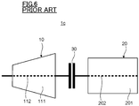
- a turbine power generation system with a single casing configuration is explained while using FIG. 6 .
- a turbine 10 is a single-flow type, and houses a turbine rotor 112 in a turbine casing 111.
- the power generator 20 includes the power generator rotor 202 connected to the turbine rotor 112 via the coupling 30.
- the power generator 20 is caused to generate power by rotation of the power generator rotor 202 caused by rotation of the turbine rotor 112.
- the turbine power generation system 1c with a single casing configuration has an overall length in the axial direction shorter than the turbine power generation systems 1a, 1b with a multiple casing configuration, thus making it easier to secure a place for installation, and due to a small number of parts, maintenance is easy.
- the load rejection is executed because of the occurrence of a problem in an electric power system (for example, the occurrence of an accident in a power transmission system because of thunderbolts).
- the power generator 20 is rapidly disconnected from the power transmission system and a control valve, or the like installed upstream of the turbine is rapidly closed, to thereby stop the supply of a working medium to the turbine 10.
- load rejection is to be performed, in the turbine 10, the energy remaining inside a pipe for supplying the working medium to the turbine casing 111 and the energy remaining inside the turbine casing 111 cause the turbine rotor 112 to rotate at an over-rotation speed exceeding its rated rotation speed.
- a large force is applied to rotary bodies such as the turbine rotor 112 and rotor blades supported by the turbine rotor 112, to increase the possibility of damage or the like.
- N maximum The over-rotation speed (N maximum) is calculated by using the following equation (A), for example.
- N maximum 7.3 ⁇ 105 / GD 2 ⁇ Er + ⁇ E 1 + ⁇ E 2 + ⁇ E 3
- the turbine power generation system 1c with a single casing configuration has a smaller number of turbine rotors 112 and has a shorter total length of the turbine rotor 112 as compared to the turbine power generation systems 1a, 1b with a multiple casing configuration (see FIG. 4 , FIG. 5 ), and thus, the entire weight of the turbine rotor 112 is lower. Therefore, the turbine power generation system 1c with a single casing configuration has a difficulty in inhibiting the over-rotation speed (N maximum) because of having a smaller moment of inertia as compared to the turbine power generation systems 1a, 1b with a multiple casing configuration. When the turbine power generation system 1c with a single casing configuration is increased in capacity, in particular, inhibiting the over-rotation speed (N maximum) is not easy.
- the turbine power generation system 1c with a single casing configuration had a difficulty in achieving a power generation output of 150 MW or more, to thus need to have a multiple casing configuration.
- a problem to be solved by the present invention is to provide a turbine power generation system with a single casing configuration capable of easily executing the inhibition of an over-rotation speed.
- a turbine power generation system in an embodiment includes: a turbine including a turbine casing and a turbine rotor that rotates by a working medium to be introduced into the turbine casing; and a power generator including a power generator rotor connected to the turbine rotor, the power generator being caused to generate power by rotation of the power generator rotor caused by the rotation of the turbine rotor.
- the turbine includes the turbine casing that is single, and a moment of inertia of the power generator rotor is larger than a moment of inertia of the turbine rotor.
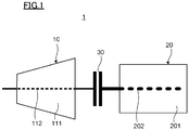
- the turbine power generation system according to the embodiment is explained while using FIG. 1 .
- a turbine power generation system 1 in this embodiment has a single casing configuration similarly to the above-described turbine power generation system 1c (see FIG. 6 ).
- a turbine 10 is a single-flow type, and houses a turbine rotor 112 in a turbine casing 111.
- a power generator 20 includes a power generator rotor 202 connected to the turbine rotor 112 via a coupling 30 and is caused to generate power by rotation of the power generator rotor 202 caused by rotation of the turbine rotor 112.
- the turbine power generation system 1 in this embodiment has the single turbine casing 111 and has a power generation capacity of 150 MW or more. Further, the turbine power generation system 1 is configured to make the moment of inertia of the power generator rotor 202 larger than that of the turbine rotor 112. For example, the outside diameter of the power generator rotor 202 is larger than that of the turbine rotor 112.
- Equation (i) represents the relationship between an annular area S of an annular turbine flow path through which the working medium passes inside the turbine 10, an average diameter PCD of the turbine flow path, and a height H of turbine blades (rotor blade • stator blade).
- S ⁇ ⁇ PCD ⁇ H
- the average diameter PCD of the turbine flow path is represented by a diameter D of the turbine rotor 112 (path inside diameter) and the height H of the turbine blades (rotor blade • stator blade) as represented in the following equation (ii).
- PCD D + H
- the diameter D of the turbine rotor 112 In order to increase the moment of inertia of the turbine rotor 112, the diameter D of the turbine rotor 112 needs to be increased. However, as is clear from the equation (i) and the equation (ii), in the case of the same annular area S, as the diameter D of the turbine rotor 112 is increased, the height H of the turbine blades (rotor blade • stator blade) is reduced. The performance of the turbine 10 decreases as the height H of the turbine blades (rotor blade • stator blade) is reduced. Therefore, it is difficult to arbitrarily increase the diameter D of the turbine rotor 112 in order to maintain the performance of the turbine 10, and it is not easy to increase the moment of inertia of the turbine rotor 112.
- the moment of inertia of the power generator rotor 202 is larger than that of the turbine rotor 112.
- the turbine power generation system 1 having the single turbine casing 111 and a large power generation capacity in this embodiment is capable of maintaining the performance of the turbine 10, and at the same time, effectively inhibiting the turbine rotor 112 from rotating at an over-rotation speed when load rejection is to be performed.
- the turbine power generation system 1c with a single casing configuration had a difficulty in achieving a power generation output of 150 MW or more, and was configured to have a multiple casing, to thereby achieve the power generation output of 150 MW or more.
- this embodiment can achieve both the performance of the turbine 10 and the inhibition of the turbine rotor 112 from overspeeding when load rejection is to be performed, and thus it is possible to achieve the power generation capacity of 150 MW or more in the turbine power generation system 1 with a single casing configuration.
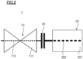
- the turbine 10 may be a double-flow type other than the single-flow type (see FIG. 1 ).
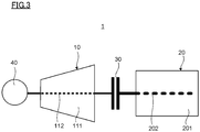
- the turbine power generation system 1 in this embodiment may include a pressure booster part 40 such as a compressor or a pump.
- the pressure booster part 40 is installed, for example, on the other end side of the turbine rotor 112 located opposite to one end side located on the power generator rotor 202 side, and a rotary shaft (whose illustration is omitted) of the pressure booster part 40 is connected to the turbine rotor 112.
Landscapes
- Engineering & Computer Science (AREA)
- Mechanical Engineering (AREA)
- General Engineering & Computer Science (AREA)
- Connection Of Motors, Electrical Generators, Mechanical Devices, And The Like (AREA)
Applications Claiming Priority (1)
| Application Number | Priority Date | Filing Date | Title |
|---|---|---|---|
| JP2020119048A JP2022015892A (ja) | 2020-07-10 | 2020-07-10 | タービン発電システム |
Publications (1)
| Publication Number | Publication Date |
|---|---|
| EP3936701A1 true EP3936701A1 (de) | 2022-01-12 |
Family
ID=76374994
Family Applications (1)
| Application Number | Title | Priority Date | Filing Date |
|---|---|---|---|
| EP21178761.9A Withdrawn EP3936701A1 (de) | 2020-07-10 | 2021-06-10 | Turbinenkraftwerkskonzept |
Country Status (3)
| Country | Link |
|---|---|
| US (1) | US11753959B2 (de) |
| EP (1) | EP3936701A1 (de) |
| JP (1) | JP2022015892A (de) |
Citations (3)
| Publication number | Priority date | Publication date | Assignee | Title |
|---|---|---|---|---|
| US4387562A (en) * | 1980-08-08 | 1983-06-14 | Nippon Steel Corporation | System for generating power with top pressure of blast furnaces |
| EP2154336A1 (de) * | 2007-04-27 | 2010-02-17 | Weizhong Feng | Neuer dampfturbinengeneratorsatz |
| GB2483866A (en) * | 2010-09-21 | 2012-03-28 | Nexxtdrive Ltd | Electric generator apparatus for a fluid turbine arrangement |
Family Cites Families (14)
| Publication number | Priority date | Publication date | Assignee | Title |
|---|---|---|---|---|
| US3151841A (en) * | 1963-04-03 | 1964-10-06 | Chrysler Corp | Fixed nozzle support |
| JPS6066640A (ja) | 1983-09-22 | 1985-04-16 | Toshiba Corp | 発電設備 |
| JPS62254649A (ja) * | 1986-04-25 | 1987-11-06 | Isuzu Motors Ltd | タ−ボチヤ−ジヤ用発電機 |
| JPH081124B2 (ja) | 1987-02-27 | 1996-01-10 | 株式会社日立製作所 | タ−ビン先行非常制御方法 |
| JP3898785B2 (ja) * | 1996-09-24 | 2007-03-28 | 株式会社日立製作所 | 高低圧一体型蒸気タービン用動翼と高低圧一体型蒸気タービン及びコンバインド発電システム並びに複合発電プラント |
| JP2003322028A (ja) * | 2002-05-07 | 2003-11-14 | Nishishiba Electric Co Ltd | ガスタービン発電装置 |
| US8596075B2 (en) | 2009-02-26 | 2013-12-03 | Palmer Labs, Llc | System and method for high efficiency power generation using a carbon dioxide circulating working fluid |
| US8816521B2 (en) * | 2012-03-15 | 2014-08-26 | General Electric Company | System for stabilizing power output by low-inertia turbine generator |
| CN104487678B (zh) * | 2012-08-03 | 2017-06-06 | 株式会社日立制作所 | 双轴式燃气轮机发电系统、燃气轮机系统的控制装置以及控制方法 |
| BR112015023395A8 (pt) | 2013-03-15 | 2019-12-03 | 8 Rivers Capital Llc | sistema e método para geração de energia de alta eficiência utilizando um fluido de trabalho circulante de dióxido de carbono |
| US9938853B2 (en) * | 2015-10-23 | 2018-04-10 | General Electric Company | Torsional damping for gas turbine engines |
| US20170298826A1 (en) * | 2016-04-18 | 2017-10-19 | John E. Ryznic | Industrial gas turbine engine with turbine airfoil cooling |
| US20190017443A1 (en) * | 2016-08-02 | 2019-01-17 | Rolls-Royce North American Technologies, Inc. | Rapidly available electric power from a turbine-generator system having an auxiliary power source |
| DE102018208087A1 (de) * | 2018-05-23 | 2019-11-28 | Siemens Aktiengesellschaft | Dampfturbinenanordnung |
-
2020
- 2020-07-10 JP JP2020119048A patent/JP2022015892A/ja active Pending
-
2021
- 2021-06-04 US US17/339,017 patent/US11753959B2/en active Active
- 2021-06-10 EP EP21178761.9A patent/EP3936701A1/de not_active Withdrawn
Patent Citations (3)
| Publication number | Priority date | Publication date | Assignee | Title |
|---|---|---|---|---|
| US4387562A (en) * | 1980-08-08 | 1983-06-14 | Nippon Steel Corporation | System for generating power with top pressure of blast furnaces |
| EP2154336A1 (de) * | 2007-04-27 | 2010-02-17 | Weizhong Feng | Neuer dampfturbinengeneratorsatz |
| GB2483866A (en) * | 2010-09-21 | 2012-03-28 | Nexxtdrive Ltd | Electric generator apparatus for a fluid turbine arrangement |
Non-Patent Citations (1)
| Title |
|---|
| MITESHKUMAR POPAT ET AL: "Fault Ride-Through Capability of Cascaded Current-Source Converter-Based Offshore Wind Farm", IEEE TRANSACTIONS ON SUSTAINABLE ENERGY, IEEE, USA, vol. 4, no. 2, 1 April 2013 (2013-04-01), pages 314 - 323, XP011497605, ISSN: 1949-3029, DOI: 10.1109/TSTE.2012.2223246 * |
Also Published As
| Publication number | Publication date |
|---|---|
| US20220010686A1 (en) | 2022-01-13 |
| JP2022015892A (ja) | 2022-01-21 |
| US11753959B2 (en) | 2023-09-12 |
Similar Documents
| Publication | Publication Date | Title |
|---|---|---|
| JP5202597B2 (ja) | 軸流圧縮機,軸流圧縮機を備えたガスタービンシステム及び軸流圧縮機の改造方法 | |
| EP3492699A1 (de) | Flüssigkeitsrückführungsturbinensystem | |
| US10247450B2 (en) | Device and method for converting thermal energy | |
| CN113266466A (zh) | 双轴式燃气轮机 | |
| EP2428664B1 (de) | Innere Entlüftungsstruktur einer 2-Wellen-Gasturbine | |
| US11333043B2 (en) | Steam turbine plant | |
| EP3936701A1 (de) | Turbinenkraftwerkskonzept | |
| JP4163131B2 (ja) | 二軸式ガスタービン発電システム及びその停止方法 | |
| US10927756B2 (en) | Multi-stage radial turboexpander | |
| CN113544370A (zh) | 多级压缩机-膨胀机涡轮机构型 | |
| CN105386876A (zh) | 联合循环发电设备 | |
| JP3177767B2 (ja) | コンバインド発電プラントの起動/停止方法 | |
| EP3348798B1 (de) | Dampfturbinensystem und zugehöriges kraftwerk | |
| WO2021118398A1 (ru) | Турбодетандерная энергетическая установка | |
| JP7837417B2 (ja) | 再循環ラインからエネルギーを回収する遠心圧縮機 | |
| JP2013064371A (ja) | 2段タービンシステム及びその緊急停止時の運転方法 | |
| JP7825768B1 (ja) | ガスタービンの制御方法およびガスタービン | |
| WO2013184042A2 (ru) | Многоступенчатая турбомашина (варианты) | |
| JP2011202515A (ja) | ガスタービンシステム | |
| JP3909466B2 (ja) | 蒸気タービンの運転方法 | |
| RU2776401C1 (ru) | Конфигурация многоступенчатой турбомашины (компрессора-детандера) | |
| CN102287240B (zh) | 蒸汽原动机 | |
| JPH0658109A (ja) | 昇圧機一体型膨張タービン | |
| WO2009130798A1 (ja) | 原動機 | |
| Wittchow | 4 Steam turbines: 3 Fossil-fueled power plants |
Legal Events
| Date | Code | Title | Description |
|---|---|---|---|
| PUAI | Public reference made under article 153(3) epc to a published international application that has entered the european phase |
Free format text: ORIGINAL CODE: 0009012 |
|
| STAA | Information on the status of an ep patent application or granted ep patent |
Free format text: STATUS: REQUEST FOR EXAMINATION WAS MADE |
|
| 17P | Request for examination filed |
Effective date: 20210610 |
|
| AK | Designated contracting states |
Kind code of ref document: A1 Designated state(s): AL AT BE BG CH CY CZ DE DK EE ES FI FR GB GR HR HU IE IS IT LI LT LU LV MC MK MT NL NO PL PT RO RS SE SI SK SM TR |
|
| B565 | Issuance of search results under rule 164(2) epc |
Effective date: 20210907 |
|
| STAA | Information on the status of an ep patent application or granted ep patent |
Free format text: STATUS: EXAMINATION IS IN PROGRESS |
|
| 17Q | First examination report despatched |
Effective date: 20231106 |
|
| STAA | Information on the status of an ep patent application or granted ep patent |
Free format text: STATUS: THE APPLICATION IS DEEMED TO BE WITHDRAWN |
|
| 18D | Application deemed to be withdrawn |
Effective date: 20240307 |