EP3936323A1 - Compression apparatus and methods of making and using the same - Google Patents
Compression apparatus and methods of making and using the same Download PDFInfo
- Publication number
- EP3936323A1 EP3936323A1 EP21184469.1A EP21184469A EP3936323A1 EP 3936323 A1 EP3936323 A1 EP 3936323A1 EP 21184469 A EP21184469 A EP 21184469A EP 3936323 A1 EP3936323 A1 EP 3936323A1
- Authority
- EP
- European Patent Office
- Prior art keywords
- plate
- face
- compression apparatus
- compression
- combination
- Prior art date
- Legal status (The legal status is an assumption and is not a legal conclusion. Google has not performed a legal analysis and makes no representation as to the accuracy of the status listed.)
- Granted
Links
Images


Classifications
-
- B—PERFORMING OPERATIONS; TRANSPORTING
- B30—PRESSES
- B30B—PRESSES IN GENERAL
- B30B15/00—Details of, or accessories for, presses; Auxiliary measures in connection with pressing
- B30B15/06—Platens or press rams
- B30B15/062—Press plates
-
- B—PERFORMING OPERATIONS; TRANSPORTING
- B64—AIRCRAFT; AVIATION; COSMONAUTICS
- B64G—COSMONAUTICS; VEHICLES OR EQUIPMENT THEREFOR
- B64G1/00—Cosmonautic vehicles
- B64G1/22—Parts of, or equipment specially adapted for fitting in or to, cosmonautic vehicles
- B64G1/60—Crew or passenger accommodations
-
- B—PERFORMING OPERATIONS; TRANSPORTING
- B30—PRESSES
- B30B—PRESSES IN GENERAL
- B30B15/00—Details of, or accessories for, presses; Auxiliary measures in connection with pressing
- B30B15/34—Heating or cooling presses or parts thereof
-
- B—PERFORMING OPERATIONS; TRANSPORTING
- B30—PRESSES
- B30B—PRESSES IN GENERAL
- B30B9/00—Presses specially adapted for particular purposes
- B30B9/02—Presses specially adapted for particular purposes for squeezing-out liquid from liquid-containing material, e.g. juice from fruits, oil from oil-containing material
- B30B9/04—Presses specially adapted for particular purposes for squeezing-out liquid from liquid-containing material, e.g. juice from fruits, oil from oil-containing material using press rams
-
- B—PERFORMING OPERATIONS; TRANSPORTING
- B30—PRESSES
- B30B—PRESSES IN GENERAL
- B30B9/00—Presses specially adapted for particular purposes
- B30B9/30—Presses specially adapted for particular purposes for baling; Compression boxes therefor
- B30B9/3003—Details
- B30B9/3021—Press rams
Definitions
- Exemplary embodiments pertain to the art of waste material compression and, more particularly, a compression apparatus which is located aboard a spacecraft.
- Waste materials can include, for example, organic food materials, scrap plastics, and used clothing.
- the processing of said waste materials can include the use of a compression apparatus, or more particularly, a waste compactor. During compression within the apparatus, high temperatures and pressures are developed on internal compressive surfaces.
- a compression apparatus comprising: an outer shell; a first plate and second plate, wherein the first plate and the second plate are located within the outer shell, wherein a face of the first plate opposes a face of the second plate; and a compression mechanism which retractably moves the face of the second plate into contact with the face of the first plate; wherein the face of the first plate or the face of the second plate comprises a substrate layer, and a coating layer over the substrate layer, wherein the coating layer comprises a plasma-enhanced chemical vapor deposition material.
- Also disclosed is a method of fabricating the compression apparatus comprising: fabricating the outer shell; fabricating the compression mechanism; coating the substrate layer(s) with the coating layer(s) via plasma-enhanced chemical vapor deposition material to form the first plate and the second plate; and configuring, within the outer shell, the face of the first plate to oppose the face of the second plate, and the compression mechanism to be in mechanical communication with the second plate.
- Also disclosed is a method of compressing waste materials using the compression apparatus comprising: depositing waste materials within the outer shell and between the face of the first plate and the face of the second plate; and activating the compression mechanism which moves the face of the second plate toward the face of the first plate, compressing the waste materials; wherein a surface temperature at the face of the first plate, the face of the second plate, or a combination thereof, is about 205°C to about 345°C; wherein a surface pressure at the face of the first plate, the face of the second plate, or a combination thereof, is about 170 kilopascal to about 690 kilopascal; and wherein the face of the first plate, the face of the second plate, or a combination thereof, maintains a solid phase during compression of the waste materials.
- a compression apparatus 10 can be, for example, a waste compactor.
- the compression apparatus 10 can be located in a microgravity environment, located aboard a spacecraft, or a combination thereof.
- an outer shell 12 of the compression apparatus 10 can comprise stainless steel, nickel alloy, titanium alloy, or a combination thereof.
- An atmospheric pressure within the outer shell 12 can be about 1.75 kilopascal to about 100 kilopascal (about 0.25 pound per square inch to about 14.7 pounds per square inch).
- a first plate 14 and second plate 16 can be located within the outer shell 12.
- a face 18 of the first plate 14 can oppose a face 20 of the second plate 16.
- a surface temperature at the face 18 of the first plate 14, the face 20 of the second plate 16, or a combination thereof, can be about 205°C to about 345°C (about 400°F to about 650°F).
- a surface pressure at the face 18 of the first plate 14, the face 20 of the second plate 16, or a combination thereof can be about 170 kilopascal to about 690 kilopascal (about 25 pound per square inch to about 100 pounds per square inch), for example, about 240 kilopascal to about 380 kilopascal (about 35 pound per square inch to about 55 pounds per square inch), for example, about 276 kilopascal to about 345 kilopascal (about 40 pound per square inch to about 50 pounds per square inch).
- a compression mechanism 22 of the compression apparatus 10 can retractably move (in the X direction) the face 20 of the second plate 16 into contact with the face 18 of the first plate 14, thereby compressing waste material between the first plate 14 and the second plate 16.
- the compression mechanism 22 can be any mechanical means of compression, for example, a jackscrew in mechanical communication with the second plate 16.
- a jackscrew can be operated by, for example, turning a leadscrew.
- This improved coating resists phase change from solid to non-solid, or in other words, maintains a solid phase, even when under high surface temperatures and pressures within the waste compactor, and even when located in a microgravity environment.
- This improved coating can last, for example, greater than or equal to 5 years being used once per 12-hour cycle.
- the face 18 of the first plate 14 or the face 20 of the second plate 16 can comprise a substrate layer 24, and a coating layer 26 over the substrate layer.
- both the face 18 of the first plate 14 and the face 20 of the second plate 16 can comprise a substrate layer 24 and a coating layer 26.
- the substrate layer 24 comprises stainless steel, nickel alloy, titanium alloy, or a combination thereof.
- the coating layer 26 can comprise a plasma-enhanced chemical vapor deposition material.
- Plasma-enhanced chemical vapor deposition is a chemical vapor deposition process used to deposit thin films from a gas state (vapor) to a solid state on a substrate. Chemical reactions are involved in the process, which occur after creation of a plasma of the reacting gases.
- the plasma can be created by radio frequency (RF), alternating current (AC) frequency, direct current (DC), or discharge between two electrodes, the space between which is filled with the reacting gases.
- the plasma-enhanced chemical vapor deposition material can comprise diamond-like carbon.
- Diamond-like carbon is a class of amorphous carbon material that displays properties of diamond.
- a thickness (in the X direction) of the coating layer 26 can be about 2.5 micrometer to about 50 micrometers.
- the coating layer 26 can be chemically inert to acids, bases, or a combination thereof.
- a contact angle of the coating layer 26 can be about 70 degrees to about 80 degrees. The contact angle is a measure of the wettability of a solid by a liquid. A high contact-angle values show the surface's tendency to repel a liquid.
- ISO 19403-2:2017 specifies a test method to measure the contact angle for the determination of the surface free energy of a solid surface. The method can be applied for the characterization of substrates and coatings.
- the ratio of hybridized sp 3 carbon to graphitic sp 2 carbon in the diamond-like carbon can be about 20:1 to about 3:1.
- a higher amount of hybridized sp 3 carbon can increase the density of the diamond-like carbon.
- the diamond-like carbon can further comprise a silicon additive.
- the coating layer 26 does not comprise polytetrafluoroethylene (Teflon).
- an intermediary layer 28 located between the substrate layer 24 and the coating layer 26.
- the intermediary layer 28 can comprise nitrides of chromium, aluminum, titanium, or any combinations thereof.
- a thickness (in the X direction) of the intermediary layer 28 can be about 0.1 micrometers to about 5 micrometers (about 3.9 microinches to about 196.9 microinches), for example, about 0.1 micrometers to about 2 micrometers (about 3.9 microinches to about 78.7 microinches).
- a method 30 of compressing waste materials using the compression apparatus 10 can comprise step 32: depositing waste materials within the outer shell 12 and between the face 18 of the first plate 14 and the face 20 of the second plate 16.
- the method 30 can further comprise step 34: activating the compression mechanism which moves the face 20 of the second plate 16 toward the face 18 of the first plate 14, compressing the waste materials.
- a surface temperature at the face 18 of the first plate 14, the face 20 of the second plate 16, or a combination thereof can be about 205°C to about 345°C (about 400°F to about 650°F).
- a surface pressure at the face 18 of the first plate 14, the face 20 of the second plate 16, or a combination thereof can be about 170 kilopascal to about 690 kilopascal (about 25 pound per square inch to about 100 pounds per square inch), for example, about 240 kilopascal to about 380 kilopascal (about 35 pound per square inch to about 55 pounds per square inch), for example, about 276 kilopascal to about 345 kilopascal (about 40 pound per square inch to about 50 pounds per square inch).
- the method 30 can further comprise step 36: the face 18 of the first plate 14, the face 20 of the second plate 16, or a combination thereof, maintains a solid phase during compression of the waste materials.
- method 40 of fabricating the compression apparatus 10 can comprise step 42: fabricating the outer shell 12.
- the method 40 can further comprise step 44: fabricating the compression mechanism.
- the method 40 can further comprise step 46: coating the substrate layer(s) with the coating layer(s) via plasma-enhanced chemical vapor deposition material to form the first plate and the second plate.
- the method 40 can further comprise step 48: configuring, within the outer shell, the face of the first plate to oppose the face of the second plate, and the compression mechanism to be in mechanical communication with the second plate.
Landscapes
- Engineering & Computer Science (AREA)
- Mechanical Engineering (AREA)
- Remote Sensing (AREA)
- Aviation & Aerospace Engineering (AREA)
- Chemical Vapour Deposition (AREA)
Abstract
Description
- Exemplary embodiments pertain to the art of waste material compression and, more particularly, a compression apparatus which is located aboard a spacecraft.
- Aircraft and/or spacecraft such as those used for the transport of passengers, for example, the International Space Station, process and dispose of waste materials produced by said passengers. Waste materials can include, for example, organic food materials, scrap plastics, and used clothing. The processing of said waste materials can include the use of a compression apparatus, or more particularly, a waste compactor. During compression within the apparatus, high temperatures and pressures are developed on internal compressive surfaces.
- Therefore, there is a need to develop an improved compression apparatus for use aboard a spacecraft and for the compression of waste material.
- Disclosed is a compression apparatus, comprising: an outer shell; a first plate and second plate, wherein the first plate and the second plate are located within the outer shell, wherein a face of the first plate opposes a face of the second plate; and a compression mechanism which retractably moves the face of the second plate into contact with the face of the first plate; wherein the face of the first plate or the face of the second plate comprises a substrate layer, and a coating layer over the substrate layer, wherein the coating layer comprises a plasma-enhanced chemical vapor deposition material.
- Also disclosed is a method of fabricating the compression apparatus, the method comprising: fabricating the outer shell; fabricating the compression mechanism; coating the substrate layer(s) with the coating layer(s) via plasma-enhanced chemical vapor deposition material to form the first plate and the second plate; and configuring, within the outer shell, the face of the first plate to oppose the face of the second plate, and the compression mechanism to be in mechanical communication with the second plate.
- Also disclosed is a method of compressing waste materials using the compression apparatus, the method comprising: depositing waste materials within the outer shell and between the face of the first plate and the face of the second plate; and activating the compression mechanism which moves the face of the second plate toward the face of the first plate, compressing the waste materials; wherein a surface temperature at the face of the first plate, the face of the second plate, or a combination thereof, is about 205°C to about 345°C; wherein a surface pressure at the face of the first plate, the face of the second plate, or a combination thereof, is about 170 kilopascal to about 690 kilopascal; and wherein the face of the first plate, the face of the second plate, or a combination thereof, maintains a solid phase during compression of the waste materials.
- The following descriptions should not be considered limiting in any way. With reference to the accompanying drawings, like elements are numbered alike:
-
FIG. 1 is a simplified schematic diagram of a compression apparatus according to an exemplary embodiment; -
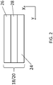
FIG. 2 is a cross-section of a face of a first plate according to an exemplary embodiment; -
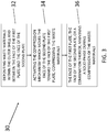
FIG. 3 is a flow diagram representing a method of compressing waste materials according to an exemplary embodiment; and -
FIG. 4 is a flow diagram representing a method of fabricating a compression apparatus according to an exemplary embodiment. - A detailed description of one or more embodiments of the disclosed coating and method are presented herein by way of exemplification and not limitation with reference to the Figures.
- Referring to
FIG. 1 , acompression apparatus 10 can be, for example, a waste compactor. Thecompression apparatus 10 can be located in a microgravity environment, located aboard a spacecraft, or a combination thereof. - In an embodiment, an
outer shell 12 of thecompression apparatus 10 can comprise stainless steel, nickel alloy, titanium alloy, or a combination thereof. An atmospheric pressure within theouter shell 12 can be about 1.75 kilopascal to about 100 kilopascal (about 0.25 pound per square inch to about 14.7 pounds per square inch). - In an embodiment, a
first plate 14 andsecond plate 16 can be located within theouter shell 12. Aface 18 of thefirst plate 14 can oppose aface 20 of thesecond plate 16. A surface temperature at theface 18 of thefirst plate 14, theface 20 of thesecond plate 16, or a combination thereof, can be about 205°C to about 345°C (about 400°F to about 650°F). A surface pressure at theface 18 of thefirst plate 14, theface 20 of thesecond plate 16, or a combination thereof, can be about 170 kilopascal to about 690 kilopascal (about 25 pound per square inch to about 100 pounds per square inch), for example, about 240 kilopascal to about 380 kilopascal (about 35 pound per square inch to about 55 pounds per square inch), for example, about 276 kilopascal to about 345 kilopascal (about 40 pound per square inch to about 50 pounds per square inch). - In an embodiment, a
compression mechanism 22 of thecompression apparatus 10 can retractably move (in the X direction) theface 20 of thesecond plate 16 into contact with theface 18 of thefirst plate 14, thereby compressing waste material between thefirst plate 14 and thesecond plate 16. Thecompression mechanism 22 can be any mechanical means of compression, for example, a jackscrew in mechanical communication with thesecond plate 16. A jackscrew can be operated by, for example, turning a leadscrew. - During compression within a waste material compression apparatus, high temperatures and pressures are developed on internal compressive surfaces. It has now been unexpectedly discovered that these internal surfaces, when coated with typical nickel or nickel-phosphorus plating with additional co-deposited, infused, or top coated polytetrafluoroethylene (Teflon), undergo a phase change from solid to non-solid. And as a result, the waste materials being compressed problematically adhere to these internal surfaces, thus necessitating expensive and time-consuming maintenance. The efficiency of the compactor is also reduced. The inventive solution disclosed herein includes the use of plasma-enhanced chemical vapor deposition material, for example diamond-like carbon, as a coating for the internal surfaces (i.e., the
face 18 and the face 20) of the compactor. This improved coating resists phase change from solid to non-solid, or in other words, maintains a solid phase, even when under high surface temperatures and pressures within the waste compactor, and even when located in a microgravity environment. This improved coating can last, for example, greater than or equal to 5 years being used once per 12-hour cycle. - Referring now to
FIG. 2 , theface 18 of thefirst plate 14 or theface 20 of thesecond plate 16 can comprise asubstrate layer 24, and acoating layer 26 over the substrate layer. In an embodiment, both theface 18 of thefirst plate 14 and theface 20 of thesecond plate 16 can comprise asubstrate layer 24 and acoating layer 26. - In an embodiment, the
substrate layer 24 comprises stainless steel, nickel alloy, titanium alloy, or a combination thereof. - In an embodiment, the
coating layer 26 can comprise a plasma-enhanced chemical vapor deposition material. Plasma-enhanced chemical vapor deposition is a chemical vapor deposition process used to deposit thin films from a gas state (vapor) to a solid state on a substrate. Chemical reactions are involved in the process, which occur after creation of a plasma of the reacting gases. The plasma can be created by radio frequency (RF), alternating current (AC) frequency, direct current (DC), or discharge between two electrodes, the space between which is filled with the reacting gases. - In an embodiment, the plasma-enhanced chemical vapor deposition material can comprise diamond-like carbon. Diamond-like carbon (DLC) is a class of amorphous carbon material that displays properties of diamond.
- In an embodiment, a thickness (in the X direction) of the
coating layer 26 can be about 2.5 micrometer to about 50 micrometers. Thecoating layer 26 can be chemically inert to acids, bases, or a combination thereof. A contact angle of thecoating layer 26 can be about 70 degrees to about 80 degrees. The contact angle is a measure of the wettability of a solid by a liquid. A high contact-angle values show the surface's tendency to repel a liquid. ISO 19403-2:2017 specifies a test method to measure the contact angle for the determination of the surface free energy of a solid surface. The method can be applied for the characterization of substrates and coatings. - In an embodiment, the ratio of hybridized sp3 carbon to graphitic sp2 carbon in the diamond-like carbon can be about 20:1 to about 3:1. A higher amount of hybridized sp3 carbon can increase the density of the diamond-like carbon. The diamond-like carbon can further comprise a silicon additive. In an embodiment, the
coating layer 26 does not comprise polytetrafluoroethylene (Teflon). - In an embodiment, there can further be an
intermediary layer 28 located between thesubstrate layer 24 and thecoating layer 26. Theintermediary layer 28 can comprise nitrides of chromium, aluminum, titanium, or any combinations thereof. A thickness (in the X direction) of theintermediary layer 28 can be about 0.1 micrometers to about 5 micrometers (about 3.9 microinches to about 196.9 microinches), for example, about 0.1 micrometers to about 2 micrometers (about 3.9 microinches to about 78.7 microinches). - Now referring to
FIG. 3 , amethod 30 of compressing waste materials using thecompression apparatus 10 can comprise step 32: depositing waste materials within theouter shell 12 and between theface 18 of thefirst plate 14 and theface 20 of thesecond plate 16. Themethod 30 can further comprise step 34: activating the compression mechanism which moves theface 20 of thesecond plate 16 toward theface 18 of thefirst plate 14, compressing the waste materials. - In an embodiment, a surface temperature at the
face 18 of thefirst plate 14, theface 20 of thesecond plate 16, or a combination thereof, can be about 205°C to about 345°C (about 400°F to about 650°F). - In an embodiment, a surface pressure at the
face 18 of thefirst plate 14, theface 20 of thesecond plate 16, or a combination thereof, can be about 170 kilopascal to about 690 kilopascal (about 25 pound per square inch to about 100 pounds per square inch), for example, about 240 kilopascal to about 380 kilopascal (about 35 pound per square inch to about 55 pounds per square inch), for example, about 276 kilopascal to about 345 kilopascal (about 40 pound per square inch to about 50 pounds per square inch). - The
method 30 can further comprise step 36: theface 18 of thefirst plate 14, theface 20 of thesecond plate 16, or a combination thereof, maintains a solid phase during compression of the waste materials. - Now referring to
FIG. 4 ,method 40 of fabricating thecompression apparatus 10 can comprise step 42: fabricating theouter shell 12. Themethod 40 can further comprise step 44: fabricating the compression mechanism. Themethod 40 can further comprise step 46: coating the substrate layer(s) with the coating layer(s) via plasma-enhanced chemical vapor deposition material to form the first plate and the second plate. Themethod 40 can further comprise step 48: configuring, within the outer shell, the face of the first plate to oppose the face of the second plate, and the compression mechanism to be in mechanical communication with the second plate. - The term "about" is intended to include the degree of error associated with measurement of the particular quantity based upon the equipment available at the time of filing the application.
- The terminology used herein is for the purpose of describing particular embodiments only and is not intended to be limiting of the present disclosure. As used herein, the singular forms "a", "an" and "the" are intended to include the plural forms as well, unless the context clearly indicates otherwise. It will be further understood that the terms "comprises" and/or "comprising," when used in this specification, specify the presence of stated features, integers, steps, operations, elements, and/or components (and encompasses "consist(s) of', "consisting of', "consist(s) essentially of' and "consisting essentially of'), but do not necessarily preclude the presence or addition of one or more other features, integers, steps, operations, element components, and/or groups thereof.
- While the present disclosure has been described with reference to an exemplary embodiment or embodiments, it will be understood by those skilled in the art that various changes may be made without departing from the scope of the invention as defined by the claims. In addition, many modifications may be made to adapt a particular situation or material to the teachings of the present disclosure without departing from the scope of the claims. Therefore, it is intended that the present disclosure not be limited to the particular embodiment disclosed as the best mode contemplated for carrying out this present disclosure, but that the present disclosure will include all embodiments falling within the scope of the claims.
Claims (15)
- A compression apparatus, comprising:an outer shell (12);a first plate (14) and second plate (16), wherein the first plate and the second plate are located within the outer shell, wherein a face (18) of the first plate opposes a face (20) of the second plate; anda compression mechanism (22) which retractably moves the face of the second plate into contact with the face of the first plate;wherein the face of the first plate or the face of the second plate comprises a substrate layer (24), and a coating layer (26) over the substrate layer, wherein the coating layer comprises a plasma-enhanced chemical vapor deposition material.
- The compression apparatus of Claim 1, wherein the outer shell (12) comprises stainless steel, nickel alloy, titanium alloy, or a combination thereof.
- The compression apparatus of Claim 1 or 2, wherein the compression mechanism (22) is a jackscrew in mechanical communication with the second plate.
- The compression apparatus of any preceding Claim, wherein both the face of the first plate and the face of the second plate comprise a substrate layer and a coating layer.
- The compression apparatus of any preceding Claim, wherein the substrate layer comprises stainless steel, titanium alloy, or a combination thereof.
- The compression apparatus of any preceding Claim, wherein the plasma-enhanced chemical vapor deposition material comprises diamond-like carbon, and optionally wherein the ratio of hybridized sp3 carbon to graphitic sp2 carbon in the diamond-like carbon is about 20:1 to about 3:1, or wherein the diamond-like carbon further comprises a silicon additive.
- The compression apparatus of any preceding Claim, wherein a thickness of the coating layer is about 2.5 micrometer to about 50 micrometers.
- The compression apparatus of any preceding Claim, wherein a surface temperature at the face of the first plate, the face of the second plate, or a combination thereof, is about 205°C to about 345°C, and/or wherein a surface pressure at the face of the first plate, the face of the second plate, or a combination thereof, is about 170 kilopascal to about 690 kilopascal.
- The compression apparatus of any preceding Claim, wherein the coating layer is chemically inert to acids, bases, or a combination thereof, and optionally wherein the coating layer does not comprise polytetrafluoroethylene.
- The compression apparatus of any preceding Claim, wherein a contact angle of the coating layer is about 70 degrees to about 80 degrees.
- The compression apparatus of any preceding Claim, wherein an atmospheric pressure within the outer shell is about 1.75 kilopascal to about 100 kilopascal.
- The compression apparatus of any preceding Claim, further comprising an intermediary layer (28) located between the substrate layer and the coating layer, wherein the intermediary layer comprises nitrides of chromium, aluminum, titanium, or any combinations thereof, and optionally wherein a thickness of the intermediary layer is about 0.1 micrometers to about 5 micrometers.
- The compression apparatus of any preceding Claim, wherein the compression apparatus is a waste compactor, wherein the compression apparatus is located in a microgravity environment, located aboard a spacecraft, or a combination thereof.
- A method of fabricating the compression apparatus of any preceding Claim, the method comprising:fabricating the outer shell (12);fabricating the compression mechanism (22);coating the substrate layer(s) (24) with the coating layer(s) (26) via plasma-enhanced chemical vapor deposition material to form the first plate (14) and the second plate (16); andconfiguring, within the outer shell, the face (18) of the first plate to oppose the face (20) of the second plate, and the compression mechanism to be in mechanical communication with the second plate.
- A method of compressing waste materials using the compression apparatus of any preceding Claim, the method comprising:depositing waste materials within the outer shell (12) and between the face (18) of the first plate (14) and the face (20) of the second plate (16); andactivating the compression mechanism (22) which moves the face of the second plate toward the face of the first plate, compressing the waste materials;wherein a surface temperature at the face of the first plate, the face of the second plate, or a combination thereof, is about 205°C to about 345°C;wherein a surface pressure at the face of the first plate, the face of the second plate, or a combination thereof, is about 170 kilopascal to about 690 kilopascal; andwherein the face of the first plate, the face of the second plate, or a combination thereof, maintains a solid phase during compression of the waste materials.
Applications Claiming Priority (1)
| Application Number | Priority Date | Filing Date | Title |
|---|---|---|---|
| US16/923,519 US11884426B2 (en) | 2020-07-08 | 2020-07-08 | Compression apparatus and methods of making and using the same |
Publications (2)
| Publication Number | Publication Date |
|---|---|
| EP3936323A1 true EP3936323A1 (en) | 2022-01-12 |
| EP3936323B1 EP3936323B1 (en) | 2024-01-10 |
Family
ID=77179850
Family Applications (1)
| Application Number | Title | Priority Date | Filing Date |
|---|---|---|---|
| EP21184469.1A Active EP3936323B1 (en) | 2020-07-08 | 2021-07-08 | Compression apparatus and methods of making and using the same |
Country Status (2)
| Country | Link |
|---|---|
| US (1) | US11884426B2 (en) |
| EP (1) | EP3936323B1 (en) |
Citations (7)
| Publication number | Priority date | Publication date | Assignee | Title |
|---|---|---|---|---|
| EP0847850A1 (en) * | 1996-12-13 | 1998-06-17 | Bayer Bitterfeld GmbH | Apparatus for pressing flowable solid materials or semi-solid materials |
| DE19810969A1 (en) * | 1998-03-13 | 1999-09-30 | Fraunhofer Ges Forschung | Flowable solids press tooling, especially punches for pressing powder to produce pharmaceutical tablets |
| DE102005009298A1 (en) * | 2005-03-01 | 2006-09-07 | Siempelkamp Maschinen- Und Anlagenbau Gmbh & Co. Kg | Continuous press producing chipboard or fibrous panels from mats, has components of spherical joint bearings coated with carbon-containing material, especially tungsten carbide |
| EP2233281A1 (en) * | 2009-03-26 | 2010-09-29 | Flooring Industries Limited, SARL | Method for manufacturing panels, floor panel obrained therewith and press platen applied therewith. |
| US9530624B2 (en) * | 2012-08-08 | 2016-12-27 | Berndorf Hueck Band- Und Pressblechtechnik Gmbh | Method for the plasma coating of a substrate, in particular a press platen |
| US20180318900A1 (en) * | 2015-12-01 | 2018-11-08 | Toyo Seikan Group Holdings, Ltd. | Mold and method for manufacturing drawn can |
| US20180354218A1 (en) * | 2017-06-09 | 2018-12-13 | Hamilton Sundstrand Corporation | Outer space waste compaction |
Family Cites Families (9)
| Publication number | Priority date | Publication date | Assignee | Title |
|---|---|---|---|---|
| KR100750582B1 (en) * | 2001-08-31 | 2007-08-21 | 기타가와 세이키 가부시키가이샤 | Method and apparatus for pressing a work piece |
| JP4704088B2 (en) * | 2005-03-31 | 2011-06-15 | 東京エレクトロン株式会社 | Plasma processing equipment |
| US20110089097A1 (en) * | 2009-10-19 | 2011-04-21 | O'reilly Dominick | Attachment and system for dewatering material |
| KR101954850B1 (en) * | 2011-03-09 | 2019-03-06 | 삼성전자주식회사 | Plasma generating system and plasma generating method |
| US8776680B2 (en) * | 2011-03-25 | 2014-07-15 | B/E Aerospace, Inc. | Modular apparatus and method for compacting trash |
| JP5931014B2 (en) * | 2013-07-12 | 2016-06-08 | 株式会社神戸製鋼所 | Hot isostatic press |
| CN107331604B (en) * | 2016-04-29 | 2020-06-16 | 上海微电子装备(集团)股份有限公司 | a bonding device |
| DE102016108362A1 (en) | 2016-05-04 | 2017-11-09 | Airbus Operations Gmbh | Trolley and system for collecting and compacting waste in a vehicle |
| US20180297310A1 (en) | 2017-04-13 | 2018-10-18 | Juicero, Inc. | Press |
-
2020
- 2020-07-08 US US16/923,519 patent/US11884426B2/en active Active
-
2021
- 2021-07-08 EP EP21184469.1A patent/EP3936323B1/en active Active
Patent Citations (7)
| Publication number | Priority date | Publication date | Assignee | Title |
|---|---|---|---|---|
| EP0847850A1 (en) * | 1996-12-13 | 1998-06-17 | Bayer Bitterfeld GmbH | Apparatus for pressing flowable solid materials or semi-solid materials |
| DE19810969A1 (en) * | 1998-03-13 | 1999-09-30 | Fraunhofer Ges Forschung | Flowable solids press tooling, especially punches for pressing powder to produce pharmaceutical tablets |
| DE102005009298A1 (en) * | 2005-03-01 | 2006-09-07 | Siempelkamp Maschinen- Und Anlagenbau Gmbh & Co. Kg | Continuous press producing chipboard or fibrous panels from mats, has components of spherical joint bearings coated with carbon-containing material, especially tungsten carbide |
| EP2233281A1 (en) * | 2009-03-26 | 2010-09-29 | Flooring Industries Limited, SARL | Method for manufacturing panels, floor panel obrained therewith and press platen applied therewith. |
| US9530624B2 (en) * | 2012-08-08 | 2016-12-27 | Berndorf Hueck Band- Und Pressblechtechnik Gmbh | Method for the plasma coating of a substrate, in particular a press platen |
| US20180318900A1 (en) * | 2015-12-01 | 2018-11-08 | Toyo Seikan Group Holdings, Ltd. | Mold and method for manufacturing drawn can |
| US20180354218A1 (en) * | 2017-06-09 | 2018-12-13 | Hamilton Sundstrand Corporation | Outer space waste compaction |
Also Published As
| Publication number | Publication date |
|---|---|
| EP3936323B1 (en) | 2024-01-10 |
| US11884426B2 (en) | 2024-01-30 |
| US20220009654A1 (en) | 2022-01-13 |
Similar Documents
| Publication | Publication Date | Title |
|---|---|---|
| Grischke et al. | Application-oriented modifications of deposition processes for diamond-like-carbon-based coatings | |
| US8701268B2 (en) | Composite showerhead electrode assembly for a plasma processing apparatus | |
| NO20160755A1 (en) | Apparatus for large scale producing 3D graphene and method describing the same | |
| JPS63153275A (en) | diamond coated alumina | |
| EP0561522A1 (en) | Method for electropolishing mandrels | |
| JPS62278264A (en) | Plasma support chemical vapor transport method for precipitating diamond like carbon film on support | |
| EP3936323B1 (en) | Compression apparatus and methods of making and using the same | |
| CN109161869A (en) | A method of corrosion-inhibiting coating is formed in metal part surface | |
| Michler et al. | Continuously deposited duplex coatings consisting of plasma nitriding and aC: H: Si deposition | |
| EP0528592A1 (en) | Method for selective CVD diamond deposition | |
| Michler et al. | Mechanical properties of DLC films prepared by bipolar pulsed DC PACVD | |
| JP2009525397A (en) | Thin film multilayer structure, component including the structure, and method for depositing the structure | |
| US20070148462A1 (en) | Article having diamond-like carbon composite film and method for manufacturing the same | |
| US7381452B2 (en) | Amorphous hydrogenated carbon film | |
| Dwivedi et al. | Unusual high hardness and load-dependent mechanical characteristics of hydrogenated carbon–nitrogen hybrid films | |
| JPH07256820A (en) | Slide member | |
| CN109267041A (en) | A kind of antistatic liquid-proof nano coating and preparation method thereof | |
| US20070004325A1 (en) | Method for manufacturing diamond film | |
| KR20150133720A (en) | Method for a diamond vapor deposition | |
| Freller et al. | Influence of intermediate layers and base materials on adhesion of amorphous carbon and metal-carbon coatings | |
| JPH03243770A (en) | Composite member and its production | |
| JP3748712B2 (en) | Resin molded body for liner | |
| CN115433901A (en) | antistatic coating | |
| JPH0361369A (en) | Manufacture of diamond like carbon film | |
| WO2008152666A1 (en) | Process for the deposition of layers of hydrogenated silicon carbide |
Legal Events
| Date | Code | Title | Description |
|---|---|---|---|
| PUAI | Public reference made under article 153(3) epc to a published international application that has entered the european phase |
Free format text: ORIGINAL CODE: 0009012 |
|
| STAA | Information on the status of an ep patent application or granted ep patent |
Free format text: STATUS: THE APPLICATION HAS BEEN PUBLISHED |
|
| AK | Designated contracting states |
Kind code of ref document: A1 Designated state(s): AL AT BE BG CH CY CZ DE DK EE ES FI FR GB GR HR HU IE IS IT LI LT LU LV MC MK MT NL NO PL PT RO RS SE SI SK SM TR |
|
| B565 | Issuance of search results under rule 164(2) epc |
Effective date: 20211119 |
|
| STAA | Information on the status of an ep patent application or granted ep patent |
Free format text: STATUS: REQUEST FOR EXAMINATION WAS MADE |
|
| 17P | Request for examination filed |
Effective date: 20220712 |
|
| RBV | Designated contracting states (corrected) |
Designated state(s): AL AT BE BG CH CY CZ DE DK EE ES FI FR GB GR HR HU IE IS IT LI LT LU LV MC MK MT NL NO PL PT RO RS SE SI SK SM TR |
|
| GRAP | Despatch of communication of intention to grant a patent |
Free format text: ORIGINAL CODE: EPIDOSNIGR1 |
|
| STAA | Information on the status of an ep patent application or granted ep patent |
Free format text: STATUS: GRANT OF PATENT IS INTENDED |
|
| RIC1 | Information provided on ipc code assigned before grant |
Ipc: B30B 15/34 20060101ALI20230719BHEP Ipc: B30B 15/06 20060101AFI20230719BHEP |
|
| INTG | Intention to grant announced |
Effective date: 20230816 |
|
| GRAS | Grant fee paid |
Free format text: ORIGINAL CODE: EPIDOSNIGR3 |
|
| GRAA | (expected) grant |
Free format text: ORIGINAL CODE: 0009210 |
|
| STAA | Information on the status of an ep patent application or granted ep patent |
Free format text: STATUS: THE PATENT HAS BEEN GRANTED |
|
| AK | Designated contracting states |
Kind code of ref document: B1 Designated state(s): AL AT BE BG CH CY CZ DE DK EE ES FI FR GB GR HR HU IE IS IT LI LT LU LV MC MK MT NL NO PL PT RO RS SE SI SK SM TR |
|
| REG | Reference to a national code |
Ref country code: GB Ref legal event code: FG4D |
|
| REG | Reference to a national code |
Ref country code: CH Ref legal event code: EP |
|
| REG | Reference to a national code |
Ref country code: DE Ref legal event code: R096 Ref document number: 602021008464 Country of ref document: DE |
|
| REG | Reference to a national code |
Ref country code: IE Ref legal event code: FG4D |
|
| REG | Reference to a national code |
Ref country code: LT Ref legal event code: MG9D |
|
| REG | Reference to a national code |
Ref country code: NL Ref legal event code: MP Effective date: 20240110 |
|
| REG | Reference to a national code |
Ref country code: AT Ref legal event code: MK05 Ref document number: 1648606 Country of ref document: AT Kind code of ref document: T Effective date: 20240110 |
|
| PG25 | Lapsed in a contracting state [announced via postgrant information from national office to epo] |
Ref country code: NL Free format text: LAPSE BECAUSE OF FAILURE TO SUBMIT A TRANSLATION OF THE DESCRIPTION OR TO PAY THE FEE WITHIN THE PRESCRIBED TIME-LIMIT Effective date: 20240110 |
|
| PG25 | Lapsed in a contracting state [announced via postgrant information from national office to epo] |
Ref country code: NL Free format text: LAPSE BECAUSE OF FAILURE TO SUBMIT A TRANSLATION OF THE DESCRIPTION OR TO PAY THE FEE WITHIN THE PRESCRIBED TIME-LIMIT Effective date: 20240110 |
|
| PG25 | Lapsed in a contracting state [announced via postgrant information from national office to epo] |
Ref country code: IS Free format text: LAPSE BECAUSE OF FAILURE TO SUBMIT A TRANSLATION OF THE DESCRIPTION OR TO PAY THE FEE WITHIN THE PRESCRIBED TIME-LIMIT Effective date: 20240510 |
|
| PG25 | Lapsed in a contracting state [announced via postgrant information from national office to epo] |
Ref country code: LT Free format text: LAPSE BECAUSE OF FAILURE TO SUBMIT A TRANSLATION OF THE DESCRIPTION OR TO PAY THE FEE WITHIN THE PRESCRIBED TIME-LIMIT Effective date: 20240110 |
|
| PG25 | Lapsed in a contracting state [announced via postgrant information from national office to epo] |
Ref country code: GR Free format text: LAPSE BECAUSE OF FAILURE TO SUBMIT A TRANSLATION OF THE DESCRIPTION OR TO PAY THE FEE WITHIN THE PRESCRIBED TIME-LIMIT Effective date: 20240411 |
|
| PG25 | Lapsed in a contracting state [announced via postgrant information from national office to epo] |
Ref country code: HR Free format text: LAPSE BECAUSE OF FAILURE TO SUBMIT A TRANSLATION OF THE DESCRIPTION OR TO PAY THE FEE WITHIN THE PRESCRIBED TIME-LIMIT Effective date: 20240110 Ref country code: RS Free format text: LAPSE BECAUSE OF FAILURE TO SUBMIT A TRANSLATION OF THE DESCRIPTION OR TO PAY THE FEE WITHIN THE PRESCRIBED TIME-LIMIT Effective date: 20240410 |
|
| PG25 | Lapsed in a contracting state [announced via postgrant information from national office to epo] |
Ref country code: ES Free format text: LAPSE BECAUSE OF FAILURE TO SUBMIT A TRANSLATION OF THE DESCRIPTION OR TO PAY THE FEE WITHIN THE PRESCRIBED TIME-LIMIT Effective date: 20240110 |
|
| PG25 | Lapsed in a contracting state [announced via postgrant information from national office to epo] |
Ref country code: AT Free format text: LAPSE BECAUSE OF FAILURE TO SUBMIT A TRANSLATION OF THE DESCRIPTION OR TO PAY THE FEE WITHIN THE PRESCRIBED TIME-LIMIT Effective date: 20240110 |
|
| PG25 | Lapsed in a contracting state [announced via postgrant information from national office to epo] |
Ref country code: RS Free format text: LAPSE BECAUSE OF FAILURE TO SUBMIT A TRANSLATION OF THE DESCRIPTION OR TO PAY THE FEE WITHIN THE PRESCRIBED TIME-LIMIT Effective date: 20240410 Ref country code: NO Free format text: LAPSE BECAUSE OF FAILURE TO SUBMIT A TRANSLATION OF THE DESCRIPTION OR TO PAY THE FEE WITHIN THE PRESCRIBED TIME-LIMIT Effective date: 20240410 Ref country code: LT Free format text: LAPSE BECAUSE OF FAILURE TO SUBMIT A TRANSLATION OF THE DESCRIPTION OR TO PAY THE FEE WITHIN THE PRESCRIBED TIME-LIMIT Effective date: 20240110 Ref country code: IS Free format text: LAPSE BECAUSE OF FAILURE TO SUBMIT A TRANSLATION OF THE DESCRIPTION OR TO PAY THE FEE WITHIN THE PRESCRIBED TIME-LIMIT Effective date: 20240510 Ref country code: HR Free format text: LAPSE BECAUSE OF FAILURE TO SUBMIT A TRANSLATION OF THE DESCRIPTION OR TO PAY THE FEE WITHIN THE PRESCRIBED TIME-LIMIT Effective date: 20240110 Ref country code: GR Free format text: LAPSE BECAUSE OF FAILURE TO SUBMIT A TRANSLATION OF THE DESCRIPTION OR TO PAY THE FEE WITHIN THE PRESCRIBED TIME-LIMIT Effective date: 20240411 Ref country code: ES Free format text: LAPSE BECAUSE OF FAILURE TO SUBMIT A TRANSLATION OF THE DESCRIPTION OR TO PAY THE FEE WITHIN THE PRESCRIBED TIME-LIMIT Effective date: 20240110 Ref country code: BG Free format text: LAPSE BECAUSE OF FAILURE TO SUBMIT A TRANSLATION OF THE DESCRIPTION OR TO PAY THE FEE WITHIN THE PRESCRIBED TIME-LIMIT Effective date: 20240110 Ref country code: AT Free format text: LAPSE BECAUSE OF FAILURE TO SUBMIT A TRANSLATION OF THE DESCRIPTION OR TO PAY THE FEE WITHIN THE PRESCRIBED TIME-LIMIT Effective date: 20240110 |
|
| PG25 | Lapsed in a contracting state [announced via postgrant information from national office to epo] |
Ref country code: PT Free format text: LAPSE BECAUSE OF FAILURE TO SUBMIT A TRANSLATION OF THE DESCRIPTION OR TO PAY THE FEE WITHIN THE PRESCRIBED TIME-LIMIT Effective date: 20240510 Ref country code: PL Free format text: LAPSE BECAUSE OF FAILURE TO SUBMIT A TRANSLATION OF THE DESCRIPTION OR TO PAY THE FEE WITHIN THE PRESCRIBED TIME-LIMIT Effective date: 20240110 |
|
| PG25 | Lapsed in a contracting state [announced via postgrant information from national office to epo] |
Ref country code: SE Free format text: LAPSE BECAUSE OF FAILURE TO SUBMIT A TRANSLATION OF THE DESCRIPTION OR TO PAY THE FEE WITHIN THE PRESCRIBED TIME-LIMIT Effective date: 20240110 Ref country code: PT Free format text: LAPSE BECAUSE OF FAILURE TO SUBMIT A TRANSLATION OF THE DESCRIPTION OR TO PAY THE FEE WITHIN THE PRESCRIBED TIME-LIMIT Effective date: 20240510 Ref country code: PL Free format text: LAPSE BECAUSE OF FAILURE TO SUBMIT A TRANSLATION OF THE DESCRIPTION OR TO PAY THE FEE WITHIN THE PRESCRIBED TIME-LIMIT Effective date: 20240110 Ref country code: LV Free format text: LAPSE BECAUSE OF FAILURE TO SUBMIT A TRANSLATION OF THE DESCRIPTION OR TO PAY THE FEE WITHIN THE PRESCRIBED TIME-LIMIT Effective date: 20240110 |
|
| PG25 | Lapsed in a contracting state [announced via postgrant information from national office to epo] |
Ref country code: DK Free format text: LAPSE BECAUSE OF FAILURE TO SUBMIT A TRANSLATION OF THE DESCRIPTION OR TO PAY THE FEE WITHIN THE PRESCRIBED TIME-LIMIT Effective date: 20240110 |
|
| REG | Reference to a national code |
Ref country code: DE Ref legal event code: R097 Ref document number: 602021008464 Country of ref document: DE |
|
| PG25 | Lapsed in a contracting state [announced via postgrant information from national office to epo] |
Ref country code: SM Free format text: LAPSE BECAUSE OF FAILURE TO SUBMIT A TRANSLATION OF THE DESCRIPTION OR TO PAY THE FEE WITHIN THE PRESCRIBED TIME-LIMIT Effective date: 20240110 |
|
| PG25 | Lapsed in a contracting state [announced via postgrant information from national office to epo] |
Ref country code: CZ Free format text: LAPSE BECAUSE OF FAILURE TO SUBMIT A TRANSLATION OF THE DESCRIPTION OR TO PAY THE FEE WITHIN THE PRESCRIBED TIME-LIMIT Effective date: 20240110 Ref country code: EE Free format text: LAPSE BECAUSE OF FAILURE TO SUBMIT A TRANSLATION OF THE DESCRIPTION OR TO PAY THE FEE WITHIN THE PRESCRIBED TIME-LIMIT Effective date: 20240110 |
|
| PG25 | Lapsed in a contracting state [announced via postgrant information from national office to epo] |
Ref country code: SK Free format text: LAPSE BECAUSE OF FAILURE TO SUBMIT A TRANSLATION OF THE DESCRIPTION OR TO PAY THE FEE WITHIN THE PRESCRIBED TIME-LIMIT Effective date: 20240110 |
|
| PG25 | Lapsed in a contracting state [announced via postgrant information from national office to epo] |
Ref country code: SM Free format text: LAPSE BECAUSE OF FAILURE TO SUBMIT A TRANSLATION OF THE DESCRIPTION OR TO PAY THE FEE WITHIN THE PRESCRIBED TIME-LIMIT Effective date: 20240110 Ref country code: SK Free format text: LAPSE BECAUSE OF FAILURE TO SUBMIT A TRANSLATION OF THE DESCRIPTION OR TO PAY THE FEE WITHIN THE PRESCRIBED TIME-LIMIT Effective date: 20240110 Ref country code: RO Free format text: LAPSE BECAUSE OF FAILURE TO SUBMIT A TRANSLATION OF THE DESCRIPTION OR TO PAY THE FEE WITHIN THE PRESCRIBED TIME-LIMIT Effective date: 20240110 Ref country code: EE Free format text: LAPSE BECAUSE OF FAILURE TO SUBMIT A TRANSLATION OF THE DESCRIPTION OR TO PAY THE FEE WITHIN THE PRESCRIBED TIME-LIMIT Effective date: 20240110 Ref country code: DK Free format text: LAPSE BECAUSE OF FAILURE TO SUBMIT A TRANSLATION OF THE DESCRIPTION OR TO PAY THE FEE WITHIN THE PRESCRIBED TIME-LIMIT Effective date: 20240110 Ref country code: CZ Free format text: LAPSE BECAUSE OF FAILURE TO SUBMIT A TRANSLATION OF THE DESCRIPTION OR TO PAY THE FEE WITHIN THE PRESCRIBED TIME-LIMIT Effective date: 20240110 |
|
| PLBE | No opposition filed within time limit |
Free format text: ORIGINAL CODE: 0009261 |
|
| STAA | Information on the status of an ep patent application or granted ep patent |
Free format text: STATUS: NO OPPOSITION FILED WITHIN TIME LIMIT |
|
| PG25 | Lapsed in a contracting state [announced via postgrant information from national office to epo] |
Ref country code: IT Free format text: LAPSE BECAUSE OF FAILURE TO SUBMIT A TRANSLATION OF THE DESCRIPTION OR TO PAY THE FEE WITHIN THE PRESCRIBED TIME-LIMIT Effective date: 20240110 |
|
| 26N | No opposition filed |
Effective date: 20241011 |
|
| PG25 | Lapsed in a contracting state [announced via postgrant information from national office to epo] |
Ref country code: IT Free format text: LAPSE BECAUSE OF FAILURE TO SUBMIT A TRANSLATION OF THE DESCRIPTION OR TO PAY THE FEE WITHIN THE PRESCRIBED TIME-LIMIT Effective date: 20240110 |
|
| PG25 | Lapsed in a contracting state [announced via postgrant information from national office to epo] |
Ref country code: MC Free format text: LAPSE BECAUSE OF FAILURE TO SUBMIT A TRANSLATION OF THE DESCRIPTION OR TO PAY THE FEE WITHIN THE PRESCRIBED TIME-LIMIT Effective date: 20240110 |
|
| REG | Reference to a national code |
Ref country code: CH Ref legal event code: PL |
|
| PG25 | Lapsed in a contracting state [announced via postgrant information from national office to epo] |
Ref country code: LU Free format text: LAPSE BECAUSE OF NON-PAYMENT OF DUE FEES Effective date: 20240708 |
|
| PG25 | Lapsed in a contracting state [announced via postgrant information from national office to epo] |
Ref country code: LU Free format text: LAPSE BECAUSE OF NON-PAYMENT OF DUE FEES Effective date: 20240708 |
|
| PG25 | Lapsed in a contracting state [announced via postgrant information from national office to epo] |
Ref country code: CH Free format text: LAPSE BECAUSE OF NON-PAYMENT OF DUE FEES Effective date: 20240731 Ref country code: SI Free format text: LAPSE BECAUSE OF FAILURE TO SUBMIT A TRANSLATION OF THE DESCRIPTION OR TO PAY THE FEE WITHIN THE PRESCRIBED TIME-LIMIT Effective date: 20240110 Ref country code: BE Free format text: LAPSE BECAUSE OF NON-PAYMENT OF DUE FEES Effective date: 20240731 |
|
| REG | Reference to a national code |
Ref country code: BE Ref legal event code: MM Effective date: 20240731 |
|
| PGFP | Annual fee paid to national office [announced via postgrant information from national office to epo] |
Ref country code: GB Payment date: 20250619 Year of fee payment: 5 |
|
| PGFP | Annual fee paid to national office [announced via postgrant information from national office to epo] |
Ref country code: FR Payment date: 20250620 Year of fee payment: 5 |
|
| PG25 | Lapsed in a contracting state [announced via postgrant information from national office to epo] |
Ref country code: IE Free format text: LAPSE BECAUSE OF NON-PAYMENT OF DUE FEES Effective date: 20240708 |
|
| PG25 | Lapsed in a contracting state [announced via postgrant information from national office to epo] |
Ref country code: FI Free format text: LAPSE BECAUSE OF FAILURE TO SUBMIT A TRANSLATION OF THE DESCRIPTION OR TO PAY THE FEE WITHIN THE PRESCRIBED TIME-LIMIT Effective date: 20240110 |
|
| PGFP | Annual fee paid to national office [announced via postgrant information from national office to epo] |
Ref country code: DE Payment date: 20250620 Year of fee payment: 5 |
|
| PG25 | Lapsed in a contracting state [announced via postgrant information from national office to epo] |
Ref country code: CY Free format text: LAPSE BECAUSE OF FAILURE TO SUBMIT A TRANSLATION OF THE DESCRIPTION OR TO PAY THE FEE WITHIN THE PRESCRIBED TIME-LIMIT; INVALID AB INITIO Effective date: 20210708 |
|
| PG25 | Lapsed in a contracting state [announced via postgrant information from national office to epo] |
Ref country code: HU Free format text: LAPSE BECAUSE OF FAILURE TO SUBMIT A TRANSLATION OF THE DESCRIPTION OR TO PAY THE FEE WITHIN THE PRESCRIBED TIME-LIMIT; INVALID AB INITIO Effective date: 20210708 |