EP3936276A1 - Needle peening method - Google Patents
Needle peening method Download PDFInfo
- Publication number
- EP3936276A1 EP3936276A1 EP19918827.7A EP19918827A EP3936276A1 EP 3936276 A1 EP3936276 A1 EP 3936276A1 EP 19918827 A EP19918827 A EP 19918827A EP 3936276 A1 EP3936276 A1 EP 3936276A1
- Authority
- EP
- European Patent Office
- Prior art keywords
- peening
- pin
- needle
- weld toe
- pins
- Prior art date
- Legal status (The legal status is an assumption and is not a legal conclusion. Google has not performed a legal analysis and makes no representation as to the accuracy of the status listed.)
- Granted
Links
Images




Classifications
-
- B—PERFORMING OPERATIONS; TRANSPORTING
- B23—MACHINE TOOLS; METAL-WORKING NOT OTHERWISE PROVIDED FOR
- B23K—SOLDERING OR UNSOLDERING; WELDING; CLADDING OR PLATING BY SOLDERING OR WELDING; CUTTING BY APPLYING HEAT LOCALLY, e.g. FLAME CUTTING; WORKING BY LASER BEAM
- B23K31/00—Processes relevant to this subclass, specially adapted for particular articles or purposes, but not covered by any single one of main groups B23K1/00 - B23K28/00
-
- B—PERFORMING OPERATIONS; TRANSPORTING
- B23—MACHINE TOOLS; METAL-WORKING NOT OTHERWISE PROVIDED FOR
- B23K—SOLDERING OR UNSOLDERING; WELDING; CLADDING OR PLATING BY SOLDERING OR WELDING; CUTTING BY APPLYING HEAT LOCALLY, e.g. FLAME CUTTING; WORKING BY LASER BEAM
- B23K9/00—Arc welding or cutting
- B23K9/23—Arc welding or cutting taking account of the properties of the materials to be welded
-
- C—CHEMISTRY; METALLURGY
- C21—METALLURGY OF IRON
- C21D—MODIFYING THE PHYSICAL STRUCTURE OF FERROUS METALS; GENERAL DEVICES FOR HEAT TREATMENT OF FERROUS OR NON-FERROUS METALS OR ALLOYS; MAKING METAL MALLEABLE, e.g. BY DECARBURISATION OR TEMPERING
- C21D7/00—Modifying the physical properties of iron or steel by deformation
- C21D7/02—Modifying the physical properties of iron or steel by deformation by cold working
- C21D7/04—Modifying the physical properties of iron or steel by deformation by cold working of the surface
- C21D7/06—Modifying the physical properties of iron or steel by deformation by cold working of the surface by shot-peening or the like
-
- B—PERFORMING OPERATIONS; TRANSPORTING
- B23—MACHINE TOOLS; METAL-WORKING NOT OTHERWISE PROVIDED FOR
- B23K—SOLDERING OR UNSOLDERING; WELDING; CLADDING OR PLATING BY SOLDERING OR WELDING; CUTTING BY APPLYING HEAT LOCALLY, e.g. FLAME CUTTING; WORKING BY LASER BEAM
- B23K9/00—Arc welding or cutting
- B23K9/16—Arc welding or cutting making use of shielding gas
-
- B—PERFORMING OPERATIONS; TRANSPORTING
- B23—MACHINE TOOLS; METAL-WORKING NOT OTHERWISE PROVIDED FOR
- B23P—METAL-WORKING NOT OTHERWISE PROVIDED FOR; COMBINED OPERATIONS; UNIVERSAL MACHINE TOOLS
- B23P9/00—Treating or finishing surfaces mechanically, with or without calibrating, primarily to resist wear or impact, e.g. smoothing or roughening turbine blades or bearings; Features of such surfaces not otherwise provided for, their treatment being unspecified
- B23P9/04—Treating or finishing by hammering or applying repeated pressure
-
- C—CHEMISTRY; METALLURGY
- C21—METALLURGY OF IRON
- C21D—MODIFYING THE PHYSICAL STRUCTURE OF FERROUS METALS; GENERAL DEVICES FOR HEAT TREATMENT OF FERROUS OR NON-FERROUS METALS OR ALLOYS; MAKING METAL MALLEABLE, e.g. BY DECARBURISATION OR TEMPERING
- C21D9/00—Heat treatment, e.g. annealing, hardening, quenching or tempering, adapted for particular articles; Furnaces therefor
- C21D9/50—Heat treatment, e.g. annealing, hardening, quenching or tempering, adapted for particular articles; Furnaces therefor for welded joints
-
- B—PERFORMING OPERATIONS; TRANSPORTING
- B23—MACHINE TOOLS; METAL-WORKING NOT OTHERWISE PROVIDED FOR
- B23K—SOLDERING OR UNSOLDERING; WELDING; CLADDING OR PLATING BY SOLDERING OR WELDING; CUTTING BY APPLYING HEAT LOCALLY, e.g. FLAME CUTTING; WORKING BY LASER BEAM
- B23K2101/00—Articles made by soldering, welding or cutting
- B23K2101/18—Sheet panels
-
- C—CHEMISTRY; METALLURGY
- C21—METALLURGY OF IRON
- C21D—MODIFYING THE PHYSICAL STRUCTURE OF FERROUS METALS; GENERAL DEVICES FOR HEAT TREATMENT OF FERROUS OR NON-FERROUS METALS OR ALLOYS; MAKING METAL MALLEABLE, e.g. BY DECARBURISATION OR TEMPERING
- C21D9/00—Heat treatment, e.g. annealing, hardening, quenching or tempering, adapted for particular articles; Furnaces therefor
- C21D9/46—Heat treatment, e.g. annealing, hardening, quenching or tempering, adapted for particular articles; Furnaces therefor for sheet metals
Definitions
- the present invention relates to a needle-peening method, and specifically relates to a needle-peening method of peening a weld toe of a welded joint for welding sheet metal.
- a distal end radius of the hammer tip or a radius of curvature of a distal end of the peening pin is too large as compared with a radius of curvature of the weld toe (weld extra-banking toe), so that there has been the problem that overlapping defects are caused at the weld toe due to a plastic flow of a material to be peened, fatigue is caused from the overlapping defects at the weld toe as a starting point, and the fatigue properties are not sufficiently improved.
- Patent Literature 3 discloses a needle-peening method of using a pin having a distal end radius equal to or larger than 1.0 mm and equal to or smaller than 2.0 mm to prevent overlapping defects from being caused when a plastic flow of metal is caused by impact of the pin.
- Patent Literature 4 discloses a needle-peening method for preventing overlapping defects at the weld toe based on a relation between a shape of a welding metal part and a distal end radius of a vibration pin. Additionally, there is disclosed a method of grinding the weld toe by using a grinder as preprocessing.
- Patent Literature 5 discloses a method of performing peening processing by a plurality of fixed pins that are arranged at intervals to be parallel with each other and have a predetermined angle with respect to a welding direction so that bulging edges of peening marks formed by needle-peening overlap with each other.
- a driving force required for giving a pressure for applying plastic deformation is increased as the distal end radius of the peening pin is increased, so that, in a case of using a peening pin having a distal end radius equal to or larger than 1.0 mm for a high-strength material, it has been required to use an expensive large device of an air-driving type (Patent Literature 2), an ultrasonic type (Patent Literature 3, Patent Literature 5), or the like.
- Patent Literature 2 an air-driving type
- Patent Literature 3 Patent Literature 5
- an overlapping defect 49 may be caused at a peening mark end in the vicinity of the weld toe, which may become a starting point of fatigue in some cases. Specifically, when the weld toe is peened along the welding direction, the overlapping defect 49 at the peening mark end continuous to the welding direction is formed.
- the overlapping defect 49 is assumed to be a notch continuous to a direction orthogonal to a direction of repeated tensile stress of fatigue.
- a stress caused at a bottom part of the notch becomes higher than that of a notch continuous to another direction (for example, a direction parallel to a tensile stress direction), so that generation and development of a crack are accelerated.
- Patent Literature 5 for performing peening processing with a plurality of pins so that bulging edges of peening marks overlap with each other, and there has been the problem that development of a crack cannot be prevented against a stress perpendicular to the welding direction.
- the present invention has been made for solving the problem as described above, and aims at providing a needle-peening method that can relieve stress concentration on the weld toe, and can prevent overlapping defects from being caused.
- a needle-peening method of peening a weld toe of a welded joint for welding and joining two pieces of sheet metal by using a peening pin, wherein a radius of curvature of a cross section perpendicular to a welding direction at a distal end part of the peening pin is equal to or larger than 0.05 mm and smaller than 1.00 mm, and the method includes: vibrating one or a plurality of the peening pins in a center axis direction; rotating the one peening pin about a single rotation axis parallel to the center axis while the center axis of the one peening pin is offset from the rotation axis, when using the one peening pin; rotating the plurality of the peening pins about the rotation axis, when using the plurality of the peening pins; and moving the one or the plurality of the peening pins along the welding direction to peen the weld toe.
- the plurality of the peening pins are arranged in a radial direction centered on the rotation axis.
- the plurality of the peening pins are arranged in a circumferential direction centered on the rotation axis.
- overlapping defects can be prevented from being caused at a weld toe, a welding ripple at the weld toe can be flattened, and fatigue properties of a welded joint can be improved.
- a radius of curvature of a weld toe is small, that is, 1.0 mm or less, stress concentration is difficult to be sufficiently relieved due to a sharp shape thereof.
- a radius of curvature of a cross section perpendicular to a welding direction of a distal end part of the peening pin needs to be increased to some degree, for example, to be equal to or larger than the radius of curvature of the weld toe to relieve stress concentration by peening the weld toe with a peening pin.
- the present inventors have found out that the fatigue properties are deteriorated by a minute projection and depression, which is called a welding ripple, having a size equal to or smaller than 0.05 mm generated at the weld toe at the time of welding.
- a welding ripple having a size equal to or smaller than 0.05 mm generated at the weld toe at the time of welding.
- the present inventors have found that a high-strength material having a tensile strength of 780 MPa grade or more is largely influenced by lowering of fatigue strength due to stress concentration on the weld toe, so that an effect of improving the fatigue properties is increased by relieving the stress concentration.
- the inventors have earnestly examined a method for relieving the shape of the weld toe without causing overlapping defects for the weld toe having a radius of curvature equal to or smaller than 1.0 mm, and flattening the welding ripple at the weld toe in peening the weld toe by the peening pin.
- the inventors found that, by peening the weld toe along the welding direction while rotating the peening pin having a radius of curvature smaller than the radius of curvature of the weld toe about a rotation axis offset from a center axis of the peening pin, the welding ripple at the weld toe can be flattened while preventing both of overlapping defects at the weld toe and overlapping defects at the peening mark end from being caused, and fatigue properties and productivity can be sufficiently improved.
- the needle-peening method according to the present embodiment is performed, as illustrated in FIG. 1 by way of example, by peening a weld toe 19 of a weld bead 17 in a welded joint 11 for welding and joining two pieces of sheet metal 13 and 15 by using a peening pin 1, and peening the weld toe 19 by vibrating the one peening pin 1 in a center axis direction, and moving the peening pin 1 along a welding direction while rotating the peening pin 1 about a rotation axis that is parallel to and offset from the center axis.
- a radius of curvature of a cross section perpendicular to the welding direction is equal to or larger than 0.05 mm and smaller than 1.00 mm.
- the rotation axis is set to be offset from the center axis of the peening pin 1.
- a plastic deformation region in a thickness direction due to peening is a surface layer of about 0.05 mm of a processed portion of the welded joint 11. Due to this, a strain gradient in the thickness direction becomes large, a local large compressive residual stress is obtained on a surface of the processed portion, and the fatigue strength is improved. Additionally, the plastic deformation region in the thickness direction is shallow, that is, about 0.05 mm, so that warping of sheet caused by the needle-peening processing is prevented.
- a peening pin having a radius of curvature equal to or larger than 1.00 mm has been used, but in the peening pin 1 according to the present embodiment, the distal end part 1a thereof has a small radius of curvature equal to or larger than 0.05 mm and smaller than 1.00 mm. Due to this, a contact area with respect to the processed portion of the welded joint 11 becomes smaller, so that it is possible to reduce a peening load applied to the peening pin 1 for generating a pressure to cause plastic deformation of the surface layer of the welded joint 11. Due to this, a tool for performing peening process can be downsized as compared with a conventional air-type peening or ultrasonic-type peening, and workability and productivity can be improved.
- the peening process width can be widened by rotating the peening pin about the offset rotation axis, so that it is possible to implement construction of securely peening the weld toe even in a welded joint in which a weld bead has an unstable shape or a curved shape.
- a range of a portion that should be peened is at least about 0.5 mm toward a weld bead side and a base metal side from the weld toe as a center.
- the present invention it is possible to easily and remarkably improve the fatigue properties of the welded joint obtained by welding and joining high-strength materials.
- An effect obtained by the present invention can be sufficiently given to automotive parts that are required to reduce the thickness and improve the fatigue properties.
- peening is performed while rotating the one peening pin 1.
- a plurality of the peening pins 1 may be vibrated in the center axis direction, and the peening pins 1 may be moved along the welding direction while being rotated about one rotation axis parallel to the center axis to peen the weld toe 19 of the weld bead 17.
- FIG. 2 illustrates the three peening pins 1 arranged in a radial direction centered on the rotation axis
- FIG. 3 illustrates the three peening pins 1 arranged in a circumferential direction centered on the rotation axis
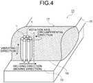
- FIG. 4 illustrates the peening pins 1 bundled at a position offset from the rotation axis.
- FIG. 5 illustrates a specific example of arrangement in a case in which the peening pins 1 are arranged in the radial direction centered on the rotation axis
- FIG. 6 illustrates a specific example of arrangement in a case in which the peening pins 1 are arranged in the circumferential direction centered on the rotation axis.
- the rotation axis is not required to be offset from center axes of all of the peening pins 1.
- the rotation axis may agree with the center axis of any one of the peening pins 1.
- the shape of the distal end part 1a of the peening pin 1 is not limited so long as the radius of curvature of the cross section perpendicular to the welding direction is equal to or larger than 0.05 mm and smaller than 1.00 mm.
- As the shape of the distal end part 1a for example, a hemispherical shape, a semi-elliptical shape, a semi-cylindrical shape, an abbreviated semi-cylindrical shape, and the like can be used.
- the welded joint 11 in the above description is a lap fillet welded joint obtained by lap fillet welding of the two pieces of sheet metal 13 and 15.
- the present invention is not only applied to the weld toe of the lap fillet welded joint, but also may be applied to a fillet welding joint such as a T-joint or a cruciform joint, a butt welding joint, and the like.
- a welding method for the welded joint is not limited to arc welding, and the present invention can be applied to a weld toe formed by any welding method.
- material of the sheet metal used as the base metal of the welded joint is not limited so long as the sheet metal is a thin plate.
- Two steel sheets 23 and 25 (300 ⁇ 140 mm) were cut out from a hot-rolled steel sheet having a thickness of 2.9 mm and a tensile strength of 980 MPa grade.
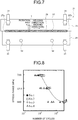
- the steel sheets 23 and 25 were fixed by a jig, and subjected to lap fillet arc welding to make a welded joint 21 (refer to FIG. 7 ).
- Welding conditions are indicated by Table 1.
- a radius of curvature of a weld toe 29 of the welded joint 21 was in a range from 0.2 mm to 0.8 mm.
- Table 1 Shielding gas Current (A) Voltage (V) Welding speed (cm/min) 80%Ar - 20%CO 2 230 23 80
- the needle-peening processing was performed by using a procedure described below.
- the welded joint 21 including positioning pin holes 33 was fixed by jigs 31.
- the peening pin 1 was vibrated by an electromagnetic tool disposed at a distal end of a robot arm (not illustrated), and the peening pin 1 was moved along a welding direction of the welded joint 21 while being rotated.
- the first welded joint 21 was subjected to the needle-peening processing. Subsequently, the first welded joint 21 was replaced with the welded joint 21 as the second one, and the needle-peening processing was performed under the conditions used for the teaching for the first welded joint 21. By repeating this work, five welded joints 21 in total were made with the same welding conditions and needle-peening conditions.
- the needle-peening processing was performed on the weld toe 29 of the made welded joint 21 by vibrating, by an electromagnetic tool at 100 Hz, the one peening pin 1 including the distal end part 1a in which the radius of curvature of the cross section perpendicular to the welding direction was 0.3 mm. Needle-peening processing conditions are indicated by Table 2. Table 2 No. Moving speed (cm/min) Radius of gyration (offset distance) (mm) Rotation speed (times/s) Remarks 1 80 2 7.5 Example 2 80 2 12 Example 3 80 1.5 12 Example 4 80 0 - Comparative example
- No. 1 to No. 3 are related to the needle-peening processing conditions according to the example of the present invention, and a moving speed, a radius of gyration (an offset distance between the center axis of the peening pin 1 and the rotation axis), and a rotation speed of the one peening pin 1 are changed.
- No. 4 indicates the needle-peening processing conditions for peening the weld toe without causing the one peening pin to be offset or rotated by comparison.
- FIG. 8 illustrates a fatigue test result.
- a horizontal axis indicates the number of cycles at which a repeated stress is loaded on the fatigue specimen to cause the fatigue crack (fatigue life)
- a vertical axis indicates a range of the stress to be loaded (a difference between a maximum stress and a minimum stress (0 MPa)).
- No. 4 according to a comparative example in which peening was performed without causing the peening pin to be offset or rotated obtained was a result in which variation in the fatigue life was huge.
- No. 1 to No. 3 according to the example of the present invention a favorable result was obtained such that substantially the same fatigue life was found in each stress range, and the fatigue life was longer than that of the comparative example in any stress range.
- the number of vibrations of the peening pin was 100 Hz
- the moving speed was 80 cm/min
- the radius of gyration an offset distance between the rotation axis and the center axis of the peening pin closest to the rotation axis
- the rotation speed was 7.5 times/s
- the radius of curvature of the cross section perpendicular to the welding direction at the distal end part of the peening pin was changed in a range from 0.03 mm to 1.00 mm.
- Table 3 indicates the radius of curvature of the distal end part of the peening pin, generation of the overlapping defect, wear of the distal end part of the peening pin, and an evaluation result obtained by integrating these items.
- Table 3 No. Radius of curvature of distal end part of peening pin (mm) Overlapping defect Wear of distal end part of peening pin Overall evaluation Remarks 11 0.03 Absent Much X Comparative example 12 0.05 Absent Little ⁇ Example 13 0.50 Absent Little ⁇ Example 14 0.80 Absent Little ⁇ Example 15 0.94 Absent Little ⁇ Example 16 1.00 Present Little X Comparative example
- the radius of curvature of the distal end part was 0.03 mm, and the overlapping defect was not caused at the weld toe.
- peening could not be sufficiently performed along the welding direction because wear of the distal end part was hard, so that the fatigue specimen to be used for the fatigue test could not be taken.
- the radius of curvature of the distal end part was 1.00 mm, which was larger than the radius of curvature of the weld toe, so that the overlapping defect was caused at the weld toe.
- FIG. 9 illustrates a result of the fatigue life of the fatigue specimen on which the needle-peening processing is performed by the peening pin including the distal end part having the radius of curvature indicated by Table 3.
- the needle-peening processing could not be continued because wear of the distal end part of the peening pin was hard, so that a required number of fatigue specimens for evaluation could not be taken.
- the radius of curvature of the distal end part was 1.00 mm, which was larger than a preferable range of the present invention, so that the overlapping defect was caused at the weld toe, and the fatigue crack was caused at the number of cycles of about 1 ⁇ 10 5 to 1.4 ⁇ 10 5 as indicated by Table 3 described above.
- the needle-peening processing was performed on the welded joint that was made under the welding conditions indicated by Table 1 while causing the radius of curvature of the distal end part of the peening pin to be 0.3 mm, and changing the arrangement of the peening pins, the number of the peening pins, and the radius of gyration.
- the plane bending fatigue test was then performed on the fatigue specimen after being processed under conditions of the repetition frequency of 15 Hz, the load stress of 650 MPa, and the stress ratio of 0 (pulsating) to evaluate the fatigue life.
- the number of vibrations of the peening pin was 100 Hz
- the moving speed was 80 cm/min
- the rotation speed was 7.5 times/s.
- the fatigue life was almost the same in No. 21 to No. 23 among which the radius of gyration was changed, the radius of gyration as the offset distance between the rotation axis and the center axis of the peening pin closest to the rotation center, and a favorable result was obtained under any condition.
- the present invention can provide a needle-peening method that can relieve stress concentration on a weld toe, and can prevent overlapping defects from being caused.
Landscapes
- Engineering & Computer Science (AREA)
- Chemical & Material Sciences (AREA)
- Mechanical Engineering (AREA)
- Materials Engineering (AREA)
- Crystallography & Structural Chemistry (AREA)
- Metallurgy (AREA)
- Organic Chemistry (AREA)
- Physics & Mathematics (AREA)
- Plasma & Fusion (AREA)
- Thermal Sciences (AREA)
- Butt Welding And Welding Of Specific Article (AREA)
- Infusion, Injection, And Reservoir Apparatuses (AREA)
Abstract
Description
- The present invention relates to a needle-peening method, and specifically relates to a needle-peening method of peening a weld toe of a welded joint for welding sheet metal.
- Typically, in most of automotive suspension parts, steel parts made of steel sheets are joined with each other by a welded joint. A load is repeatedly applied to the suspension part when an automobile is driving, so that fatigue may be caused in the suspension part. It is known that such fatigue tends to be caused at a weld, and most of the fatigue is a fracture mode caused by a crack parallel to a welding direction. The fracture mode is a fracture mode caused by a bending moment load in a direction parallel to the welding direction, that is, a stress perpendicular to the welding direction. Fatigue properties of the weld cannot be improved by high-strengthening of base metal, but is effectively compensated by increasing a thickness. Thus, the fatigue properties hinder reducing the wall thickness of the steel parts used for the suspension part. Accordingly, for the purpose of reducing the wall thickness, various techniques have been implemented for improving the fatigue properties of the weld.
- Most of the fatigue is caused at a weld toe of the weld, and it is known that a main cause of the fatigue is stress concentration on the weld toe and a tensile residual stress caused by welding. To solve this problem, as a method for relieving stress concentration by deforming the shape of the weld toe, and giving a compressive residual stress by plastic deformation at the same time, there has been implemented needle-peening processing of peening the weld toe by a vibrating hammer tip or peening pin (
Patent Literature 1 and Patent Literature 2). However, in the methods disclosed inPatent Literature 1 and Patent Literature 2, a distal end radius of the hammer tip or a radius of curvature of a distal end of the peening pin is too large as compared with a radius of curvature of the weld toe (weld extra-banking toe), so that there has been the problem that overlapping defects are caused at the weld toe due to a plastic flow of a material to be peened, fatigue is caused from the overlapping defects at the weld toe as a starting point, and the fatigue properties are not sufficiently improved. - Thus, Patent Literature 3 discloses a needle-peening method of using a pin having a distal end radius equal to or larger than 1.0 mm and equal to or smaller than 2.0 mm to prevent overlapping defects from being caused when a plastic flow of metal is caused by impact of the pin. Patent Literature 4 discloses a needle-peening method for preventing overlapping defects at the weld toe based on a relation between a shape of a welding metal part and a distal end radius of a vibration pin. Additionally, there is disclosed a method of grinding the weld toe by using a grinder as preprocessing.
- Furthermore, to further increase the compressive residual stress introduced by needle-peening, Patent Literature 5 discloses a method of performing peening processing by a plurality of fixed pins that are arranged at intervals to be parallel with each other and have a predetermined angle with respect to a welding direction so that bulging edges of peening marks formed by needle-peening overlap with each other.
-
- Patent Literature 1:
Japanese Patent No. 3002229 - Patent Literature 2:
Japanese Patent Application Laid-open No. 2014-008507 - Patent Literature 3:
Japanese Patent No. 4837428 - Patent Literature 4:
Japanese Patent Application Laid-open No. 2013-71140 - Patent Literature 5:
Japanese Patent Application Laid-open No. 2006-167724 - Most of automotive suspension parts are obtained by joining steel sheets having a thickness equal to or larger than 0.8 mm and equal to or smaller than 3.5 mm as base metal by a welded joint, and a radius of curvature of a weld toe of such a welded joint for steel sheets is about 0.2 mm to 1.0 mm. Thus, if the method disclosed in Patent Literature 3 is applied to the welded joint for the steel sheets, even when peening is performed by using a peening pin having a distal end radius of 1.0 mm, there has been the high risk that an
overlapping defect 47 is caused at the weld toe as illustrated inFIG. 10 . - In the method disclosed in Patent Literature 4, overlapping defects can be prevented from being caused based on a relational expression between the distal end radius of the peening pin (vibration pin) and a weld toe shape, but a flank angle of the welded joint is required to be equal to or smaller than 15 degrees, the welded joint in which the radius of curvature of the weld toe is 0.3 mm, for example. However, considering that a typical value of the flank angle is about 60 degrees, there has been the problem that the method disclosed in Patent Literature 4 cannot be applied to most welded joints made of steel sheets as base metal.
- A driving force required for giving a pressure for applying plastic deformation is increased as the distal end radius of the peening pin is increased, so that, in a case of using a peening pin having a distal end radius equal to or larger than 1.0 mm for a high-strength material, it has been required to use an expensive large device of an air-driving type (Patent Literature 2), an ultrasonic type (Patent Literature 3, Patent Literature 5), or the like. On the other hand, if the distal end radius of the peening pin is small, the overlapping
defect 47 at the weld toe as illustrated inFIG. 10 can be prevented from being caused, but an overlappingdefect 49 may be caused at a peening mark end in the vicinity of the weld toe, which may become a starting point of fatigue in some cases. Specifically, when the weld toe is peened along the welding direction, the overlappingdefect 49 at the peening mark end continuous to the welding direction is formed. - In a case in which a load is applied in a direction orthogonal to the overlapping
defect 49 at the peening mark end continuous to the welding direction, the overlappingdefect 49 is assumed to be a notch continuous to a direction orthogonal to a direction of repeated tensile stress of fatigue. In such a notch, a stress caused at a bottom part of the notch becomes higher than that of a notch continuous to another direction (for example, a direction parallel to a tensile stress direction), so that generation and development of a crack are accelerated. Due to this, there has been the problem that, when the load applied in the direction orthogonal to the welding direction is loaded onto the weld toe, if theoverlapping defect 49 at the peening mark end is formed in parallel to the welding direction, fatigue properties are prevented from being improved by peening with the peening pin. - Such a problem is also found in the method disclosed in Patent Literature 5 for performing peening processing with a plurality of pins so that bulging edges of peening marks overlap with each other, and there has been the problem that development of a crack cannot be prevented against a stress perpendicular to the welding direction.
- The present invention has been made for solving the problem as described above, and aims at providing a needle-peening method that can relieve stress concentration on the weld toe, and can prevent overlapping defects from being caused.
- To solve the problem and achieve the object, a needle-peening method according to the present invention of peening a weld toe of a welded joint for welding and joining two pieces of sheet metal by using a peening pin, wherein a radius of curvature of a cross section perpendicular to a welding direction at a distal end part of the peening pin is equal to or larger than 0.05 mm and smaller than 1.00 mm, and the method includes: vibrating one or a plurality of the peening pins in a center axis direction; rotating the one peening pin about a single rotation axis parallel to the center axis while the center axis of the one peening pin is offset from the rotation axis, when using the one peening pin; rotating the plurality of the peening pins about the rotation axis, when using the plurality of the peening pins; and moving the one or the plurality of the peening pins along the welding direction to peen the weld toe.
- Moreover, in the needle-peening method according to the present invention, the plurality of the peening pins are arranged in a radial direction centered on the rotation axis.
- Moreover, in the needle-peening method according to the present invention, the plurality of the peening pins are arranged in a circumferential direction centered on the rotation axis.
- According to the present invention, overlapping defects can be prevented from being caused at a weld toe, a welding ripple at the weld toe can be flattened, and fatigue properties of a welded joint can be improved. Brief Description of Drawings
-
FIG. 1 is a diagram for explaining a needle-peening method according to an embodiment of the present invention. -
FIG. 2 is a diagram for explaining another aspect of the needle-peening method according to the embodiment of the present invention (part 1). -
FIG. 3 is a diagram for explaining another aspect of the needle-peening method according to the embodiment of the present invention (part 2). -
FIG. 4 is a diagram for explaining another aspect of the needle-peening method according to the embodiment of the present invention (part 3). -
FIG. 5 is a diagram illustrating an example of arrangement of peening pins in the needle-peening method according to the embodiment of the present invention (part 1) . -
FIG. 6 is a diagram illustrating an example of arrangement of the peening pins in the needle-peening method according to the embodiment of the present invention (part 2) . -
FIG. 7 is a diagram for explaining processing using the needle-peening method according to the present invention in an example. -
FIG. 8 is a graph illustrating a fatigue test result in the example. -
FIG. 9 is a graph illustrating a relation between a radius of curvature of a distal end part of the peening pin and the number of cycles. -
FIG. 10 is a diagram for explaining a problem of a conventional needle-peening method. -
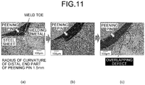
FIG. 11 is a diagram for explaining an overlapping defect caused by a conventional needle-peening method. Description of Embodiments - Conventionally, it has been considered that, in a case in which a radius of curvature of a weld toe is small, that is, 1.0 mm or less, stress concentration is difficult to be sufficiently relieved due to a sharp shape thereof. Thus, it has been considered that a radius of curvature of a cross section perpendicular to a welding direction of a distal end part of the peening pin needs to be increased to some degree, for example, to be equal to or larger than the radius of curvature of the weld toe to relieve stress concentration by peening the weld toe with a peening pin. However, there has been the risk that, if the weld toe is peened by a peening pin having a larger radius of curvature than that of the weld toe, an overlapping
defect 47 at the weld toe may be caused by a plastic flow of a material as illustrated inFIG. 10 andFIG. 11 . - On the other hand, if the weld toe is peened along the welding direction by using a peening pin having a smaller radius of curvature than the radius of curvature of the weld toe, as illustrated in
FIG. 10 , there has been a case in which overlappingdefects 49 at peening mark ends are continuously formed in the vicinity of the weld toe, and fatigue properties are deteriorated due to the overlappingdefects 49. - Thus, as a result of examining a cause of fatigue of the welded joint again in detail, the present inventors have found out that the fatigue properties are deteriorated by a minute projection and depression, which is called a welding ripple, having a size equal to or smaller than 0.05 mm generated at the weld toe at the time of welding. Specifically, the present inventors have found that a high-strength material having a tensile strength of 780 MPa grade or more is largely influenced by lowering of fatigue strength due to stress concentration on the weld toe, so that an effect of improving the fatigue properties is increased by relieving the stress concentration.
- Thus, the inventors have earnestly examined a method for relieving the shape of the weld toe without causing overlapping defects for the weld toe having a radius of curvature equal to or smaller than 1.0 mm, and flattening the welding ripple at the weld toe in peening the weld toe by the peening pin.
- As a result, the inventors found that, by peening the weld toe along the welding direction while rotating the peening pin having a radius of curvature smaller than the radius of curvature of the weld toe about a rotation axis offset from a center axis of the peening pin, the welding ripple at the weld toe can be flattened while preventing both of overlapping defects at the weld toe and overlapping defects at the peening mark end from being caused, and fatigue properties and productivity can be sufficiently improved.
- The following describes a needle-peening method according to an embodiment of the present invention based on
FIG. 1 to FIG. 6 by exemplifying a lap fillet welded joint. In the present application and the drawings, elements having substantially the same function or configuration are denoted by the same reference numeral, and redundant description will not be repeated. In the drawings used in the following description, a characteristic portion may be enlarged for convenience' sake to clarify the characteristic in some cases, but dimensions of or ratios between constituent elements are not necessarily the same as real dimensions or ratios. - The needle-peening method according to the present embodiment is performed, as illustrated in
FIG. 1 by way of example, by peening aweld toe 19 of aweld bead 17 in a welded joint 11 for welding and joining two pieces ofsheet metal peening pin 1, and peening theweld toe 19 by vibrating the onepeening pin 1 in a center axis direction, and moving thepeening pin 1 along a welding direction while rotating thepeening pin 1 about a rotation axis that is parallel to and offset from the center axis. - In the present embodiment, at a
distal end part 1a of thepeening pin 1, a radius of curvature of a cross section perpendicular to the welding direction is equal to or larger than 0.05 mm and smaller than 1.00 mm. By setting the radius of curvature of thedistal end part 1a in this range, a shape of minute projection and depression of theweld toe 19 can be relieved without being influenced by wear of thedistal end part 1a caused by peening, and overlapping defects can be prevented from being caused at theweld toe 19 by peening. - In a case of performing peening with the one
peening pin 1 as illustrated inFIG. 1 , the rotation axis is set to be offset from the center axis of thepeening pin 1. - In this way, by rotating the
peening pin 1 about the rotation axis offset from the center axis of thepeening pin 1, a peening process width is widened to peen and process the entire periphery of theweld toe 19, and the welding ripple at theweld toe 19 can be flattened. Due to this, preprocessing by a grinder and the like as disclosed in Patent Literature 4 is not required. - With the
peening pin 1 in which the radius of curvature of thedistal end part 1a is set to be in the range described above, a plastic deformation region in a thickness direction due to peening is a surface layer of about 0.05 mm of a processed portion of the welded joint 11. Due to this, a strain gradient in the thickness direction becomes large, a local large compressive residual stress is obtained on a surface of the processed portion, and the fatigue strength is improved. Additionally, the plastic deformation region in the thickness direction is shallow, that is, about 0.05 mm, so that warping of sheet caused by the needle-peening processing is prevented. - In the related art, a peening pin having a radius of curvature equal to or larger than 1.00 mm has been used, but in the
peening pin 1 according to the present embodiment, thedistal end part 1a thereof has a small radius of curvature equal to or larger than 0.05 mm and smaller than 1.00 mm. Due to this, a contact area with respect to the processed portion of the welded joint 11 becomes smaller, so that it is possible to reduce a peening load applied to thepeening pin 1 for generating a pressure to cause plastic deformation of the surface layer of the welded joint 11. Due to this, a tool for performing peening process can be downsized as compared with a conventional air-type peening or ultrasonic-type peening, and workability and productivity can be improved. - Furthermore, in the present invention, the peening process width can be widened by rotating the peening pin about the offset rotation axis, so that it is possible to implement construction of securely peening the weld toe even in a welded joint in which a weld bead has an unstable shape or a curved shape. In performing peening while rotating the peening pin, a range of a portion that should be peened is at least about 0.5 mm toward a weld bead side and a base metal side from the weld toe as a center.
- As a guideline for setting parameters, assuming that a frequency of peening pin vibration is fH [1/s], a rotation speed is f [1/s], and a radius of gyration (offset distance) is r [mm], the following relation may be satisfied.

- Assuming that a moving speed is v [mm/s], the following relation may be satisfied.

- As described above, according to the present invention, it is possible to easily and remarkably improve the fatigue properties of the welded joint obtained by welding and joining high-strength materials. An effect obtained by the present invention can be sufficiently given to automotive parts that are required to reduce the thickness and improve the fatigue properties.
- In the above description, peening is performed while rotating the one
peening pin 1. As other aspects of the present invention, as exemplified inFIG. 2 to FIG. 4 , a plurality of the peening pins 1 may be vibrated in the center axis direction, and the peening pins 1 may be moved along the welding direction while being rotated about one rotation axis parallel to the center axis to peen theweld toe 19 of theweld bead 17. -
FIG. 2 illustrates the threepeening pins 1 arranged in a radial direction centered on the rotation axis, andFIG. 3 illustrates the threepeening pins 1 arranged in a circumferential direction centered on the rotation axis.FIG. 4 illustrates the peening pins 1 bundled at a position offset from the rotation axis. -
FIG. 5 illustrates a specific example of arrangement in a case in which the peening pins 1 are arranged in the radial direction centered on the rotation axis, andFIG. 6 illustrates a specific example of arrangement in a case in which the peening pins 1 are arranged in the circumferential direction centered on the rotation axis. In a case of rotating the peening pins 1, as illustrated inFIG. 2 to FIG. 4 described above,FIG. 5(a), and FIG. 6(a) , the rotation axis is not required to be offset from center axes of all of the peening pins 1. As illustrated inFIGS. 5(b), (c), and FIG. 6(b) , the rotation axis may agree with the center axis of any one of the peening pins 1. - In this way, by arranging and rotating the peening pins 1 to perform peening, a peening area can be enlarged, and a peening speed can be increased without increasing the peening load applied to the peening pins 1. Additionally, as illustrated in
FIG. 4 , by rotating a bundle of the peening pins 1 at the same time, efficiency of peening can be further improved. - The shape of the
distal end part 1a of thepeening pin 1 is not limited so long as the radius of curvature of the cross section perpendicular to the welding direction is equal to or larger than 0.05 mm and smaller than 1.00 mm. As the shape of thedistal end part 1a, for example, a hemispherical shape, a semi-elliptical shape, a semi-cylindrical shape, an abbreviated semi-cylindrical shape, and the like can be used. - The welded joint 11 in the above description is a lap fillet welded joint obtained by lap fillet welding of the two pieces of
sheet metal - An experiment was performed to confirm a working effect of the present invention. The following describes the experiment. In this example, needle-peening processing was performed, by using a peening pin that performs peening while being rotated, on a weld toe of a weld bead in a welded joint obtained by lap fillet arc welding of two steel sheets. Subsequently, fatigue specimens were taken from the welded joint subjected to the needle-peening processing and the welded joint not subjected to the needle-peening processing by comparison, and a plane bending fatigue test was performed to evaluate a fatigue strength. Specific procedures and conditions are described below.
- Two
steel sheets 23 and 25 (300×140 mm) were cut out from a hot-rolled steel sheet having a thickness of 2.9 mm and a tensile strength of 980 MPa grade. Thesteel sheets FIG. 7 ). Welding conditions are indicated by Table 1. A radius of curvature of aweld toe 29 of the welded joint 21 was in a range from 0.2 mm to 0.8 mm.Table 1 Shielding gas Current (A) Voltage (V) Welding speed (cm/min) 80%Ar - 20%CO2 230 23 80 - In this example, the needle-peening processing was performed by using a procedure described below. First, as illustrated in
FIG. 7 , the welded joint 21 including positioning pin holes 33 was fixed byjigs 31. Thepeening pin 1 was vibrated by an electromagnetic tool disposed at a distal end of a robot arm (not illustrated), and thepeening pin 1 was moved along a welding direction of the welded joint 21 while being rotated. - In moving the
peening pin 1 by the robot arm, first, the welded joint 21 as the first one was used, and teaching was performed for the robot arm assuming that awelding start part 27a of aweld bead 27 was a peening process start position, and awelding end part 27b was a peening process end position. - Next, based on the teaching, the first welded joint 21 was subjected to the needle-peening processing. Subsequently, the first welded joint 21 was replaced with the welded joint 21 as the second one, and the needle-peening processing was performed under the conditions used for the teaching for the first welded joint 21. By repeating this work, five welded
joints 21 in total were made with the same welding conditions and needle-peening conditions. - In this way, four fatigue specimens were taken from each of the one welded joint 21 subjected to the needle-peening processing and the welded joint not subjected to the needle-peening processing by comparison, and a plane bending fatigue test was performed. Fatigue test conditions were set so that a repetition frequency was 15 Hz, and a stress ratio (a ratio between a minimum value and a maximum value of a stress loaded on the fatigue specimen) was 0 (pulsating). The number of cycles of loading the stress until a fatigue crack was caused in the fatigue specimen was measured, and the test was finished when the number of cycles reaches 3×10⁶, which was assumed to be a fatigue limit.
- The needle-peening processing was performed on the
weld toe 29 of the made welded joint 21 by vibrating, by an electromagnetic tool at 100 Hz, the onepeening pin 1 including thedistal end part 1a in which the radius of curvature of the cross section perpendicular to the welding direction was 0.3 mm. Needle-peening processing conditions are indicated by Table 2.Table 2 No. Moving speed (cm/min) Radius of gyration (offset distance) (mm) Rotation speed (times/s) Remarks 1 80 2 7.5 Example 2 80 2 12 Example 3 80 1.5 12 Example 4 80 0 - Comparative example - In Table 2, No. 1 to No. 3 are related to the needle-peening processing conditions according to the example of the present invention, and a moving speed, a radius of gyration (an offset distance between the center axis of the
peening pin 1 and the rotation axis), and a rotation speed of the onepeening pin 1 are changed. No. 4 indicates the needle-peening processing conditions for peening the weld toe without causing the one peening pin to be offset or rotated by comparison. -
FIG. 8 illustrates a fatigue test result. InFIG. 8 , a horizontal axis indicates the number of cycles at which a repeated stress is loaded on the fatigue specimen to cause the fatigue crack (fatigue life), and a vertical axis indicates a range of the stress to be loaded (a difference between a maximum stress and a minimum stress (0 MPa)). In No. 4 according to a comparative example in which peening was performed without causing the peening pin to be offset or rotated, obtained was a result in which variation in the fatigue life was huge. In contrast, in No. 1 to No. 3 according to the example of the present invention, a favorable result was obtained such that substantially the same fatigue life was found in each stress range, and the fatigue life was longer than that of the comparative example in any stress range. - Next, in the welded joint that was made under the welding conditions indicated by Table 1, the three peening pins illustrated in
FIG. 5(a) were arranged in the radial direction centered on the rotation axis, the radius of curvature of the distal end part of the peening pin was changed to perform the plane bending fatigue test for the fatigue specimen subjected to the needle-peening processing, and the fatigue life was evaluated. In the needle-peening processing, it was assumed that the number of vibrations of the peening pin was 100 Hz, the moving speed was 80 cm/min, the radius of gyration (an offset distance between the rotation axis and the center axis of the peening pin closest to the rotation axis) was 2 mm, and the rotation speed was 7.5 times/s, and the radius of curvature of the cross section perpendicular to the welding direction at the distal end part of the peening pin was changed in a range from 0.03 mm to 1.00 mm. - Assuming that the repetition frequency was 15 Hz, a load stress range was 650 MPa, and the stress ratio was 0 (pulsating), the number of cycles of loading the stress until the fatigue crack was caused in the fatigue specimen was measured, and the number of cycles of 3×10⁶ was assumed to be the fatigue limit. Additionally, the cross section perpendicular to the welding direction of the weld toe after being subjected to the needle-peening processing was photographed, and presence/absence of generation of an overlapping defect due to peening by the peening pin and wear of the distal end part of the peening pin due to peening were observed and evaluated. Table 3 indicates the radius of curvature of the distal end part of the peening pin, generation of the overlapping defect, wear of the distal end part of the peening pin, and an evaluation result obtained by integrating these items.
Table 3 No. Radius of curvature of distal end part of peening pin (mm) Overlapping defect Wear of distal end part of peening pin Overall evaluation Remarks 11 0.03 Absent Much X Comparative example 12 0.05 Absent Little ○ Example 13 0.50 Absent Little ○ Example 14 0.80 Absent Little ○ Example 15 0.94 Absent Little ○ Example 16 1.00 Present Little X Comparative example - According to Table 3, in No. 11 according to the comparative example, the radius of curvature of the distal end part was 0.03 mm, and the overlapping defect was not caused at the weld toe. However, peening could not be sufficiently performed along the welding direction because wear of the distal end part was hard, so that the fatigue specimen to be used for the fatigue test could not be taken.
- In No. 16 according to the comparative example, the radius of curvature of the distal end part was 1.00 mm, which was larger than the radius of curvature of the weld toe, so that the overlapping defect was caused at the weld toe.
- In contrast, in No. 12 to No. 15 in which the radius of curvature of the distal end part falls within the range of the present invention, the overlapping defect was not caused at the weld toe, and a degree of wear of the distal end part of the peening pin was sufficiently low and favorable.
-
FIG. 9 illustrates a result of the fatigue life of the fatigue specimen on which the needle-peening processing is performed by the peening pin including the distal end part having the radius of curvature indicated by Table 3. - As described above, in No. 11 of Table 3, the needle-peening processing could not be continued because wear of the distal end part of the peening pin was hard, so that a required number of fatigue specimens for evaluation could not be taken. In No. 16 according to the comparative example, the radius of curvature of the distal end part was 1.00 mm, which was larger than a preferable range of the present invention, so that the overlapping defect was caused at the weld toe, and the fatigue crack was caused at the number of cycles of about 1×10⁵ to 1.4×10⁵ as indicated by Table 3 described above.
- In contrast, in No. 12 to No. 15 according to the example of the present invention, a favorable result was obtained such that the fatigue life is the number of cycles of 2×10⁵ to 10×105 as compared with No. 16 according to the comparative example. A result was obtained such that, when the radius of curvature of the distal end part was increased in a range equal to or larger than 0.05 mm and smaller than 1.00 mm, the compressive residual stress working on a bottom of the peening mark formed by peening by the peening pin was increased, so that the fatigue life tended to be further improved.
- Furthermore, the needle-peening processing was performed on the welded joint that was made under the welding conditions indicated by Table 1 while causing the radius of curvature of the distal end part of the peening pin to be 0.3 mm, and changing the arrangement of the peening pins, the number of the peening pins, and the radius of gyration. The plane bending fatigue test was then performed on the fatigue specimen after being processed under conditions of the repetition frequency of 15 Hz, the load stress of 650 MPa, and the stress ratio of 0 (pulsating) to evaluate the fatigue life. In the needle-peening processing, it was assumed that the number of vibrations of the peening pin was 100 Hz, the moving speed was 80 cm/min, and the rotation speed was 7.5 times/s.
Table 4 No. Peening pin Result Remarks Arrangement Number Radius of gyration (mm) (offset distance to center axis of peening pin closest to rotation axis) Overlapping defect Fatigue life (average value of number of cycles) 21 Serial in radial direction of rotation axis 3 2 Absent 3.0 × 10⁵ Example FIG. 5(a) 22 Serial in radial direction of rotation axis 5 1 Absent 3.2 × 10⁵ Example FIG. 5(a) 23 Serial in radial direction of rotation axis 3 0 (center axis of peening pin at end part) Absent 2.8 × 10⁵ Example FIG. 5(b) 24 Serial in radial direction of rotation axis 3 0 (center axis of peening pin at center) Absent 2.5 × 10⁵ Example FIG. 5(c) 25 Circumferential direction of rotation axis 6 5 (all peening pins are on circumference) Absent 3.2 × 10⁵ Example FIG. 6(a) 26 Circumferential direction of rotation axis 6 5 (one peening pin agrees with rotation axis, and others are on circumference) Absent 3.0 × 10⁵ Example FIG. 6(b) - According to Table 4, the overlapping defect was not caused both in No. 21 to No. 24 in which the peening pins were arranged in the radial direction of the rotation axis, and in No. 25 and No. 26 in which the peening pins were arranged in the circumferential direction of the rotation axis. A favorable result of the fatigue life was obtained such that an average value of the number of cycles was high in all of No. 21 to No. 26 according to the example of the present invention as compared with the average value of the number of cycles of about 1.5×10⁵ in conventional No. 4 illustrated in
FIG. 8 in which the peening pins were not rotated. - The fatigue life was almost the same in No. 21 to No. 23 among which the radius of gyration was changed, the radius of gyration as the offset distance between the rotation axis and the center axis of the peening pin closest to the rotation center, and a favorable result was obtained under any condition.
- The present invention can provide a needle-peening method that can relieve stress concentration on a weld toe, and can prevent overlapping defects from being caused.
-
- 1
- PEENING PIN
- 1a
- DISTAL END PART
- 11
- WELDED JOINT
- 13, 15
- SHEET METAL
- 17
- WELD BEAD
- 19
- WELD TOE
- 21
- WELDED JOINT (EXAMPLE)
- 23, 25
- STEEL SHEET
- 27
- WELD BEAD
- 29
- WELD TOE
- 31
- JIG
- 33
- POSITIONING PIN HOLE
- 41
- PEENING PIN
- 43
- STEEL SHEET
- 45
- WELDING METAL
- 47
- OVERLAPPING DEFECT AT WELD TOE
- 49
- OVERLAPPING DEFECT AT PEENING MARK END
Claims (3)
- A needle-peening method of peening a weld toe of a welded joint for welding and joining two pieces of sheet metal by using a peening pin, whereina radius of curvature of a cross section perpendicular to a welding direction at a distal end part of the peening pin is equal to or larger than 0.05 mm and smaller than 1.00 mm, andthe method includes:vibrating one or a plurality of the peening pins in a center axis direction;rotating the one peening pin about a single rotation axis parallel to the center axis while the center axis of the one peening pin is offset from the rotation axis, when using the one peening pin;rotating the plurality of the peening pins about the rotation axis, when using the plurality of the peening pins; andmoving the one or the plurality of the peening pins along the welding direction to peen the weld toe.
- The needle-peening method according to claim 1, wherein the plurality of the peening pins are arranged in a radial direction centered on the rotation axis.
- The needle-peening method according to claim 1 or 2, wherein the plurality of the peening pins are arranged in a circumferential direction centered on the rotation axis.
Applications Claiming Priority (2)
| Application Number | Priority Date | Filing Date | Title |
|---|---|---|---|
| JP2019042366A JP6696604B1 (en) | 2019-03-08 | 2019-03-08 | Needle peening method |
| PCT/JP2019/043633 WO2020183783A1 (en) | 2019-03-08 | 2019-11-07 | Needle peening method |
Publications (3)
| Publication Number | Publication Date |
|---|---|
| EP3936276A1 true EP3936276A1 (en) | 2022-01-12 |
| EP3936276A4 EP3936276A4 (en) | 2022-04-20 |
| EP3936276B1 EP3936276B1 (en) | 2023-01-04 |
Family
ID=70682477
Family Applications (1)
| Application Number | Title | Priority Date | Filing Date |
|---|---|---|---|
| EP19918827.7A Active EP3936276B1 (en) | 2019-03-08 | 2019-11-07 | Needle peening method |
Country Status (7)
| Country | Link |
|---|---|
| US (2) | US12305246B2 (en) |
| EP (1) | EP3936276B1 (en) |
| JP (1) | JP6696604B1 (en) |
| KR (1) | KR102606405B1 (en) |
| CN (1) | CN113543927B (en) |
| MX (1) | MX2021010736A (en) |
| WO (1) | WO2020183783A1 (en) |
Families Citing this family (2)
| Publication number | Priority date | Publication date | Assignee | Title |
|---|---|---|---|---|
| JP7205601B1 (en) * | 2021-11-08 | 2023-01-17 | Jfeスチール株式会社 | METHOD FOR SUPPRESSING FATIGUE CRACK PROGRESSION OF BENDED METAL PLATE AND AUTOMOBILE PARTS |
| JP7251605B1 (en) * | 2021-12-17 | 2023-04-04 | Jfeスチール株式会社 | METHOD FOR SUPPRESSING FATIGUE CRACK PROGRESSION OF BENDED METAL PLATE AND AUTOMOBILE PARTS |
Family Cites Families (29)
| Publication number | Priority date | Publication date | Assignee | Title |
|---|---|---|---|---|
| US3600552A (en) | 1968-06-17 | 1971-08-17 | Sperry Rand Corp | Portable electric appliance |
| JPS5845782A (en) | 1982-08-05 | 1983-03-17 | 東亜燃料工業株式会社 | Washing of oil tank |
| JP3002229B2 (en) | 1990-05-14 | 2000-01-24 | 川崎製鉄株式会社 | Method for improving the fatigue strength of welded joints |
| JP2001179632A (en) * | 1999-12-28 | 2001-07-03 | Aisin Kiko Co Ltd | Peening device and method and machined product thereby |
| US6467321B2 (en) * | 2000-05-30 | 2002-10-22 | Integrity Testing Laboratory, Inc. | Device for ultrasonic peening of metals |
| JP4537649B2 (en) * | 2002-10-08 | 2010-09-01 | 新日本製鐵株式会社 | Rotating welded joint, manufacturing method of Rotated welded joint, and welded structure |
| JP4189201B2 (en) * | 2002-10-30 | 2008-12-03 | 新日本製鐵株式会社 | Method for improving toughness of heat-affected zone in steel welded joints |
| JP2004169103A (en) * | 2002-11-19 | 2004-06-17 | Nippon Steel Corp | Wire rod manufacturing method |
| JP4319830B2 (en) * | 2002-11-19 | 2009-08-26 | 新日本製鐵株式会社 | Ultrasonic shock treatment machine and ultrasonic shock treatment device |
| JP4392337B2 (en) | 2004-12-13 | 2009-12-24 | 新日本製鐵株式会社 | Processing method and structure using ultrasonic striking device |
| US7276824B2 (en) * | 2005-08-19 | 2007-10-02 | U.I.T., L.L.C. | Oscillating system and tool for ultrasonic impact treatment |
| JP4837428B2 (en) | 2006-04-17 | 2011-12-14 | 新日本製鐵株式会社 | Ultrasonic impact treatment method for weld toe |
| JP4709697B2 (en) * | 2006-06-23 | 2011-06-22 | 新日本製鐵株式会社 | Method for improving fatigue strength of metal lap weld joints |
| FR2920105B1 (en) | 2007-08-21 | 2010-02-05 | Saipem Sa | PROCESS FOR PROCESSING STEEL DRIVING WELDS INCLUDING THE DRYING OF WELDS WITHIN THE DRIVING |
| JP4987816B2 (en) * | 2008-07-28 | 2012-07-25 | 新日本製鐵株式会社 | Automatic impact processing method and automatic impact processing apparatus for improving the fatigue characteristics of welded joints |
| US8033151B2 (en) * | 2009-04-08 | 2011-10-11 | The Boeing Company | Method and apparatus for reducing force needed to form a shape from a sheet metal |
| JP4751484B1 (en) * | 2010-01-28 | 2011-08-17 | 新日本製鐵株式会社 | Fatigue property improving impact treatment apparatus for welded joint, fatigue property improving method, and method for manufacturing welded joint with improved fatigue property |
| JP5919986B2 (en) * | 2011-04-14 | 2016-05-18 | Jfeスチール株式会社 | Hammer peening treatment method and welded joint manufacturing method using the same |
| JP4952856B1 (en) * | 2011-07-19 | 2012-06-13 | Jfeエンジニアリング株式会社 | Hitting treatment method and apparatus |
| US9605328B2 (en) * | 2011-07-29 | 2017-03-28 | Progress Rail Services Corporation | Surface contouring of a weld cap and adjacent base metal using ultrasonic impact treatment |
| JP2013071140A (en) * | 2011-09-27 | 2013-04-22 | Nippon Steel & Sumitomo Metal Corp | Welded joint excellent in fatigue resistance and method for manufacturing the same |
| WO2013081015A1 (en) * | 2011-11-29 | 2013-06-06 | Jfeスチール株式会社 | Method for minimizing fatigue damage in welded structure, tool for forming strike mark, and welded structure |
| JP2014008507A (en) | 2012-06-27 | 2014-01-20 | Toyo Seiko Kk | Peening treatment method |
| JP6138450B2 (en) | 2012-10-10 | 2017-05-31 | 三菱重工業株式会社 | Peening apparatus and peening method |
| US10105815B2 (en) * | 2013-10-24 | 2018-10-23 | United Technologies Corporation | Multiaxial vibration-peening system |
| US10195655B2 (en) * | 2015-07-28 | 2019-02-05 | Ford Global Technologies, Llc | Vibration assisted free form fabrication |
| JP6756241B2 (en) * | 2015-11-13 | 2020-09-16 | 日本製鉄株式会社 | Ultrasonic impact treatment method |
| CN108239734A (en) * | 2016-12-26 | 2018-07-03 | 北京有色金属研究总院 | A kind of ultrasonic implement treatment method for reducing titanium-alloy thin-plate residual stress of welded structure |
| US11633811B2 (en) * | 2017-09-27 | 2023-04-25 | Jfe Steel Corporation | Method of peening lap fillet welded joint and welded structures |
-
2019
- 2019-03-08 JP JP2019042366A patent/JP6696604B1/en active Active
- 2019-11-07 US US17/436,272 patent/US12305246B2/en active Active
- 2019-11-07 MX MX2021010736A patent/MX2021010736A/en unknown
- 2019-11-07 EP EP19918827.7A patent/EP3936276B1/en active Active
- 2019-11-07 CN CN201980093752.8A patent/CN113543927B/en active Active
- 2019-11-07 KR KR1020217027115A patent/KR102606405B1/en active Active
- 2019-11-07 WO PCT/JP2019/043633 patent/WO2020183783A1/en not_active Ceased
-
2025
- 2025-03-14 US US19/079,943 patent/US20250207213A1/en active Pending
Also Published As
| Publication number | Publication date |
|---|---|
| JP2020142291A (en) | 2020-09-10 |
| WO2020183783A1 (en) | 2020-09-17 |
| KR102606405B1 (en) | 2023-11-24 |
| JP6696604B1 (en) | 2020-05-20 |
| CN113543927B (en) | 2022-11-22 |
| MX2021010736A (en) | 2021-12-10 |
| EP3936276A4 (en) | 2022-04-20 |
| US12305246B2 (en) | 2025-05-20 |
| US20250207213A1 (en) | 2025-06-26 |
| CN113543927A (en) | 2021-10-22 |
| US20220177988A1 (en) | 2022-06-09 |
| KR20210118159A (en) | 2021-09-29 |
| EP3936276B1 (en) | 2023-01-04 |
Similar Documents
| Publication | Publication Date | Title |
|---|---|---|
| US20250207213A1 (en) | Needle-peening method | |
| JP7099621B2 (en) | Double-sided friction stir welding method, cold-rolled steel strip and plated steel strip manufacturing method, double-sided friction stir welding equipment, and cold-rolled steel strip and plated steel strip manufacturing equipment | |
| EP3689531B1 (en) | Method of peening lap fillet welded joint and welded structures | |
| JP5720798B2 (en) | Method for suppressing fatigue crack growth of metal member and metal member with suppressed fatigue crack growth | |
| JP4895407B2 (en) | Peening method and welded joint using it | |
| CN100379883C (en) | Method for improving strength of cold-worked part by ultrasonic shock treatment and metal product | |
| JP6841042B2 (en) | Welded joint manufacturing method and welded joint | |
| Lefebvre et al. | Understanding of fatigue strength improvement of steel structures by hammer peening treatment | |
| JP2006320960A (en) | Metal parts or metal structures having excellent fatigue crack initiation / propagation suppression characteristics and methods for producing the same | |
| KR20240064740A (en) | Method for suppressing the propagation of fatigue cracks in bending processing parts of metal plates and automobile parts | |
| JP5919986B2 (en) | Hammer peening treatment method and welded joint manufacturing method using the same | |
| JP6828721B2 (en) | Peneening method and welded structure of lap fillet welded joint | |
| JP4854981B2 (en) | Friction welded parts with excellent fatigue resistance and methods for improving the fatigue characteristics | |
| JP6623926B2 (en) | Method of manufacturing welded structure and welded structure | |
| JP3802855B2 (en) | Method for improving fatigue strength of cut surface of high-tensile steel sheet and high-tensile steel sheet molded product using it | |
| JP4709697B2 (en) | Method for improving fatigue strength of metal lap weld joints | |
| EP4631670A1 (en) | Method of manufacturing metal sheet structure | |
| SU1118509A1 (en) | Method of straightening welded sheet constructions | |
| Marathe et al. | Study on Forming Behaviour of Friction Stir Welded Blanks During Single Point Incremental Forming (SPIF) Process | |
| JPS6297740A (en) | Manufacture of axle made of electric resistance welded steel pipe | |
| JP2018075633A (en) | Tool for forming striking trace and method for producing welded joint |
Legal Events
| Date | Code | Title | Description |
|---|---|---|---|
| STAA | Information on the status of an ep patent application or granted ep patent |
Free format text: STATUS: THE INTERNATIONAL PUBLICATION HAS BEEN MADE |
|
| PUAI | Public reference made under article 153(3) epc to a published international application that has entered the european phase |
Free format text: ORIGINAL CODE: 0009012 |
|
| STAA | Information on the status of an ep patent application or granted ep patent |
Free format text: STATUS: REQUEST FOR EXAMINATION WAS MADE |
|
| 17P | Request for examination filed |
Effective date: 20210823 |
|
| AK | Designated contracting states |
Kind code of ref document: A1 Designated state(s): AL AT BE BG CH CY CZ DE DK EE ES FI FR GB GR HR HU IE IS IT LI LT LU LV MC MK MT NL NO PL PT RO RS SE SI SK SM TR |
|
| A4 | Supplementary search report drawn up and despatched |
Effective date: 20220318 |
|
| RIC1 | Information provided on ipc code assigned before grant |
Ipc: B23K 9/16 20060101ALI20220314BHEP Ipc: B23K 9/23 20060101ALI20220314BHEP Ipc: C21D 9/50 20060101ALI20220314BHEP Ipc: C21D 9/46 20060101ALI20220314BHEP Ipc: C21D 7/06 20060101ALI20220314BHEP Ipc: B23P 9/04 20060101ALI20220314BHEP Ipc: B23K 31/00 20060101AFI20220314BHEP |
|
| DAV | Request for validation of the european patent (deleted) | ||
| DAX | Request for extension of the european patent (deleted) | ||
| GRAP | Despatch of communication of intention to grant a patent |
Free format text: ORIGINAL CODE: EPIDOSNIGR1 |
|
| STAA | Information on the status of an ep patent application or granted ep patent |
Free format text: STATUS: GRANT OF PATENT IS INTENDED |
|
| INTG | Intention to grant announced |
Effective date: 20220905 |
|
| GRAS | Grant fee paid |
Free format text: ORIGINAL CODE: EPIDOSNIGR3 |
|
| GRAA | (expected) grant |
Free format text: ORIGINAL CODE: 0009210 |
|
| STAA | Information on the status of an ep patent application or granted ep patent |
Free format text: STATUS: THE PATENT HAS BEEN GRANTED |
|
| AK | Designated contracting states |
Kind code of ref document: B1 Designated state(s): AL AT BE BG CH CY CZ DE DK EE ES FI FR GB GR HR HU IE IS IT LI LT LU LV MC MK MT NL NO PL PT RO RS SE SI SK SM TR |
|
| REG | Reference to a national code |
Ref country code: GB Ref legal event code: FG4D |
|
| REG | Reference to a national code |
Ref country code: CH Ref legal event code: EP |
|
| REG | Reference to a national code |
Ref country code: AT Ref legal event code: REF Ref document number: 1541586 Country of ref document: AT Kind code of ref document: T Effective date: 20230115 |
|
| REG | Reference to a national code |
Ref country code: DE Ref legal event code: R096 Ref document number: 602019024157 Country of ref document: DE |
|
| REG | Reference to a national code |
Ref country code: IE Ref legal event code: FG4D |
|
| REG | Reference to a national code |
Ref country code: LT Ref legal event code: MG9D |
|
| REG | Reference to a national code |
Ref country code: NL Ref legal event code: MP Effective date: 20230104 |
|
| REG | Reference to a national code |
Ref country code: AT Ref legal event code: MK05 Ref document number: 1541586 Country of ref document: AT Kind code of ref document: T Effective date: 20230104 |
|
| PG25 | Lapsed in a contracting state [announced via postgrant information from national office to epo] |
Ref country code: NL Free format text: LAPSE BECAUSE OF FAILURE TO SUBMIT A TRANSLATION OF THE DESCRIPTION OR TO PAY THE FEE WITHIN THE PRESCRIBED TIME-LIMIT Effective date: 20230104 |
|
| PG25 | Lapsed in a contracting state [announced via postgrant information from national office to epo] |
Ref country code: RS Free format text: LAPSE BECAUSE OF FAILURE TO SUBMIT A TRANSLATION OF THE DESCRIPTION OR TO PAY THE FEE WITHIN THE PRESCRIBED TIME-LIMIT Effective date: 20230104 Ref country code: PT Free format text: LAPSE BECAUSE OF FAILURE TO SUBMIT A TRANSLATION OF THE DESCRIPTION OR TO PAY THE FEE WITHIN THE PRESCRIBED TIME-LIMIT Effective date: 20230504 Ref country code: NO Free format text: LAPSE BECAUSE OF FAILURE TO SUBMIT A TRANSLATION OF THE DESCRIPTION OR TO PAY THE FEE WITHIN THE PRESCRIBED TIME-LIMIT Effective date: 20230404 Ref country code: LV Free format text: LAPSE BECAUSE OF FAILURE TO SUBMIT A TRANSLATION OF THE DESCRIPTION OR TO PAY THE FEE WITHIN THE PRESCRIBED TIME-LIMIT Effective date: 20230104 Ref country code: LT Free format text: LAPSE BECAUSE OF FAILURE TO SUBMIT A TRANSLATION OF THE DESCRIPTION OR TO PAY THE FEE WITHIN THE PRESCRIBED TIME-LIMIT Effective date: 20230104 Ref country code: HR Free format text: LAPSE BECAUSE OF FAILURE TO SUBMIT A TRANSLATION OF THE DESCRIPTION OR TO PAY THE FEE WITHIN THE PRESCRIBED TIME-LIMIT Effective date: 20230104 Ref country code: ES Free format text: LAPSE BECAUSE OF FAILURE TO SUBMIT A TRANSLATION OF THE DESCRIPTION OR TO PAY THE FEE WITHIN THE PRESCRIBED TIME-LIMIT Effective date: 20230104 Ref country code: AT Free format text: LAPSE BECAUSE OF FAILURE TO SUBMIT A TRANSLATION OF THE DESCRIPTION OR TO PAY THE FEE WITHIN THE PRESCRIBED TIME-LIMIT Effective date: 20230104 |
|
| PG25 | Lapsed in a contracting state [announced via postgrant information from national office to epo] |
Ref country code: SE Free format text: LAPSE BECAUSE OF FAILURE TO SUBMIT A TRANSLATION OF THE DESCRIPTION OR TO PAY THE FEE WITHIN THE PRESCRIBED TIME-LIMIT Effective date: 20230104 Ref country code: PL Free format text: LAPSE BECAUSE OF FAILURE TO SUBMIT A TRANSLATION OF THE DESCRIPTION OR TO PAY THE FEE WITHIN THE PRESCRIBED TIME-LIMIT Effective date: 20230104 Ref country code: IS Free format text: LAPSE BECAUSE OF FAILURE TO SUBMIT A TRANSLATION OF THE DESCRIPTION OR TO PAY THE FEE WITHIN THE PRESCRIBED TIME-LIMIT Effective date: 20230504 Ref country code: GR Free format text: LAPSE BECAUSE OF FAILURE TO SUBMIT A TRANSLATION OF THE DESCRIPTION OR TO PAY THE FEE WITHIN THE PRESCRIBED TIME-LIMIT Effective date: 20230405 Ref country code: FI Free format text: LAPSE BECAUSE OF FAILURE TO SUBMIT A TRANSLATION OF THE DESCRIPTION OR TO PAY THE FEE WITHIN THE PRESCRIBED TIME-LIMIT Effective date: 20230104 |
|
| REG | Reference to a national code |
Ref country code: DE Ref legal event code: R097 Ref document number: 602019024157 Country of ref document: DE |
|
| PG25 | Lapsed in a contracting state [announced via postgrant information from national office to epo] |
Ref country code: SM Free format text: LAPSE BECAUSE OF FAILURE TO SUBMIT A TRANSLATION OF THE DESCRIPTION OR TO PAY THE FEE WITHIN THE PRESCRIBED TIME-LIMIT Effective date: 20230104 Ref country code: RO Free format text: LAPSE BECAUSE OF FAILURE TO SUBMIT A TRANSLATION OF THE DESCRIPTION OR TO PAY THE FEE WITHIN THE PRESCRIBED TIME-LIMIT Effective date: 20230104 Ref country code: EE Free format text: LAPSE BECAUSE OF FAILURE TO SUBMIT A TRANSLATION OF THE DESCRIPTION OR TO PAY THE FEE WITHIN THE PRESCRIBED TIME-LIMIT Effective date: 20230104 Ref country code: DK Free format text: LAPSE BECAUSE OF FAILURE TO SUBMIT A TRANSLATION OF THE DESCRIPTION OR TO PAY THE FEE WITHIN THE PRESCRIBED TIME-LIMIT Effective date: 20230104 Ref country code: CZ Free format text: LAPSE BECAUSE OF FAILURE TO SUBMIT A TRANSLATION OF THE DESCRIPTION OR TO PAY THE FEE WITHIN THE PRESCRIBED TIME-LIMIT Effective date: 20230104 |
|
| PLBE | No opposition filed within time limit |
Free format text: ORIGINAL CODE: 0009261 |
|
| STAA | Information on the status of an ep patent application or granted ep patent |
Free format text: STATUS: NO OPPOSITION FILED WITHIN TIME LIMIT |
|
| PG25 | Lapsed in a contracting state [announced via postgrant information from national office to epo] |
Ref country code: SK Free format text: LAPSE BECAUSE OF FAILURE TO SUBMIT A TRANSLATION OF THE DESCRIPTION OR TO PAY THE FEE WITHIN THE PRESCRIBED TIME-LIMIT Effective date: 20230104 |
|
| 26N | No opposition filed |
Effective date: 20231005 |
|
| PG25 | Lapsed in a contracting state [announced via postgrant information from national office to epo] |
Ref country code: SI Free format text: LAPSE BECAUSE OF FAILURE TO SUBMIT A TRANSLATION OF THE DESCRIPTION OR TO PAY THE FEE WITHIN THE PRESCRIBED TIME-LIMIT Effective date: 20230104 |
|
| PG25 | Lapsed in a contracting state [announced via postgrant information from national office to epo] |
Ref country code: IT Free format text: LAPSE BECAUSE OF FAILURE TO SUBMIT A TRANSLATION OF THE DESCRIPTION OR TO PAY THE FEE WITHIN THE PRESCRIBED TIME-LIMIT Effective date: 20230104 |
|
| REG | Reference to a national code |
Ref country code: CH Ref legal event code: PL |
|
| PG25 | Lapsed in a contracting state [announced via postgrant information from national office to epo] |
Ref country code: MC Free format text: LAPSE BECAUSE OF FAILURE TO SUBMIT A TRANSLATION OF THE DESCRIPTION OR TO PAY THE FEE WITHIN THE PRESCRIBED TIME-LIMIT Effective date: 20230104 |
|
| PG25 | Lapsed in a contracting state [announced via postgrant information from national office to epo] |
Ref country code: LU Free format text: LAPSE BECAUSE OF NON-PAYMENT OF DUE FEES Effective date: 20231107 |
|
| PG25 | Lapsed in a contracting state [announced via postgrant information from national office to epo] |
Ref country code: CH Free format text: LAPSE BECAUSE OF NON-PAYMENT OF DUE FEES Effective date: 20231130 |
|
| GBPC | Gb: european patent ceased through non-payment of renewal fee |
Effective date: 20231107 |
|
| PG25 | Lapsed in a contracting state [announced via postgrant information from national office to epo] |
Ref country code: MC Free format text: LAPSE BECAUSE OF FAILURE TO SUBMIT A TRANSLATION OF THE DESCRIPTION OR TO PAY THE FEE WITHIN THE PRESCRIBED TIME-LIMIT Effective date: 20230104 Ref country code: LU Free format text: LAPSE BECAUSE OF NON-PAYMENT OF DUE FEES Effective date: 20231107 Ref country code: CH Free format text: LAPSE BECAUSE OF NON-PAYMENT OF DUE FEES Effective date: 20231130 |
|
| REG | Reference to a national code |
Ref country code: BE Ref legal event code: MM Effective date: 20231130 |
|
| REG | Reference to a national code |
Ref country code: IE Ref legal event code: MM4A |
|
| PG25 | Lapsed in a contracting state [announced via postgrant information from national office to epo] |
Ref country code: IE Free format text: LAPSE BECAUSE OF NON-PAYMENT OF DUE FEES Effective date: 20231107 |
|
| PG25 | Lapsed in a contracting state [announced via postgrant information from national office to epo] |
Ref country code: GB Free format text: LAPSE BECAUSE OF NON-PAYMENT OF DUE FEES Effective date: 20231107 |
|
| PG25 | Lapsed in a contracting state [announced via postgrant information from national office to epo] |
Ref country code: BE Free format text: LAPSE BECAUSE OF NON-PAYMENT OF DUE FEES Effective date: 20231130 |
|
| PG25 | Lapsed in a contracting state [announced via postgrant information from national office to epo] |
Ref country code: IE Free format text: LAPSE BECAUSE OF NON-PAYMENT OF DUE FEES Effective date: 20231107 Ref country code: GB Free format text: LAPSE BECAUSE OF NON-PAYMENT OF DUE FEES Effective date: 20231107 Ref country code: BE Free format text: LAPSE BECAUSE OF NON-PAYMENT OF DUE FEES Effective date: 20231130 |
|
| PG25 | Lapsed in a contracting state [announced via postgrant information from national office to epo] |
Ref country code: BG Free format text: LAPSE BECAUSE OF FAILURE TO SUBMIT A TRANSLATION OF THE DESCRIPTION OR TO PAY THE FEE WITHIN THE PRESCRIBED TIME-LIMIT Effective date: 20230104 |
|
| PG25 | Lapsed in a contracting state [announced via postgrant information from national office to epo] |
Ref country code: BG Free format text: LAPSE BECAUSE OF FAILURE TO SUBMIT A TRANSLATION OF THE DESCRIPTION OR TO PAY THE FEE WITHIN THE PRESCRIBED TIME-LIMIT Effective date: 20230104 |
|
| PG25 | Lapsed in a contracting state [announced via postgrant information from national office to epo] |
Ref country code: CY Free format text: LAPSE BECAUSE OF FAILURE TO SUBMIT A TRANSLATION OF THE DESCRIPTION OR TO PAY THE FEE WITHIN THE PRESCRIBED TIME-LIMIT; INVALID AB INITIO Effective date: 20191107 |
|
| PG25 | Lapsed in a contracting state [announced via postgrant information from national office to epo] |
Ref country code: HU Free format text: LAPSE BECAUSE OF FAILURE TO SUBMIT A TRANSLATION OF THE DESCRIPTION OR TO PAY THE FEE WITHIN THE PRESCRIBED TIME-LIMIT; INVALID AB INITIO Effective date: 20191107 |
|
| PGFP | Annual fee paid to national office [announced via postgrant information from national office to epo] |
Ref country code: FR Payment date: 20250930 Year of fee payment: 7 |
|
| PG25 | Lapsed in a contracting state [announced via postgrant information from national office to epo] |
Ref country code: TR Free format text: LAPSE BECAUSE OF FAILURE TO SUBMIT A TRANSLATION OF THE DESCRIPTION OR TO PAY THE FEE WITHIN THE PRESCRIBED TIME-LIMIT Effective date: 20230104 |
|
| PGFP | Annual fee paid to national office [announced via postgrant information from national office to epo] |
Ref country code: DE Payment date: 20250930 Year of fee payment: 7 |